Embed Size (px)
Citation preview
Design and Construction of theSH58 Ramp A Flyover Bridge over IH70
SH58 Ramp A 1 traffic lane with two full shoulders
Provides access to East side of Golden, CO from IH70 Spans over Clear Creek, Bike Path, IH70 and Eastbound SH58
Connects eastbound IH70 to westbound SH58
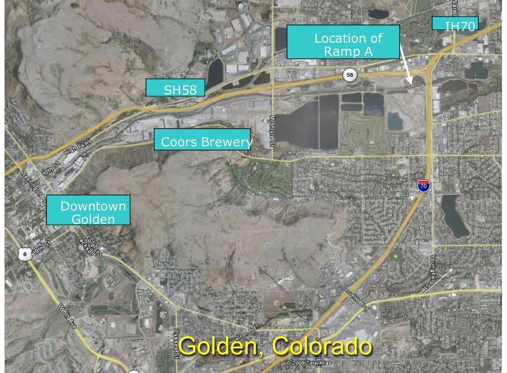
Golden, Colorado
IH70
SH58
DowntownGolden
Coors Brewery
Location ofRamp A
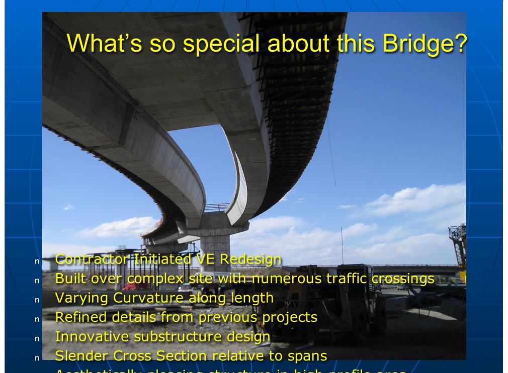
What’s so special about this Bridge?
n Contractor Initiated VE Redesignn Built over complex site with numerous traffic crossingsn Varying Curvature along lengthn Refined details from previous projectsn Innovative substructure designn Slender Cross Section relative to spansn Aesthetically pleasing structure in high profile area
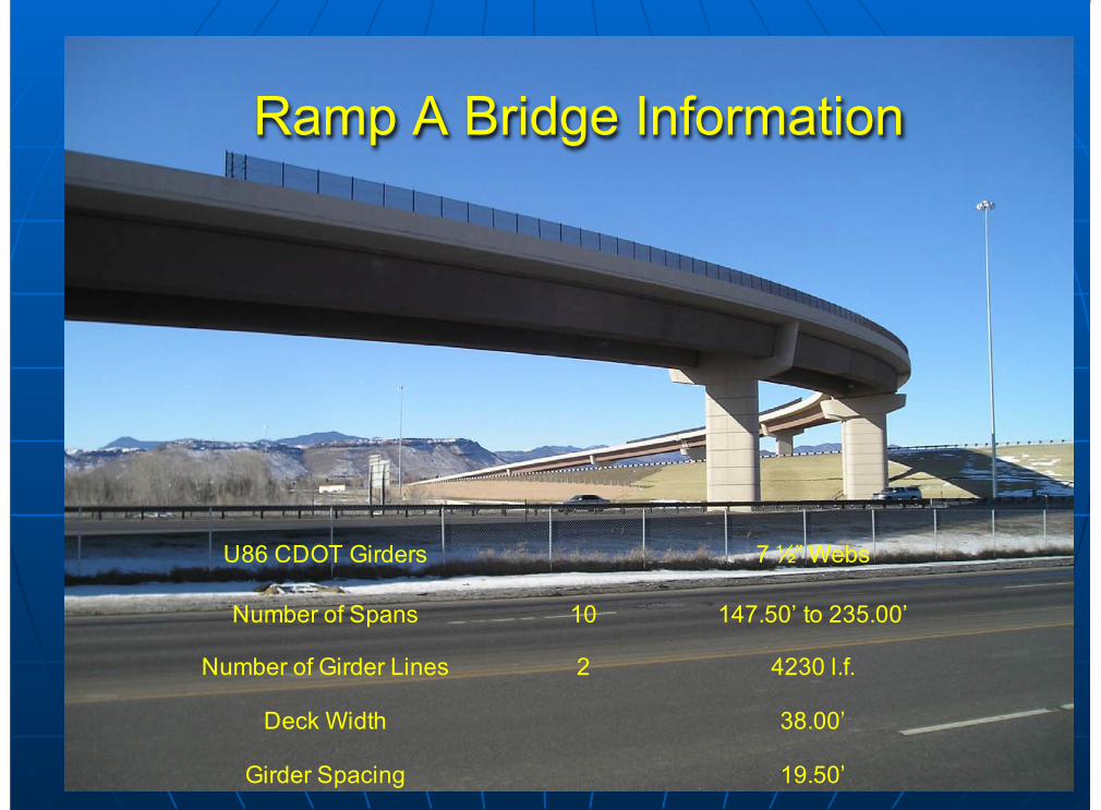
Ramp A Bridge Information
19.50’Girder Spacing
38.00’Deck Width
4230 l.f.2Number of Girder Lines
147.50’ to 235.00’10Number of Spans
7 ½” WebsU86 CDOT Girders
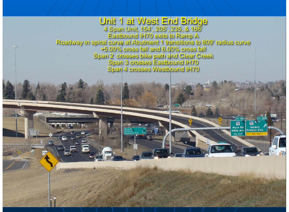
Unit 1 at West End Bridge4 Span Unit, 154’, 205’, 235, & 186’
Eastbound IH70 exits to Ramp ARoadway in spiral curve at Abutment 1 transitions to 809’ radius curve
+5.00% cross fall and 6.00% cross fallSpan 2 crosses bike path and Clear Creek
Span 3 crosses Eastbound IH70Span 4 crosses Westbound IH70
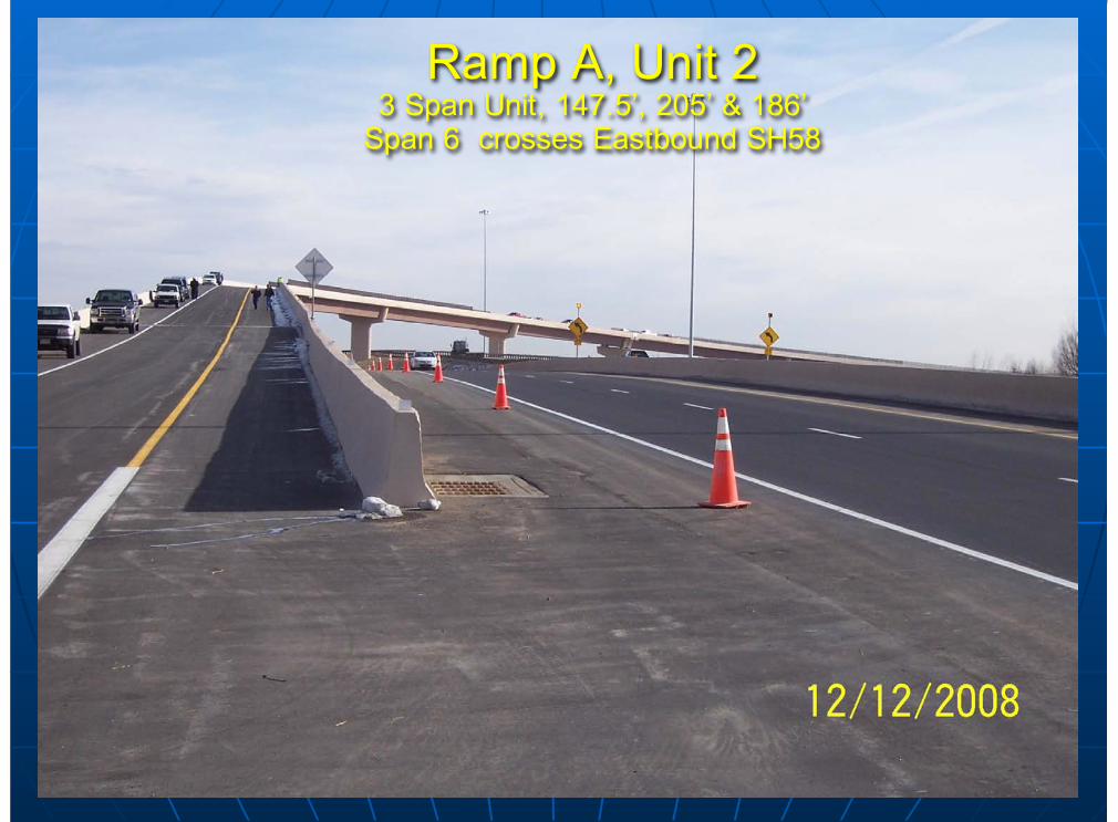
Ramp A, Unit 23 Span Unit, 147.5’, 205’ & 186’
Span 6 crosses Eastbound SH58
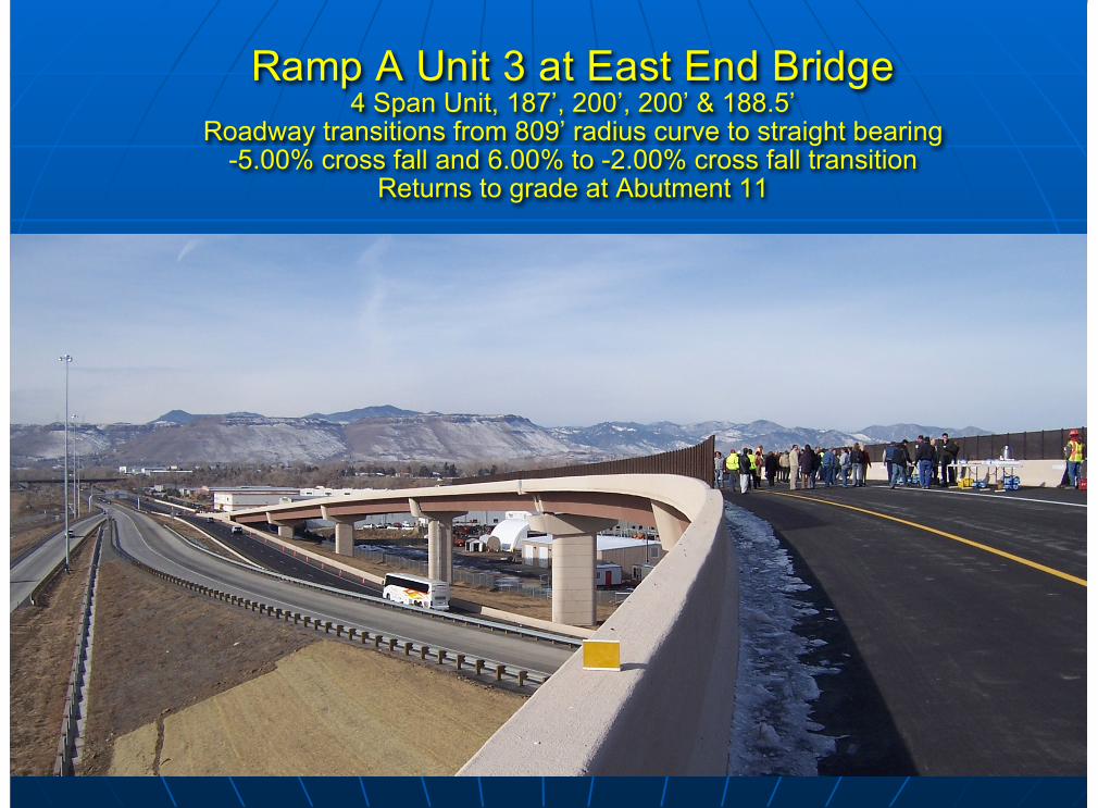
Ramp A Unit 3 at East End Bridge4 Span Unit, 187’, 200’, 200’ & 188.5’
Roadway transitions from 809’ radius curve to straight bearing-5.00% cross fall and 6.00% to -2.00% cross fall transition
Returns to grade at Abutment 11
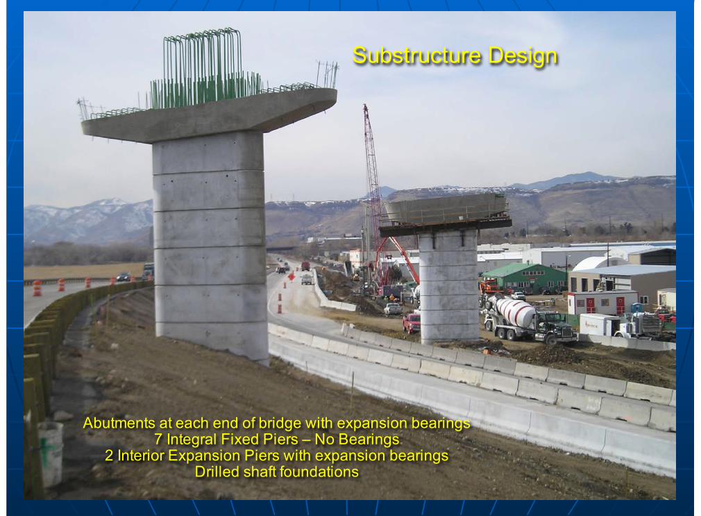
Abutments at each end of bridge with expansion bearings7 Integral Fixed Piers – No Bearings
2 Interior Expansion Piers with expansion bearingsDrilled shaft foundations
Substructure Design
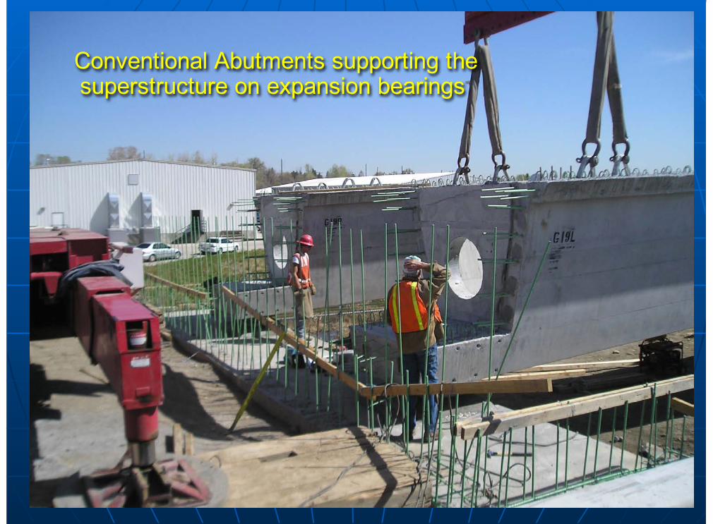
Conventional Abutments supporting thesuperstructure on expansion bearings
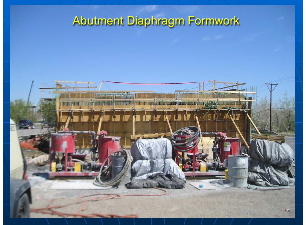
Abutment Diaphragm Formwork
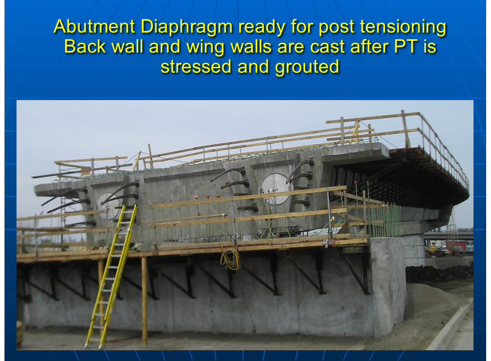
Abutment Diaphragm ready for post tensioningBack wall and wing walls are cast after PT is
stressed and grouted
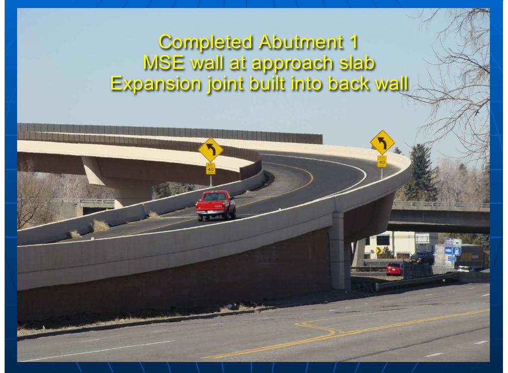
Completed Abutment 1MSE wall at approach slab
Expansion joint built into back wall
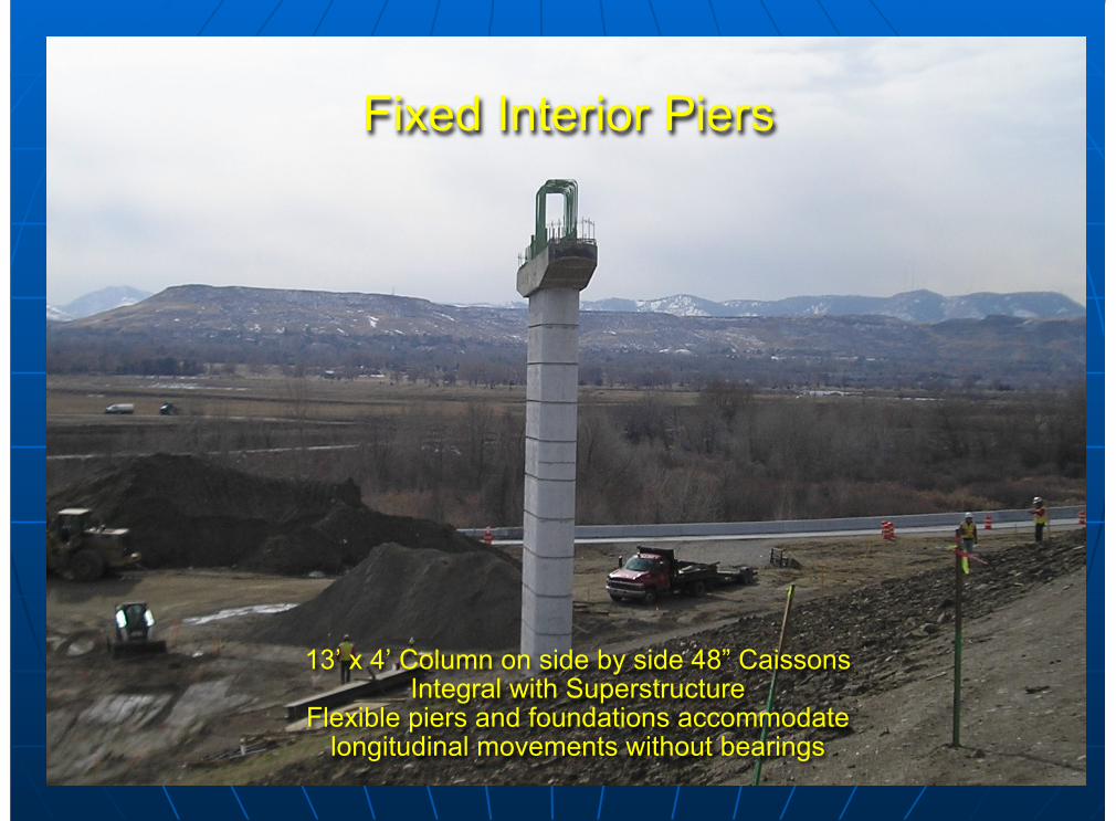
13’ x 4’ Column on side by side 48” CaissonsIntegral with Superstructure
Flexible piers and foundations accommodatelongitudinal movements without bearings
Fixed Interior Piers
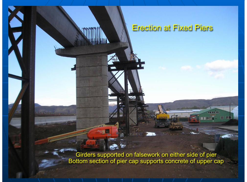
Girders supported on falsework on either side of pierBottom section of pier cap supports concrete of upper cap
Erection at Fixed Piers
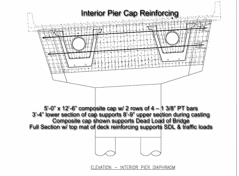
5’-0” x 12’-6” composite cap w/ 2 rows of 4 – 1 3/8” PT bars3’-4” lower section of cap supports 8’-9” upper section during casting
Composite cap shown supports Dead Load of BridgeFull Section w/ top mat of deck reinforcing supports SDL & traffic loads
Interior Pier Cap Reinforcing
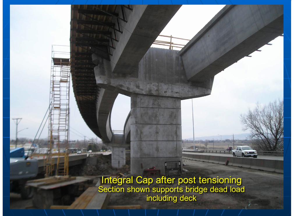
Integral Cap after post tensioningSection shown supports bridge dead load
including deck
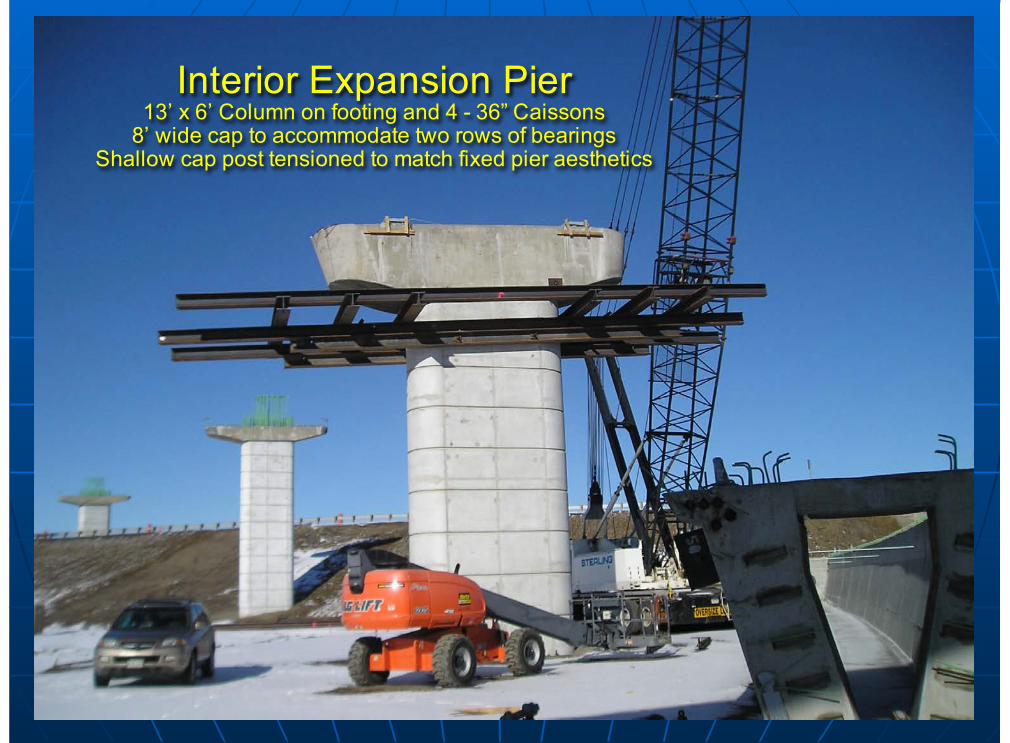
Interior Expansion Pier13’ x 6’ Column on footing and 4 - 36” Caissons
8’ wide cap to accommodate two rows of bearingsShallow cap post tensioned to match fixed pier aesthetics
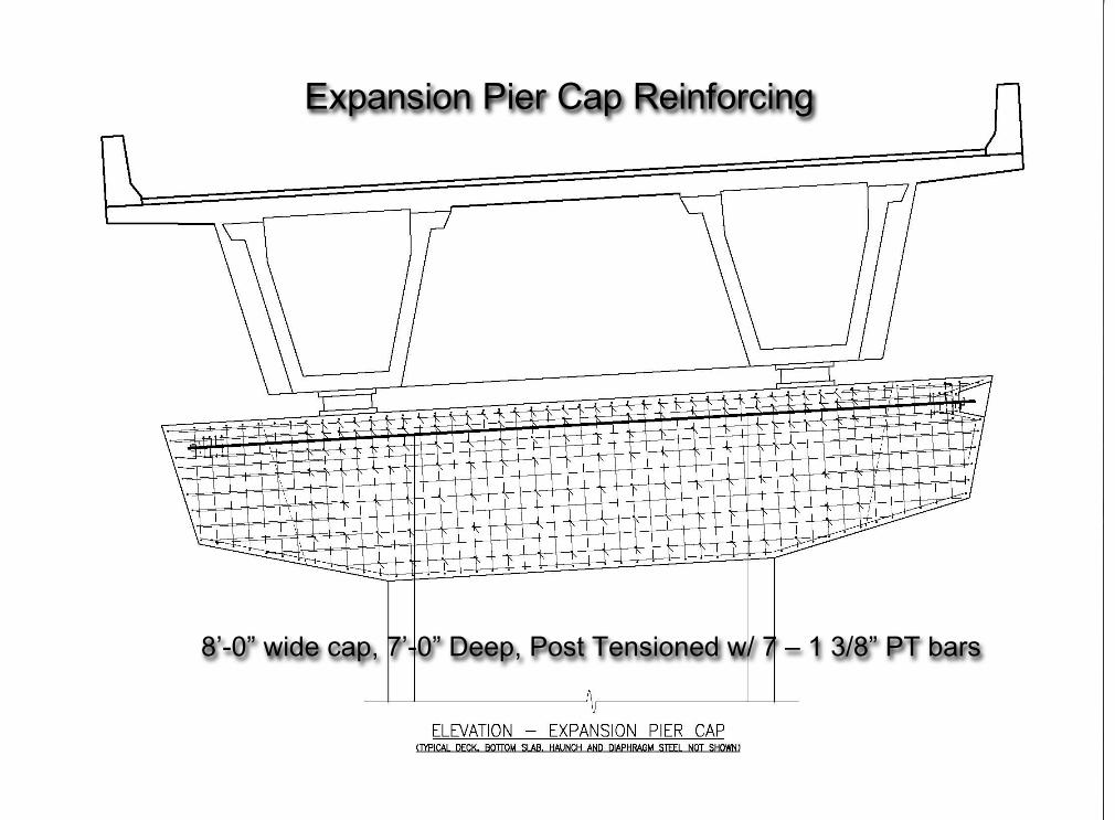
8’-0” wide cap, 7’-0” Deep, Post Tensioned w/ 7 – 1 3/8” PT bars
Expansion Pier Cap Reinforcing
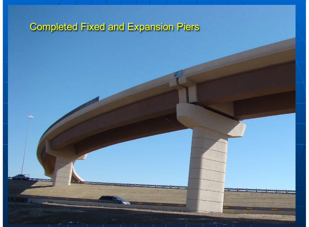
Completed Fixed and Expansion Piers
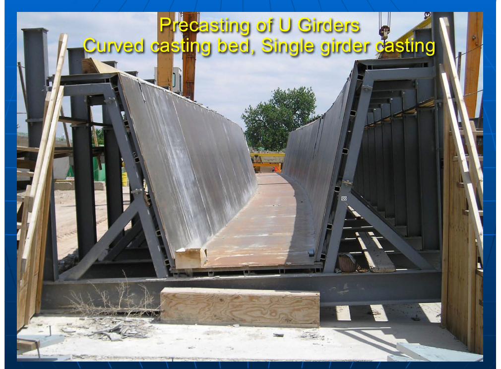
Precasting of U GirdersCurved casting bed, Single girder casting
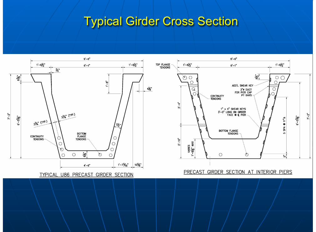
Typical Girder Cross Section
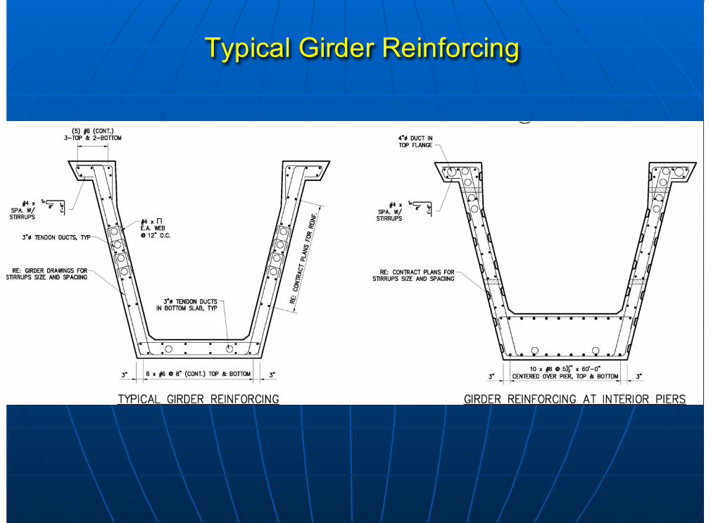
Typical Girder Reinforcing
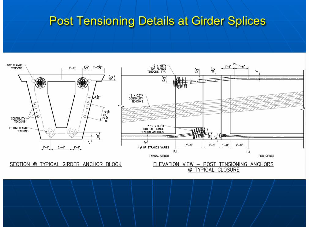
Post Tensioning Details at Girder Splices
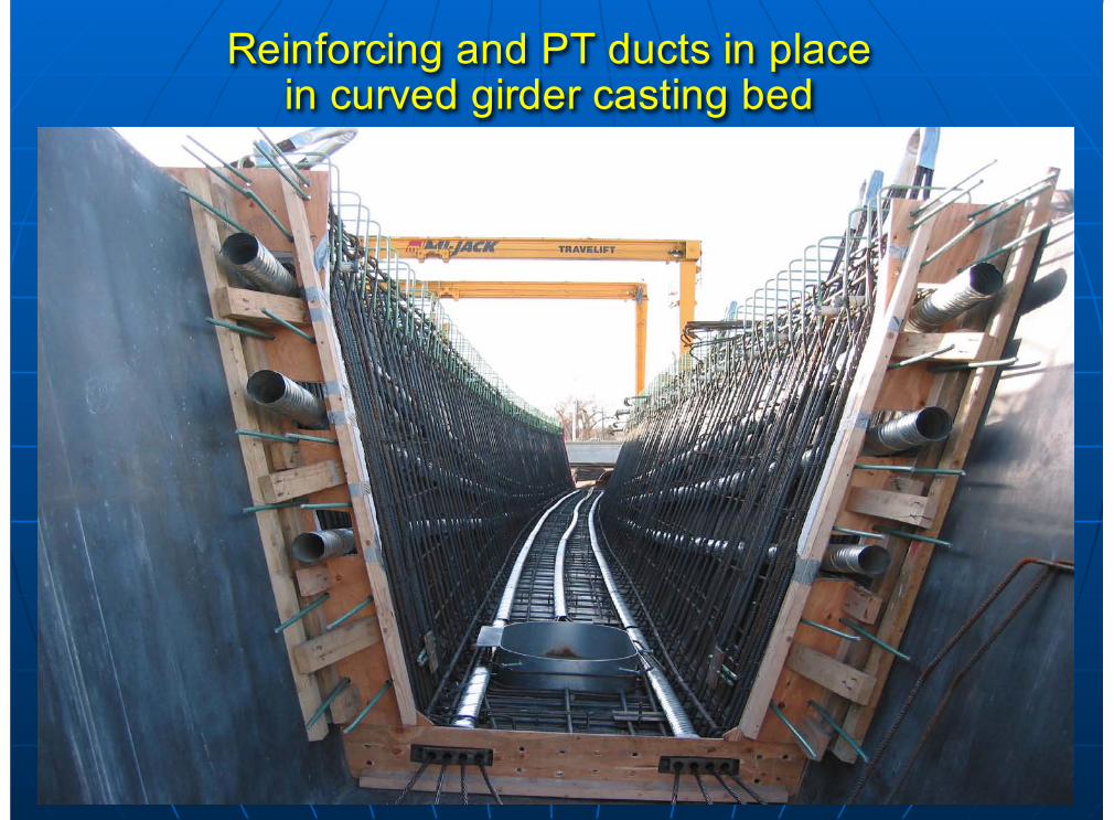
Reinforcing and PT ducts in placein curved girder casting bed
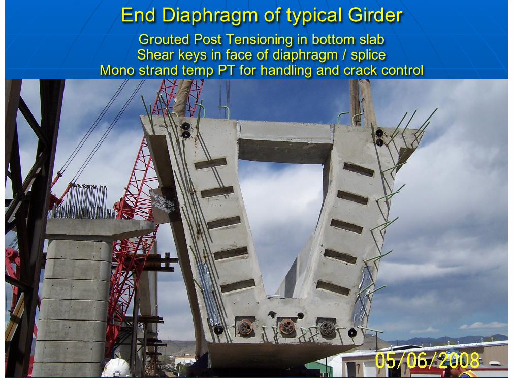
End Diaphragm of typical GirderGrouted Post Tensioning in bottom slabShear keys in face of diaphragm / splice
Mono strand temp PT for handling and crack control
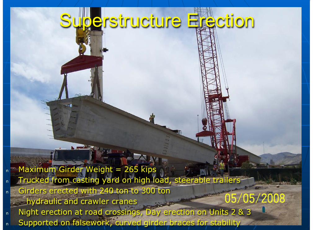
Superstructure Erection
n Maximum Girder Weight = 265 kipsn Trucked from casting yard on high load, steerable trailersn Girders erected with 240 ton to 300 ton hydraulic and crawler cranesn Night erection at road crossings, Day erection on Units 2 & 3n Supported on falsework, curved girder braces for stability
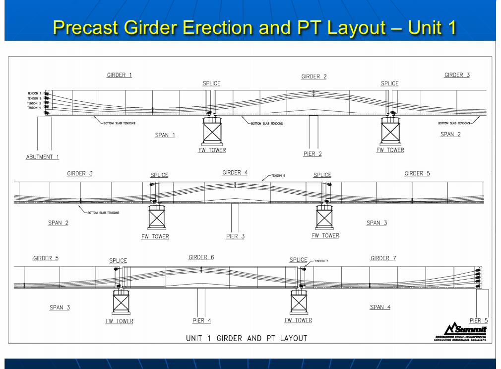
Precast Girder Erection and PT Layout – Unit 1
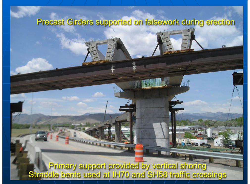
Primary support provided by vertical shoringStraddle bents used at IH70 and SH58 traffic crossings
Precast Girders supported on falsework during erection
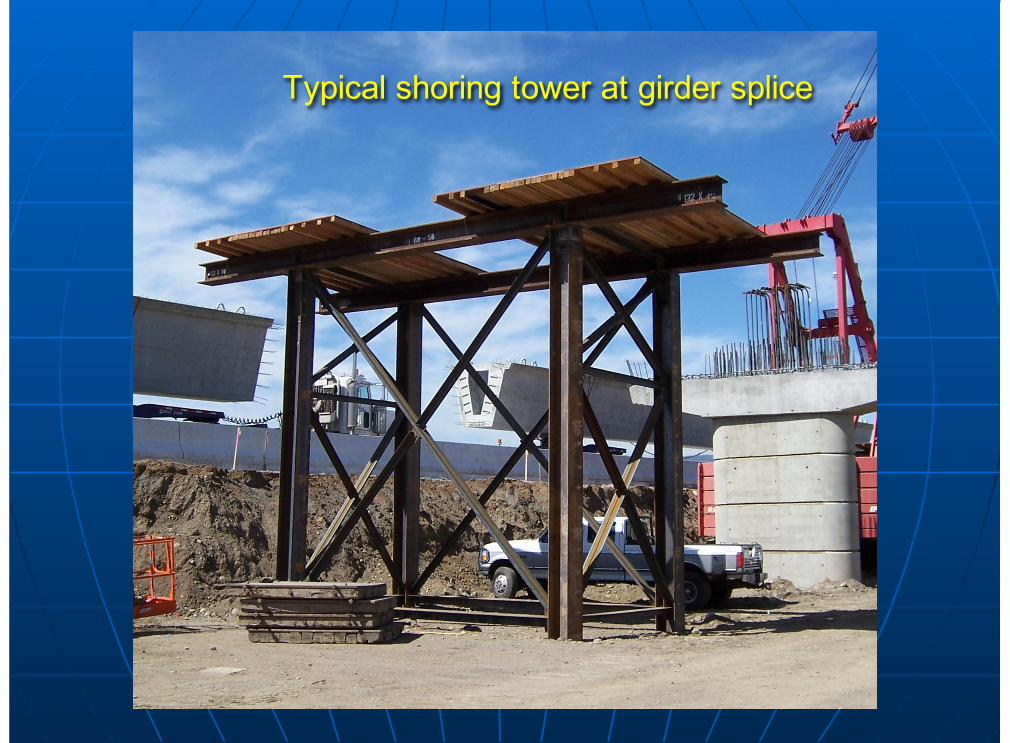
Typical shoring tower at girder splice
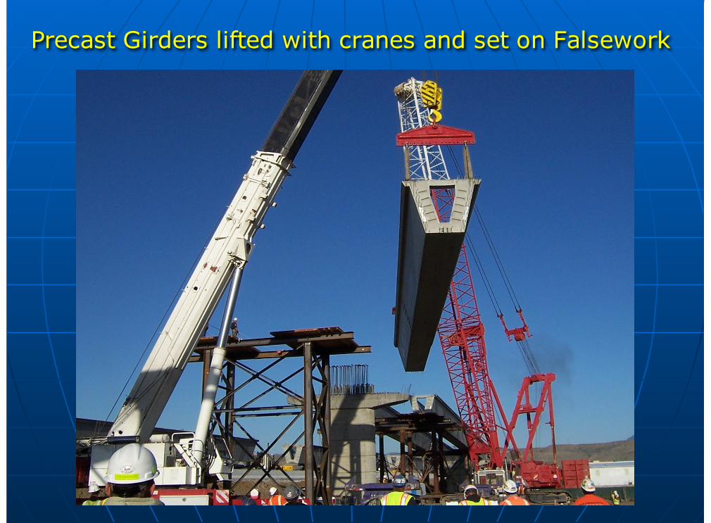
Precast Girders lifted with cranes and set on Falsework
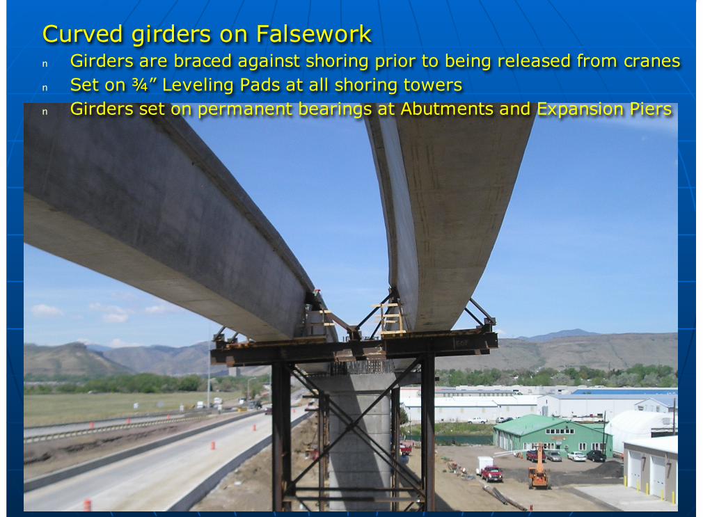
Curved girders on Falseworkn Girders are braced against shoring prior to being released from cranesn Set on ¾” Leveling Pads at all shoring towersn Girders set on permanent bearings at Abutments and Expansion Piers
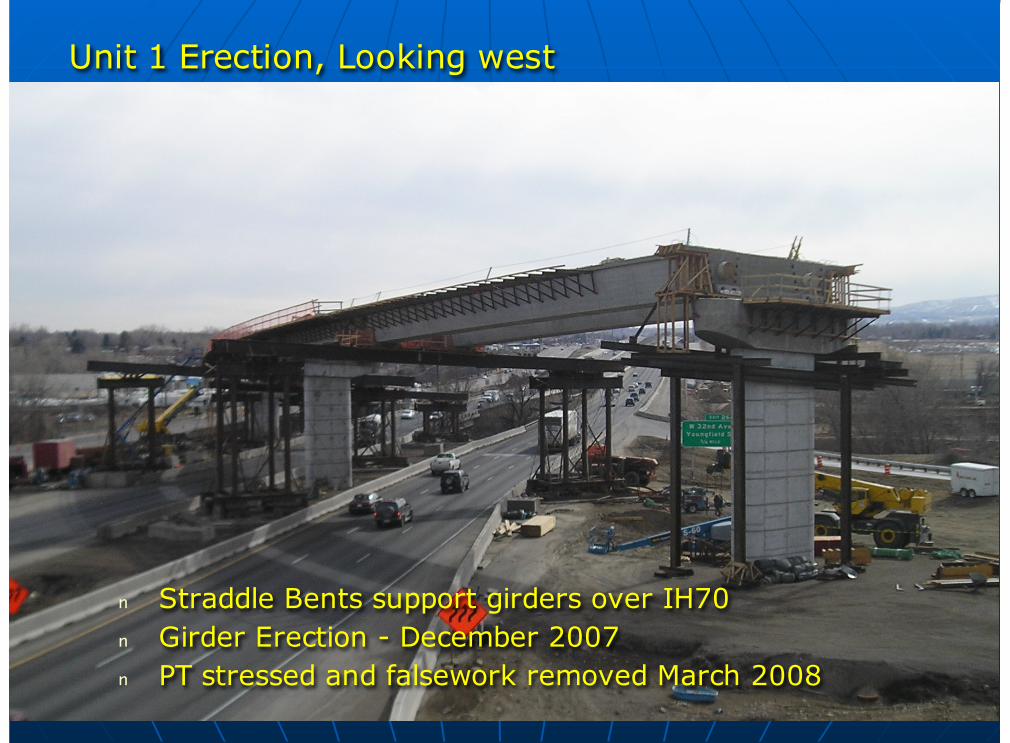
Unit 1 Erection, Looking west
n Straddle Bents support girders over IH70n Girder Erection - December 2007n PT stressed and falsework removed March 2008
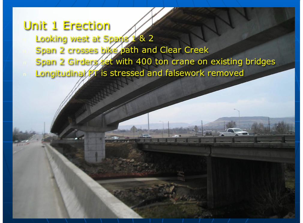
Unit 1 Erectionn Looking west at Spans 1 & 2n Span 2 crosses bike path and Clear Creekn Span 2 Girders set with 400 ton crane on existing bridgesn Longitudinal PT is stressed and falsework removed
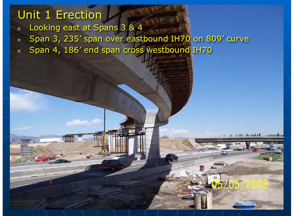
Unit 1 Erectionn Looking east at Spans 3 & 4n Span 3, 235’ span over eastbound IH70 on 809’ curven Span 4, 186’ end span cross westbound IH70
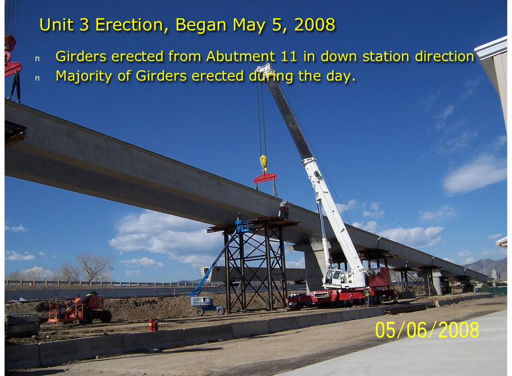
Unit 3 Erection, Began May 5, 2008
n Girders erected from Abutment 11 in down station directionn Majority of Girders erected during the day.
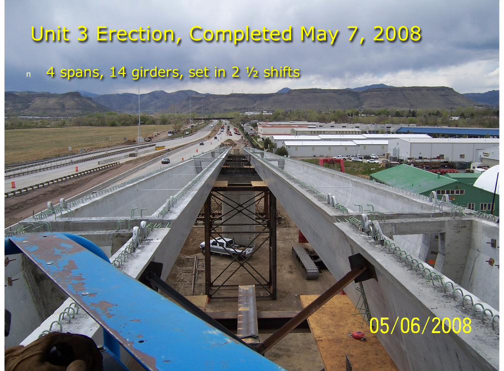
Unit 3 Erection, Completed May 7, 2008
n 4 spans, 14 girders, set in 2 ½ shifts
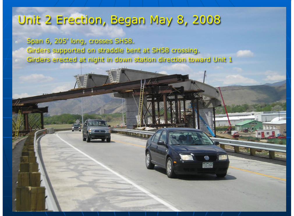
Unit 2 Erection, Began May 8, 2008
n Span 6, 205’ long, crosses SH58.n Girders supported on straddle bent at SH58 crossing.n Girders erected at night in down station direction toward Unit 1

Unit 2 Erection Completed, May 9, 2008Combined Units 2 & 3, 24 Girders set in 5 days
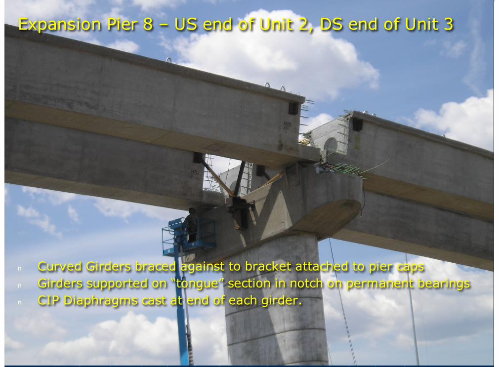
n Curved Girders braced against to bracket attached to pier capsn Girders supported on “tongue” section in notch on permanent bearingsn CIP Diaphragms cast at end of each girder.
Expansion Pier 8 – US end of Unit 2, DS end of Unit 3
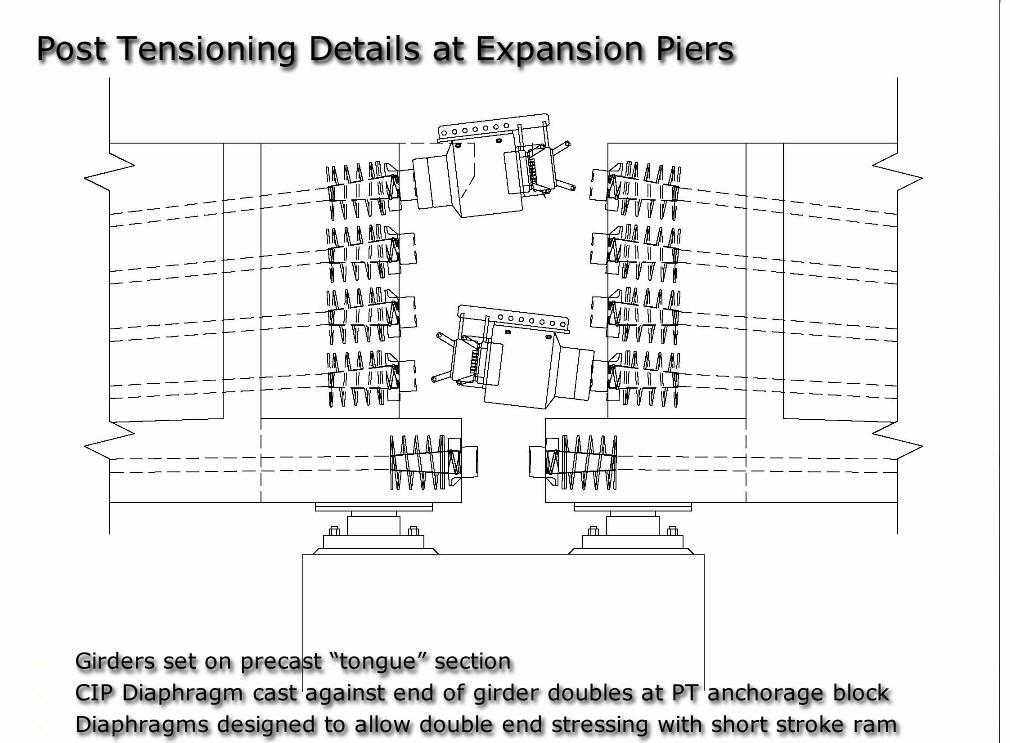
n Girders set on precast “tongue” sectionn CIP Diaphragm cast against end of girder doubles at PT anchorage blockn Diaphragms designed to allow double end stressing with short stroke ram
Post Tensioning Details at Expansion Piers
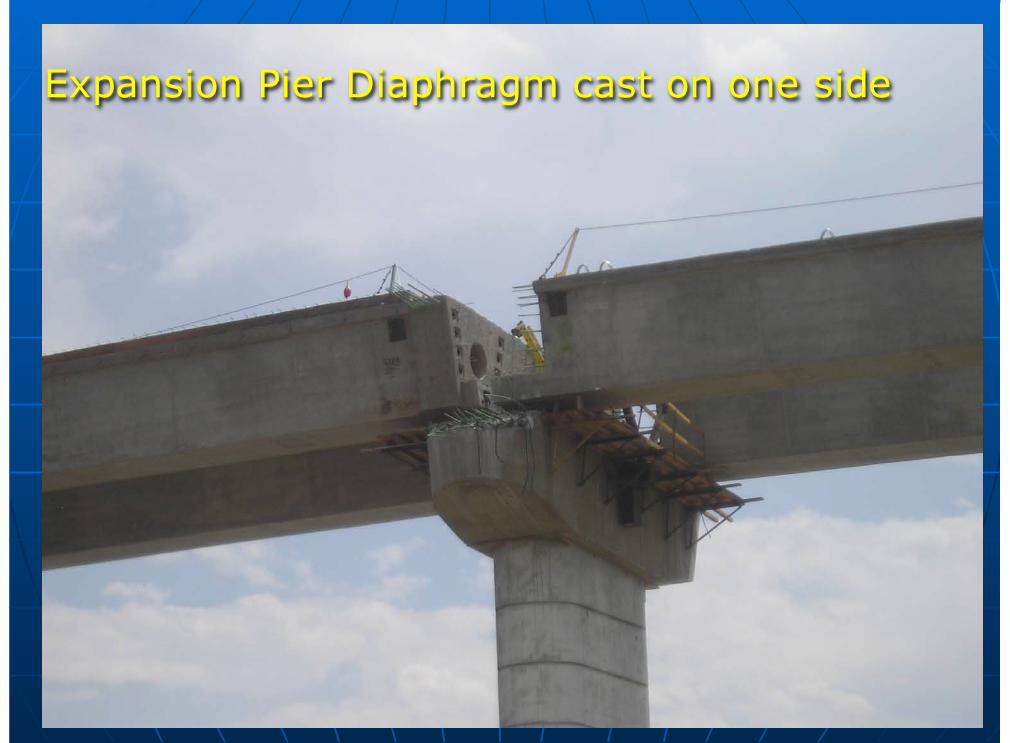
Expansion Pier Diaphragm cast on one side
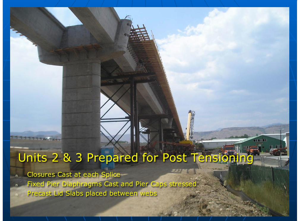
Units 2 & 3 Prepared for Post Tensioningn Closures Cast at each Splicen Fixed Pier Diaphragms Cast and Pier Caps stressedn Precast Lid Slabs placed between webs
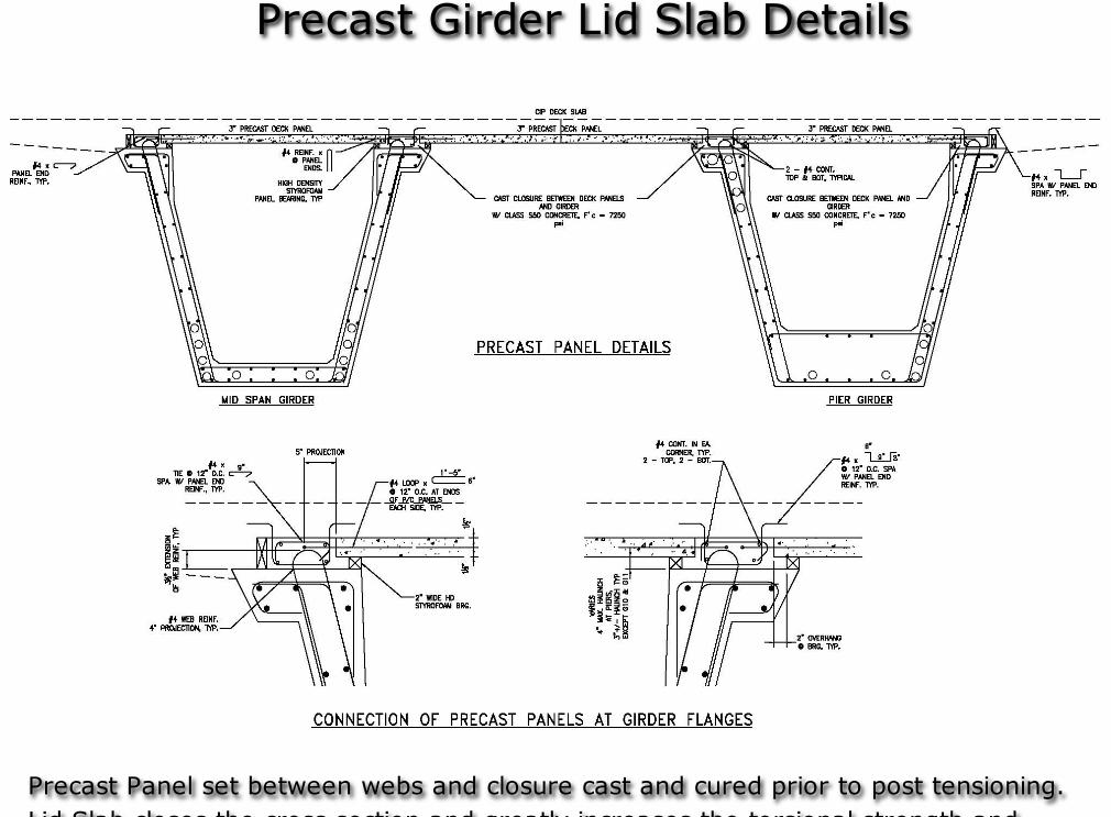
Precast Girder Lid Slab Details
Precast Panel set between webs and closure cast and cured prior to post tensioning.Lid Slab closes the cross section and greatly increases the torsional strength and
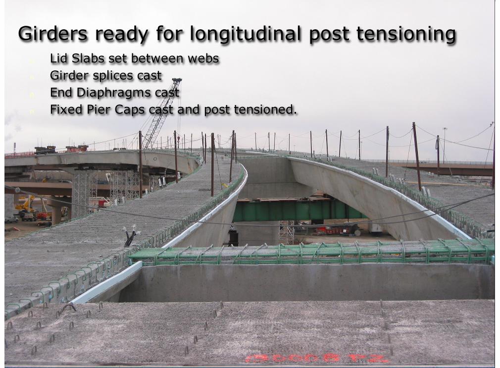
Girders ready for longitudinal post tensioningn Lid Slabs set between websn Girder splices castn End Diaphragms castn Fixed Pier Caps cast and post tensioned.
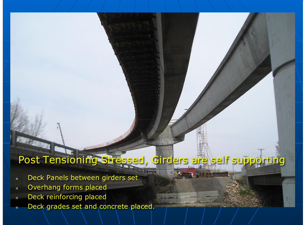
Post Tensioning Stressed, Girders are self supporting
n Deck Panels between girders setn Overhang forms placedn Deck reinforcing placedn Deck grades set and concrete placed.
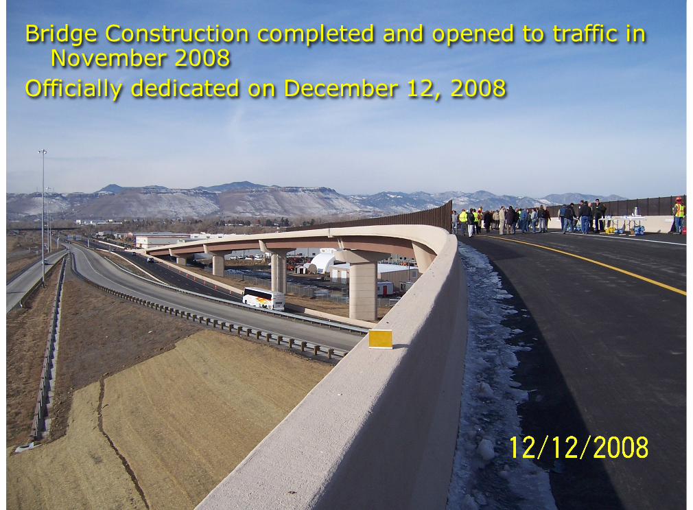
Bridge Construction completed and opened to traffic inNovember 2008
Officially dedicated on December 12, 2008
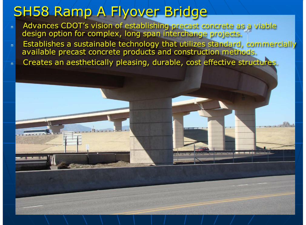
SH58 Ramp A Flyover Bridgen Advances CDOT’s vision of establishing precast concrete as a viable
design option for complex, long span interchange projects.n Establishes a sustainable technology that utilizes standard, commercially
available precast concrete products and construction methods.n Creates an aesthetically pleasing, durable, cost effective structures.