Embed Size (px)
Citation preview
109
The World Congress on Computer Science and Information Engineering 2011
Design and Development of System Integration for Fluoroscopic Navigation Using Surgical-Guiding Robot
Sakol Nakdhamabhorn1,2, Jackrit Suthakorn1,2,*, Member, IEEE, 1Department of Biomedical Engineering, 2Center for Biomedical and Robotic Technology,
Faculty of Engineering, Mahidol university, Sayala, Nakorn Pathom, Thailand *Corresponding Author: [email protected]
Abstract—Fluoroscopic x-ray is an essential tool for orthopedic surgery, especially, Close Intramedullary Nailing Operation. Close intramedullary nailing is a very efficiency technique for treatment the long bone fracture. In this technique, surgeon is required to insert an intramedullary nail into the medullary canal to stabilize the fractured bone. The most difficult task for the surgeon is to identify two screwing holes at the distal location of the nail. In conventional method, surgeon requires a lot of fluoroscopic exposures to recover distal interlocking holes. Therefore, both of surgeon and patient continually absorb an irradiation that is harmful for their long term health. This paper presents a system for fluoroscopic navigation in close intramedullary nailing. The systems are integrated with three sub-systems: 1) A recovery of distal interlocking holes system for locating distal interlocking holes. 2) An optical tracking system for registering an x-ray image coordinate into the world coordinate. 3) A surgical guiding robot system for guiding a position and orientation of distal interlocking holes using robot guidance.
Keywords-Intramedullary nailing; Fluoroscopic Navigation; Navigation System; Robot-Assisted Surgery; Computer-Intergrated Surgery;
I. INTRODUCTION Engineering and healthcare have been an important part of human life. Recently, engineering has paid more influence to several healthcare procedures. Computer-Integrated Surgery (CIS) and Robot-Assisted Surgery (RAS) play important roles in numerous medical operations. An important section of CIS/RAS is “medical navigation” which involves surgical planning and guiding in pre- and intra-operative procedures. Orthopedic surgery is one of the most common operations in hospitals. Closed intramedullary nailing (Closed Nailing) is a frequent orthopedic treatment for fixing a long bone’s fractures. This technique requires the surgeon to insert an intramedullary nail into the bone canal of the fractured long bone, such as, femur, tibia and humorous, after bone-fixing process. The intramedullary nail is used as an internal structure to hold the fractures together in their proper shapes. Closed Nailing is a minimally invasive surgery (MIS) which requires only a few small incisions during its process. That can prevent an infection at wound area and a bone can be healed by conventional healing process. Since surgeon inserted a nail into a bone completely. Surgeon proceeds to the
interlocking process. This process Surgeon needs to drill a bone and interlock by insert two screws into proximal and distal holes of intramedullary nail. At the proximal interlocking hole is easy to locate because a surgeon can use a mechanical mounted targeting device to aim that proximal hole. However, the most difficult task of this process is to locate position and orientation of distal interlocking holes. The two major causes of the difficulty of distal locking are: 1) C-arm image is two-dimensional image but the bone drilling trajectory needs to guide in three-dimensions. Therefore, a large number of C-arm images are required to target a bone drilling trajectory. That requires many time and x-ray radiation in the operation. 2) Intramedullary nail is deformed by external force and toques [1] during the insertion that changes a shape and position of distal holes in nail. Then an external mechanical guide cannot be used to target a drilling trajectory. In conventional method surgeon uses Fluoroscopic X-ray (C-arm) images to locate and identify the position and orientation of a distal locking hole of intramedullary nail. A surgeon uses trial and error to adjust C-arm into right position that is perpendicular with distal holes axis and makes distal holes appear perfectly circular shape on the screen. Therefore, a large number of X-ray images are required. The effect of X-ray radiation harms to both of surgeon and patient in long term health. The overall of radiation exposure time in close intramedullary nailing operation varies from 3 minute to 30 minute with 31%-51% of the overall radiation being from distal locking only depend on the patient anatomy and the surgeon’s skill [2].
Many devices and techniques [3] have been developed to overcome these difficulties. For example, nail mounted targeting device, image intensifier mounted targeting device, self locking nailing system, stereo fluoroscopy and computer navigation system. However, these devices and techniques have several disadvantages. For example, these devices are lack of versatility and user-interface. These are also not easy to use.
The concept of the proposed approach is to integrate systems including image processing system to locate position and orientation of distal interlocking holes, tracking and matching coordinate system and guidance system. The integrated system used for generating a navigation trajectory path of distal locking holes drilling axis.
110
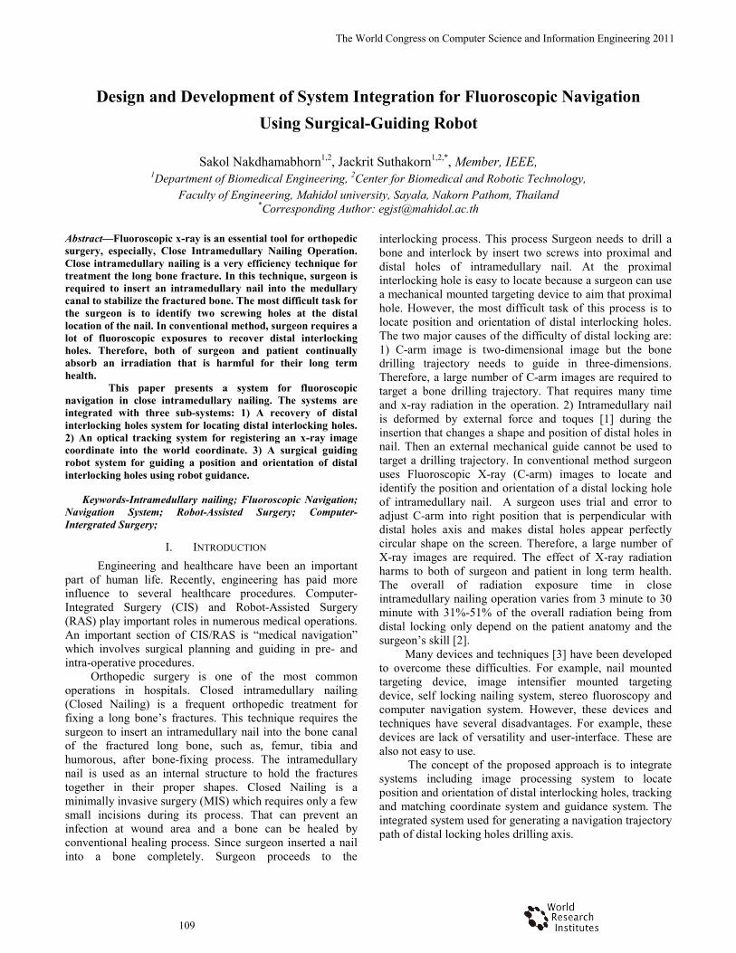
Figure 1. The series of Fluoroscopic X-ray tha
intramedullary nailing operation.
II. RELATED WORK Many Computer Integrated Surgery S
been proposed to assist operation espeinterlocking holes targeting. The main goaldifficulties in process, reduce time consusmall number of X-ray exposure. Thierry Ldeveloped a technique to recover a distal locused only two fluoroscopic images and nothe axis of hole. Both of two images are usecontour image of a nail and distal interlockincontour images acquired in different projethree dimensional model of nail and distal is constructed with the intersection of two of nail. That model can be visualized in pecomputer screen. In vivo experiments approximate 1.5 mm in translation and 1 deg
Guoyan Zheng et al, [7] developerecovery of distal interlocking hole. This wocalibrated and registered fluoroscopic imagthe recovery problem into a sequential two-optimal fitting process. The first stdetermination stage is used iteratively fittmodel to the image to estimate the axinterlocking holes. Then, next stage fotranslation and orientation of the distal inaround the estimated axis from first stage byfitting the geometrical models of the diholes. In vitro experiments were shown anerror of 0.48 degree and translational error o
Another approach proposed a system wto guide distal interlocking holes. Yaniv anddeveloped a precise robot assisted guidedistal locking intramedullary nail. This rmounted miniature robot fitted with a drill rigidly attached to the nail or bone. Therewas not serious about leg immobilizatioautomatic positioning a mechanical drill guon a robot using single fluoroscopic imageused 3-D Hough transform to locate the nmean accuracy in vitro experiment is angudegree and translation error of 3 mm.
at use in close
Systems [4] have ecially in distal l is to reduce the
uming and use a Leloup et al, [5-6] cking hole which
ot need to take at ed to determine a ng hole. The both ection plane. The interlocking hole projection cones
erspective on the the accuracy is
gree in rotation. ed an automatic ork based on two
ges. They defined stage model-base tage nail axis ing a cylindrical
xis of the distal or resolving the nterlocking holes y using iteratively istal interlocking
n average angular of 0.09 mm. which used robot d Joskowicz [8-9] e positioning for robot is a bone-guide. The robot
efore, the system on. The system
uide that mounted e. The system is
nail contour. The ular error of 1.3
III. DESIGN AND DE
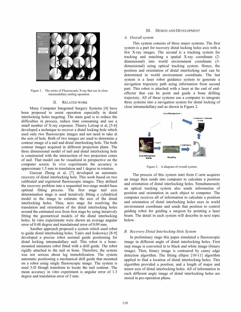
A. Overall system This system consists of three
system is a part for recovery distal few X-ray images. The second istracking and matching a spatialdimensional) into world envirodimensional) using optical trackiposition and orientation of distal determined in world environmensystem is a laser robot guidancenavigation trajectory path using inpart. This robot is attached with a effecter that can be point and trajectory. All of these systems usethree systems into a navigation sysclose intramedullary nail as shown i
Figure 2. A diagram of ov
The process of this system stan image then sends into computeand orientation of distal interlockinan optical tracking system alsoposition and orientation in each ocomputer receives all of informatioand orientation of distal interlockienvironment coordinate and sends guiding robot for guiding a surgebeam. The detail in each system wbelow.
B. Recovery Distal Interlocking HoIn preliminary stage this paper
image in different angle of distal step image is converted in to black image). Then, binary image is codetection algorithm. The fitting eapplied to find a location of distal algorithm provided a position, andminor axis of distal interlocking hoeach different angle image of distastored in pre-operation phase.
EVELOPMENT
major systems. The first locking holes axis with a s a tracking system for l X-ray coordinate (2-onment coordinate (3-ing system. Hence, the interlocking nail can be
nt coordinate. The last e system to generate a nformation from second laser at the end of end-guide a bone drilling
e a computer to integrate stem for distal locking of in Figure 2.
verall system.
tart from C-arm acquires er to calculate a position ng holes. Simultaneously o sends information of object to computer. The on to calculate a position ing holes axes in world that position to control
eon by pointing a laser will describe in next topic
ole System simulated a fluoroscopic interlocking holes. First and white image (binary
ontoured by canny edge llipse [10-11] algorithm interlocking holes. This
d a length of major and les. All of information in al interlocking holes are
111
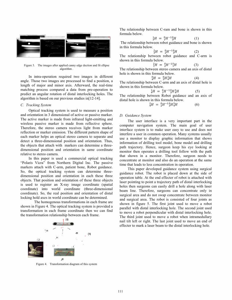
Figure 3. The images after applied canny edge dec
algorithm .
In intra-operation required two imaangle. Those two images are processed to flength of major and minor axis. Afterwarmatching process compared a data from predict an angular rotation of distal interloalgorithm is based on our previous studies in
C. Tracking System Optical tracking system is used to me
and orientation in 3 dimensional of active orThe active marker is made from infrared liwireless passive marker is made from rTherefore, the stereo camera receives ligreflection or marker emission. The differenteach marker helps an optical stereo cameradetect a three-dimensional position and othe objects that attach with markers can dedimensional position and orientation in relative to stereo camera.
In this paper is used a commercial “Polaris Vicra” from Northern Digital Inmarkers attach with C-arm, patient bone, So, the optical tracking system can ddimensional position and orientation in eobjects. That position and orientation of this used to register an X-ray image coocoordinate) into world coordinate (thcoordinate). So, the real position and orielocking hold axes in world coordinate can b
The homogenous transformations ishown in Figure 4. The optical tracking systtransformation in each frame coordinate ththe transformation relationship between eac
Figure 4. Transformation diagram of thi
ction and fit ellipse
ages in different find a position, a rd, the real-time pre-operation to cking holes. The n[12-14].
easure a position r passive marker. ight-emitting and eflective sphere.
ght from marker t pattern shape of a to separate and
orientation. Thus, etermine a three-same coordinate
optical tracking nc. The passive Robot guidance.
determine three-each these three
hese three objects ordinate (spatial hree-dimensional entation of distal be determined. in each frame are tem is provided a hen we can find h frame.
s system
The relationship between C-ram anformula below.
The relationship between robot guiin this formula below.
The relationship between robot gshown in this formula below.
The relationship between stereo camhole is shown in this formula below
The relationship between C-arm andshown in this formula below.
The relationship between Robot gdistal hole is shown in this formula
D. Guidance System The user interface is a very
computer navigation system. Thinterface system is to make user einterfere a user in common operatiouse a monitor to display graphic information of drilling tool model, path trajectory. Hence, surgeon kmonitor then operates a drilling tothat shown in a monitor. Thereconcentrate at monitor and also do time that leads to less concentration
This paper developed guidancguidance robot. The robot is placoperation table. At the end effecter laser pointing to point a trajectory pholes then surgeons can easily drilbeam line. Therefore, surgeons csurgical area and do not swap concand surgical area. The robot is coshown in figure 5. The first jointparallel with distal interlocking holto move a robot perpendicular withThe third joint used to move a robnail tilt left or right. The last joint effecter to mark a laser beam to the
nd bone is shown in this
(1) dance and bone is shown
(2) guidance and C-arm is
(3) mera and an axis of distal
w. (4) d an axis of distal hole is
(5) guidance and an axis of below.
(6)
y important part in the he main goal of user easy to use and does not on. Many systems usually
information that shows bone model and drilling
keep his eye looking at ool follow with the path efore, surgeon needs to
an operation at the same n in operation. ce system using surgical ced down at the side of
of robot is attached with path of distal interlocking l a hole along with laser can concentrate only in centrate between monitor onsisted of four joints as t used to move a robot le. The second joint used h distal interlocking hole. bot when intramedullary used to move an end of distal interlocking hole.
112
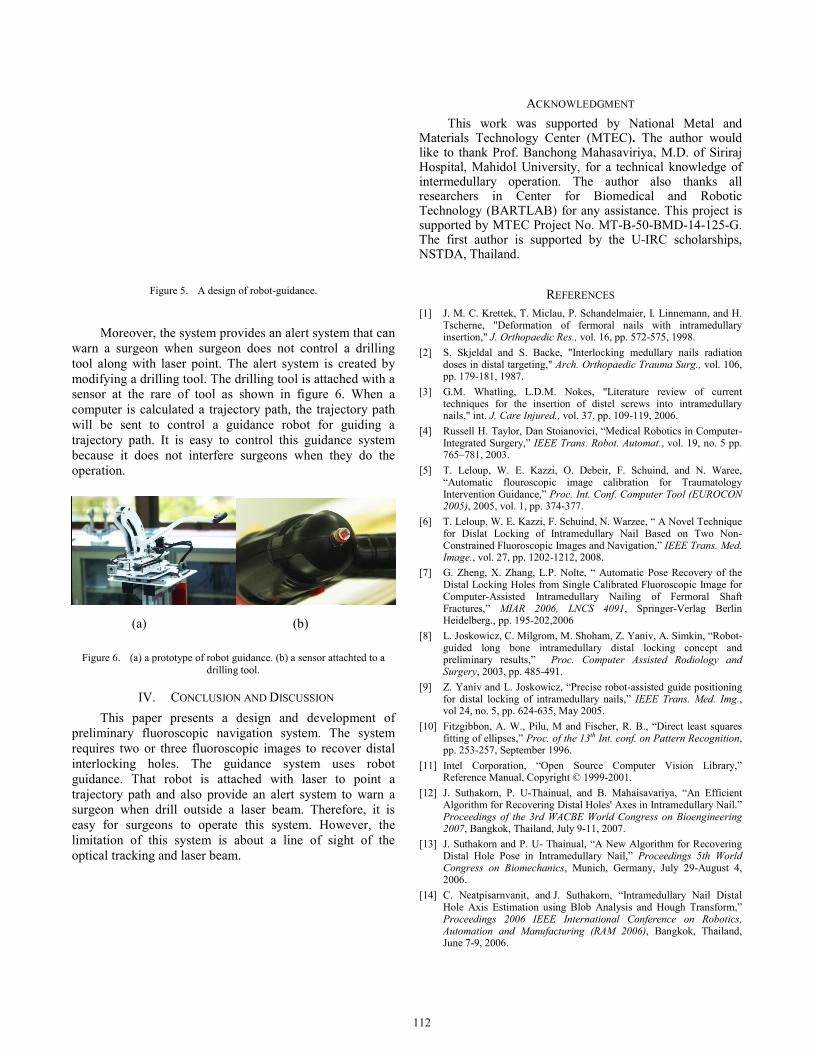
Figure 5. A design of robot-guidan
Moreover, the system provides an aler
warn a surgeon when surgeon does not ctool along with laser point. The alert systemodifying a drilling tool. The drilling tool isensor at the rare of tool as shown in ficomputer is calculated a trajectory path, thwill be sent to control a guidance robotrajectory path. It is easy to control this because it does not interfere surgeons whoperation.
(a) (b)
Figure 6. (a) a prototype of robot guidance. (b) a sedrilling tool.
IV. CONCLUSION AND DISCUS
This paper presents a design and preliminary fluoroscopic navigation systerequires two or three fluoroscopic images interlocking holes. The guidance systguidance. That robot is attached with ltrajectory path and also provide an alert ssurgeon when drill outside a laser beam. easy for surgeons to operate this systemlimitation of this system is about a line optical tracking and laser beam.
nce.
rt system that can control a drilling em is created by is attached with a igure 6. When a he trajectory path ot for guiding a guidance system hen they do the
)
ensor attachted to a
SSION development of
em. The system to recover distal em uses robot laser to point a system to warn a
Therefore, it is m. However, the
of sight of the
ACKNOWLEDGM
This work was supported bMaterials Technology Center (MTlike to thank Prof. Banchong MahaHospital, Mahidol University, for aintermedullary operation. The aresearchers in Center for BioTechnology (BARTLAB) for any asupported by MTEC Project No. MThe first author is supported by NSTDA, Thailand.
REFERENCE
[1] J. M. C. Krettek, T. Miclau, P. SchandTscherne, "Deformation of fermorainsertion," J. Orthopaedic Res., vol. 16
[2] S. Skjeldal and S. Backe, "Interlockdoses in distal targeting," Arch. Orthoppp. 179-181, 1987.
[3] G.M. Whatling, L.D.M. Nokes, "Ltechniques for the insertion of distenails," int. J. Care Injured., vol. 37, pp
[4] Russell H. Taylor, Dan Stoianovici, “MIntegrated Surgery,” IEEE Trans. Rob765–781, 2003.
[5] T. Leloup, W. E. Kazzi, O. Debeir“Automatic flouroscopic image caIntervention Guidance,” Proc. Int. Con2005), 2005, vol. 1, pp. 374-377.
[6] T. Leloup, W. E. Kazzi, F. Schuind, N.for Dislat Locking of IntramedullarConstrained Fluoroscopic Images and NImage., vol. 27, pp. 1202-1212, 2008.
[7] G. Zheng, X. Zhang, L.P. Nolte, “ AuDistal Locking Holes from Single CaliComputer-Assisted Intramedullary Fractures,” MIAR 2006, LNCS 4Heidelberg., pp. 195-202,2006
[8] L. Joskowicz, C. Milgrom, M. Shohamguided long bone intramedullary preliminary results,” Proc. CompuSurgery, 2003, pp. 485-491.
[9] Z. Yaniv and L. Joskowicz, “Precise rfor distal locking of intramedullary nvol 24, no. 5, pp. 624-635, May 2005.
[10] Fitzgibbon, A. W., Pilu, M and Fischefitting of ellipses,” Proc. of the 13th Intpp. 253-257, September 1996.
[11] Intel Corporation, “Open Source Reference Manual, Copyright © 1999-2
[12] J. Suthakorn, P. U-Thainual, and B. Algorithm for Recovering Distal HolesProceedings of the 3rd WACBE Worl2007, Bangkok, Thailand, July 9-11, 20
[13] J. Suthakorn and P. U- Thainual, “A NDistal Hole Pose in Intramedullary NCongress on Biomechanics, Munich, 2006.
[14] C. Neatpisarnvanit, and J. SuthakornHole Axis Estimation using Blob AnProceedings 2006 IEEE InternationAutomation and Manufacturing (RAMJune 7-9, 2006.
MENT by National Metal and
TEC). The author would asaviriya, M.D. of Siriraj a technical knowledge of author also thanks all omedical and Robotic assistance. This project is
MT-B-50-BMD-14-125-G. the U-IRC scholarships,
ES delmaier, I. Linnemann, and H. al nails with intramedullary
6, pp. 572-575, 1998. king medullary nails radiation paedic Trauma Surg., vol. 106,
Literature review of current el screws into intramedullary . 109-119, 2006.
Medical Robotics in Computer-ot. Automat., vol. 19, no. 5 pp.
, F. Schuind, and N. Waree, alibration for Traumatology nf. Computer Tool (EUROCON
. Warzee, “ A Novel Technique ry Nail Based on Two Non-Navigation,” IEEE Trans. Med.
utomatic Pose Recovery of the ibrated Fluoroscopic Image for Nailing of Fermoral Shaft 091, Springer-Verlag Berlin
m, Z. Yaniv, A. Simkin, “Robot-distal locking concept and
uter Assisted Rodiology and
obot-assisted guide positioning nails,” IEEE Trans. Med. Img.,
er, R. B., “Direct least squares t. conf. on Pattern Recognition,
Computer Vision Library,” 2001. Mahaisavariya, “An Efficient
s' Axes in Intramedullary Nail.” ld Congress on Bioengineering 007. New Algorithm for Recovering Nail,” Proceedings 5th World
Germany, July 29-August 4,
n, “Intramedullary Nail Distal alysis and Hough Transform,” nal Conference on Robotics, M 2006), Bangkok, Thailand,