Embed Size (px)
Citation preview
www.ijcrt.org © 2020 IJCRT | Volume 8, Issue 9 September 2020 | ISSN: 2320-2882
IJCRT2009081 International Journal of Creative Research Thoughts (IJCRT) www.ijcrt.org 608
Design and Evaluation of Arc welded MS & SS plates
to find the effect of bend radius at different load
conditions
1P. Varalakshmi, 2Guda Revanth Kumar, 3Datrika Sri Harshitha, 4Aska Mukhul Vamshi, 5Chetty akhila 1Assitant Professor, 2345Student,
12345Mechanical Department, 12345Guru Nanak Institute of Technology, Hyderabad, Telangana, India.
Abstract— Arc welding is a process of joining metals by using electrodes, by using high heat to melt the parts together and allow them to cool causing fusion. It is a
type of welding to join metals, other than joining process like brazing and soldering. We have used two different metals like Mild steel (MS) and Stainless steel
(SS) plates with different thickness about 8mm and 10mm. We have done Arc welding on MS and SS plates with different thickness. By using electrode
E7018 with different gauges like 2mm, 3.5mm, 4mm for (filling V-GROVE) applying 3 layers of weld bead, for finding the welding defects on weld joint. The following tests conducted are hardness, dye-penetration, Magnetic and radiography. We mainly concentrated on finding the effect of bending radius on weld
joint. By applying the different loading conditions bend radius and angle of inclination are obtained. With the help of CAD (computer aided design)
application with CREO parametric, we have designed the welded plates and performed analysis using ANSYS software. By using this software, the theoretical
and experimental values are evaluated.
Keywords: Arc welding, MS and SS plates, electrode, CAD, CREO, ANSYS.
I. INTRODUCTION
CREO Parametric is a modern computer aided design (CAD) program. It enables designers to create a mathematically correct solid model of an object that
can be stored in a database. When the mathematical model of a part or assembly is associated with the properties of the materials used, we get a solid model
that can be used to simulate and predict the behavior of the part or model with finite element and other simulation software. The same solid model can be
used to manufacture the object and also contains the information necessary to inspect and assemble the product. The marketing organization can produce sales brochures and videos that introduce the product to potential customers. CREO Parametric and similar CAD programs have made possible concurrent
engineering, where all the groups that contribute to the product development process can share information real-time.
ANSYS is engineering simulation software that predicts with confidence about the performance of the product under the real-world environments
incorporating all the existing physical phenomena. While performing the part of composite analysis, the composite properties were imposed only in the full-length leaves by incorporating the new value of elastic modulus obtained from the rule of mixtures. The layout of static analysis involves meshing, boundary
conditions and loading.
Welding is a process of joining two similar and Non-similar metal or non-metal with the application of heat and pressure, but in some cases without the application of pressure the process has been done. The electrode is used to join the metal in Arc welding process with the help of spool gun. Welding is used
for making permanent joints[7]. It is used for the manufacturing of automobile parts, railway wagons, aircraft frames, machine parts, tanks, structural works,
boilers, ship building furniture etc. Arc welding is a process which produces the coalescence of metals by heating them with an arc between a continuously
fed filler metal electrode and the work[1]. These are the parameters that are used for the Arc welding process. By this we can do the arc welding with the represented size of the electrode and the type
of the electrode that used[2].
www.ijcrt.org © 2020 IJCRT | Volume 8, Issue 9 September 2020 | ISSN: 2320-2882
IJCRT2009081 International Journal of Creative Research Thoughts (IJCRT) www.ijcrt.org 609
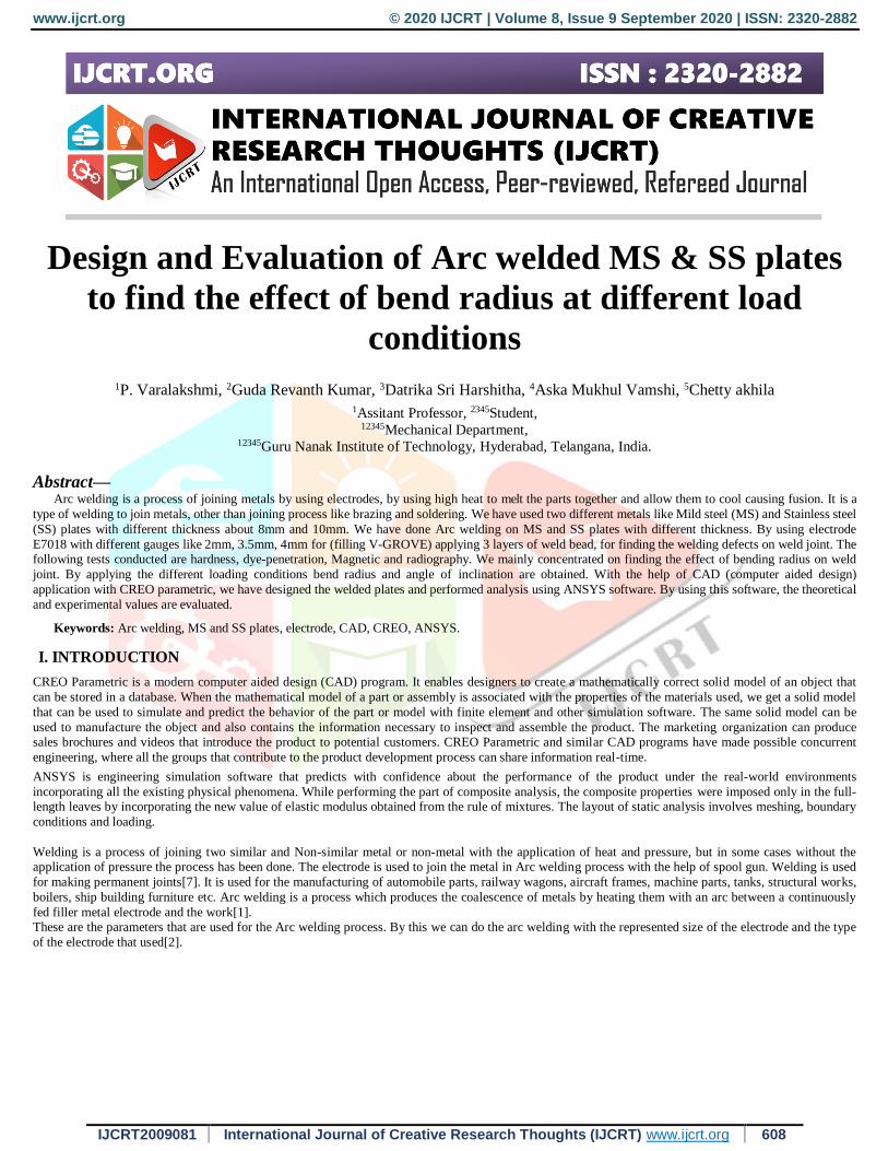
Figure- Arc welding process
For finding the bend radius, The bend allowance (BA)[8] is the length of the arc of the neutral line between the tangent points of a bend in any material.
Adding the length of each flange taken between the center of the radius to the BA gives the Flat Pattern length. This bend al lowance formula is used to
determine the flat pattern length when a bend is dimensioned from 1) the center of the radius, 2) a tangent point of the radius or 3) the outside tangent point of the radius on an acute angle bend. There is a procedure to find the end radius
1. Design of weld joints
2. Testing the joints both practical and analytical
3. Comparing the both analytical and practical values
II.DESIGN OF WELD JOINTS:
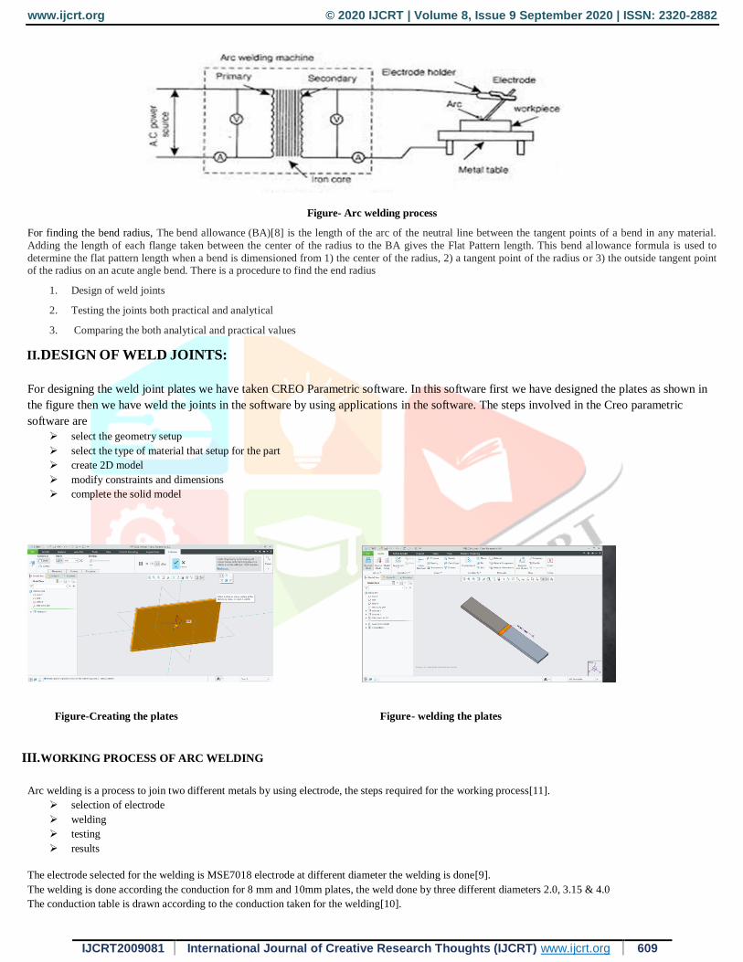
For designing the weld joint plates we have taken CREO Parametric software. In this software first we have designed the plates as shown in
the figure then we have weld the joints in the software by using applications in the software. The steps involved in the Creo parametric
software are
select the geometry setup
select the type of material that setup for the part
create 2D model
modify constraints and dimensions
complete the solid model
Figure-Creating the plates Figure- welding the plates
III.WORKING PROCESS OF ARC WELDING
Arc welding is a process to join two different metals by using electrode, the steps required for the working process[11].
selection of electrode
welding
testing
results
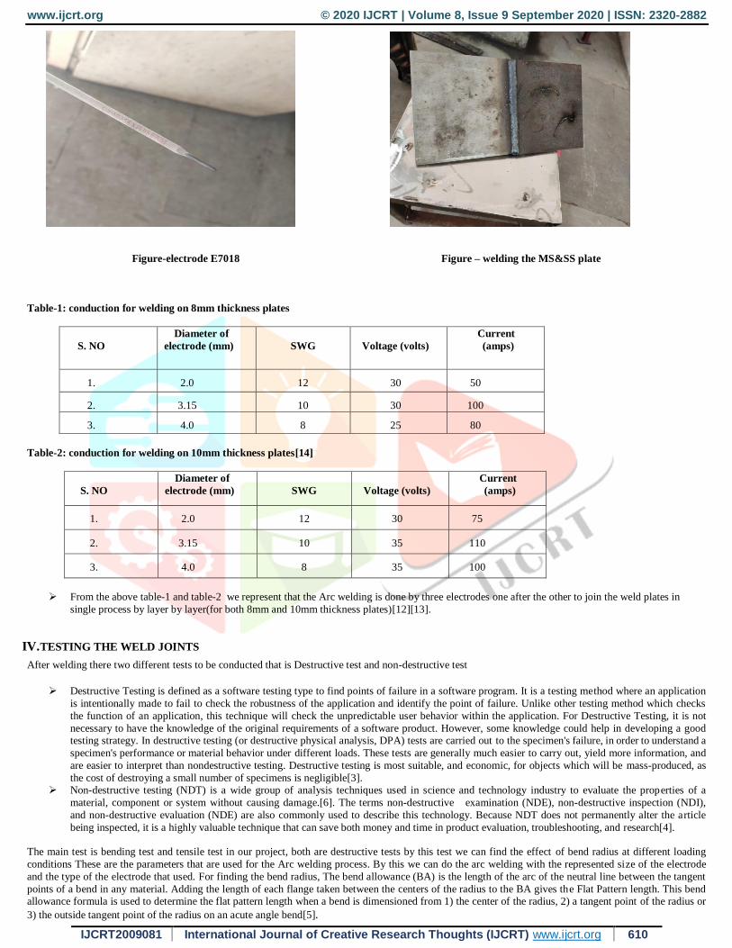
The electrode selected for the welding is MSE7018 electrode at different diameter the welding is done[9].
The welding is done according the conduction for 8 mm and 10mm plates, the weld done by three different diameters 2.0, 3.15 & 4.0
The conduction table is drawn according to the conduction taken for the welding[10].
www.ijcrt.org © 2020 IJCRT | Volume 8, Issue 9 September 2020 | ISSN: 2320-2882
IJCRT2009081 International Journal of Creative Research Thoughts (IJCRT) www.ijcrt.org 610
Figure-electrode E7018 Figure – welding the MS&SS plate
Table-1: conduction for welding on 8mm thickness plates
S. NO
Diameter of
electrode (mm)
SWG
Voltage (volts)
Current
(amps)
1. 2.0 12 30 50
2. 3.15 10 30 100
3. 4.0 8 25 80
Table-2: conduction for welding on 10mm thickness plates[14]
S. NO
Diameter of
electrode (mm)
SWG
Voltage (volts)
Current
(amps)
1. 2.0 12 30 75
2. 3.15 10 35 110
3. 4.0 8 35 100
From the above table-1 and table-2 we represent that the Arc welding is done by three electrodes one after the other to join the weld plates in
single process by layer by layer(for both 8mm and 10mm thickness plates)[12][13].
IV.TESTING THE WELD JOINTS
After welding there two different tests to be conducted that is Destructive test and non-destructive test
Destructive Testing is defined as a software testing type to find points of failure in a software program. It is a testing method where an application
is intentionally made to fail to check the robustness of the application and identify the point of failure. Unlike other testing method which checks
the function of an application, this technique will check the unpredictable user behavior within the application. For Destructive Testing, it is not
necessary to have the knowledge of the original requirements of a software product. However, some knowledge could help in developing a good testing strategy. In destructive testing (or destructive physical analysis, DPA) tests are carried out to the specimen's failure, in order to understand a
specimen's performance or material behavior under different loads. These tests are generally much easier to carry out, yield more information, and
are easier to interpret than nondestructive testing. Destructive testing is most suitable, and economic, for objects which will be mass-produced, as
the cost of destroying a small number of specimens is negligible[3]. Non-destructive testing (NDT) is a wide group of analysis techniques used in science and technology industry to evaluate the properties of a
material, component or system without causing damage.[6]. The terms non-destructive examination (NDE), non-destructive inspection (NDI),
and non-destructive evaluation (NDE) are also commonly used to describe this technology. Because NDT does not permanently alter the article
being inspected, it is a highly valuable technique that can save both money and time in product evaluation, troubleshooting, and research[4].
The main test is bending test and tensile test in our project, both are destructive tests by this test we can find the effect of bend radius at different loading
conditions These are the parameters that are used for the Arc welding process. By this we can do the arc welding with the represented size of the electrode
and the type of the electrode that used. For finding the bend radius, The bend allowance (BA) is the length of the arc of the neutral line between the tangent
points of a bend in any material. Adding the length of each flange taken between the centers of the radius to the BA gives the Flat Pattern length. This bend allowance formula is used to determine the flat pattern length when a bend is dimensioned from 1) the center of the radius, 2) a tangent point of the radius or
3) the outside tangent point of the radius on an acute angle bend[5].

www.ijcrt.org © 2020 IJCRT | Volume 8, Issue 9 September 2020 | ISSN: 2320-2882
IJCRT2009081 International Journal of Creative Research Thoughts (IJCRT) www.ijcrt.org 611
Figure- Bend radius for metal plate
V.RESULTS
BENDING TEST FOR PRACTICAL:
Table-3: Bending test results for 8mm Graph: Bending test graph for 8mm
SNO
Thickness
of the plate
Load(KN)
Displacement
(mm)
1 8mm 0 0
2 8mm 5 14
3 8mm 10 33
4 8mm 15 80
1. Bending radius for 8mm plate at various load conditions
Bending radius is represented in images below according to the load acting on weld joint.
0
5
10
15
0 50 100
Load
(KN
)
Displacement…
Bending test graph
displcement
1. for load zero
The bend radius is 0
Elongation is 0
2. for load 10
the bend radius is 12
the elongation is 33
www.ijcrt.org © 2020 IJCRT | Volume 8, Issue 9 September 2020 | ISSN: 2320-2882
IJCRT2009081 International Journal of Creative Research Thoughts (IJCRT) www.ijcrt.org 612
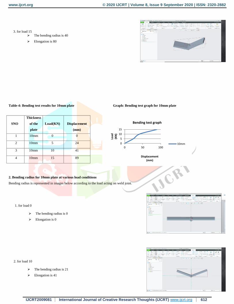
Table-4: Bending test results for 10mm plate Graph: Bending test graph for 10mm plate
SNO
Thickness
of the
plate
Load(KN)
Displacement
(mm)
1 10mm 0 0
2 10mm 5 24
3 10mm 10 41
4 10mm 15 89
2. Bending radius for 10mm plate at various load conditions
Bending radius is represented in images below according to the load acting on weld joint.
3. for load 15 The bending radius is 40
Elongation is 80
0
5
10
15
0 50 100
Load
(KN
)
Displacement(mm)
Bending test graph
10mm
1. for load 0
The bending radius is 0
Elongation is 0
For load 0
The bending radius is 0
2. for load 10
The bending radius is 21
Elongation is 41
For load 0
The bending radius is 0
www.ijcrt.org © 2020 IJCRT | Volume 8, Issue 9 September 2020 | ISSN: 2320-2882
IJCRT2009081 International Journal of Creative Research Thoughts (IJCRT) www.ijcrt.org 613
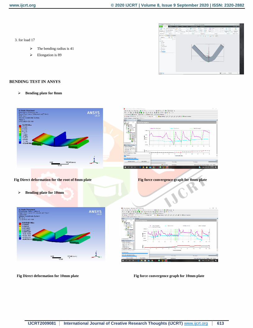
BENDING TEST IN ANSYS
Bending plate for 8mm
Fig Direct deformation for the root of 8mm plate Fig force convergence graph for 8mm plate
Bending plate for 10mm
Fig Direct deformation for 10mm plate Fig force convergence graph for 10mm plate
3. for load 17
The bending radius is 41
Elongation is 89
For load 0
The bending radius is 0
www.ijcrt.org © 2020 IJCRT | Volume 8, Issue 9 September 2020 | ISSN: 2320-2882
IJCRT2009081 International Journal of Creative Research Thoughts (IJCRT) www.ijcrt.org 614
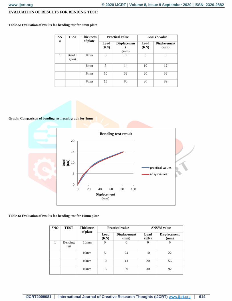
EVALUATION OF RESULTS FOR BENDING TEST:
Table-5: Evaluation of results for bending test for 8mm plate
SN
O
TEST Thickness
of plate
Practical value ANSYS value
Load
(KN)
Displacemen
t
(mm)
Load
(KN)
Displacement
(mm)
1 Bendin
g test
8mm 0 0 0 0
8mm 5 14 10 12
8mm 10 33 20 36
8mm 15 80 30 82
Graph: Comparison of bending test result graph for 8mm
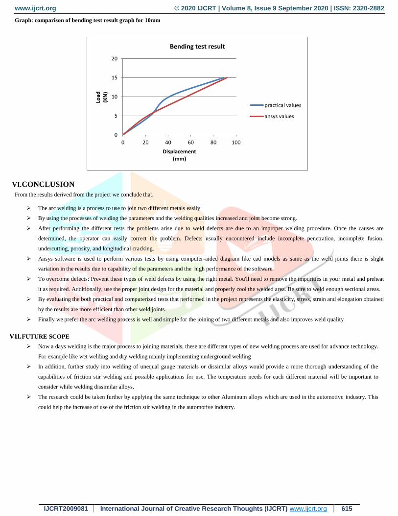
Table-6: Evaluation of results for bending test for 10mm plate
SNO TEST Thickness
of plate
Practical value ANSYS value
Load
(KN)
Displacement
(mm)
Load
(KN)
Displacement
(mm)
1 Bending test
10mm 0 0 0 0
10mm 5 24 10 22
10mm 10 41 20 56
10mm 15 89 30 92
0
5
10
15
20
0 20 40 60 80 100
Load
(KN
)
Displacement(mm)
Bending test result
practical values
ansys values
www.ijcrt.org © 2020 IJCRT | Volume 8, Issue 9 September 2020 | ISSN: 2320-2882
IJCRT2009081 International Journal of Creative Research Thoughts (IJCRT) www.ijcrt.org 615
Graph: comparison of bending test result graph for 10mm
VI.CONCLUSION
From the results derived from the project we conclude that.
The arc welding is a process to use to join two different metals easily
By using the processes of welding the parameters and the welding qualities increased and joint become strong.
After performing the different tests the problems arise due to weld defects are due to an improper welding procedure. Once the causes are
determined, the operator can easily correct the problem. Defects usually encountered include incomplete penetration, incomplete fusion,
undercutting, porosity, and longitudinal cracking.
Ansys software is used to perform various tests by using computer-aided diagram like cad models as same as the weld joints there is slight
variation in the results due to capability of the parameters and the high performance of the software.
To overcome defects: Prevent these types of weld defects by using the right metal. You'll need to remove the impurities in your metal and preheat
it as required. Additionally, use the proper joint design for the material and properly cool the welded area. Be sure to weld enough sectional areas.
By evaluating the both practical and computerized tests that performed in the project represents the elasticity, stress, strain and elongation obtained
by the results are more efficient than other weld joints.
Finally we prefer the arc welding process is well and simple for the joining of two different metals and also improves weld quality
VII.FUTURE SCOPE
Now a days welding is the major process to joining materials, these are different types of new welding process are used for advance technology.
For example like wet welding and dry welding mainly implementing underground welding
In addition, further study into welding of unequal gauge materials or dissimilar alloys would provide a more thorough understanding of the
capabilities of friction stir welding and possible applications for use. The temperature needs for each different material will be important to
consider while welding dissimilar alloys.
The research could be taken further by applying the same technique to other Aluminum alloys which are used in the automotive industry. This
could help the increase of use of the friction stir welding in the automotive industry.
0
5
10
15
20
0 20 40 60 80 100
Load
(KN
)
Displacement(mm)
Bending test result
practical values
ansys values

www.ijcrt.org © 2020 IJCRT | Volume 8, Issue 9 September 2020 | ISSN: 2320-2882
IJCRT2009081 International Journal of Creative Research Thoughts (IJCRT) www.ijcrt.org 616
VIII.REFERENCES
1) https://www.britannica.com/technology/welding
2) https://www.britannica.com/technology/welding#ref7847
3) https://www.adhesiveandglue.com/destructive-testing.html
4) https://www.ndeed.org/EducationResources/CommunityCollege/PenetrantTest/PTMateria ls/surfaceenergy.htm
5) https://www.twi-global.com/what-we-do/services-and-support/asset-management/non- destructive- testing/ndt-techniques/radiography-testing
6) https://www.caltec.ca/about-us/blog/4-main-types-ndt-testing
7) Tejpal singh, arivendhar singh, sumith saini, effect of groove design on mechanical properties of SMAW joints.vol25:665-669(2015)
8) Rouhollah Mohsen pezeshkian, peyaman shayanfar, groove angle influence on mechanical and microstructural properties of P460 steel in SMAW.
Vol27:586-598(2010)
9) Saiedeh Safaiepour, experimental study of shielded arc metal welding parameter on weld strength for AISI1020.vol26:1252-1265(2011)
10) Ipek, Elaldi analysis of welding groove angle and geometry on strength of armour steelvol.27:1437-1447(2012)
11) Ling, Fuh, Huang, Wu groove configuration of a flux cored arc welding processes, the international journal of advanced manufacturing
technology.vol25:366-375(2012)
12) Bekir Cevich analysis of welding groove configuration of the strength of S275 structural steel welded by SMAW, vol.30:224-240(2010)
13) Li, orme, yu, effect of joint design on mechanical properties of AI7075 weldment, journals of materials engineering and performance. Vol14:322-
326(2012)
14) Kaya, kahraman, durgutlu, gulench investigation of mechanical properties of different thickness of the the grade A ship plate joined by submerged
arc welding. Vol24:633-640(2010)