Embed Size (px)
Citation preview
Design and fabrication of all-solid-state rechargeable lithium batteries using
ceramic electrolytes
Hirokazu Munakata, Jungo Wakasugi, Keisuke AndoMao Shoji, Kiyoshi Kanamura
Tokyo Metropolitan UniversityTOKYO METROPOLITAN UNIVERSITYTOKYO METROPOLITAN UNIVERSITYTOKYO METROPOLITAN UNIVERSITYTOKYO METROPOLITAN UNIVERSITY
International Symposium on Electrical Fatigue in Functional MaterialsSeptember 15, 2014
Sellin, Rügen, Germany
2
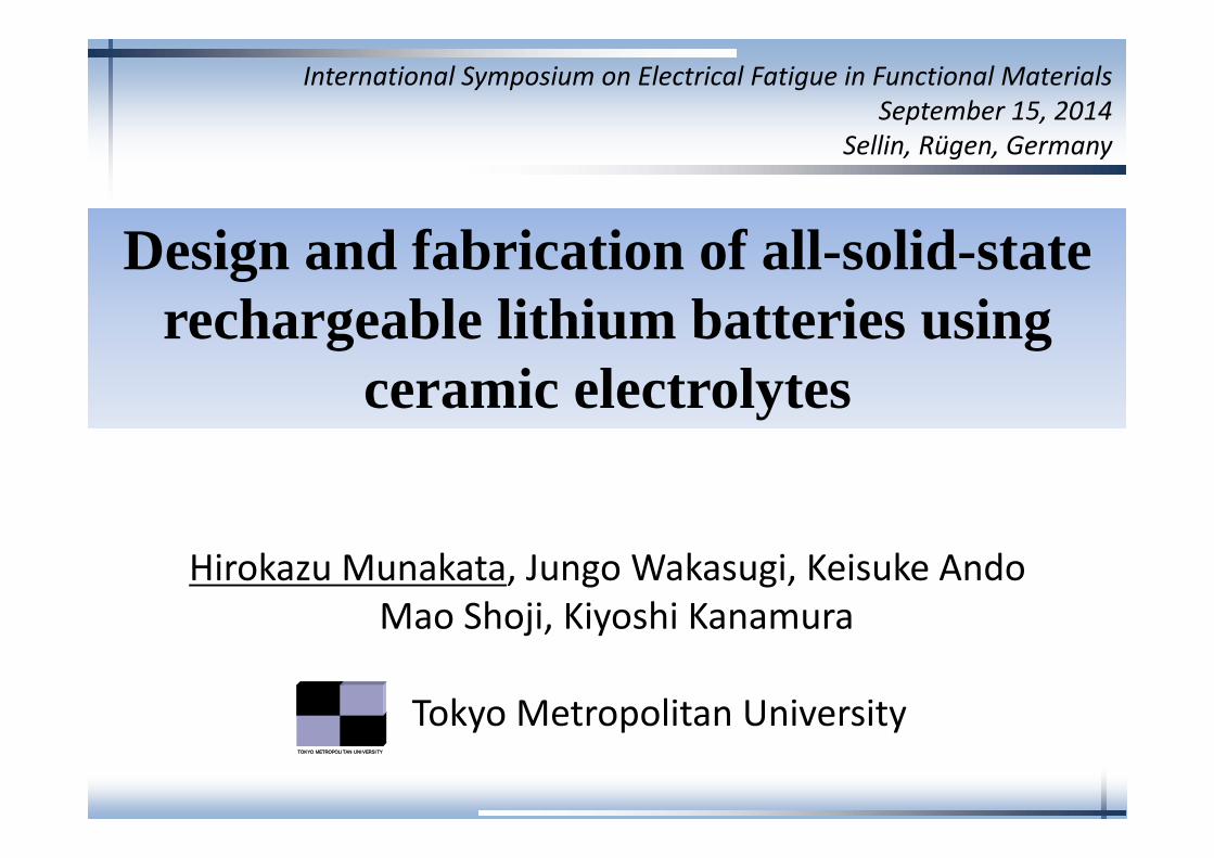
Outline1. Introduction
> Why all-solid-state?> Tasks in the development of all-solid-state batteries
2. Strategy (cell design)> 3D structured solid electrolyte> Sol-gel technique to construct a good electrode/electrolyte interface
3. Cell performance> All-solid-state rechargeable lithium battery using LLT
> All-solid-state rechargeable lithium battery using LLZ
4. Conclusions
3
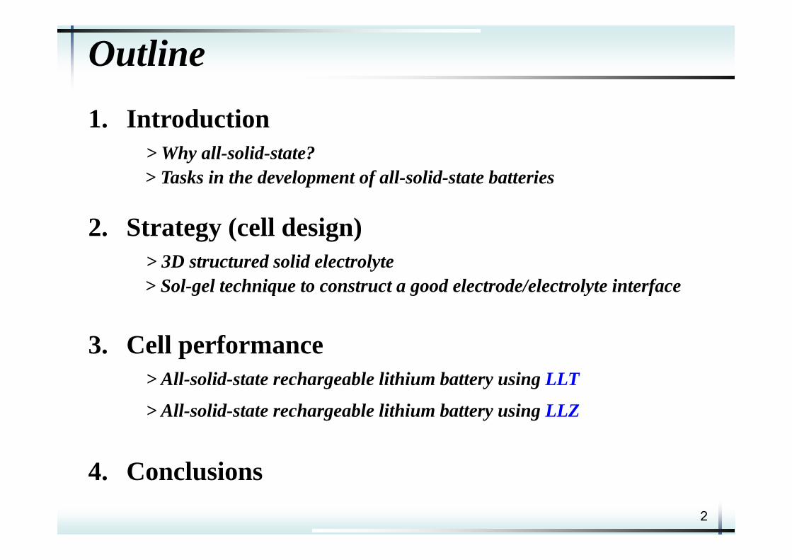
Extending applications of LIBs
Portable electronic devices Electric vehicle
SafetyEnergy densityPower density
The safety is more important in large-scale batteries.
4
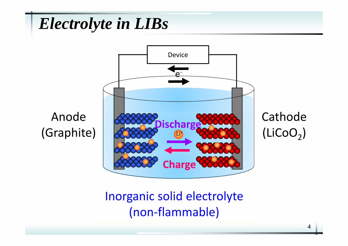
Electrolyte in LIBs
Charge
DischargeLi+
Anode(Graphite)
Cathode(LiCoO2)
Device
e‐
Liquid electrolyte(flammable organic solvents)Inorganic solid electrolyte
(non‐flammable)
5
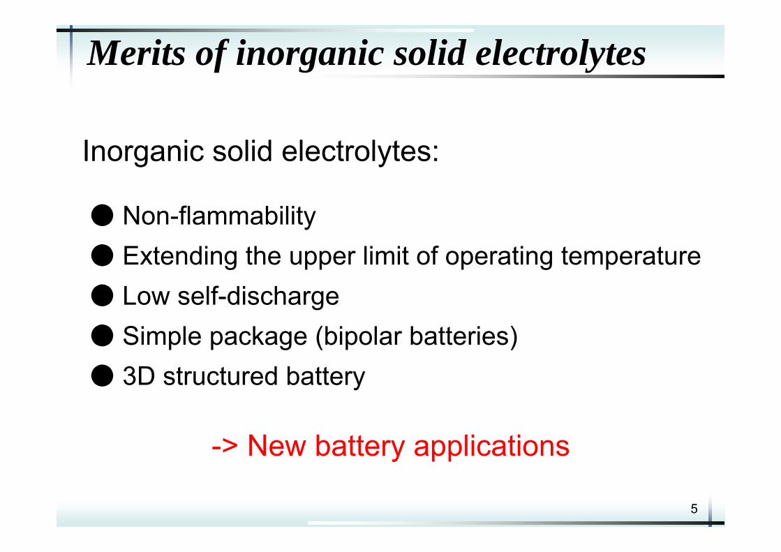
Merits of inorganic solid electrolytes
Inorganic solid electrolytes:
● Non-flammability● Extending the upper limit of operating temperature● Low self-discharge● Simple package (bipolar batteries)● 3D structured battery
-> New battery applications
6
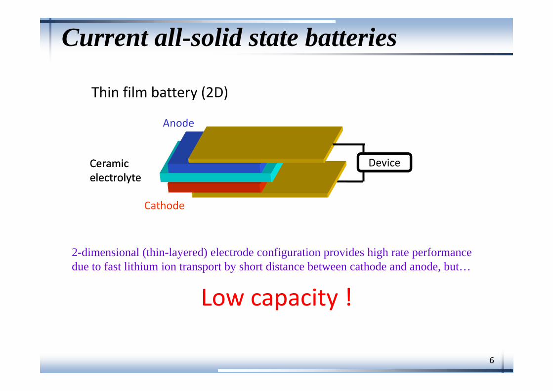
Current all-solid state batteries
Cathode
Anode
CeramicelectrolyteCeramicelectrolyte
Thin film battery (2D)
Device
2-dimensional (thin-layered) electrode configuration provides high rate performance due to fast lithium ion transport by short distance between cathode and anode, but…
Low capacity !
7
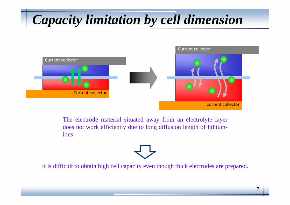
Capacity limitation by cell dimension
The electrode material situated away from an electrolyte layerdoes not work efficiently due to long diffusion length of lithium-ions.
Current collector
Current collector
Current collector
Current collector
It is difficult to obtain high cell capacity even though thick electrodes are prepared.
8
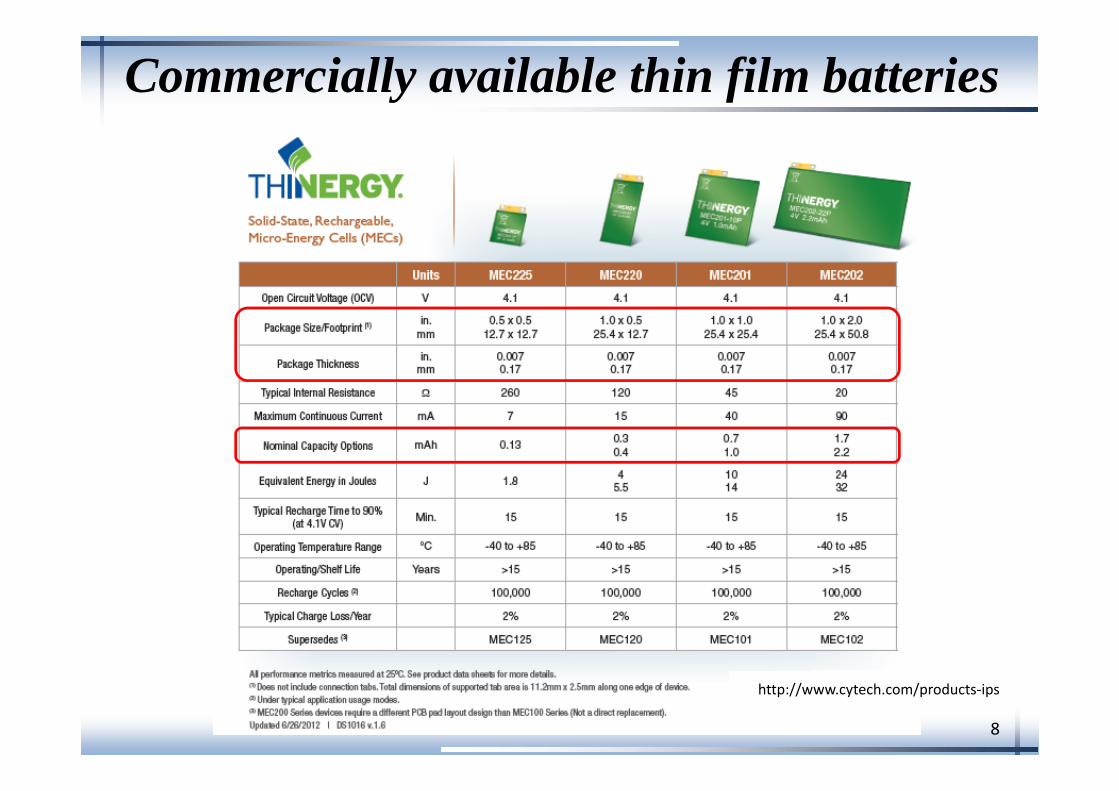
http://www.cytech.com/products‐ips
Commercially available thin film batteries
9
3D electrode configuration
Current collector
Current collector
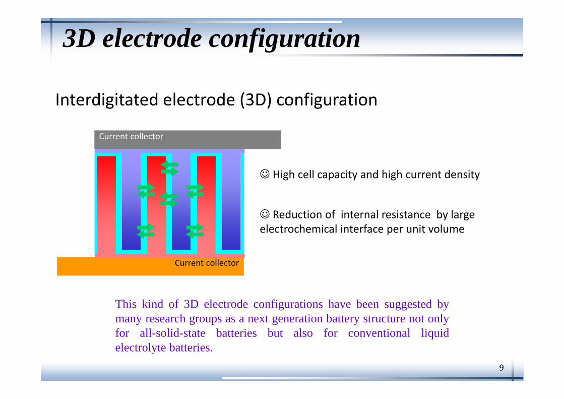
Interdigitated electrode (3D) configuration
High cell capacity and high current density
Reduction of internal resistance by large electrochemical interface per unit volume
The distance between anode and cathode can be maintainedconstantly even when the amounts of electrode materials areincreased.
This kind of 3D electrode configurations have been suggested bymany research groups as a next generation battery structure not onlyfor all-solid-state batteries but also for conventional liquidelectrolyte batteries.
10
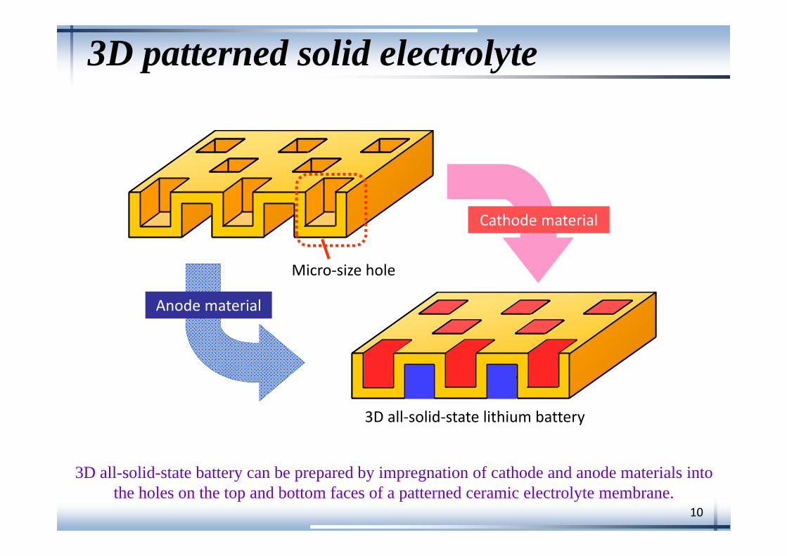
3D patterned solid electrolyte
Micro‐size hole
Cathode material
Anode material
3D all‐solid‐state lithium battery
3D all-solid-state battery can be prepared by impregnation of cathode and anode materials into the holes on the top and bottom faces of a patterned ceramic electrolyte membrane.
11
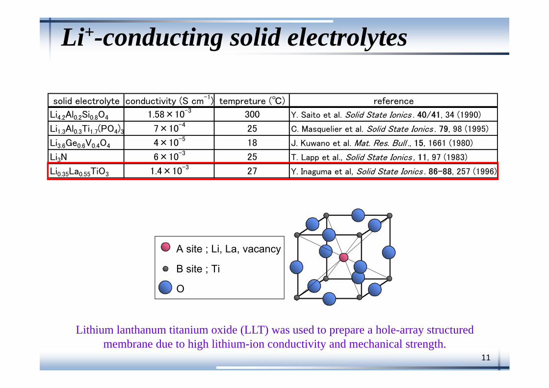
Li+-conducting solid electrolytes
solid electrolyte conductivity (S cm-1) tempreture (℃) reference
Li4.2Al0.2Si0.8O4 1.58×10⁻³ 300 Y. Saito et al. Solid State Ionics . 40/41, 34 (1990)
Li1.3Al0.3Ti1.7(PO4)3 7×10⁻⁴ 25 C. Masquelier et al. Solid State Ionics . 79, 98 (1995)
Li3.6Ge0.6V0.4O4 4×10⁻⁵ 18 J. Kuwano et al. Mat. Res. Bull ., 15, 1661 (1980)
Li3N 6×10⁻³ 25 T. Lapp et al., Solid State Ionics , 11, 97 (1983)
Li0.35La0.55TiO3 1.4×10⁻³ 27 Y. Inaguma et al, Solid State Ionics . 86-88, 257 (1996)
O
A site ; Li, La, vacancy
B site ; Ti
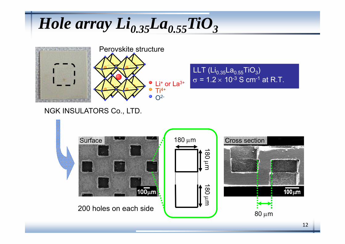
Lithium lanthanum titanium oxide (LLT) was used to prepare a hole-array structured membrane due to high lithium-ion conductivity and mechanical strength.
12
Hole array Li0.35La0.55TiO3
NGK INSULATORS Co., LTD.
Surface
LLT (Li0.35La0.55TiO3) = 1.2 10-3 S cm-1 at R.T.LLT (Li0.35La0.55TiO3) = 1.2 10-3 S cm-1 at R.T.
Perovskite structure
Li+ or La3+
Ti4+
O2-
Cross section180 m
180 m180 m
80 m200 holes on each side
13
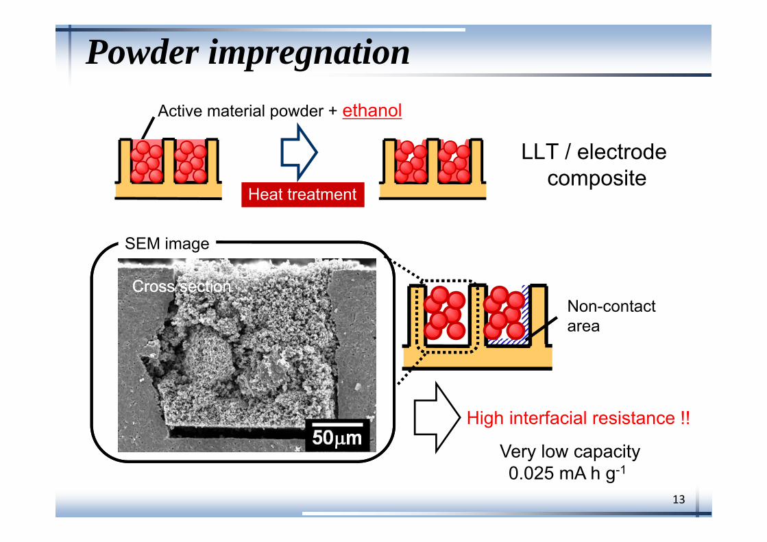
Powder impregnation
Cross sectionCross sectionNon-contactarea
SEM image
Active material powder + ethanol
Heat treatmentHeat treatment
High interfacial resistance !!
Very low capacity0.025 mA h g-1
LLT / electrodecomposite
14
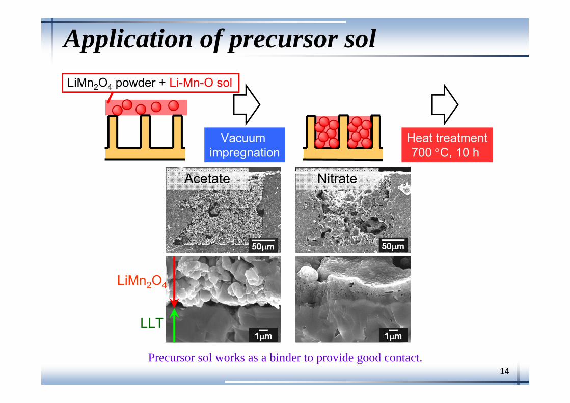
Application of precursor sol
LLT
LiMn2O4
Acetate Nitrate
Vacuum impregnation
Heat treatment700 C, 10 h
LiMn2O4 powder + Li-Mn-O sol
Precursor sol works as a binder to provide good contact.
15
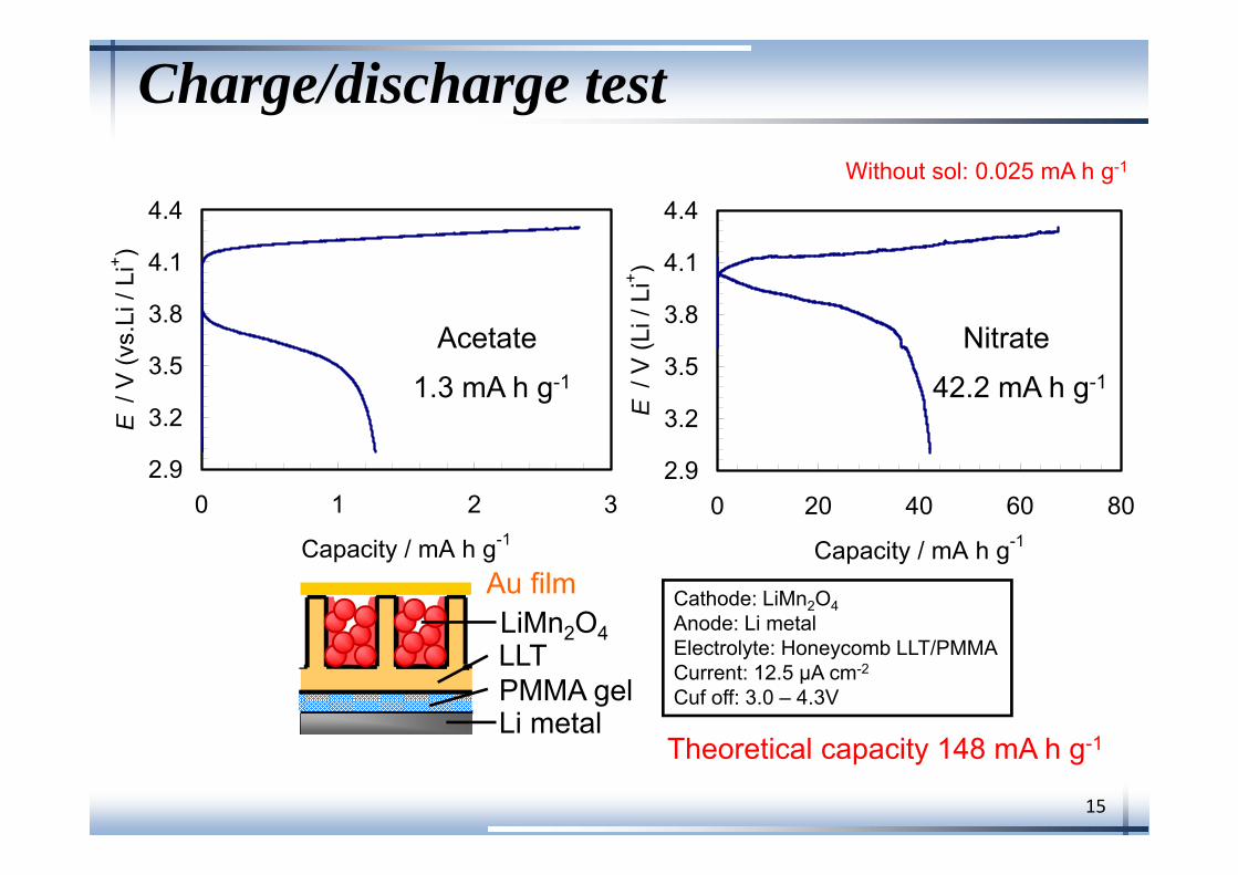
Charge/discharge test
2.9
3.2
3.5
3.8
4.1
4.4
0 1 2 3
Capacity / mA h g-1
E /
V (v
s.Li
/ Li
+ )
2.9
3.2
3.5
3.8
4.1
4.4
0 20 40 60 80
Capacity / mA h g-1
E /
V (L
i / L
i+ )
1.3 mA h g-1 42.2 mA h g-1
Acetate Nitrate
Cathode: LiMn2O4Anode: Li metalElectrolyte: Honeycomb LLT/PMMACurrent: 12.5 μA cm-2
Cuf off: 3.0 – 4.3V
LiMn2O4
PMMA gelLi metal
LLT
Au film
Theoretical capacity 148 mA h g-1
Without sol: 0.025 mA h g-1
16
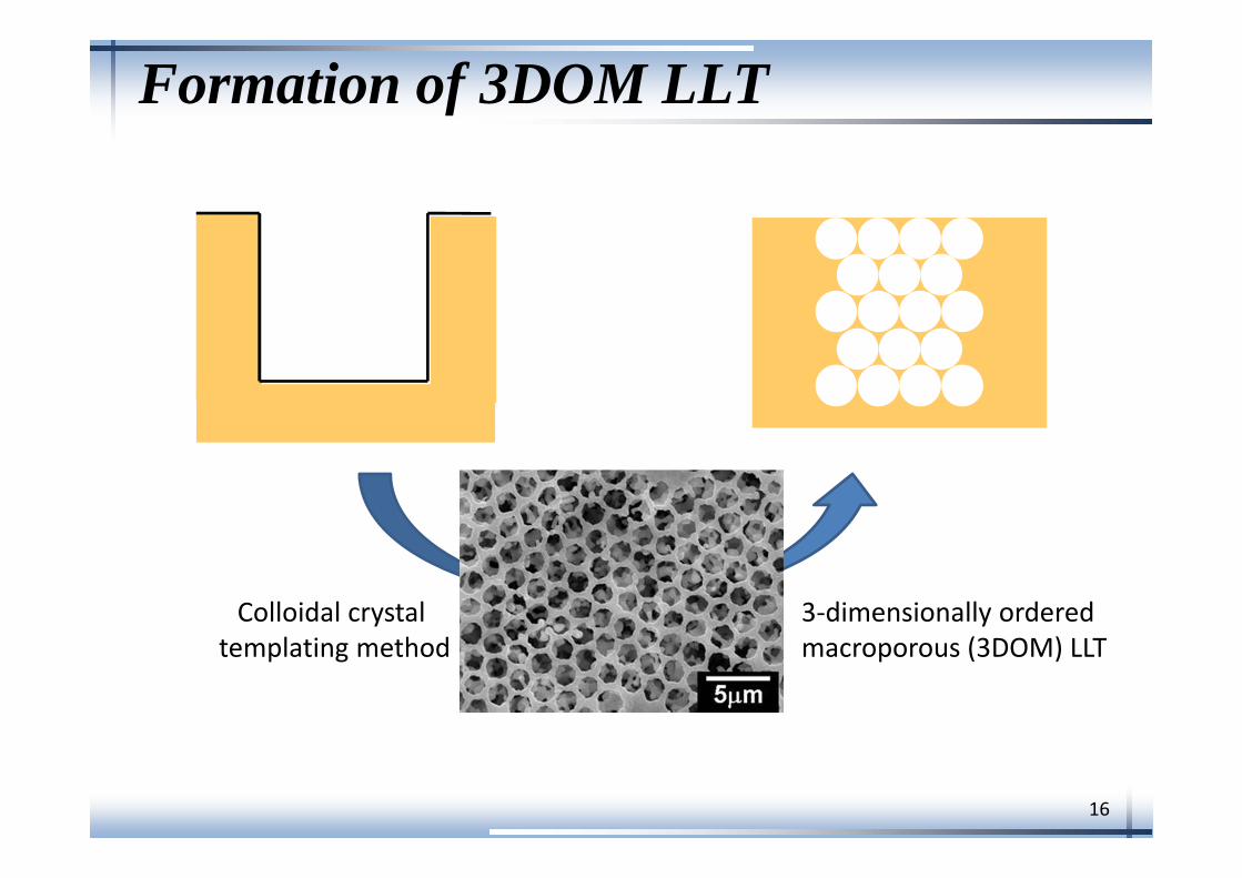
Formation of 3DOM LLT
3‐dimensionally ordered macroporous (3DOM) LLT
Colloidal crystaltemplating method
17
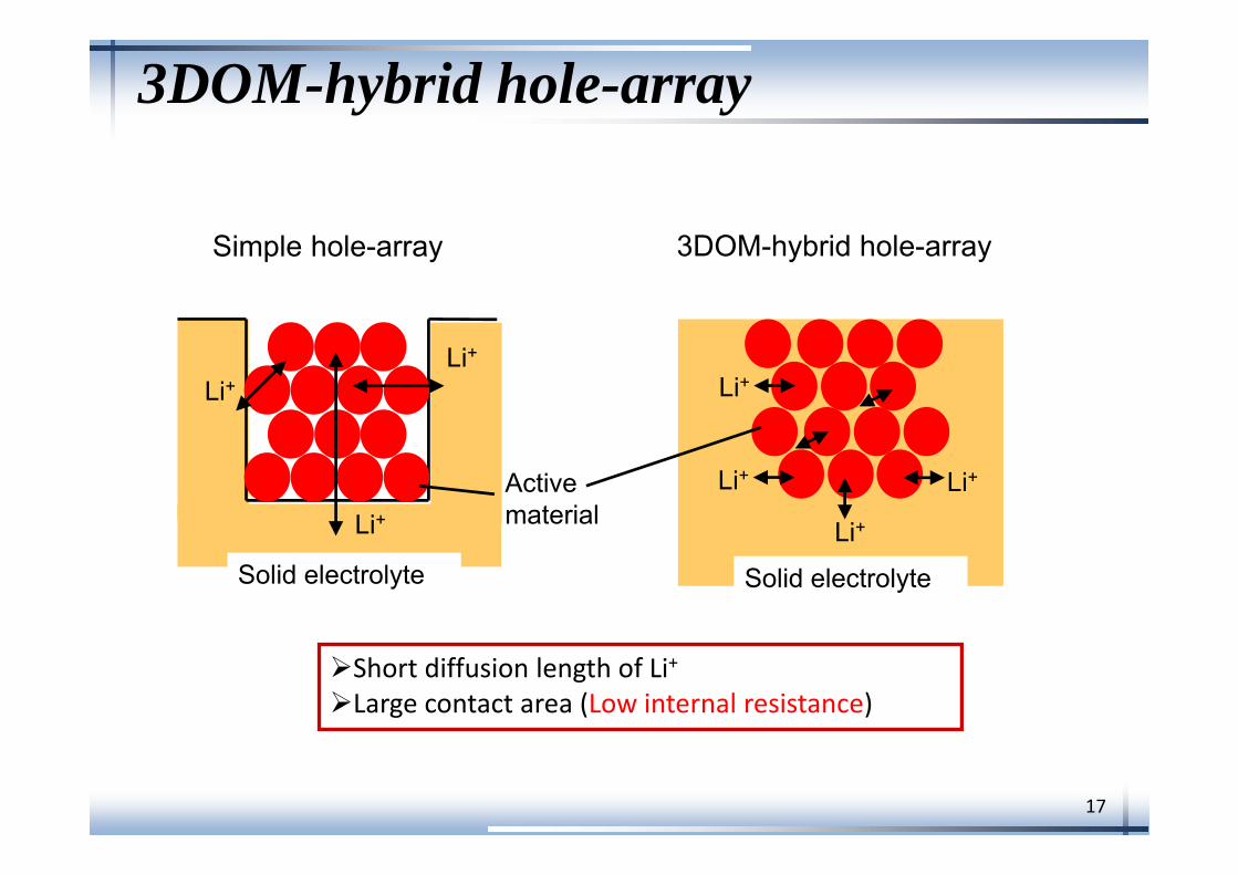
3DOM-hybrid hole-array
Short diffusion length of Li+Large contact area (Low internal resistance)
Li+
Simple hole-array 3DOM-hybrid hole-array
Li+Li+
Li+
Li+Li+
Solid electrolyte Solid electrolyte
Active material
Li+
18
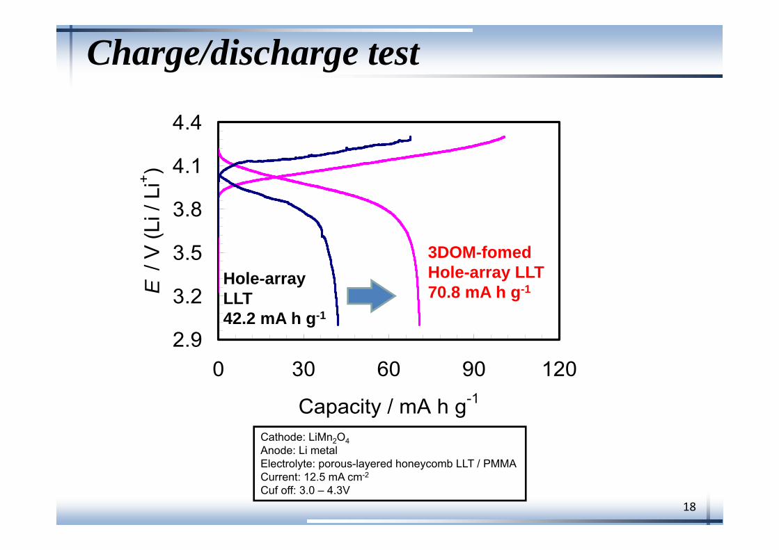
Charge/discharge test
2.9
3.2
3.5
3.8
4.1
4.4
0 30 60 90 120
Capacity / mA h g-1
E /
V (L
i / L
i+ )
Cathode: LiMn2O4Anode: Li metalElectrolyte: porous-layered honeycomb LLT / PMMACurrent: 12.5 mA cm-2
Cuf off: 3.0 – 4.3V
3DOM-fomed Hole-array LLT70.8 mA h g-1
Hole-array LLT42.2 mA h g-1
19
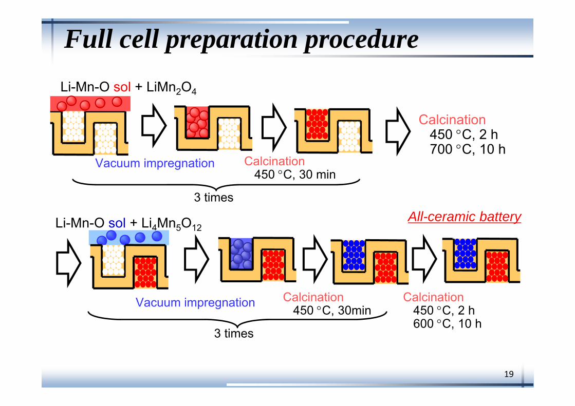
Full cell preparation procedure
Calcination450 C, 30 min
Calcination450 C, 2 h600 C, 10 h
Vacuum impregnation
Li-Mn-O sol + LiMn2O4
Li-Mn-O sol + Li4Mn5O12
Vacuum impregnation
All-ceramic battery
Calcination450 C, 2 h700 C, 10 h
Calcination450 C, 30min
3 times
3 times
20
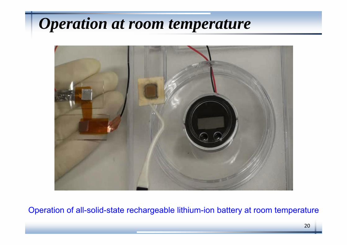
Operation at room temperature
Operation of all-solid-state rechargeable lithium-ion battery at room temperature
21
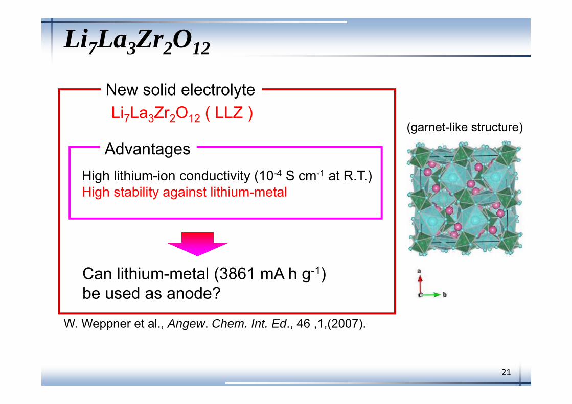
Li7La3Zr2O12
Li7La3Zr2O12 ( LLZ )
W. Weppner et al., Angew. Chem. Int. Ed., 46 ,1,(2007).
High lithium-ion conductivity (10-4 S cm-1 at R.T.)High stability against lithium-metal
Can lithium-metal (3861 mA h g-1)be used as anode?
New solid electrolyte
Advantages(garnet-like structure)
22
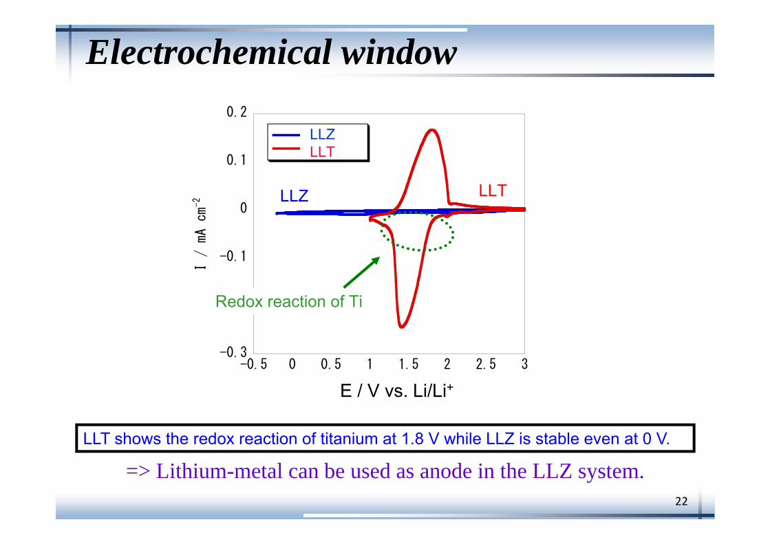
Electrochemical window
LLTLLZ
-0.3
-0.2
-0.1
0
0.1
0.2
-0.5 0 0.5 1 1.5 2 2.5 3
1st cycle2nd cycle
I / mA cm-2
E / V
LLZLLT
Redox reaction of Ti
LLT shows the redox reaction of titanium at 1.8 V while LLZ is stable even at 0 V.
E / V vs. Li/Li+
=> Lithium-metal can be used as anode in the LLZ system.
23
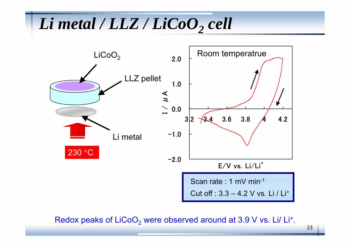
Li metal / LLZ / LiCoO2 cell
-2.0
-1.0
0.0
1.0
2.0
3.2 3.4 3.6 3.8 4 4.2
E/V vs. Li/Li+I
/ μ
A
Room temperatrue
Scan rate : 1 mV min-1
Cut off : 3.3 – 4.2 V vs. Li / Li+
LLZ pellet
LiCoO2
Li metal
230 C
Redox peaks of LiCoO2 were observed around at 3.9 V vs. Li/ Li+.
24
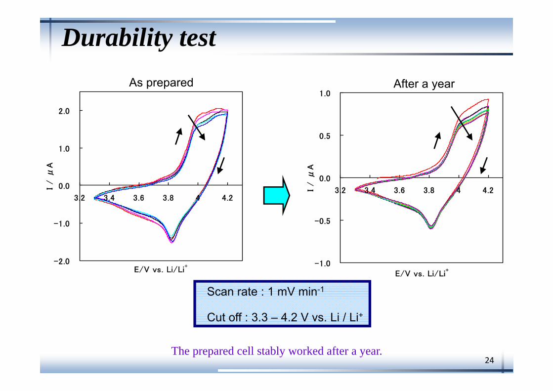
Durability test
-1.0
-0.5
0.0
0.5
1.0
3.2 3.4 3.6 3.8 4 4.2
E/V vs. Li/Li+
I / μ
A
-2.0
-1.0
0.0
1.0
2.0
3.2 3.4 3.6 3.8 4 4.2
E/V vs. Li/Li+
I / μ
A
After a yearAs prepared
Scan rate : 1 mV min-1
Cut off : 3.3 – 4.2 V vs. Li / Li+
The prepared cell stably worked after a year.
25
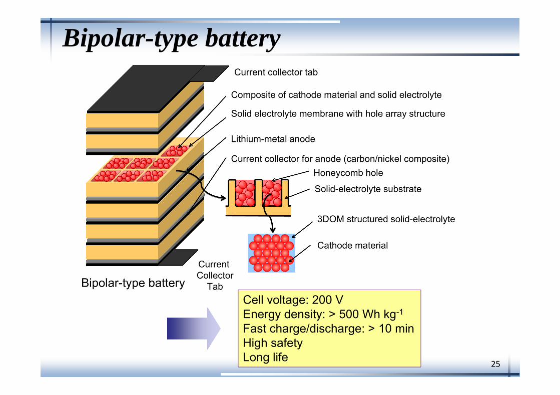
Bipolar-type battery
Bipolar-type battery
Current collector tab
Composite of cathode material and solid electrolyte
Solid electrolyte membrane with hole array structure
Lithium-metal anode
Current collector for anode (carbon/nickel composite)
Cathode material
3DOM structured solid-electrolyte
Honeycomb hole
Solid-electrolyte substrate
Current Collector
TabCell voltage: 200 VEnergy density: > 500 Wh kg-1
Fast charge/discharge: > 10 minHigh safetyLong life
26
0
500
1000
1500
2000
0 250 500 750 1000
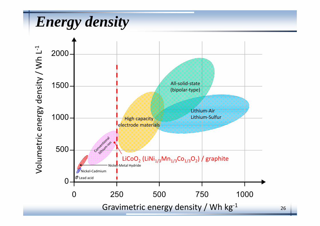
Lead acid
Nickel‐CadmiumNickel‐Metal Hydride
Gravimetric energy density / Wh kg‐1
Volumetric
ene
rgy de
nsity
/ WhL‐1
LiCoO2 (LiNi1/3Mn1/3Co1/3O2) / graphite
High capacityelectrode materials
All‐solid‐state(bipolar‐type)
Lithium‐AirLithium‐Sulfur
Energy density
27
Conclusions
3D electrode configuration is one of prospective ways toimprove the performance of all-solid-state rechargeablelithium batteries.
For further improvement of cell performance, the following developments areneeded:
• Higher aspect ratio in 3D electrode configuration
• Optimization of electrolyte/electrode interface
• Cell stacking for bipolar-type all-solid-state battery