Embed Size (px)
Citation preview
DESIGN AND FABRICATION OF SHEAR TEST RIG FOR SANDWICH CORES
DAHRUL AKMA BIN MOHD SABRI
A project submitted in partial fulfilment of the
requirement for the award of the Diploma
of Mechanical Engineering
Faculty of Mechanical Engineering
Universiti Malaysia Pahang
NOVEMBER 2007
ABSTRACT
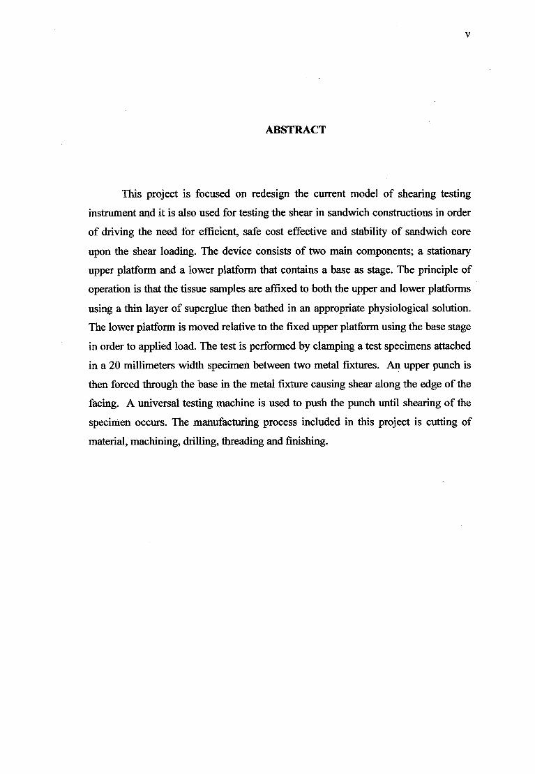
This project is focused on redesign the current model of shearing testing
instrument and it is also used for testing the shear in sandwich constructions in order
of driving the need for efficient, sale cost effective and stability of sandwich core
upon the shear loading. The device consists of two main components; a stationary
upper platform and a lower platform that contains a base as stage. The principle of
operation is that the tissue samples are affixed to both the upper and lower platforms
using a thin layer of superglue then bathed in an appropriate physiological solution.
The lower platform is moved relative to the fixed upper platform using the base stage
in order to applied load. The test is performed by clamping a test specimens attached
in a 20 millimeters width specimen between two metal fixtures. An upper punch is
then forced through the base in the metal fixture causing shear along the edge of the
facing. A universal testing machine is used to push the punch until shearing of the
specimen occurs. The manufacturing process included in this project is cutting of
material, machining, drilling, threading and finishing.
V
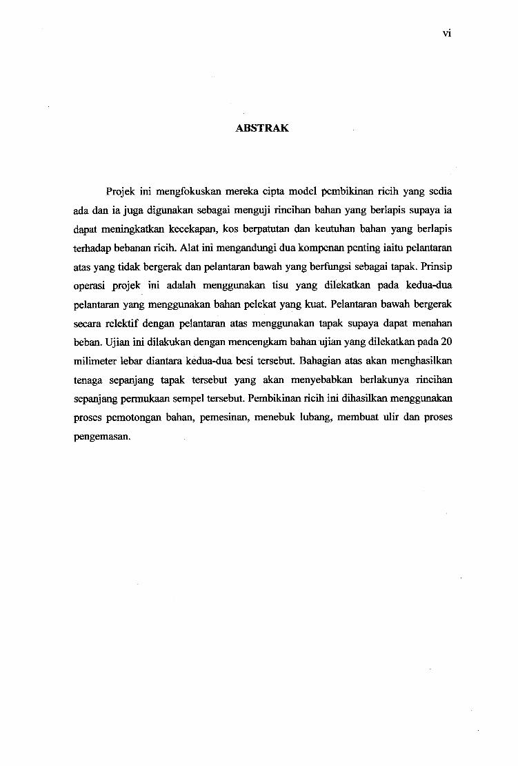
ABSTRAK
Projek mi mengfokuskan mçreka cipta model pembikinan ricih yang sedia
ada dan ia juga digunakan sebagai menguji rincihan bahan yang berlapis supaya ia
dapat meningkatkan kecekapan, kos berpatutan dan keutuhan bahan yang berlapis
terhadap bebanan ricih. Alat mi mengandungi dua kompenan penting iaitu pelantaran
atas yang tidak bergerak dan pelantaran bawah yang berfungsi sebagai tapak. Prinsip
operasi projek mi adalah menggunakan tisu yang dilekatkan pada kedua-dua
pelantaran yang menggunakan bahan pelekat yang kuat. Pelantaran bawah bergerak
secara relektif dengan pelantaran atas menggunakan tapak supaya dapat menahan
beban. Ujian mi dilakukan dengan mencengkam bahan ujian yang dilekatkan pada 20
milimeter lebar diantara kedua-dua besi tersebut. Bahagian atas akan menghasilkan
tenaga sepanjang tapak tersebut yang akan menyebabkan berlakunya rincihan
sepanjang permukaan sempel tersebut. Pembikinan ricih mi dihasilkan menggunakan
proses pemotongan bahan, pemesinan, menebuk lubang, membuat ulir dan proses
pengemasan.
kill I
TABLE OF CONTENTS
CHAPTER TITLE PAGE
DECLARATION
DEDICATION
ACKNOWLEDGEMENTS iv
ABSTRACT v
ABSTRAK vi
TABLE OF CONTENTS vii
LIST OF FIGURES x
LIST OF APPENDICES xii
1 INTRODUCTION
1.1 Project Synopsis 1
1.2 Problem Statement 1
1.3 Project Objective 2
1.4 Project Scope 2
1.5 Project Flow Chart 3
1.6 Project Planning 4
2 LITERATURE REVIEW
2.1 Introduction 6
2.2 Paper Review 7
2.2.1 American Society for Testing 7 and Materials (ASTM) C273
2.2.2 The Sandwich Concept 8
vii
vii'
3
4
2.3 General Formula of Shear Test Rig 10
2.4 Current Technology 11
2.4.1 Shear Testing Rig on Deformable 11 Soft Biological Tissues
2.4.2 Shear Test in Compression Loading Mode 12
2.4.3 Concrete Beam 13
2.4.4 Direct Shear Testing 14
2.5 Milling Machine 15
2.5.1 Introduction 15
2.5.2 Types of Milling Machine 15
2.5.3 Milling Cutters 17
2.5.4 Selecting a Milling Cutter 20
2.5.5 Industrial Applications 21
PROJECT METHODOLOGY
3.1 Introduction 22
3.2 Design Selection 23
3.2.1 Propose Design 23
3.2.2 Suggestion Design Selection 25
3.2.3 Engineering Drawing for Selected Design 25
3.2.4 Detail Design 25
3.3 Material Selection 26
3.3.1 Mild Steel 26
3.3.2 Aluminium 26
FABRICATION
4.1 Introduction 27
4.2 Step By Step Processes 27
4.2.1 Cutting Material 27
4.2.2 Milling Machine Operations 28
4.2.3 Removing Chip and Drilling 32
ix
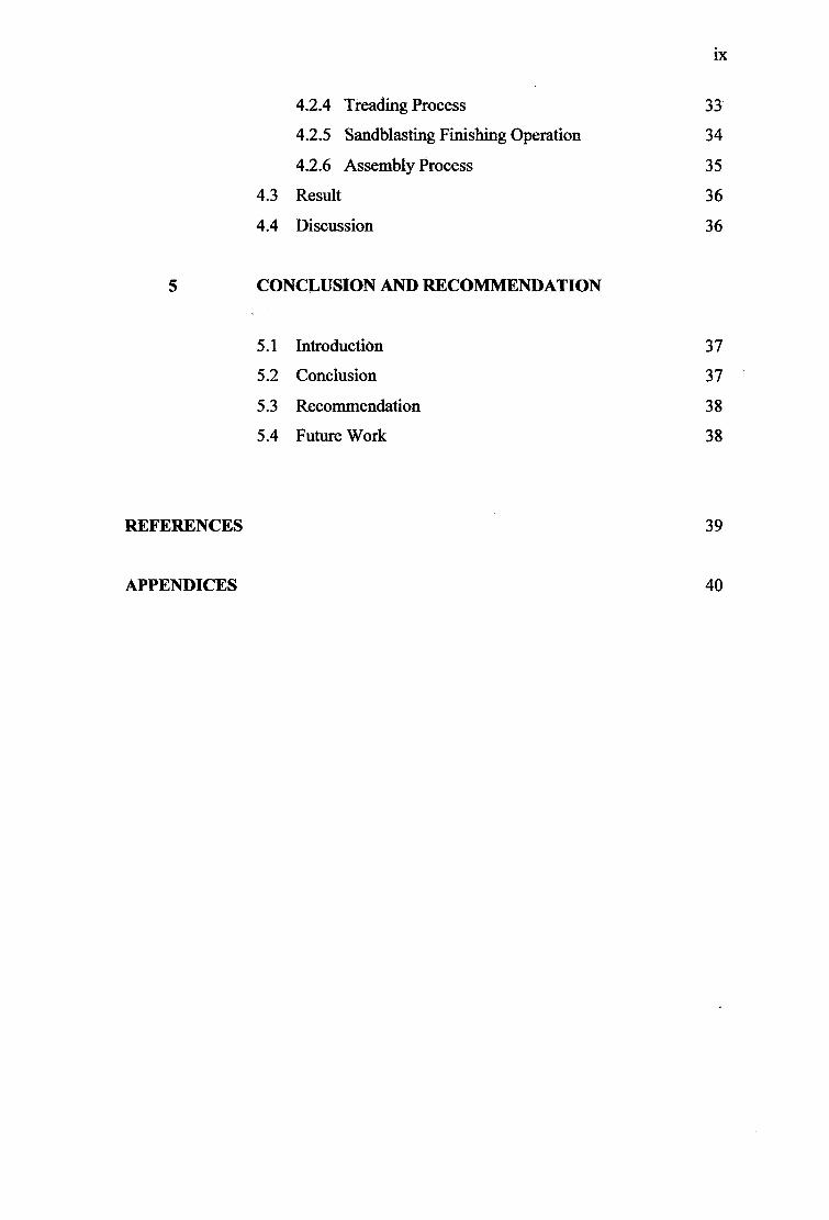
4.2.4 Treading Process 33
4.2.5 Sandblasting Finishing Operation 34
4.2.6 Assembly Process 35
4.3 Result 36
4.4 Discussion 36
5 CONCLUSION AND RECOMMENDATION
5.1 Introduction 37
5.2 Conclusion 37
5.3 Recommendation 38
5.4 Future Work 38
REFERENCES 39
APPENDICES 40
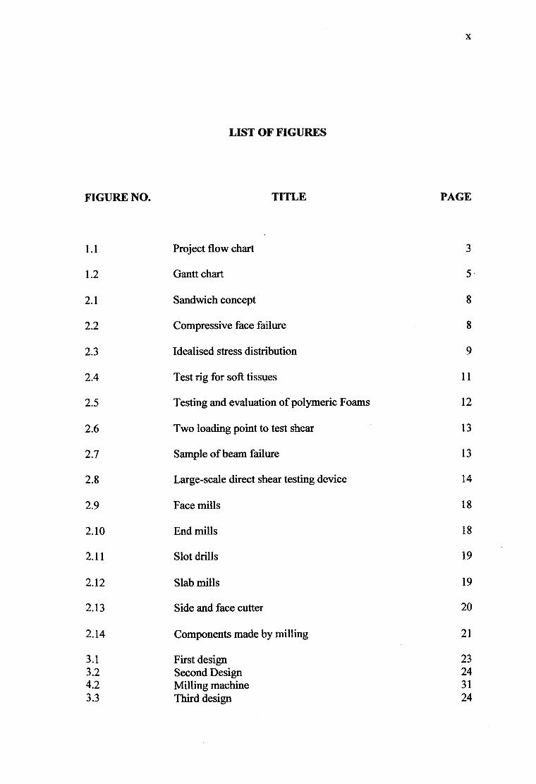
LIST OF FIGURES
FIGURE NO. TITLE PAGE
1.1 Project flow chart 3
1.2 Gantt chart 5
2.1 Sandwich concept 8
2.2 Compressive face failure 8
2.3 Idealised stress distribution 9
2.4 Test rig for soft tissues 11
2.5 Testing and evaluation of polymeric Foams 12
2.6 Two loading point to test shear 13
2.7 Sample of beam failure 13
2.8 Large-scale direct shear testing device 14
2.9 Face mills 18
2.10 End mills 18
2.11 Slot drills 19
2.12 Slab mills 19
2.13 Side and face cutter 20
2.14 Components made by milling 21
3.1 First design 23 3.2 Second Design 24 4.2 Milling machine 31 3.3 Third design 24
x

xi
4.3 Discard the chip process 32
4.4 Drilling process 32
4.5 Treading tool
33
4.6 Treading process 33
4.7 Sandblasting machine 35
4.8 Assembly process 35
xli
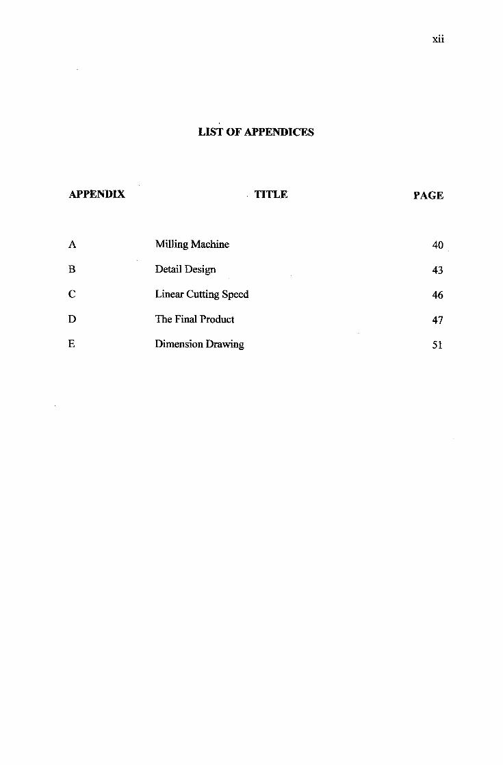
LIST OF APPENDICES
APPENDIX TITLE PAGE
A Milling Machine 40
B Detail Design 43
C Linear Cutting Speed 46
D The Final Product 47
E Dimension Drawing 51
CHAPTER 1
INTRODUCTION
1.1 Project Synopsis
Final year project is one of the subjects for this semester. In this subject, a
project needs to do to fulifi the subject requirement. The project involves designing
and fabricating an instrument for testing shear. This instrument could be use by the
other student in order to test the shear which according to the syllabus. This project
title is about Design and Fabrication of Shear Test Rig for Sandwich Cores. The
shear test is provides a standard method in obtaining data for the behaviour of the
shear strength, shear modulus and shear failure load of the cores. This project is also
to design and fabricate the shear test rig for sandwich core property according to
standard American Society for Testing and Materials (ASTM) C273. This project
also acquires the skills of design, analysis, fabrication and testing.
1.2 Problem Statement
The problem with the current shear test apparatus is:
a) The conventional shear test is difficult to handle.
b) The current design of shear test rig is expensive, not portable and
complicated to operate.
2
1.3 Project Objectives
Objectives for this project are as follows:
a) To design a basic/simple test rig for materials testing.
b) To fabricate a shear test rig in tension mode with few degrees of load
setting in sliding motion.
1.4 Project Scope of Work
Basically, this project is based on the scopes of:
a) To design and fabricate a basic/simple shear test rig for materials
testing.
b) To fabricate a shear test rig in compression mode and with few
degrees of horizontal direction (sliding) and generated by a motor.
C) The test will comply the American Society for Testing & Material
(ASTM) standard C 273.
3
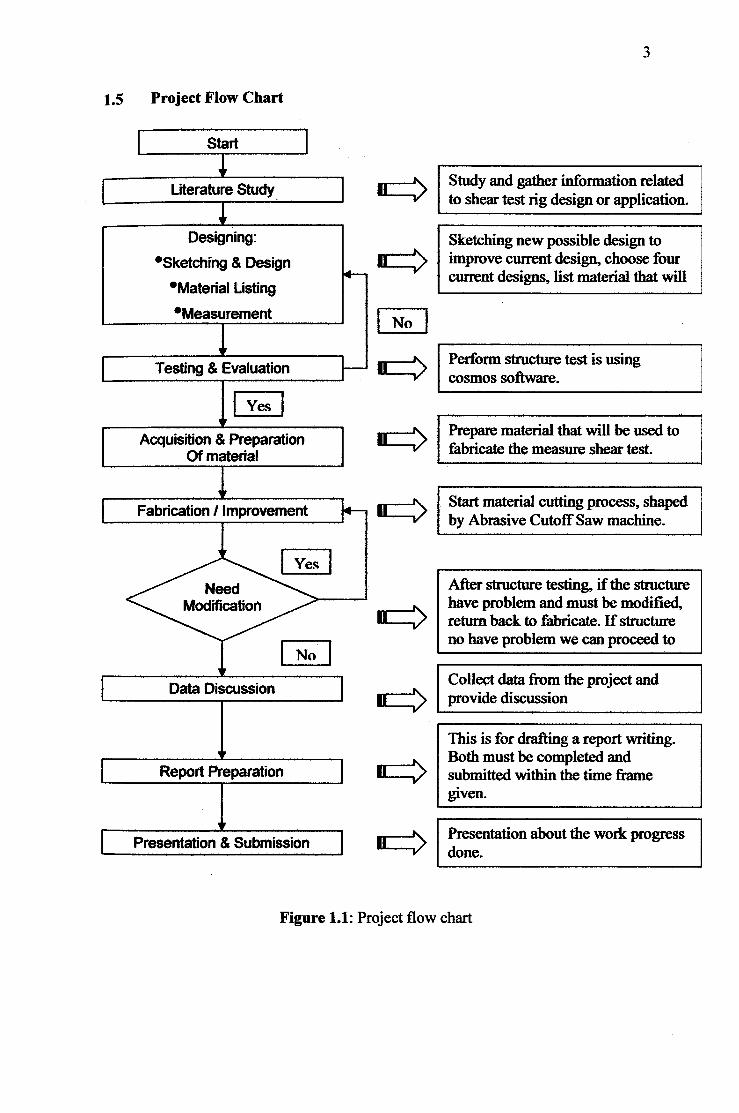
1.5 Project Flow Chart
Start
Literature Study iStudy and gather information related to shear test rig design or application.
Designing: Sketching new possible design to *Sketching & Design ii > improve current design, choose four
current designs, list material that will •Material Listing
Measurement 1 No
4 I __ Testing & Evaluation I J • > Perform structure test is using
cosmos software.
j,,iesI Acquisition & Preparation • '> Prepare material that will be used to
Of materialV fabricate the measure shear test.
' Start material cutting process, shaped Fabrication I improvement 14 ] II > by Abrasive Cutoff Saw machine.
3YesI Need After structure testing, if the structure
Modification have problem and must be modified, II return back to fabricate. If structure
I Nono have problem we can proceed to
Data Discussion I Collect data from the project and • > provide discussion
This is for drafting a report writing.
PreparationBoth must be completed and
Report PrePa ' h/ submitted within the time frame given.
Presentation & Submission • > Presentation about the work progress done.
Figure 1.1: Project flow chart
4
1.6 Project Planning
This project is start with investigation and makes a research and literature
review via internet, reference books, supervisor and other relevant academic material
that related to this project. To make this project more accurate and suitable, study
more about this topic and more than two week to make a literature review.
Beginning week, need to do some schedule management for this project
which included schedule management to all member in the group. All schedule will
be apply in a Microsoft Excel to make a Gantt chart. It takes a week to accomplish
all schedules.
Then, discuss with supervisor and continue detail research about pressure
transducer. The good sample must be chosen to make the precise calculation and
easy to take the data. The next task is preparation of progress presentation and report
writing. These tasks take two week to be finish.
Calibration process is start after midterm. And then, the testing needs to
perform. When get the data, the comparison between the actual and experiment data
must be done. This task scheduled takes several weeks to finish. Due to the some
problem that will be discuss in the other chapter, all these task still cannot be done
when this report written except the type of pressure transducer get.
Lastly, the final report writing and prepare the presentation. This takes about
one week to arrange and accomplish. A report is guided by UMP thesis format and
also guidance from supervisor. Due to all problems that student facing, the
management have agreed to extend the time to submit a report and presentation. All
task scheduled is take around fourteen weeks to complete.

DO U)
. - C
9110101010101111 0110101010101111 MINNISIM1010111111 01101010101011111 01101010101011111 011MISIMININIIIII • 01101010101011111 91101010101011111 0111101010101111-1 91111110101011111 01111010101011111 m:uiuiiiuuiuuuui
ii Dl drA
F C)
= DO
Pk
CHAPTER 2
LITERATURE REVIEW
2.1 Introduction
This project is focused on redesign the current model of shearing testing
instrument and it is also used for testing the shear in sandwich constructions in order of
driving the need for efficient, safe cost effective and stability of sandwich core upon the
shear loading. Inadequate or inappropriate is connected to produce an unsafe roof
conditions threatening both personnel safety and production capacity. Although the use
of composites in infrastructure is higher, there still need for the more comprehensive
understanding of their behavior in construction applications in order to provide some
standard design methods. Composites research and construction projects are underway
at the federal and state level, and at several universities. This project was partially
conceived of supporting those efforts.
7
2.2 Paper Review
2.2.1 American Society for Testing and Materials (ASTM) C273
This test method covers the concept of shear properties of sandwich construction
core materials associated with shear distortion of planes parallel to the facings. It covers
of shear strength parallel to the plane of the sandwich, and the shear modulus associated
with strains in a plane normal to the facings. The test may be conducted on core
materials bonded directly to the loading plates or the sandwich facings bonded to the
plates. Permissible core material forms include those with continuous bonding surfaces
(such as balsa wood and foams) as well as those with discontinuous bonding surfaces
(such as honeycomb) [1].
The value stated in either SI units or inch-pound units is to be regarded
separately as it standard. Units within of text the inch-pound units are shown in brackets.
The value stated in each system is not exact equivalents; therefore, each system must be
used independently of the other. Combining values from the two systems may result in
nonconformance with the standard [1].
This standard does not purport to address all of the -safety concerns, if any,
associated with its use. It is the responsibility of the user of this standard to establish
appropriate safety and health practices and determine the applicability of regulatory
limitations prior to use [1].
8
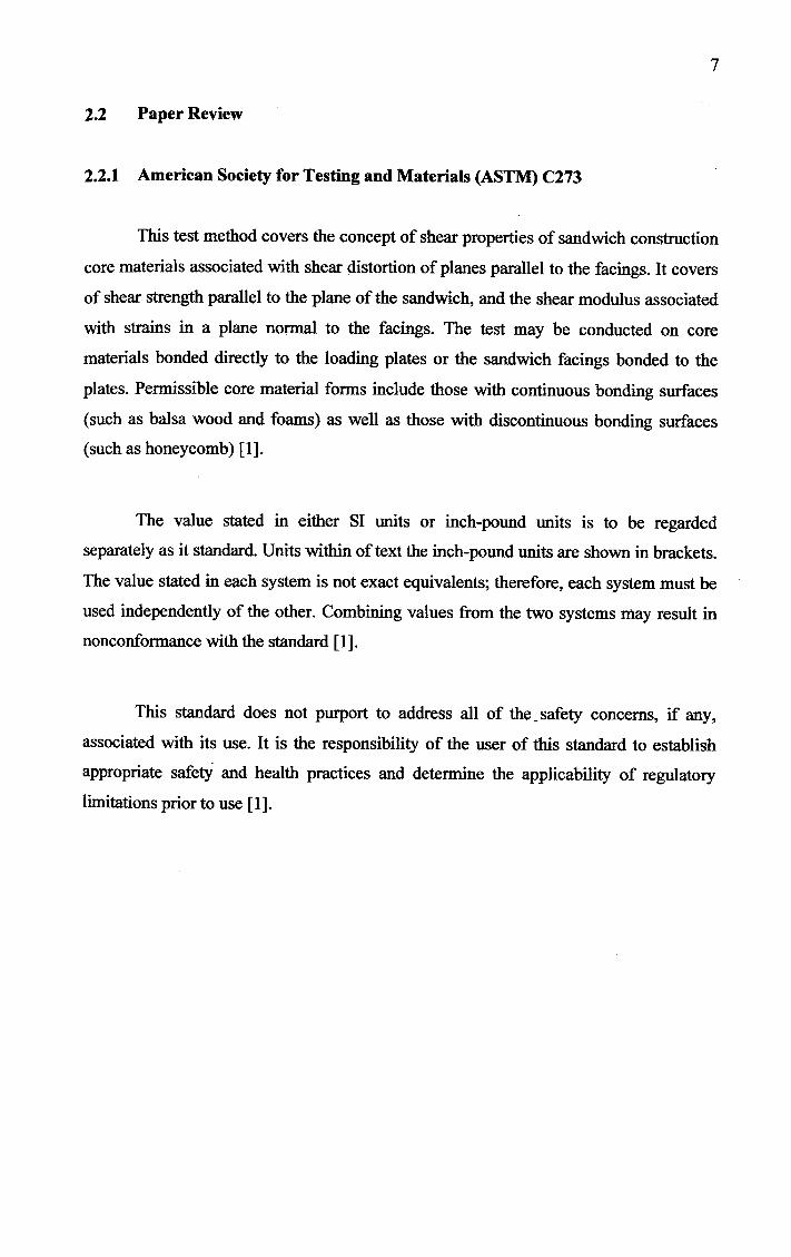
2.2.2 The Sandwich Concept
Thin, strong and stiff face sheets are separated by a thick, lightweight and
relatively compliant core. Sandwich structures provide a high bending stiffness and
strength to weight ratio. Widely applied in the field value weight is critical such as
aircraft, wind turbine blades etc [2].
Face sheez Adhesive
- Core
Figure 2.1: Sandwich concept [2]
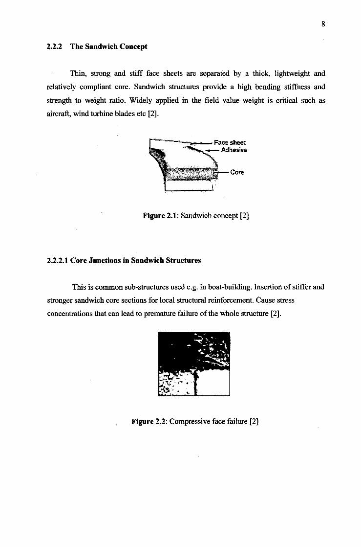
2.2.2.1 Core Junctions in Sandwich Structures
This is common sub-structures used e.g. in boat-building. Insertion of stiffer and
stronger sandwich core sections for local structural reinforcement. Cause stress
concentrations that can lead to premature failure of the Whole structure [2].
Figure 2.2: Compressive face failure [2]
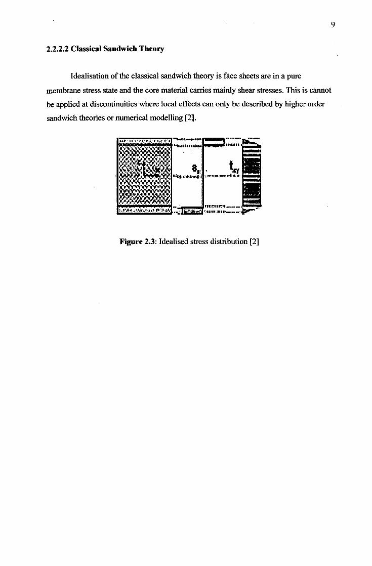
2.2.2.2 Classical Sandwich Theory
Idealisation of the classical sandwich theory is face sheets are in a pure
membrane stress state and the core material carries mainly shear stresses. This is cannot
be applied at discontinuities where local effects can only be described by higher order
sandwich theories or numerical modelling 121.
Figure 2.3: Idealised stress distribution [2]

2.3 General Formula of Shear Test Rig
General formula which relate to this project:
Shear: I P
A
N2 ni
For double faces of shear force:
Shear: I P
2A
- N
2 2
rri
Where;
I = Shear A = Area, F Force
10
11
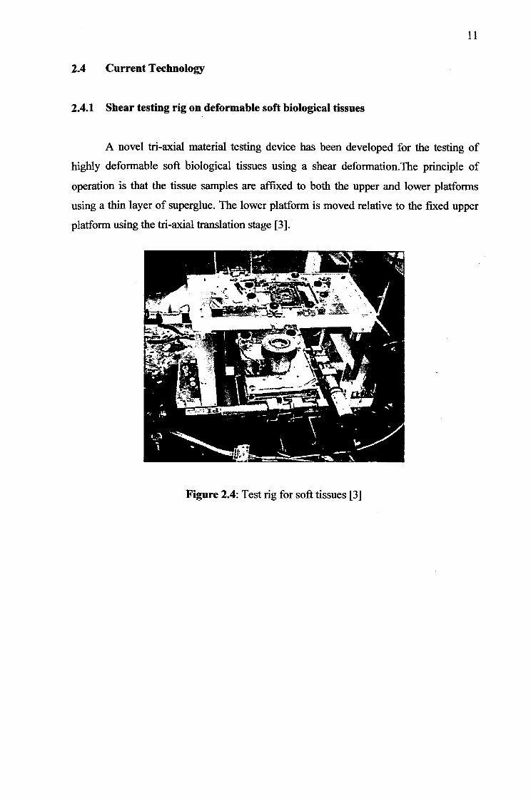
2.4 Current Technology
2.4.1 Shear testing rig on deforniable soft biological tissues
A novel tn-axial material testing device has been developed for the testing of
highly deformable soft biological tissues using a shear deformation.The principle of
operation is that the tissue samples are affixed to both the upper and lower platforms
using a thin layer of superglue. The lower platform is moved relative to the fixed upper
platform using the fri-axial translation stage [3].
Figure 2.4: Test rig for soft tissues [3]
12
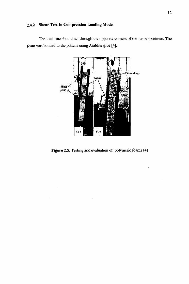
2.4.2 Shear Test In Compression Loading Mode
The load line should act through the opposite corners of the foam specimen. The
foam was bonded to the platens using Araldite glue [4].
Figure 2.5: Testing and evaluation of polymeric foams [4]
13
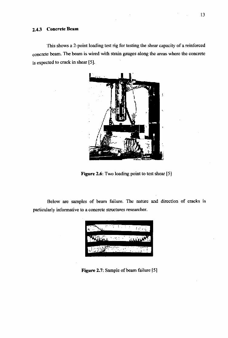
2.4.3 Concrete Beam
This shows a 2-point loading test rig for testing the shear capacity of a reinforced
concrete beam. The beam is wired with strain gauges along the areas where the concrete
is expected to crack in shear [5].
Figure 2.6: Two loading point to test shear [5]
Below are samples of beam failure. The nature and direction of cracks is
particularly informative to a concrete structures researcher.
Figure 2.7: Sample of beam failure [5]
14
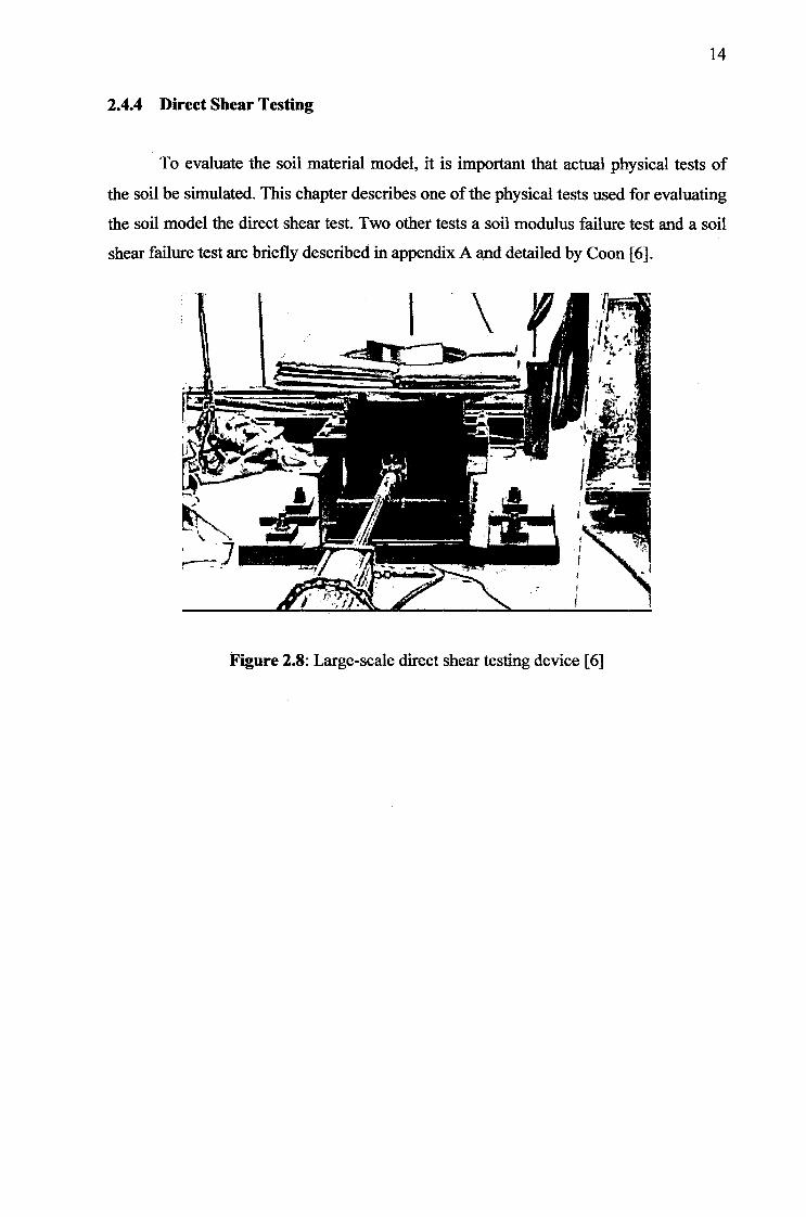
2.4.4 Direct Shear Testing
To evaluate the soil material model, it is important that actual physical tests of
the soil be simulated. This chapter describes one of the physical tests used for evaluating
the soil model the direct shear test. Two other tests a soil modulus failure test and a soil
shear failure test are briefly described in appendix A and detailed by Coon [6].
Figure 2.8: Large-scale direct shear testing device [6]
15
2.5 Milling Machine
2.5.1 Introduction
Milling machines are very versatile. They are usually used to machine flat
surfaces. They can also be used to drill, bore, cut gears, and produce slots. The type of
milling machine most commonly found in student shops is a vertical spindle machine
with a swivelling head. Although there are several other types of milling machines, this
document will focus only on the vertical milling machine. A milling machine removes
metal by rotating a multi-toothed cutter that is fed into the moving workpiece. The
spindle can be fed up and down with a quill feed lever on the head. The bed can also by
fed in the x, y, and z axes manually. In this clip the z axis is adjusted first, then the y,
than the x. Once an axis is located at a desired position and will no longer be fed, it
should be locked into position with the gibb locks. Most milling machines are equipped
with power feed for one or more axes. Power feed is smoother than manual feed and,
therefore, can produce a better surface finish. Power feed also reduces operator fatigue
on long cuts. On some machines, the power feed is controlled by a forward reverse lever
and a speed control knob [7].
2.5.2 Types of Milling Machine
Most of the milling machines are constructed of column and knee structure and
they are classified into two main types namely Vertical Milling Machine and Horizontal
Milling Machine. The name Vertical or Horizontal is given to the machine by virtue of
its spindle axis. Horizontal machines can be further classified into Plain Horizontal and
Universal Milling Machine. The main difference between the two is that the table of a
Universal Milling Machine can be set at an angle for helical milling while the table of a
Plain Horizontal Milling Machine is not [7].