Embed Size (px)
Citation preview

284 | P a g e
DESIGN AND FABRICATION OF SUN AND
PLANITORY GEAR FOR EPICYCLIC GEAR BOX BY
USING ADHESIVE MANUFACTURING
Mr V.Shyamu1, Mr P.Srinivas
2, Mr Ch.Jeevan
3, Dr.Alapati Venkateswarlu
4
1,2,3,4Guru Nanak Institutions Technical Campous, Hyderabad (India)
ABSTRACT
Planetary gearbox is widely used in industrial machineries and machine tools to obtain speed reduction, which
in turn increases the torque. These gearboxes are used in many applications such as power transmission system
and hybrid transmission systems. Planetary gear trains are one of the main subdivisions of the simple planetary
gear train arrangement. The Planetary gear train arrangement in general has a central “sun” gear which
meshes with and is surrounded by planet gears. The outer most gear, the ring gear, meshes with each of the
planet gears. The planet gears are held to a cage or carrier that fixes the planets in orbit relative to each other.
Planetary gear is a widely used industrial product in mid-level precision industry, such as printing lathe,
automation assembly, semi-conductor equipment and automation system. Planetary gearing could increase
torque and reduce load inertia while minimized the speed. To compare with conventional gearbox, planetary
gear box has several advantages. One advantage is its unique combination of both compact arrangement and
outstanding power transmission efficiencies. A typical efficiency loss in a planetary gearbox arrangement is
only 3% per stage. This type of efficiency ensures that a high proportion of the energy being input is transmitted
through the gearbox, rather than being wasted on mechanical losses inside the gearbox. Another advantage of
the planetary gearbox arrangement is load distribution.
Keywords: Sun and Planetary gear train, 3D Printing, lithography
I. INTRODUCTION
Transmission refers to the transfer of engine torque to another system whenever required. A reduction unit used
for this purpose is the “gear box‟‟.Gear box is a device placed in between the clutch and the rest of the
transmission. It is devices that changes the speed and torque and transmit power from the engine to the driving
wheel. Gear boxes are generally classified as a) Selective type b) Progressive type c) Epicyclical or Planetary
type.
From this above classifications we have projected on Epicyclic or Planetary Gear box. This is also known as
Planetary Gear Train. One shaft is called sun gear shaft and the other shaft is called planet carrier shaft.
The arrangement of the gears and the relative movements are shown in the fig.1.1

285 | P a g e
Fig 1.1 Arrangement of Planetary gear train
The central gear is known as sun gear which is in constant mesh with two or three gears called planet gears. The
sun gear will rotate only on its own axis. But the planet gears, apart from rotating about their own axes, also
revolve around the sun gear. The planet gear is also in constant mesh with the internal tooth of the ring gear
provided. The ring gear is sometimes called as annulus.
II. LITERATURE REWIEV
The technology for printing physical 3D objects from digital data was first developed by Charles Hull in 1984.
He named the technique as Stereo lithography and obtained a patent for the technique in 1986.While Stereo
lithography systems had become popular by the end of 1980s, other similar technologies such as Fused
Deposition Modeling (FDM) and Selective Laser Sintering (SLS) were introduced.In 1993, Massachusetts
Institute of Technology (MIT) patented another technology, named "3 Dimensional Printing techniques", which
is similar to the inkjet technology used in 2D Printers. Speeds, extremely low costs, and within a broad range of
applications. This paper describes the core technology and its related applications. Z-Corp first introduced high-
resolution 3D Printing (HD3DP™) in 2005. The HD3DP concept is the result of a combination of print-head
technology, advancement, firmware, and mechanical design. Z Corp.‟s highly engineered inkjet print heads,
with 600-dpi, high-resolution capabilities, are the product of years of research.In 1996, three major products,
"Genisys" from Stratasys, "Actua 2100" from 3DSystems and "Z402" from Z Corporation, were introduced.
Originally developed at the Massachusetts Institute of Technology (MIT) in 1993, Three-Dimensional Printing
technology (3D) forms the basis of Z Corporation‟s prototyping process.3DP technology creates 3D physical
prototypes by solidifying layers of deposited powder using a liquid binder. By definition 3DP is an extremely
versatile and rapid process accommodating geometry of varying complexity in hundreds of different
applications, and supporting many types of materials. Z Corp. pioneered the commercial use of 3DP technology,
developing 3D printers that leading manufacturers use to produce early concept models and product prototypes.
Utilizing 3DP technology, Z Corp. has developed 3D printers that operate at unprecedented.
III.THEORY OF 3D PRINTING
3D printing is a form of additive manufacturing technology where a three dimensional object is created by
laying down successive layers of material. It is also known as rapid prototyping, is a mechanized method
whereby 3D objects are quickly made on a reasonably sized machine connected to a computer containing

286 | P a g e
blueprints for the object. The 3D printing concept of custom manufacturing is exciting to nearly everyone. This
revolutionary method for creating 3D models with the use of inkjet technology saves time and cost by
eliminating the need to design; print and glue together separate model parts. Now, you can create a complete
model in a single process using 3D printing. The basic principles include materials cartridges, flexibility of
output, and translation of code into a visible pattern.
3D Printers are machines that produce physical 3D models from digital data by printing layer by layer. It can
make physical models of objects either designed with a CAD program or scanned with a 3D Scanner. It is used
in a variety of industries including jewelry, footwear, industrial design, architecture, engineering and
construction, automotive, aerospace, dental and medical industries, education and consumer products
3D printing technology leverages 3D source data, which often takes the form of computer-aided design (CAD)
models. Mechanical CAD software packages, the first applications to create 3D data, have quickly become the
standard for nearly all product development processes. Other industries such as architectural design
have also embraced 3D technologies because of the overwhelming advantages they provide, including improved
visualization, greater automation, and more cost-effective reuse of 3D data for a variety of critically important
applications.
3.1 3d Printing Technology
Current 3D Printing Technologies:
Stereo lithography: - Stereo lithographic 3D printers (known as SLAs or stereo lithography apparatus) position
a perforated platform just below the surface of at of liquid photo curable polymer. A UV laser beam then traces
the first slice of an object on the surface of this liquid, causing a very thin layer of photopolymer to harden. The
perforated platform is then lowered very slightly and another slice is traced out and hardened by the laser.
Another slice is then created, and then another, until a complete object has been printed and can be removed
from the vat of photopolymer, drained of excess liquid, and cured.
Fused deposition modeling:-Here a hot thermoplastic is extruded from a temperature-controlled print head to
produce fairly robust objects to a high degree of accuracy.
Selective laser sintering (SLS):- This builds objects by using a laser to selectively fuse together successive
layers of a cocktail of powdered wax, ceramic, metal, nylon or one of a range of other materials.
Multi-jet modeling (MJM):- This again builds up objects from successive layers of powder, with an inkjet-like
print head used to spray on a binder solution that glues only the required granules together.
The Flash printer:- manufactured by Canon, is low-cost 3D printer. It‟s known to build layers with a light-
curable film. Unlike other printers, the V Flash builds its parts from the top down.
Inkjet 3D printing:-It creates the model one layer at a time by spreading a layer of powder (plaster, or resins)
and inkjet printing binder in the cross-section of the part. It is the most widely used 3-D Printing technology
these days and the reasons beyond that are stated below.
IV. OBJECTIVES
The intend of the paper is to achieve the following
1. For the gearing ratio benefits and to get more accurate 3D prints
2. This innovative technology has been proven to save companies time, man power and money.
287 | P a g e
3. Companies providing 3D printing solutions have brought to life an efficient and competent technological
product.
4. Design and fabricate various types of sun and planetary Gears for specific Gear Boxes.
V. RESEARCH METHODOLOGY
Planetary gearbox is commonly used to obtain speed reduction and increasing torque in winch mechanism.
Which is a mechanical device powered by planetary gear reduction system for hauling or pulling. Planet carrier
is basic but most important part of mechanical winch. It provides support to the planet gear, bearings and the
gear loadings. The strength of the Planet carrier is an important parameter to be taken into account while
designing. In order to evaluate the strength, of the Planet carrier, a step by step approach is adopted.
To solve this problem it is essential to carry out the analysis of Planet carrier and redesign the existing Planet
carrier in order to improve strength as well as save material. Gears are present in all kinds of machinery and
vehicles because of their advantages over other available methods of transmitting power and matching the
speeds and torques of one machine to another. Gear transmissions usually exhibit high power-to-weight ratios,
can be made very compact and present the major advantage of high efficiency.
VI. GENERAL PRINCIPLE OF 3D PRINTING
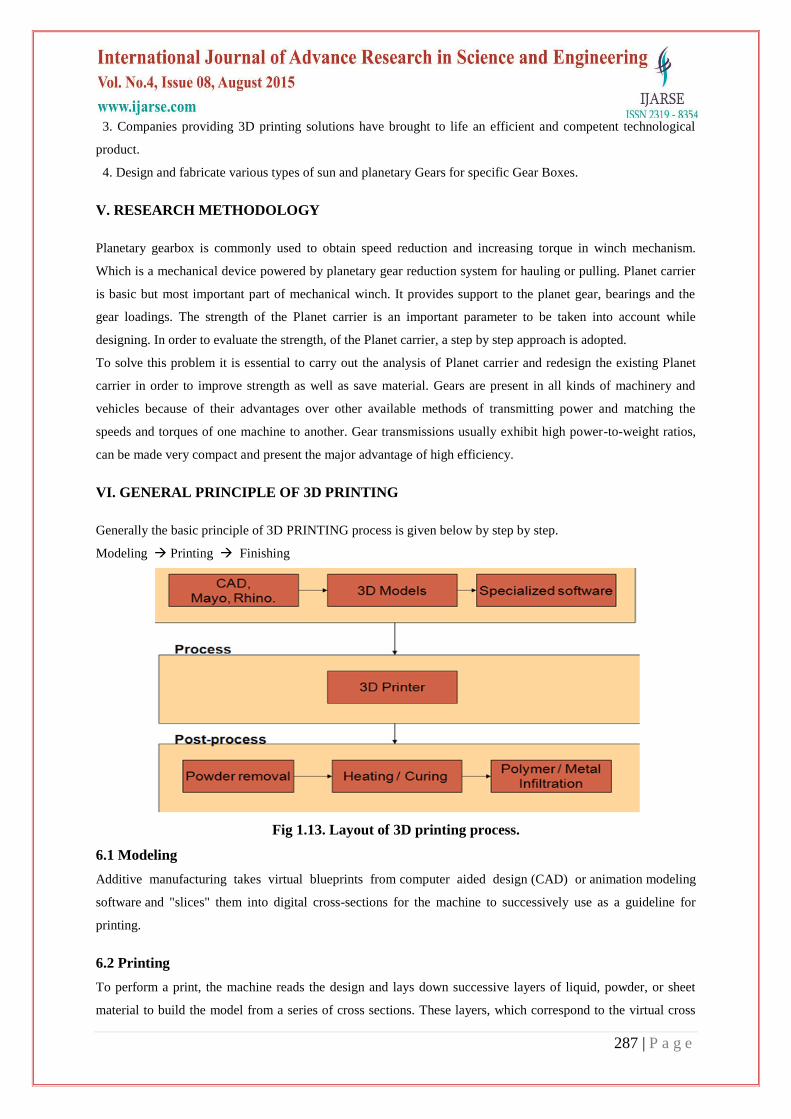
Generally the basic principle of 3D PRINTING process is given below by step by step.
Modeling Printing Finishing
Fig 1.13. Layout of 3D printing process.
6.1 Modeling
Additive manufacturing takes virtual blueprints from computer aided design (CAD) or animation modeling
software and "slices" them into digital cross-sections for the machine to successively use as a guideline for
printing.
6.2 Printing
To perform a print, the machine reads the design and lays down successive layers of liquid, powder, or sheet
material to build the model from a series of cross sections. These layers, which correspond to the virtual cross

288 | P a g e
sections from the CAD model, are joined together or automatically fused to create the final shape. The primary
advantage of this technique is its ability to create almost any shape or geometric feature.
Fig 1.14. General principle of 3D printing
6.3 Finishing
Though the printer-produced resolution is sufficient for many applications, printing a slightly oversized version
of the desired object in standard resolution, and then removing material with a higher-resolution subtractive
process can achieve a higher-resolution.
6.4 Accuracy
3D printing produces parts additively, layer by layer, using materials that are processed from one form to
another to create the printed part. This processing may introduce variables, such as material shrinkage, that must
be compensated for during the print process to ensure final part accuracy. Powder-based 3D printers using
binders typically have the least shrink distortion attributable to the print process and are generally highly
accurate. Plastic 3D printing technologies typically use heat and/or UV light as energy sources to process the
print mate.
3D printing technology is limited to specific material types. Materials are typically grouped as plastic,
composite, wax, metal, ceramic, and other non-plastic. Your selection of a 3D printer should be based on which
material categories provide the best combination of value and application rangerials, adding additional variables
that can impact accuracy.
VII. RESULT AND MODELING
7.1 Design Calculation of Sun And Planetary Gear
7.1.1 Design Calculation
𝑵𝟐
𝑵𝟏 =
𝑻𝟏
𝑻𝟐
𝑵𝟐
𝑵𝟏 ×
𝑵𝟑
𝑵𝟐 =
𝑻𝟏
𝑻𝟐 ×
𝑻𝟐
𝑻𝟑 =
𝑻𝟏
𝑻𝟑

289 | P a g e
Table: Technical Specification of Gearbox
Parameters Sun gear Planet gear Ring gear
Number of Teeth (N) 17 19 55
Pitch circle Diameter
(DPC)
153 171 495
Root Diameter(DR) 135 153 517.5
Modular (m) 9 9 9
Pressure angle 20 20 20
Pressure angle 20 20 20
Table : Tabular method for sun and planetary gear.
Operation
Revolution of
Arm A Sun gear S Planet gear P Annular gear
I
1. Arm A fixed,
+1 revolutions
to S, cw
2. Multiply by x
3. Add y
0
0
y
+1
+x
x+y
-T1/T2
-T1/T2 *x
Y
-T1/T3
-T1/T3*x
ys
Mt = 106×60 (𝑘𝑤 )
2 ∏𝑛1
Where, n1 = 1000 rpm
Mt = 22736.4 × 103 N-mm
Mt = Torque transmitted by gear (N-mm)
PW = power transmitted by gear ( kw )
n1 = speed of rotation (rpm)
22736.4 × 103 =
106×60 ×30
2 ∏𝑛1
n1 = 106×60 ×30
2 ∏×22736 .4×1000

290 | P a g e
n1 = 50.42 rpm
tangential load Pt = 2𝑀𝑡
𝑑 =
2×22736 .4×1000
153
Pt = 297207.84 N
Pr = Pt tanα
Pr = 297207.84 × tan(20) = 108174.5 N
Mb = Pr × h
h = Addendum + Dedendum
= 1.15m + 1m
= 1.15 × 9 + 1× 9
h = 19.35 mm
Mb = Pr × h
= 108174.5 × 19.35
Mb = 2093.18 KN-mm
I = bt3 /12
b = 10 mm, t = 2∏×67.5
2×17
t = 12.47 mm
I = 10×12.473
12
y = 𝑡2
6ℎ𝑚 =
12.472
6 ×19.35 ×9
y = 0.15
σb = 𝑃𝑡 × ℎ ×
𝑡
21
12 × 𝑏 𝑡3
σb = 22.190 KN
Theoretical tangential load, Pt = b σb [ 𝑡2
6ℎ ]
= 10 × 22190.199 [ 12.472
6×19.35 ]
Pt = 297.208 KN
Actual tangential load, Pt = mbσby
= 9×10×22190.109×0.15
Pt = 299.567 KN
7.2 Modeling
The planetary single stage consists of Housing, planet carrier with four planets, a sum and a planet-ring wheel.
The planet-ring is non-rotating and can be considered as rigid multi-body with discrete flexibilities of full
gearbox with free boundaries. Technical parameters for the planetary gearbox. We are designing the sun and
Planetary gear by using Pro-E Software.

291 | P a g e
7.2.1 Importance of Pro-E Software
This self-paced tutorial is modeled on portions of the book titled "Inside Pro ENGINEER" by James Utz and W.
Robert Cox (Onward Press). Typical time required to complete the tutorial is 1-2 hours. READ the instructions
CAREFULLY during the exercise, especially the part about saving your work. Pro/ENGINEER is a feature
based, parametric solid modeling program. As such, its use is significantly different from conventional drafting
programs. In conventional drafting (either manual or computer assisted), various views of a part are created in
an attempt to describe the geometry. Each view incorporates aspects of various features (surfaces, cuts, radii,
holes, protrusions) but the features are not individually defined. In feature based modeling, each feature is
individually described then integrated into the part.
The other significant aspect of conventional drafting is that the part geometry is defined by the drawing. If it is
desired to change the size, shape, or location of a feature, the physical lines on the drawing must be changed (in
each affected view) then associated dimensions are updated. When using parametric modelling, the features are
driven by the dimensions (parameters). To modify the diameter of a hole, the hole diameter parameter value is
changed. This automatically modifies the feature wherever it occurs - drawing views, assemblies, etc. Another
unique attribute of Pro-ENGINEER is that it is a solid modelling.
The model to be manufactured is built up a layer the design procedure is to create a model, view it, and
assemble parts as required, then generate any drawings which are required. It should be noted that for many uses
of Pro/E, complete drawings are never created. A typical design cycle for a melded plastic part might consist of
the creation of a solid model, export of an SLA file to a rapid prototyping system (stereo lithography, etc.), use
of the SLA part in hands-on verification of fit, form, and function and then export of an IGES file to the molder
or tool.
Planet gear mechanism can transform rotary motion into reciprocating linear motion with high efficiency, high
accuracy, stability, and reliability. Its application in combine harvester cutter can improve cutting performance
significantly and reduce harvest losses of the cutting process. This paper builds the parametric 3D model of the
planet gear mechanism for realizing automatism modelling of variable basic parameters with Creo software.
Using virtual prototype technology, this paper imports the model into ADAMS software and implements
kinematic simulation analysis, getting the characteristic curve of key moving components displacement,
velocity, and acceleration. The results can provide effective parameters and helps for design of the planet gear
mechanism and its application on the combine harvester cutter at a time.
7.2.2 Manufacturing A Model With 3d Printer
A layer of powder is automatically deposited in the model tray. The print head then applies resin in the shape of
the model. The layer dries solid almost immediately. The model tray then moves down the distance of a layer
and another layer of power is deposited in position, in the model tray. The print head again applies resin in the
shape of the model, binding it to the first layer. This sequence occurs one layer at a time until the model is
complete.

292 | P a g e
Fig: 3D printing process
7.2.3 How 3d Printing Works
3D printers work like inkjet printers. Instead of ink, 3D printers deposit the desired material in successive layers
to create a physical object from a digital life.
Fig: 3D printing works

293 | P a g e
1) A laser source sends a laser beam to solidify the material.
2) The elevator raises and lowers the platform to help lay the layers.
3) The vat contains the material used to create the 3D object.
4) The 3D object is created as parts are layered on top of each other.
5) Advanced 3D printers use one or more materials, including plastic, resin, titanium, polymers and even gold
and silver.
7.2.4 Conventions for 3D PRINTER Operations
TEN MEANU ITEMS ON THE Pc displays are shown in this shorthand convention:
MENU1>[MENU2>]ACTION
Where[MENU2>]is one or more optional items .
For example, PREPARE>PREHEAT means:
1.Make sure you‟re on the watch screen (the default screen when the printer is turned on):
220/2200 220/2220
0
02h 58m b118/1200
070% .
SDHouse9co021%
2. Press the dial when in watch screen to get the main menu shown below:
Watch
Prepare
Control
Card Menu
3. Rotate the dial to highlight prepare as above ,and press the dial again to select it.
Main
Preheat
Move axis
Cool down
4. It opens the prepare menu shown above .now rotate the dial to highlight Preheat ,and click to select it. The
complete the instruction sequence.
The action item typically causes an activity in machine, but won‟t always reflect immediately on the display.
7.2.5 Coding
G codes
The 3D PRINTER (and most CNC machines for that matter) understands “g codes”

294 | P a g e
G codes are basically Plain text files which specify progressive positions of all axes of the CNC machine.
Coupled a with the so-called “M CODES”, a CNC machine can be carefully controlled. G codes normally
follow standard protocols across machines, but M codes are machine dependent.
It is the responsibility of external programs to convert the design to the manufactured into g codes. You can get
a feel of g codes by studying a file generated by Slic3r (read on).The supported codes for the PROTOCENTER
999 are here:
7.2.6 HOMING
The printer automatically locates the absolute coordinates via a process called “HOMING”.
Basically, when it is instructed to home ,it starts towards the negative direction of the X,Y&Z axes.At the
minimum point it hits an optical end –stop,which marks the lowest coordinate of the axis in question. For Z, it
is 0.FOR X& Y ,it is –( X Size/2) & -(Y SIZE/2)mm (-115,-115)
Note: Proto Centre 999 always homes Y before it home X. This is specific to its mechanical design, and is done
to keep the overall things simple.
7.2.7 Get a 3D design
Any *stl design. Download , designed
7.3 Stl File Programme
7.3.1 Repair and reorient it if needed
A design must be “watertight” the surface defining the design should have no gaps in it, and there must be no
zero-thickness features in the design .If needed, the free basic edition of NETFABB for can be used to repair a
design for 3D printing.
Slice it
Install suitable slicing software on your PC.
7.3.2 CURA
Install cura for your operating system from the supplied SD CARD.
After installation ,cura will prompt you to add a new machine .Click next.
When selecting a machine choose “other”.

295 | P a g e
7.3.3 Save to SD card
Pop in a micro SD card into your computer ,copy the g- code file onto it, safely remove the card and insert the
card into the printer.
VIII. CONCLUSION
1) We have prepared the 3D model of sun and planetary gear in pro-e software and compute the programme
in 3D printer of STL file finally made the prototype by using 3D printing technology.
2) 3D printing helps companies save upto 70% of their manufacturing cost.
3) The speed of 3D printing is quicker as compared to the traditional method.
4) Less wastage of material.
Fig: 3D Print of sun and planetary gear
REFERENCES
[1]. „Theory of machines‟ R.S.Khurmi and J.K.Gupta, S.Chand Publications,2002
[2]. http://www.efunda.com/designstandards/gears/gears_epicyclic.cfm
[3]. http://www.How stuffworks.com
[4]. http://www.wikipedia.com
[5]. „Introduction to mechanisms‟ yi zhang with susan finger and Stephannie Behrens
[6]. http://www.technologystudent.com/gears1/worm1.htm
[7]. http://gemini.tntech.edu/~slc3675/me361/lecture/geartrn.html
[8]. http://www.engr.utexas.edu/dteach/teacherpdi/2007materialsNXT/Gear Notes.pdf
[9]. http://www.ticona.com/home/tech/design/gears.htm.
[10]. Text book of Elements of mechanical engineering by S.Trymabaka Murthy
[11]. Design of machine elements by V B Bhandari