Embed Size (px)
Citation preview

DESIGN AND FABRICATION OF A SEMI AUTOMATIC GEAR SHIFTING
MECHANISM FOR UTeM FORMULA STYLE RACE CAR
AMMAR ALFAIZ BIN MUSTAFFA ALBAKRI
UNIVERSITI TEKNIKAL MALAYSIA MELAKA

‘I/We have read this thesis
and from my/our* opinion this thesis
is sufficient in aspects of scope and quality for awarding
Bachelor of Mechanical Engineering (Automotive)’
Signature :……….………………………………
Name of Supervisor I :……………………………………….
Date :……………………………………….
Line which is irrelevant

DESIGN AND FABRICATION OF A SEMI AUTOMATIC GEAR SHIFTING
MECHANISM FOR UTeM FORMULA STYLE RACE CAR
AMMAR ALFAIZ BIN MUSTAFFA ALBAKRI
Laporan ini dikemukakan sebagai memenuhi sebahagiaan daripada syarat
penganugerahan Ijazah Sarjana Muda Kejuruteraan Mekanikal (Automotif)
Fakulti Kejuruteraan Mekanikal
Universiti Teknikal Malaysia Melaka
MAC 2011
DECLARATION
“I hereby declare that the work in this report is my own except for summaries and quotations which have been duly acknowledged.”
Signature :….………………………………
Author :…………………………………..
Date :…….…………………………….

“To All Student, Learn By Heart”

ACKNOWLEDGEMENT
I would like to express my gratitude to all those who gave the possibility to
complete this project. I want to thank Mr.Muhd Ridzuan Mansor for giving me
permission to commence this project in the first instance, to do the necessary research
work and modeling project. I would like to thank to technician Mr. Nasir and who gave
and confirmed workshop permission and encouraged us to go ahead with project. I’m
deeply indebted with my friends whose help, stimulating suggestions and
encouragement helped me in all the time of research for and writing of this project
especially Amar Ridzuan, Mat, Birin, Ula, Atok, Faliq and Kamal. I want to thank them
for all their help, support, interest and valuable hints.
Finally, I would like to give my special thanks to parent, Mr. Mustaffa Albakri
and Mrs. Aminah, and my siblings whose patient love enabled me to complete this work.
.
Thank you.
30nd March 2011

iv
ABSTRACT
This project is about design and fabrication a semi – automatic gear shifting
mechanism for a Formula Varsity race car based on the rules and specification. This
gear shift mechanism system had been design to resolve shifting gear problem,
eliminate fully mechanical gear shift and to have a better cockpit area. This design
was referred to the many motorcycle shift mechanism patent as a benchmark and
than had been modified to implement at the race car. All the concept design had been
perform with computer aided drawing (CAD) software – CATIA to have a better
physical view. After the drawing completed, material application was selected and
perform some basic analysis. Then after performing the analysis, all the design will
be transfer to the detail marking on the belong material to be fabricate. All the
components must be fabricated according to detail design and after finished
fabrication, all the component are installed and tested to evaluate system
functionality. Test showed that the system can be operate normally (shift up or
down) in a certain time. But for the maximum usage condition, an external power
source must be attached to the system.
v
ABSTRAK
Projek ini adalah mengenai merekabentuk and memfabrikasi separuh
automatic mekanisma penukar gear bagi jentera lumba Formula Varsity 2010
berdasarkan peraturan dan speksikasi. Mekanisma ini telah direka bagi bagi
mengatasi penukaran gear, mengurangkan penggunaan penukar gear penuh
mekanikal dan untuk mendapatkan ruang pemanduan yang lebih besar. Kebanyakkan
rekabentuk ini bedasarkan rekabentuk mekanisma penukaran gear untuk motorsikal
sebagai asas rekaan dan telah di modifikasi untuk penggunaan jentera lumba.
Kesemua konsep rekabentuk menggunakan lukisan terbantu komputer – CATIA utuk
memperolehi bentuk fizikal yang baik. Selepas rekabentuk selesai, pemilihan bahan
dan analisis setiap komponen telah dilakukan. dan kesemua rekabentuk komponen
telah diterjemahkan kepada pengukuran perincian pada bahan projek untuk
difabrikasikan. Setiap komponen telah difabrikasi mengikut perincian rekabentuk.
Selepas selesainya proses fabrikasi, semua komponen telah dipasang pada kenderaan
dan telah diuji kefungsiannya. Ujian yang menunjukkan sistem berfungsi dengan
sempurna tetapi untuk kegunaan yang extrim, sistem memerlukan janaan kusa
daripada luar.

vi
CONTENTS
CHAPTER ITEMS PAGE
DECLARATION
DEDICATION
ACKNOWLEGDEMENT
i
ii
iii
ABSTRACT iv
ABSTRAK v
CONTENTS vi
LIST OF TABLES x
LIST OF FIGURES xi
LIST OF SYMBOLS xii
CHAPTER 1 INTRODUCTION
1.0 Gear shifter background 1
1.1 Scope 4
1.2 Problem Statement 5
CHAPTER 2 LITERATURE REVIEW
2.0 Introduction 6
2.1 Current design 7
2.2 Formula one transmission technology 9
2.3 Motorcycle transmission shifting mechanism 10
2.4 Passenger car transmission 16
2.5 Gear shifter mechanism 20
2.6 Design with computer aided drawing 23

vii
2.7 Material selection
2
CHAPTER 3 METHODOLOGY
3.0 Introduction 27
3.1 Problem identify 28
3.2 Concept design and generate 29
3.3 Design selection 30
3.4 Material Selection 31
3.5 Load analysis 33
CHAPTER 4 DESIGN SELECTION
4.0 Introduction 34
4.1 Product specification design 35
4.2 Solution generation 37
4.3 Conceptual design 38
4.4 Concept one 40
4.5 Concept two 43
4.6 Concept three 46
4.7 Electronic controller 48
4.8 Design selection 49
4.9 Detail design 52
4.10 Material Selection 53
CHAPTER 5 MECHANICAL COMPONENT ANALYSIS
5.0 Introduction
56
5.1 Define shear stress on the gear lever
5.2 Define bending moment on gear lever
63
63
5.3 Define stress on the plunger 64
5.4 Define shear stress on the lock pin 65
5.5 Specified gear lever torque 65
5.6 Analysis by finite element 66
5.7 Factor of safety of each component 67

viii
CHAPTER 6 MANUFACTURING, ASSEMBLE AND
TESTING
PROCESS
6.0 Introduction
6.1 Marking and detailing process
6.2 Machining process
6.3 Welding process
6.4 Wiring and soldering
6.5 Assemble and fitting process
6.6 Testing process
6.7 Material preparation
6.8 Component fabrication
6.8.1 Solenoid fabrication
6.8.2 Solenoid mounting fabrication
6.8.3 Solenoid plunger fabrication
6.8.4 Solenoid bush and cover fabrication
6.8.5 Gear Lever fabrication
6.8.6 Shift pedal fabrication
6.8.7 Relay integration
6.9 Assemble and testing
6.9.1 Assemble and fitting
6.9.2 Testing and evaluation
69
71
72
73
74
75
75
76
78
78
78
79
80
81
82
83
83
83
85
CHAPTER 7
CONCLUSION AND RECOMMENDATION
7.0 Conclusion
7.1 Recommendation
7.1.2 Vary the solenoid (shifting mechanism)
force due to application
7.1.2 Improve current supply to the system
7.1.3 Modification on electric control to be fully
automatic gear shifter system
87
88
88
90
92

ix
7.1.4 Modeling the FVtronic system into
mathematical model (Simulink Model)
7.1.5 New adaptive transmission in Formula
Varsity Race Car is major step forward in
semi – automatic transmission performance
i. Driver type recognition
ii. Environmental recognition
iii. Driving situation recognition
97
98
100
100
101
REFERENCES
BIBLIOGRAPHY
APPENDICES

x
LIST OF TABLES
NO. TITLE PAGE
1.1
2.1
4.1
4.2
4.3
4.4
4.5
6.1
6.2
Part of technical specification – transmission/gearbox
Cable actuated gear shifter test
Product design specification
Application of logic method to criteria of semi –auto gear shifter
Weighing factor for criteria of semi – automatic gear shifter
Concept rating
Material properties of Teflon, aluminum and mild steel
Material belong
The result of the gear shifter
4
8
36
49
50
51
55
76
86

x

xi
LIST OF FIGURES
NO. TITLE PAGE
1.1
2.1
2.2
2.3
2.4
2.5
2.6
2.7
2.8
3.1
3.2
3.3
3.4
4.1
4.2
4.3
4.4
4.5
4.6
4.7
4.8
4.9
4.10
4.11
Formula Varsity race car
Gear shifter in the cockpit – current design
Motorcycle transmission shifting mechanism assembly
Motorcycle shift pedal assembly
Motorcycle transmission shifter mechanism
Mechanical linkage gear shifter
Cable actuated gear shifter
Concept design by using CAD software
Plot using Ashby’s own CES selector software
Project planning main point
One of digital logic method presentation
Final design
Material selection criteria
FVTRONIC operation flow system
Cam and drum with servo operated
Explode drawing
Bell crank and linkage mechanism actuated by solenoid operated
Explode drawing
Pivot arm and push rod mechanism with solenoid actuated
Explode drawing
Electronic system flow
Chart of digital logic method to criteria of semi –automatic gear
Final design
Explode design
Von Mises Stress (Max) = 78.7MPa
5
8
10
11
12
22
22
24
26
29
32
32
34
37
42
42
44
45
51
47
47
49
50
52
52
xii
5.1
5.2
5.3
5.4
6.1
6.2
6.3
6.4
6.5
6.6
6.7
6.8
6.9
6.10
6.11
6.12
6.13
6.14
6.15
6.16
6.17
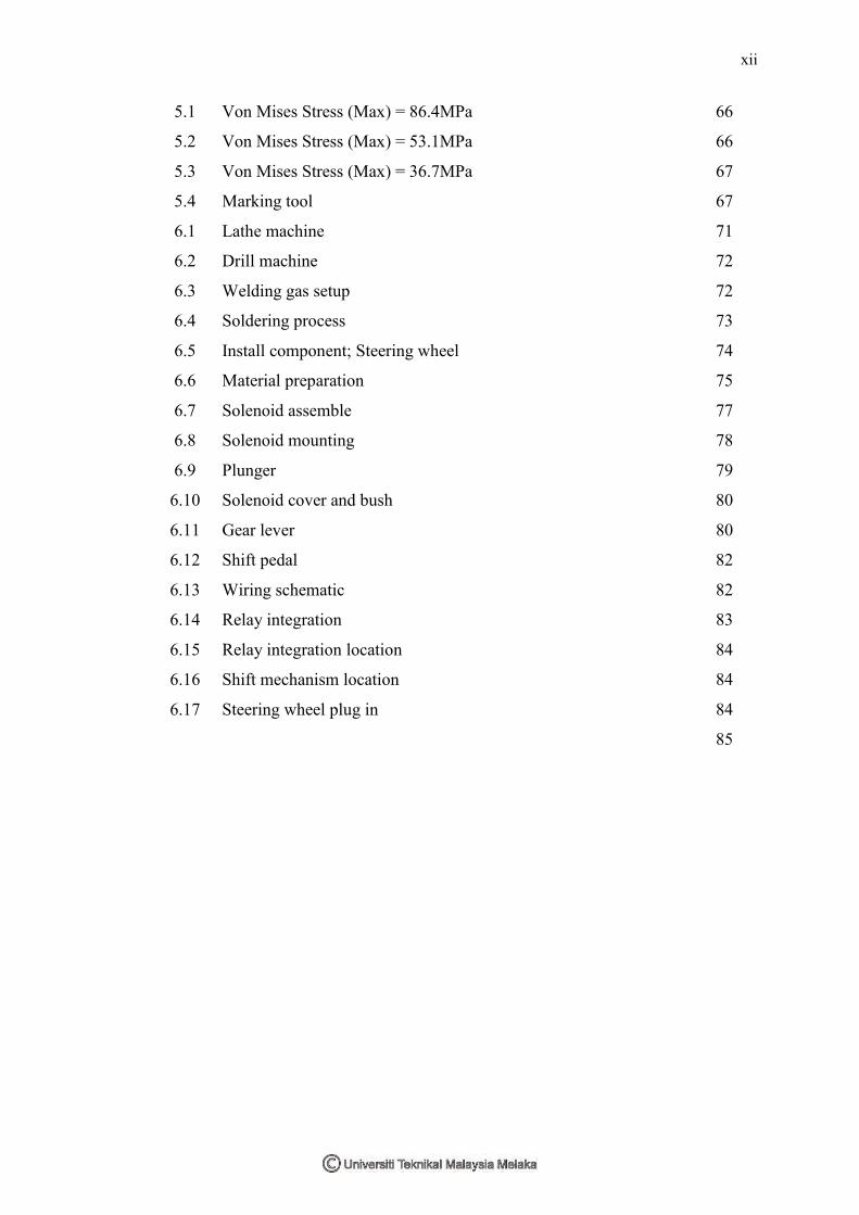
Von Mises Stress (Max) = 86.4MPa
Von Mises Stress (Max) = 53.1MPa
Von Mises Stress (Max) = 36.7MPa
Marking tool
Lathe machine
Drill machine
Welding gas setup
Soldering process
Install component; Steering wheel
Material preparation
Solenoid assemble
Solenoid mounting
Plunger
Solenoid cover and bush
Gear lever
Shift pedal
Wiring schematic
Relay integration
Relay integration location
Shift mechanism location
Steering wheel plug in
66
66
67
67
71
72
72
73
74
75
77
78
79
80
80
82
82
83
84
84
84
85

xiii
LIST OF SYMBOLS
R = outer radius of the shaft.
τ = maximum shear stress at the outer surface.
φ = angle of twist in radians.
T = torque (N·m or ft·lbf).
ℓ = length of the object the torque is being applied to or over.
G = shear modulus or more commonly the modulus of rigidity and
is usually given in giga pascals (GPa), lbf/in2 (psi), or lbf/ft2
J = torsion constant for the section
r = distance from the center of rotation
V = total shear force at the location in question
Q = statically moment of area
t = thickness in the material perpendicular to the shear
I = Moment of Inertia of the entire cross sectional area
τ = torque vector and τ is the magnitude of the torque,
F = force vector, and F is the magnitude of the force
θ = angle between the force vector and the lever arm vector.
1
CHAPTER 1
INTRODUCTION
1.0 Gear Shifter Background
A Shiftronic transmission can operate just as a conventional automatic
transmission, but it also allows the driver to override the automatic mode by moving
the shift lever into a second shift gate equipped with two spring-loaded positions: "up
shift" and "downshift". Once in this gate, the driver takes over most of the shifting
decisions ordinarily performed by the transmission's computer, permitting, for
example, the delaying of an up shift for increased acceleration or to increase the
braking effect of the engine (Crouse and Anglin 1993).
For a manual transmission, gear shift mechanism comprises a lever-receiving
structure disposed on the engine/transmission structure. The lever-receiving structure
includes a mechanical or with cable actuated. A manual transmission gear shift
mechanism has a plurality of shift rods, each of which is provided with a shift fork
and at least two of which are coaxially disposed, a control rod having at least two
select arms which selectively engage with the shift rods, and a shift lever for sliding
control rod so as to place the transmission into any one of a plurality of gears. The

2
select arms are disposed on the control rod either at specified axial separations along
an axis of rotation of the control rod or at specified angular separations around an
axis of rotation of the control rod. This is the same of the cable actuated gear shifter.
Besides automatics, there are also other types of automated transmissions such
as continuous variable transmissions (CVTs) and semi-automatic transmissions, that
free up the driver from having to shift gears manually by using the transmission's
computer to change gear, if for example the driver were redlining the engine. Despite
superficial similarity to other automated transmissions, automatic transmissions
differ significantly in internal operation and driver's "feel" from semi-automatics and
CVTs. An automatic uses a torque converter instead of clutch to manage the link
between the transmission and the engine, while a CVT uses a belt instead of a fixed
number of gears, and a semi-automatic retains the clutch like a manual but activates
the clutch through electrohydraulic means (http://en.wikipedia.org).
Formula One cars use semi-automatic sequential gearboxes, with regulations
stating a maximum of seven forward gears and one reverse gear, using rear wheel
drive. The gearbox is constructed of carbon fiber or titanium, and is bolted onto the
back of the engine. Full automatic gearboxes, and systems such as launch control and
traction control, are illegal, to keep driver skill important in controlling the car. The
driver initiates gear changes using paddles mounted on the back of the steering
wheel and electro-hydraulics perform the actual change as well as throttle
control. Clutch control is also performed electro-hydraulically, except to and from a
standstill, when the driver operates the clutch using a lever mounted on the back of
the steering wheel. As of the race season, all teams are using seamless shift
transmissions, which allow almost instantaneous changing of gears with minimum
loss of drive. Shift times for Formula One cars are in the region of 0.05 seconds
(Peter 2001).
UTeM Formula Varsity is a student racing competition that challenges
students to design, manufacture and race their single seat open-wheel formula style
racing car in real track condition. Therefore, there are a few systems to design for
example engine and transmission. Each the design and fabrication must be following

3
by the rules specification to ensure each team racing has the almost same race car
design and capability. One of the rules specifications is transmission and gearbox and
the most popular gear shifter for the formula varsity race car are cable actuated and
mechanical linkage. These two designs are the most common design and easily to
fabricated to the formula varsity race car. Simply, a lever mounted in cockpit with
attach to the cable or link arm it will actuated transmission shaft. A motorcycle
engine with capacity up to 135 cc will be use as the power generate to the race car.
This moped bike engine come completed with variable gear ratio or gear box and
need a gear shifter to engage and disengage the gear to transmit the torque to the tire
(http://www.f1technical.net).
For the further design, a new system call FVTRONIC is design to eliminate
fully mechanical gear shift and shifting the gear simply by pressing a shift button on
the steering wheel. This is because of the, the older design had a weakness such as
shifting delay and easily deformed after a few usage. This new system needed a
forces and motion to operate the transmission shaft that can be supplied by
electromagnet mechanism. This electromagnet mechanism has helped the size and
light weight. Much than that, this system will be offer a quick gear shift response and
maximize the cockpit size – eliminate gear lever.
4
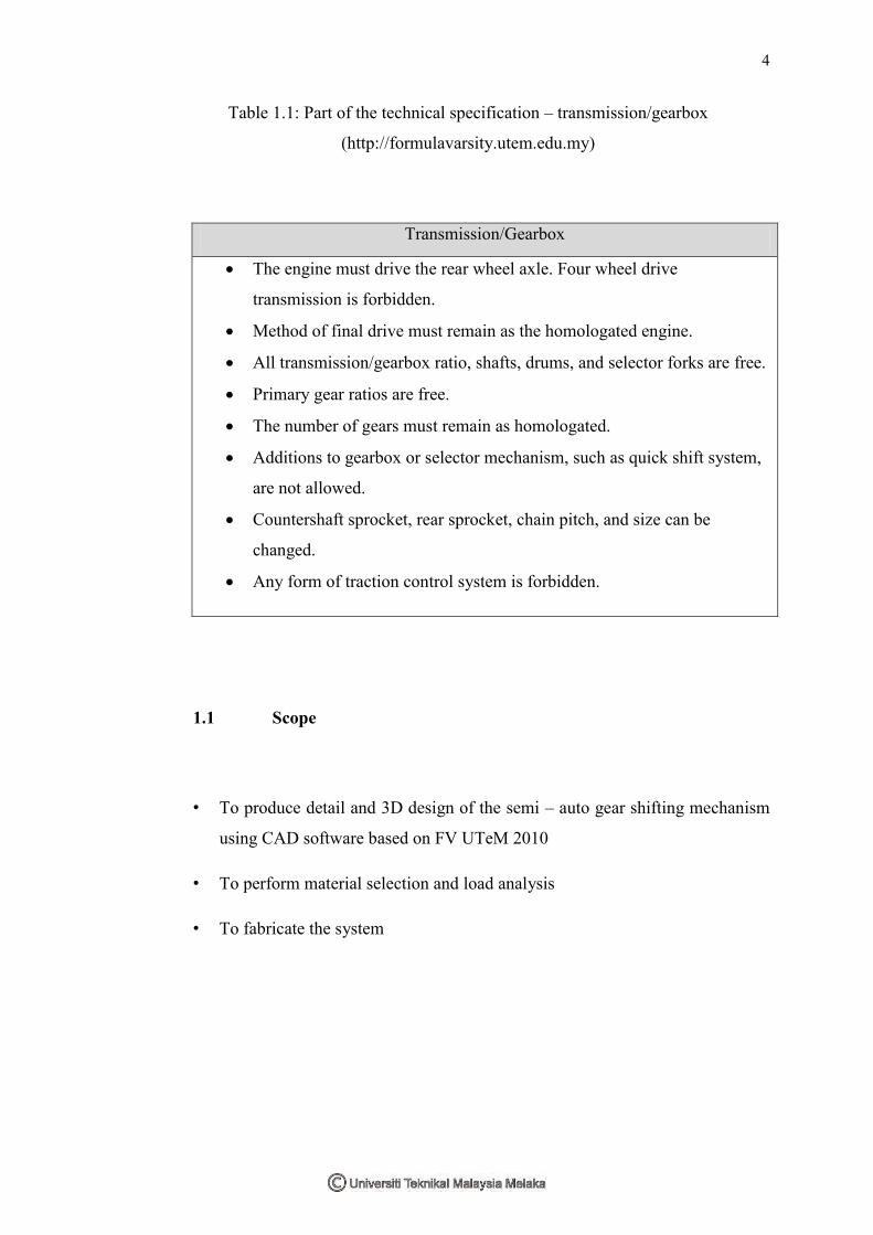
Table 1.1: Part of the technical specification – transmission/gearbox
(http://formulavarsity.utem.edu.my)
Transmission/Gearbox
The engine must drive the rear wheel axle. Four wheel drive
transmission is forbidden.
Method of final drive must remain as the homologated engine.
All transmission/gearbox ratio, shafts, drums, and selector forks are free.
Primary gear ratios are free.
The number of gears must remain as homologated.
Additions to gearbox or selector mechanism, such as quick shift system,
are not allowed.
Countershaft sprocket, rear sprocket, chain pitch, and size can be
changed.
Any form of traction control system is forbidden.
1.1 Scope
• To produce detail and 3D design of the semi – auto gear shifting mechanism
using CAD software based on FV UTeM 2010
• To perform material selection and load analysis
• To fabricate the system

5
1.3 Problem Investigation
This new invention started when a few problems comes out from the current
design. The most obvious problem is fully mechanical either cable actuated or
linkage gear shift can be deformed at the certain part and after that difficult to change
the gear after a few training session or race event. This is notice on the current race
car FV2010 model. The most critical part is the hinge and gear selector on the
transmission shaft. These two parts will be start deform and break at the welding
point because of the force acting on them especially variable driver’ hand force while
move the gear lever. Race car driver also notice that the current design are very delay
while engage or disengage and not quickly response. During the race, driver needs a
very quick response due to the gear shift because to maintain the engine torque and
speed during cornering or accelerating. This is the one important factor to ensure
driver win the race. Moreover, driver complains that ability to maneuver while
changing gear is very poor. During taking the ‘hair pin’ cornering, driver must be
concern on steering input and also have to maintain the speed. It is very difficult to
change gear while maneuver in a tiny cockpit. As mention on above, a formula
varsity race car must be single seated that mean very tiny cockpit. If a gear lever
mount in the cockpit, driver layout position become space less and not ergonomic. It
will disturb driver comfortable and focus when racing. For that, a new shift system
will encounter all the problems (http://american muscle cars: power to the people).
Figure 1.1 Formula Varsity race cars

6
CHAPTER 2
LITERATURE REVIEW
2.0 Introduction
A literature review is a body of text that aims to review the critical points of
current knowledge including substantive findings as well as theoretical and
methodological contributions to a particular topic. Literature reviews are secondary
sources, and as such, do not report any new or original experimental work.
Most often associated with academic-oriented literature, such as theses, a
literature review usually precedes a research proposal and results section. Its ultimate
goal is to bring the reader up to date with current literature on a topic and forms the
basis for another goal, such as future research that may be needed in the area. A well-
structured literature review is characterized by a logical flow of ideas; current and
relevant references with consistent, appropriate referencing style; proper use
of terminology; and an unbiased and comprehensive view of the previous research on
the topic.
7
In this case, most of the literature review will covers all the fact, design and
technical discussion and invention to be evaluated and idea generate for the concept
design. The main literature review will cover formula one transmission technology,
new invention on motorcycle invention and material selection method. Most of the
research done by reviews the journals, technical paper, books, patent and internet
source.
2.1 Current Design
The gear shift is the part of the gearbox which has the shift forks and allows
the contact from the driver to the synchronization. Most of the time they are so much
like the gear counter plus the reverse gear. And they make it possible to choose the
gear (gear ratio) and to switch this in or out. The invention of the gear shift is
attributed to Karl Benz. These are the parts for which it is possible to make
automation. Further these parts can be designed so compact so that it is also possible
to build a very modular transmission with less weight.
The benefit of the compact build of the shifting is not only the gain of
modulation and less weight but also the time during the production and space in the
whole drive train. Depending on the space around the whole drive train and type of
car, for automatisation a hydraulic, pneumatic or electric actuator can be used. For
personal cars, a hydraulic or electric actuator is most often used. Further, such a
system also needs an electronic application. (Harbans, 2005)
Based on the current Formula Varsity car gear shifter mechanism, most of the
design was cable actuated or fully mechanical linkage mechanism. Normally the gear
shifter will be located in the cockpit as the easy to driver to reach and to engage gear
ration. Therefore, this will cause a limited space in the cockpit. Much than that, this
cable actuated and mechanical linkage gear shifter easily has a failure at the certain
time for the racing use. A test had been done to both mechanism and shows the result


![Semi-Solid SIMA Processed 7075 Aluminum Alloy · 2018. 1. 20. · Semi-solid metal processing is a single step fabrication method for production of near net shape metallic parts [1–3]](https://img.pdfslide.net/doc/110x75/60bf92eedf4cda5c7c296663/semi-solid-sima-processed-7075-aluminum-alloy-2018-1-20-semi-solid-metal-processing.jpg)