Embed Size (px)
Citation preview
Design and Functional Validation of a Mechanism for Dual-Spinning CubeSats
Eric Peters, Pratik Davé, Ryan Kingsbury, Meghan Prinkey,
Anne Marinan, Evan Wise, Christopher Pong, Kerri Cahoy,
William Thalheimer, Devon Sklair, Luis Orrego
10 August 2013 This work is sponsored by the Assistant Secretary of Defense for Research & Engineering under Air Force Contact FA8721-05-C-0002. Opinions, interpretations, conclusions, and recommendations
are those of the authors and are not necessarily endorsed by the United States Government.

Outline
• Overview / Motivation
• Scanner assembly design
• Structural validation
– Physical models
– Structural testing of rotor/shaft interface
– Notes on tolerance rings
• Thermal validation
– Test plan
– Results from thermal testing
10 August 2013 2 SmallSat 2013 PCW

Motivation
10 August 2013 3 SmallSat 2013 PCW
• Dual-spinning CubeSats – Payload scans Earth cross-track for coverage
– Bus fixed in LVLH frame for pointing
• MicroMAS: Micro-sized Microwave Atmospheric Satellite – 3U dual-spinning CubeSat for remote
weather sensing
– 1U passive microwave radiometer payload, MIT Lincoln Laboratory
– 2U bus, MIT Space Systems Laboratory
– Scheduled to launch in winter 2013-14
– Talk on Thurs. Aug 15th @ 10:30am

Design Requirements
• Scanner assembly must:
– Fit in 10cm x 10cm x 3.5 cm volume
– Rotate 1U payload at ~1 Hz (60 rpm)
– Have angular position knowledge of < 6 arcmin (0.1 deg)
– Have 8+ electrical feed lines for power/data transfer between bus and payload
– Operate continuously in space environment
10 August 2013 SmallSat 2013 PCW 4
MAI-400 ADCS Unit
Payload
Avionics Stack
Bus
Scanner Assembly

COTS Hardware
Bearing • NHBB RI-3026 thin section
bearing with vacuum-rated cage and lubricant
Encoder • MicroE M1500V vacuum-rated
sensor • Glass rotary grating disc with
7200 counts per revolution (0.01 degrees per count)
Rotor/Stator • Aeroflex Z-0250-050-3-104
zero-cogging brushless DC motor
Slipring • Aeroflex CAY-1398 with 12 lines
for power/data transfer
10 August 2013 5 SmallSat 2013 PCW
Scanner Assembly Housing
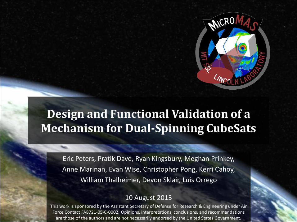
Design Overview
Stator
Housing
Chassis Cover Plate
Rotor
Encoder Disc
Encoder Disc Mounting Hub
Encoder Sensor
Slipring
Bearing
Base Plate
Blue: Rotary
Green: Stationary
Bold: Custom
10 August 2013
Shaft
Slipring Retainer
Bearing Retainer
Bearing Shim
6 SmallSat 2013 PCW

Structural Validation of Scanner Assembly
10 August 2013 7 SmallSat 2013 PCW

Scanner Assembly Prototypes
10 August 2013 SmallSat 2013 PCW 8
3D Print Unit • Check volume • Check fit • Verify assembly procedures
Engineering Design Unit
• Verify mass properties • Verify machining procedures • Early functional testing with non-
flight components
Rotor/Shaft Test Units
• Test/prove different mating methods work for interface
Engineering Test Unit
• Verify custom parts function, cost, schedule
• Functional test with flight-like components

Rotor/Shaft Interface
Epoxy Tolerance Ring Press-Fit
Advantages
• Flight heritage (ACIS instrument, bond held with ΔT of -200 °F)
• Robust to thermal expansion/contraction
• Known torque and radial load capacities
• No additional parts needed
• Simple to design
Disadvantages
• High CTE • Estimated elastic
modulus • Requires careful
application, curing
• No prior experience • No flight heritage • Tests needed to get
groove fit right
• Loss of fit with thermal variation
• Requires additional equipment
Tests Performed
Torque testing Torque testing Thermal testing
10 August 2013 SmallSat 2013 PCW 9
• Concern: thermal expansion, loss of contact between rotor (stainless steel) and rotor shaft (aluminum)
• Tested several mating methods

Rotor/Shaft Mating Tests
• Purpose: Test strength of rotor/shaft interface
• Use peak torque provided by motor (4 in-lb) on epoxy and tolerance ring
• Setup: Used identical flight-like shaft + rotor ring sets
Shaft • Aluminum alloy 6061-T6 • Cut grooves for epoxy • Found deeper groove
needed for tolerance ring Ring
• A513 mild steel • Smooth internal surface
0.390 in
0.005 in
1.546 in
0.550 in
10 August 2013 10 SmallSat 2013 PCW
Shaft + rotor ring test rig

Torque Testing Setup
• 1/2”-13 bolt secured through bore in center of test shaft
• Flat washers placed between shaft-nut and shaft-bolt
• Fastener installation torqued to 120 in-lb
• Ring held by vise while torque applied to the bolt
Grade 8, 1/2-13 bolt Lock washer
Lock washer Nut
10 August 2013 11 SmallSat 2013 PCW

Tolerance Ring Attempts
• First attempt, tolerance ring forced out of the groove
– Initial 0.005" groove depth too shallow
• Machined new shaft with groove depth of 0.022”
– Designed to fully retain the 0.020” un-corrugated portion and ¼ of the corrugated portion
• Trimmed length of ring to maintain gap of 0.060” between edges
– Gap of 0.040” - 0.080” recommended by product engineers
10 August 2013 12 SmallSat 2013 PCW
Image from: USA Tolerance Rings

Torque Testing Results
• First, test to peak torque provided by motor during nominal operations (4 in-lb)
– If successful, then test to point of failure
• Results:
– Both epoxy and tolerance rings survived up to 65 in-lb torque
– Point of failure was not reached for either epoxy or tolerance ring
• At 65 in-lb, lock washers used in test apparatus dug into aluminum shaft
• Test was halted and not continued to higher torques
• Note:
– Tolerance ring: tested to less than max torque capacity of rings (65 in-lb test << 675 in-lb predicted capacity)
– Epoxy: tested to much less than epoxy shear strength at ~25°C (tested 44 psi << rated 3800 psi)
10 August 2013 SmallSat 2013 PCW 13
Thermal Validation of Scanner Assembly
10 August 2013 14 SmallSat 2013 PCW

Thermal Testing
• Purpose: Characterize encoder + motor assembly performance over operational/survival temperatures in vacuum
10 August 2013 SmallSat 2013 PCW 15
• Analog output from encoder Oscilloscope
• Digital output from encoder to motor controller PC
• Temperature data w/ 9 x 100-Ω RTDs Agilent DAQ

Thermal Test Plan
Scenario Chamber State Test Procedure
TS Test Setup Room Pressure
& Temperature
• Prep chamber, test rigs, articles, + sensors • Check function + calibrate test articles + sensors • Collect benchmark data
T-0 Functional Checks
Ambient Vacuum ( 25 °C )
• Pump-down chamber to ~1e-05 torr • Functional checks on test articles + sensors • Command motor to 60 rpm • Collect data until thermally stable
T-1 Cold Test Cold Vacuum
( < 0 °C )
• Continue running motor at 60 rpm • Continue collecting data • Supply LN2 to bring encoder temperature to 0°C • Monitor encoder, slowly lower T to -10 °C
T-2 Thermal Cycling
Cold Vacuum ( 0 °C )
Hot Vacuum ( 70 °C )
• Command motor to 60 rpm, collect data • Complete 1+ full thermal cycles by switching
between LN2 cooling and resistor heating
10 August 2013 SmallSat 2013 PCW 16
Encoder specified operational temperature range = [0,70] °C
Predicted on-orbit temperature range = [-5,25] °C

Encoder Performance
680
700
720
740
760
780
800
-10 0 10 20 30 40 50 60 70
Enco
de
r Si
gnal
Vo
ltag
e (
mV
)
Encoder Temperature (degC)
Ch. A (mV)
Ch. B (mV)
Avg Voltage (mV)
10 August 2013 17 SmallSat 2013 PCW
Encoder V still in nominal range (> 400 mV) despite drop at higher temps
Nominal = 800 mV, minimum acceptable = 400 mV

Scanner Performance
7100
7120
7140
7160
7180
7200
7220
7240
7260
7280
7300
-10 0 10 20 30 40 50 60 70
Enco
de
r Si
gnal
Fre
qu
en
cy (
Hz)
Encoder Temperature (degC)
Nominal signal frequency = 7200 Hz
10 August 2013 18 SmallSat 2013 PCW
Encoder signal frequency stable over temp stable scanner performance

MicroMAS Scanner Summary
• Validated scanner assembly: design achieves requirements
• Successful iterative design process – Prototypes and physical models for structural and
thermal testing
• Successful tests on two rotor/shaft mating methods – (1) Epoxy + grooves – (2) Tolerance rings – Both methods passed torque tests of up to 65 in-lb – Selected Epoxy + grooves
• Successful test of encoder/scanner performance with temperature at vacuum pressure
• Future work: Thermal test epoxy/tolerance ring
10 August 2013 SmallSat 2013 PCW 19

Backup Slides
10 August 2013 20 SmallSat 2013 PCW

Temperature Data
0 2000 4000 6000 8000 10000 12000 14000 16000 18000-10
0
10
20
30
40
50
60
70
Time since Pump-down (sec)
Tem
perature (degC
)
Test Day 1 - Cold Test
Thermal Plate (E)
Encoder (N)
Bottom Plate (NE)
Side Wall (NW)
Chassis Plate (SE)
Bracket (N)
Bracket (W)
Bracket (E)
Mounting Plate (SW)0 2000 4000 6000 8000 10000 12000 14000 16000 18000
-10
0
10
20
30
40
50
60
70
Time since Pump-down (sec)
Tem
pera
ture
(d
egC
)
Test Day 1 - Cold Test
Thermal Plate (E)
Encoder (N)
Bottom Plate (NE)
Side Wall (NW)
Chassis Plate (SE)
Bracket (N)
Bracket (W)
Bracket (E)
Mounting Plate (SW)
0 0.5 1 1.5 2 2.5
x 104
-10
0
10
20
30
40
50
60
70
Time since Pump-down (sec)
Tem
perature (degC
)
Test Day 2 - Full Cold/Hot Cycle
Thermal Plate (E)
Encoder (N)
Bottom Plate (NE)
Side Wall (NW)
Chassis Plate (SE)
Bracket (N)
Bracket (W)
Bracket (E)
Mounting Plate (SW)
0 2000 4000 6000 8000 10000 12000 14000 16000 18000-10
0
10
20
30
40
50
60
70
Time since Pump-down (sec)
Tem
pera
ture
(d
egC
)
Test Day 1 - Cold Test
Thermal Plate (E)
Encoder (N)
Bottom Plate (NE)
Side Wall (NW)
Chassis Plate (SE)
Bracket (N)
Bracket (W)
Bracket (E)
Mounting Plate (SW)
70
60
50
40
30
20
10
0
-10
Tem
pera
ture
(°C
)
Time since pump-down (1000 seconds) Time since pump-down (1000 seconds)
Test 1: Cold Test Test articles cooled to -8.5 °C, then returned to ambient
Test 2: Thermal Cycling Test articles cooled to 0 °C, then heated to 65 °C
0 2 4 6 8 10 12 14 16 18 0 5 10 15 20 25
10 August 2013
Motor and encoder operated nominally throughout all tested temperature ranges
Motor commanded to continuously spin at 60 rpm during entirety of both tests
21 SmallSat 2013 PCW

Encoder Signal at -5 °C
Active
computation of
signal amplitude
(voltage)
Active
computation of
signal
frequency
Encoder signal amplitude and frequency are both well within nominal range
10 August 2013
Signal is filtered and averaged by oscilloscope, as will be similarly done by on-board avionics
Nominal signal amplitude: > 400 mV Nominal signal frequency: 7.200 kHz
22 SmallSat 2013 PCW

Encoder Signal at +60 °C
Active
computation of
signal amplitude
(voltage)
Active
computation of
signal
frequency
Though the encoder signal amplitude decreased at higher temperature,
the signal amplitude and frequency are both still within nominal range
10 August 2013
Signal is filtered and averaged by oscilloscope, as will be similarly done by on-board avionics
Nominal signal amplitude: > 400 mV Nominal signal frequency: 7.200 kHz
23 SmallSat 2013 PCW