Embed Size (px)
Citation preview
P.I.: Cory KreutzerJohn Rugh, Task Leader
National Renewable Energy Laboratory
June 8, 2016
Project ID: VS165
This presentation does not contain any proprietary, confidential, or otherwise restricted information.
2016 VTO Annual Merit Review and Peer Evaluation Meeting
NREL is a national laboratory of the U.S. Department of Energy, Office of Energy Efficiency and Renewable Energy, operated by the Alliance for Sustainable Energy, LLC.
Design and Implementation of a Thermal Load Reduction System in a Hyundai PHEV

2
Overview
• Project start date: FY15• Project end date: FY17• Percent complete: 40%
• Risk Aversion: Manufacturers are reluctant to invest in and introduce new technologies
• Cost: Effective, timely evaluation of advanced vehicular components and configurations is needed.
• Range Anxiety: Large climate control loads can contribute significantly to electric drive vehicle (EDV) range anxiety
Fully Funded FOA Project• Total project funding: $3,054,817
o DOE share: $ 2,443,790o Contractor share*: $ 611,027
• Funding received in FY14: $ 2,443,790• Funding for FY16: $ 0
* Contractor share represents 20% cost share for the project
Timeline
Budget
Barriers
• Interactions/collaborations:o Hyundai America Technical Center, Inc. (HATCI)o Hanon Systemso Sekisui Chemical Company, Ltd.o Pittsburgh Glass Works, LLC.o PPG Industries, Inc.o Gentherm, Inc.o 3M Company
• Project lead: o National Renewable Energy Laboratory
Partners

3
RelevanceTHE CHALLENGE
• Increased adoption of EDVs requires overcomingo Original equipment manufacturer (OEM)
averse to risk of adopting technologieso Limited vehicle range and associated
customer range anxietyo Elevated cost of EDVs in comparison to
existing conventional vehicles
• Climate control loads significantly degrade EDV range
• Annual light-duty vehicle fuel use estimated at equivalent of 3 billion barrels of oil1
1. Data Source: EIA Annual Outlook 2015. http://www.eia.gov/forecasts/aeo/pdf/0383(2015).pdf, pg. A-17, accessed March 20162. Data Source: Argonne National Laboratory’s Advanced Powertrain Research Facility
2

4
RelevanceTHE OPPORTUNITY Alignment with DOE VTP
• Reducing climate control loads enableso Smaller, cheaper batterieso Smaller climate control componentso Advanced climate control strategies
• Load reduction system demonstration decreases OEM risk for adoption
• HVAC load reduction and advanced climate control design can positively impact occupant comfort
• Supports EERE 2016 – 2020 strategic plan o Develop technologies that enable the cost-
effective production of EVs and reduce vehicle energy use1
• Supports meeting EV Everywhere Grand Challenge targetso Efficient climate control technologies
1. Office of Energy Efficiency and Renewable Energy 2016-2020 Strategic Plan and Implementing Framework. http://energy.gov/sites/prod/files/2015/12/f27/EERE_Strategic_Plan_12.16.15.pdfHVAC: heating, ventilating, and air conditioning

5
Relevance
Increase grid-connected EDV range by 20% during operation of the climate control system over the standard vehicle configuration by reducing vehicle thermal loads• Design and implement the thermal load reduction system on a production
drivable vehicle• Test the range impact over the combined city/highway drive cycle at peak
heating and cooling conditions• Maintain occupant thermal comfort in implemented system
THE GOAL

6
AOP Milestones 2016FY 2015 FY 2016 FY 2017
Tech. Development & Specification
Modeling and Analysis
Technology Evaluation Testing
Project Phase I
Project Phase II
Vehicle Integration
Operational Testing & Validation
M1 M3
M2
M1: Instrument vehicle and complete winter test planM2: Complete CoolCalc cabin model & validate to dataM3: Complete winter technology evaluationM4: Complete summer technology evaluation (FY15 M3)
M4

7
Approach – Technology Areas
Solar Control GlassHeated Windshield
Cabin Insulation
Individual Door Glass Defrost/Defogger
Solar Reflective Paint
Heated Surfaces Around Driver
Climate Control Seating
Grid-connected Preconditioning

8
Approach – Two-Phase Process
Design and Development
Testing Analysis
Integration and Validation
Testing Analysis
Glazings
Paint
Zonal HVAC
Insulation
Seating
Individual Technologies
Down-Selected Technologies
Validated Models
Full SystemImpact on Range
National Results& Occupant Comfort
Individual Technology
Performance
TechnologyGo/No-Go
Phase I
Phase II

S%
XNN('6G0%h%5+7<13%61:%X16=)7L7%J-(6-+3)%V)*6#3+ N#",9*.*+
V).#B#.?+3%!(/")-3-E0%U<>M%G-+.%
U<>M%J0$*(6%%m+$(3#)(%C('5-'6+)/(%
;6<'16=%9+R+=%2613+%@7<M6<'1%
PIX&%50+(M6=%J)7-+M%d':+=L13%
I+0LG=+%&6?L1%50+(M6=%9'6:%d':+=L13%
QGG,N61-%&'MO'(-%d':+=L13%
I6=L:6<'1%H6-6%
I6=L:6<'1%H6-6%
I6=L:6<'1%H6-6%
=D@%a?33%J0$*(6%%<("#/3(%C('5-'6+)/(%

10
Approach – Range Estimation Process
Light-Duty Range Estimation ProcessThermal
Vehicle Cabin Climate Control
HVAC System Performance
Power Conversion
Performance
Vehicle Performance
Range
Mechanical Electrical
Tools Used For Process
Electrical
CoolCalc
Evaporator
Compressor
Condenser
Expansion Valve
Liquid
Vapor
Liquid + Vapor
Vapor
WarmAir
ColdAir
Fan
Receiver/Dryer
Liquid water
CoolingAir
CoolSim FASTSim

11
Accomplishments: Phase I Winter Baseline TestingStrong correlation between vehicles at varying environmental conditions
Transient Warm-Up Steady-State Heating
Mode Panel & Floor
Temperature Maximum
Blower Maximum
Recirculation Full / On
HVAC SettingsMode Auto
Temperature 72
Blower Auto
Recirculation Auto
HVAC Settings
Combined Heater Core and Positive Temperature Coefficient (PTC) Heater Energy Into Cabin
Combined Heater Core and PTC Heater Energy Into Cabin
12
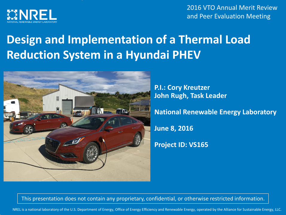
Accomplishments: Phase I Winter Technology EvaluationsInsulation: 10.6% penalty in warm-up and 9.6% improvement in steady-state
Baseline Door Panel Increased Insulation Door PanelAreas with Increased
Insulation
Headliner
Door Panels
Flooring
Package Tray
Pillars (where possible)
10.6% Increase9.6% Decrease
Combined Heater Core and PTC Heater Energy into Cabin
• Results are six day average
• Experimental method could be over estimating the warm-up penalty of insulation (investigating)
• Considerations for Phase II go/no-go include preconditioning, trip duration, soak time

13
Accomplishments: Phase I Winter Technology EvaluationsHeated Surfaces: 2% penalty in warm-up and 29-59% improvement in steady-state heating
Test Vehicle: Heated Surfaces
Driver: Door arm rest and bolster, crash pad, console wall, console top, advanced heated seatPassenger: Console wall, glove box, door arm rest and bolster
Test Method Highlights
Warm-Up: Energy until occupant sensation = 2Steady-State: Auto temp. adjusted in modified vehicle until occupant at target sensation
Select Heated Surfaces
29% Decrease56% Decrease
59% Decrease
Occupant A Occupant B Occupant C
Test results for Colorado winter environmentTransient Warm-Up: 2% Penalty Steady-State Heating: 29-59% Improvement

14
Accomplishments: CoolCalc Cabin ModelingSonata model developed and validated to experimental data to within 3.6%
CoolCalc – Rapid HVAC load estimation tool• A CoolCalc model of 2016 Hyundai Sonata was created• Model was validated with summer outdoor
experimental results • Model and experimental results agree to within an
average of 3.6% for cabin mean air temperature
Cabin Mean Air Temperature Comparison Door External Surface Temperature Comparison

15
Accomplishments – HVAC and detailed cabin modelingVehicle specific HVAC model developed and detailed cabin model in-progress
Detailed Cabin and Comfort/Sensation Modeling HVAC System Modeling
• Occupant and detailed vehicle thermal analysis tool development is in progress
• Interior volume computer-aided design is being refined/patched for mesh generation and TAITherm model
• A/C system model developed including control algorithm for preset evaporator capacity
• Model will be validated to experimental data collected by Hanon Systems

16
Accomplishments – National Level AnalysisDown-selection process completed for locations based on vehicle registrations• A process was developed to down-select typical meteorological year
(TMY3) locations based on light-duty vehicle registrations1
• Purpose of the processo Reduce the number of simulations for national-level analysiso Capture the most important weather environments across the countryo Generate registration-based weighting factors for each location simulated
839 Weather Stations 204 Weather Stations
1 2 3 4 5 6Millions of light-duty vehicle registrations per weather station
1. Vehicle Registration Data Source: 2014 Polk Vehicle Registration Database, https://www.ihs.com/btp/polk.html

17
Responses to FY15 AMR Reviewer Comments
Comment: The reviewer stated that quantifiable results from actual test will be very valuable. Should consider hot weather testing in a desert environment rather than at NREL.
Response: For Phase I of the project, both warm weather and cold weather testing of individual technologies will be completed at NREL. Testing during this phase of the project is aimed at maximizing repeatability and evaluating multiple technologies over the duration of a season. However, Phase II testing will be led by HATCI and will include more extreme environmental conditions similar to what was suggested.
Comment: …It is not clear whether advanced HVAC systems are being considered as part of this project….
Response: The project is focused on technologies that reduce the thermal demand of the existing on-board HVAC system of the vehicle and does not directly include advanced HVAC systems as part of the scope. However, some of the technologies evaluated are intended to provide a more direct method of conditioning the occupant, which could be considered as part of an advanced HVAC system. Finally, these technologies could enable reduced HVAC system capacities and alternative systems that are not currently able to meet capacity/performance requirements.
FY15 AMR Question 4: Proposed future research-the degree to which the project has effectively planned its future work in a logical manner by incorporating appropriate decision points, considering barriers to the realization of the proposed technology, and, when sensible, mitigating risk by providing alternate development pathways.
FY15 AMR Question 1: Approach to performing the work – the degree to which technical barriers are addressed, the project is well-designed, feasible, and integrated with other efforts.

18
Collaboration and Coordination
Hyundai America Technical Center• Subtier Industry Partner• Automotive OEM Supplier• Lead on Phase II Technology Integration• Lead on Phase II Full System Experimental Evaluation• Technology Supplier (collaboration with Gentherm)
Pittsburgh Glass Works• Subtier Industry Partner• Glass Package Manufacturer• Advanced Glass Technology Supplier
Hanon Systems• Subtier Industry Partner• Baseline HVAC System Experimental Evaluation• HVAC System Modeling Support Sekisui
• Subtier Industry Partner• Advanced Solar Control Interlayer Supplier
PPG Industries• Subtier Industry Partner• Automotive Paint Supplier• Advanced Paint Technology Supplier
3M• Subtier Industry Partner – in kind• Advanced Solar Control Film Supplier• Advanced Insulation Technology Supplier
Gentherm• Subtier Industry Partner – in kind• Door Defrost/Defog Technology Supplier• Heated Surfaces Technology Supplier (collaboration)• Advanced Seating Technology Supplier (collaboration)

19
Proposed Future WorkPhase I: Technology Design and Development (FY16)• Complete summer technology evaluations• Validate HVAC system model to experimental data • Complete development of CAE & comfort/sensation model development
and run analyses• Complete national-level analysis components, including time-of-day usage,
drive duration, and drive cycle selection(s) • Perform Phase I technology evaluation Go/No-Go for Phase II
Phase II: Technology Integration and Validation (FY16–17)• Integrate thermal load reduction technologies into drivable vehicle system• Perform operational cold weather, hot weather, and environmental chamber
testing at Hyundai America Technical Center facilities• Refine models with individual technology experimental results and perform
national-level analysis• Final vehicle demonstration and project summary presentation to DOE

20
Summary• The project’s focus is to implement a thermal load reduction system into a GCEDV
production vehicle and quantify the impact on thermal comfort, fuel use, and EV range• Key industry partners enable production-ready and cost-effective technologies and
vehicle-level integration• Testing and modeling/analysis are used synergistically to quantify system performance
and national relevance
Accomplishments• Completed Phase I winter baseline testing with a strong correlation between vehicles
in varying environmental conditions• Characterized the cold weather performance of added insulation, obtaining a 10.6%
penalty in warm-up and 9.6% advantage in steady-state• Characterized the cold weather performance of heated surfaces, obtaining a 2%
penalty in warm-up and 48% improvement in steady-state heating• A Hyundai Sonata CoolCalc model was developed and validated to experimental data• A vehicle-specific HVAC model has been developed, and a detailed cabin/occupant
model is in development • A national-level range estimation process is in development, and the down-selection
process for weather locations based on vehicle registrations is complete

21
Acknowledgements and ContactsSpecial thanks to:• David Anderson and Lee Slezak
Vehicle Systems Program, Vehicle Technologies Office
For more information:Cory KreutzerNational Renewable Energy [email protected]

22
Photo Credits
• Slide 4: Gentherm• Slide 11: Cory Kreutzer, NREL• Slide 12: Cory Kreutzer, NREL• Slide 13: Daniel Beckas, Gentherm• Slide 14: Cory Kreutzer, NREL• Slide 21: Dennis Schroeder, NREL

Technical Back-up Slides

24
Winter Heating Test Procedure
Transient Heating Phase “Steady-State” Heating PhaseCold Soak
𝒕𝒕𝟎𝟎
𝒕𝒕𝟏𝟏𝟏𝟏
𝒕𝒕𝟐𝟐 𝒕𝒕𝟑𝟑
Baseline Vehicle: Energy from 𝑡𝑡0 → 𝑡𝑡1𝑏𝑏
Modified Vehicle: Energy from 𝑡𝑡0 → 𝑡𝑡1𝑚𝑚
Both Vehicles:Energy from 𝑡𝑡2 → 𝑡𝑡3
MAX Heating Auto Heating (closed-loop) Vehicle OFF
• Heating test method used for baseline and insulation performance testing
𝒕𝒕𝟏𝟏𝟏𝟏
Baseline Vehicle
Modified Vehicle
Aver
age
Inte
rior A
ir Te
mpe
ratu
re

25
Heated Surfaces Test ProcedureTransient Heating
Phase“Steady-State” Heating PhaseCold Soak
𝒕𝒕𝟎𝟎 𝒕𝒕𝟏𝟏𝟏𝟏
MAX Heating Auto Heating (closed-loop) Vehicle OFF
𝒕𝒕𝟏𝟏𝟏𝟏
Control VehicleTest Vehicle
Auto 72
Occupant Adjust Auto Setpoint
25°C
Driv
er M
ean
Air T
empe
ratu
re
Control OccupantTest OccupantO
ccup
ant B
ody
Sens
atio
n
Neutral
+ 2.5
Control VehicleTest VehicleTo
tal T
herm
al
Pow
er
𝒕𝒕𝟐𝟐 𝒕𝒕𝟑𝟑

26
Phase I Summer A/C Test Approach
• Two-part A/C test method o Pull-down and steady-state phases independently measured
• Energy use during each test period integrated over specified time interval• Method is intended to increase repeatability and isolate technology impact
A/C Pull-Down A/C “Steady-State” PhaseSoak
𝒕𝒕𝟎𝟎
𝒕𝒕𝟏𝟏,𝟏𝟏𝒃𝒃𝒃𝒃𝒃𝒃𝒃𝒃𝒃𝒃𝒃𝒃𝒃𝒃 𝒕𝒕𝟐𝟐 𝒕𝒕𝟑𝟑
MAX A/C Auto A/C (closed-loop) Vehicle OFF
Aver
age
Inte
rior A
ir Te
mpe
ratu
re
time
Sunr
ise
𝒕𝒕𝟏𝟏,𝟏𝟏𝒎𝒎𝒎𝒎𝒃𝒃𝒎𝒎𝒃𝒃𝒃𝒃𝒎𝒎
Baseline ConfigurationModified Configuration