Embed Size (px)
Citation preview

Georgia Southern University
Digital Commons@Georgia Southern
Electronic Theses and Dissertations Graduate Studies, Jack N. Averitt College of
Spring 2017
Design and Modeling for DC Nanogrids Ormond D. Castle
Follow this and additional works at: https://digitalcommons.georgiasouthern.edu/etd
Part of the Electrical and Computer Engineering Commons
Recommended Citation Castle, Ormond D., "Design and Modeling for DC Nanogrids" (2017). Electronic Theses and Dissertations. 1603. https://digitalcommons.georgiasouthern.edu/etd/1603
This thesis (open access) is brought to you for free and open access by the Graduate Studies, Jack N. Averitt College of at Digital Commons@Georgia Southern. It has been accepted for inclusion in Electronic Theses and Dissertations by an authorized administrator of Digital Commons@Georgia Southern. For more information, please contact [email protected].

DESIGN AND MODELING FOR DC NANO-GRIDS
by
ORMOND D. CASTLE
(Under the Direction of Adel El Shahat)
ABSTRACT
Smart grids were constructed as a means of communication to the electric grid through
computer and other information technologies. This line of communication acts as gauge for
a more accurate reading of power consumed. A nano grid is a model version of a smart grid
with the ability to function as separate power generator. Such feature allows for this grid to
power single loads and apply for special applications. A DC-DC converter was designed to
apply to a nano grid which is a form of a smart grid. The converter was a single-input-multi-
output converter which is taking one DC voltage and applying it to two DC output voltages.
This boost converter takes the inputs and increases its voltages, leading to the outputs
respectively. The nano grid utilizes this proposed converter to carry out its special
characteristics. Procedures carried out in this research showed the success of the converter.
Further steps include the designing of a ring and radial architecture nanogrid to form a
microgrid. A comparison of results are made showing the efficiency and reliability of ring
architecture layout microgrids. Doing this creates a more complex system, and provides relief
to multiple sources to prevent outages.
INDEX WORDS: DC-DC Converter, Nanogrid, Microgrid

DESIGN AND MODELING FOR DC NANO-GRIDS
by
ORMOND D. CASTLE
B.S., Tuskegee University, 2015
A Thesis Submitted to the Graduate Faculty of Georgia Southern University in
Partial Fulfillment of the Requirements for the Degree
MASTER OF SCIENCE
STATESBORO, GEORGIA

© 2017
ORMOND CASTLE
All Rights Reserved

1
DESIGN AND MODELING FOR DC NANO-GRIDS
by
ORMOND D. CASTLE
Major Professor: Adel El Shahat
Committee: Rami Haddad
Mohammad Ahad
Electronic Version Approved:
May 2017

2
DEDICATION
To my beloved fiancé, mother, sister, and brother

3
ACKNOWLEDGEMENTS
First of all, I would like to thank to the almighty creator for flourishing my life with the most
lovable persons I could have ever imagined. I gratefully acknowledge the contribution of my
supervisor, Dr. Adel El Shahat, Assistant Professor of the Electrical Engineering Department of
Georgia Southern University, for providing me with the opportunity to work at the Power
Research Lab. His relentless efforts, motivation, guidance and influence put high impacts in this
project. I would also like to thank Dr. Brian Vlcek for providing me the absolute directions and
approach to write this thesis paper.
Lastly, I thank my fiance and family, without their persistent support, I would not be anywhere.

4
TABLE OF CONTENTS
LIST OF FIGURES……………………………………………………………………………….6
LIST OF TABLES………………………………………………………………………………...7
ABBREVIATIONS……………………………………………………………………………….8
1. CHAPTER 1: INTRODUCTION……………………………………………………………..9
1.1. The Growth of Smart Grids………………………………………………………………9
1.2. Interconnection of Smart Grids…………………………………………………….…...10
1.3. Breakdown if Thesis…………………………………………………………………….11
2. CHAPTER 2: LITERATURE REVIEW…………………………………………………….12
2.1. Smart Grids……………………………………………………………………………...12
2.2. Micro Grids……………………………………………………………………………...13
2.3. Nano Grids………………………………………………………………………………14
2.4. DC-DC Converter……………………………………………………………………….16
2.5. Single Input Single Output Converter (SISO)…………………………………………..17
2.6. Single Input Multiple Output Converter (SIMO)……………………………………….18
2.7. Multiple Input Single Output Converter (MISO)……………………………………….19
2.8. Multiple Input Multiple Output Converter (MIMO)……………………………………20
2.9. DC Protection Systems………………………………………………………………….21
2.9.1. Line Current Derivative………………………………………………………….21
2.9.2. Control Power Sequencing………………………………………………………22
2.9.3. Differential Protection Strategy………………………………………………….23
2.9.4. Coordination Strategies and Effective Protection Coordination System………...24
2.10. DC Distribution Systems………………………………………………………...25
2.10.1. Distribution: Design, Operation and Control…………………………………….25
2.10.2. Local Power Distribution for Micro-grids and Nano-grids……………………...26
2.11. DC Storage Systems……………………………………………………………..27
2.11.1. Decentralized Control for Smart Grids: Micro-grid and Nano-grid……………..27
2.11.2. Multilevel Energy Management System…………………………………………27
2.12. DC Architecture………………………………………………………………….28
2.12.1. Modeling and Power Flow for Micro-grid……………………………………….28
2.12.2. Distributed Energy Network for Nano-grids…………………………………….29
2.12.3. Radial Distribution……………………………………………………………….30
3. CHAPTER 3: DESIGN AND APPLICATIONS FOR NANO-GRID SYSTEMS………….31
3.1. Design of Single Input Multiple Output DC-DC Converter…………………………….31
3.1.1. System Configuration……………………………………………………………31
3.1.2. Circuit Equations………………………………………………………………...32
3.1.3. Modes of Operation……………………………………………………………...36
3.2. Ring Scheme Architecture and Decentralized Supply…………………………………..37
3.2.1. Architecture Background………………………………………………………...37
3.2.2. Optimal Power Flow Equations for Decentralized Architecture………………...38

5
4. CHAPTER 4: EXPERIMENT RESULTS AND FINDINGS……………………………….40
4.1. DC-DC Boost Converter………………………………………………………………...40
4.1.1. Boost Converter Design………………………………………………………….40
4.1.2. SIMO Converter and Nano-grid Applications…………………………………...41
4.1.3. Results from SIMO Converter…………………………………………………...42
4.2. Ring Architecture Layout……………………………………………………………….51
4.2.1. Results from Ring Layout………………………………………………………..53
4.3. Radial Architecture Layout……………………………………………………………...59
4.3.1. Results from Radial Layout……………………………………………………...60
5. CHAPTER 5: CONCLUSION AND RECOMMENDATIONS…………………………….63
5.1. Conclusion………………………………………………………………………………63
5.2. Recommendations for Future Work…………………………………………………….63
6. REFERENCES………………………………………………………………………………65

6
LIST OF FIGURES Page
Figure 1: Elements of a Smart Grid (Farhangi 2010)………………………………………..13
Figure 2: Schematic of Nano-grid (Nordman 2010)……………………………………........15
Figure 3: Single-Input-Single-Output Boost Converter……………………………………...17
Figure 4: Single-Input-Multi-Output Buck-Boost Converter………………………………..18
Figure 5: General Form of MISO Converter (Gummi and Ferdowsi 2012)…………………19
Figure 6: Multi-Input-Multi-Output Buck Boost Converter…………………………………21
Figure 7: Block Diagram of Proposed Topology…………………………………………….34
Figure 8: Basic Ring Architecture…………………………………………………………...38
Figure 9: Simulink Model of Proposed Converter……………………………………….......40
Figure 10: Pulses from the Generator……………………………………………………......42
Figure 11: Output Voltage of 13 Volts………………………………………………………43
Figure 12: Output Voltage of 21 Volts………………………………………………………44
Figure 13: Output Voltage of 93 Volts………………………………………………………45
Figure 14: SIMO Converter Current 1 - 137 milliamps……………………………………..46
Figure 15: SIMO Converter Current 2 – 95 milliamps ……………………………………...47
Figure 16: SIMO Converter Current 3 – 66 milliamps………………………………………48
Figure 17: Total Harmonic Distortion 1……………………………………………………..49
Figure 18: Total Harmonic Distortion 2……………………………………………………..50
Figure 19: Total Harmonic Distortion 3…………………………………………………......51
Figure 20: Ring Architecture Simulink Model…………………………………………........52
Figure 21: Primary Voltage – Ring………………………………………………………......53
Figure 22: Primary Current – Ring…………………………………………………………..54
Figure 23: Power from PV Panel – Ring………………………………………………….....55
Figure 24: Secondary Power Source…………………………………………………………56
Figure 25: Average Load Output – Ring…………………………………………………….57
Figure 26: Power from Battery – Ring………………………………………………………58
Figure 27: Radial Architecture Simulink Model…………………………………………….59
Figure 28: Primary Voltage – Radial…………………………………………………….......60
Figure 29: Primary Current – Radial………………………………………………………...61
Figure 30: Power from PV Panel – Radial……………………………………………….......62

7
LIST OF TABLES Page
Table 1: Devices for Micro-grid (Bui, Chen, et. al, 2014)……………………………………….25
Table 2: Required Components for SIMO Converter………………………..…………………..31

8
ABBREVIATIONS
Single Input-Single-Output DC-DC Converter (SISO)
Single-Input-Multi-Output DC-DC Converter (SIMO)
Multi-Input-Single-Output DC-DC Converter (MISO)
Multi-Input-Multi-Output DC-DC Converter (MIMO)
Battery Energy Storage System (BESS)
Multitermial DC (MTDC)
Photovoltaic (PV)
Local Area Network (LAN)

9
CHAPTER 1: INTRODUCTION
1.1 The Growth of Smart Grids
Whether it is to supply power to a house or building, or to provide power for electronics in
numerous locations, the demand for energy increases globally. The world needs a reliable,
efficient, and feasible method of power supply to the grid. The current electric grid has been
in place for years, supplying consumers with power and measuring the power consumed with
electric meters to calculate fee to pay for the power consumed. While this has been the way
that electricity works and is distributed throughout the world, a new method has risen to
prominence. The smart grid hopes to become the new forefront of electrical distribution in
the near future. The smart grid was created to pair with different forms of renewable energy
resources such as wind and solar energy. Enabling this technology creates a greener
environment for the entire world. The grid has the ability to not only measure energy
consumed by users, but use a form of computer intelligence to regulate power use and
communicate with electrical companies’ changes in power consumption. This unique feature
allows for reduced electricity bills, and a system that can assist consumers in managing
power consumption.
Since the creation of the grid a major issue that exist are the actions of the smart grid in case
of emergencies, which leads to the creation of nanogrids. Nano-grids are designed to
function to receive forms of several types of renewable energy resources. The nanogrid
functions as a backup generator and as a primary power source. Furthermore, the creation of
this grid allows for consumers to have a way to distribute power when outages occur, and to

10
control the amount of power that is distributed. Nano-grids are used to power single loads in
kitchens, living rooms or office spaces for special applications. Ultimately it has the ability
to power single loads up to 100 watts in either a home or office building. Numerous
converters exist for the nanogrid in the categories of AC-AC, AC-DC, DC-AC, and DC-DC.
In these categories exist topologies such as single-input-single-output, single-input-multi-
output, multi-input-single-output, and multi-input-multi-output. Single-input-multi-output
DC-DC converter provided the most promising and consistent results: through the
application in a location such as a home, one can take a single input voltage and increase or
decrease the output being delivered to multiple locations. The usage of this grid could
provide a more economically stable planet, thus creating a better environment overall. Not
only will it allow for the utilization of renewable energy resources, but it would allow for
everyone to detach from the use of the electrical grid and focus more on going green.
1.2 Interconnecting Smart Grids
The interconnection of systems is considered the building of a network or a system. With the
creation of network it can be beneficial to different parts of life including health, and
education just to name a few. The addition of renewable energy resources not only provides a
possibly more efficient option but also something more environmentally friendly. In regards
to transmission DC surpasses AC with its better current carrying capacity.

11
1.3 Breakdown of Thesis
This project focuses on the design and modeling a SIMO converter. The converter is a
boost converter with the ability to take one load and increase it into 3 separate load voltages.
Furthermore, these three loads have their own respective values, thus allowing connecting to
different devices. Along with the converter a layout for a decentralized microgrid system is
designed. The microgrid system allows each household to function separately but also acts as
backup source for other homes tied into the system.
The thesis is organized by the following order:
Chapter 2 which is the literature review that focuses on six key points. First introducing
what is smart grid then explains the different levels such as a microgrid and nanogrid. Then the
various topologies of converters are discussed. There will be investigations Dc systems and
forms of protection, distribution and storage systems. Lastly the investigation of DC
architecture that can are beneficial is expanding nanogrid systems as whole.
Chapter 3 takes a look at the research methodology used to conduct this research. First
the overall device configuration is presented. The design a DC-DC converter is explained in
detail explaining formulas used to find results. Finally, this section goes in depth of the design
of as a microgrid system with homes in a ring architecture being used to increase efficiency
Chapter 4 gives results and analysis of the methodology that was discussed. In the
methodology, the chapter contains results from the converter as well as the interconnected
system. The three main components of the research (design, base equations, and waveforms.
Chapter 5 is an overview of the results and recommendations for future work are presented.
12
CHAPTER 2: LITERATURE REVIEW
2.1 Smart Grids
Since the first electric grid was implemented in 1882, few changes have been made in reading
consumers’ electricity. A smart grid was created to help electricity distribution companies and it
so consumers adapt to the 21st century. It produces more accurate readings, which creates more
efficient, reliable, and secure power, and greener electric distribution locally and globally.
(Farahangi 2010)
Additionally, smart grids are defined as one of the great technologies of today ushering humanity
into the future. Its ability to control the production and distribution of electricity puts smart grids
in high demand. A typical electric grid involves the distribution of electricity on one path going
from the power plants to its consumers. By combining internet intelligence and communication
with electric distribution network, a smart grid adds an additional line of communication which
allows for the implementation of solar panels, wind energy and other renewable energy
resources. The grid incorporates various tools such as smart metering, sensored distribution grid,
and smart transmission. Figure 1 exhibits a smart grid and the elements that go into a smart grid.
These tools help to further define what a smart grid is and its abilities. They also help match and
create a balance to the renewable energy resources and their variability.

13
Figure 1 Elements of a smart grid (Farhangi 2010)
2.2 Micro-grids
When micro-grids were designed, they were considered components of a macro-grid. (Nordman
2010) However, a micro-grid can function connected to a smart grid, as well as operate
separately. This grid can be used as a backup generator, but is also considered an element used
to cut costs and continue to deliver various amounts of power. (Youichi, Zhongqing, and Akagi
2004) Much like a smart grid, the micro grid still utilizes the two way communication between
homes and electric distribution companies. Also these grids will still make use to conventional

14
centralized energy sources. But will include local consumers having a local source of energy.
Which allows the ability to independently manage and distribute their power. The
implementation of a micro grid creates many advantages. For example, if a blackout occurs,
many consumers are left without power during this emergency, particularly consumers with local
energy sources that are rely on the grid. A micro-grid can allow for consumers to receive power
independently during such emergency. The use of this backup power is possible because the
micro-gird still receives energy from the local energy sources.
There are many benefits come from the application of a micro-grid:
• Enhanced integration of distributed renewable energy resources.
• More efficient way for consumers to receive power and control energy distribution
• Contributes to a greener environment by involving low or no carbon energy sources
• Cuts costs
• Increases power efficiency
• Provides a reliable power source
2.3 Nano-Grids
When locations such as Dublin, California and Fort Collins, Colorado began utilizing this grid,
there was still was still a hunt for something more compact that could focus solely on single
buildings or loads. (Nordman, Christensen, and Meier 2012) The nano-grid was created as a
solution to this problem. Nano-grids are considered elements of a micro-grid, and are also
referred to as small micro-grids –, this means they can be interconnected to form a larger micro-

15
grid. Nano-grids can also be separated from a micro-grid and function independently with their
own voltage, phase, and frequency from dc to kilohertz. Interconnecting these grids gives them
ability to increase their range and power supply. A nano-grid can cover a range less than 100
meters, and also power up to 50 households. Though it has a wide range, it’s typically used to
serve single buildings or loads. When tied to a micro-grid, a nano-grid delivers up to 100
kilowatts of power. (Nordman 2010) When connected, it delivers up to 5 kilowatts of power.
The components of the nano-grid consist of a controller, gateway, load, and an optional storage.
The typical load size is 100 watts and, at times can follow under 1 watt. The controller is
considered the core or the authority. It controls the load as well as manages the storage. Storage
can be installed internally or through as second nano-grid. Solely to relieve the primary nano-
grid and act as storage specifically. Gateways can be considered one way or two way, with a
capacity limit. These gateways consist of two components including communication and power
exchange. The communication portion should be considered generic giving it the ability to run
across physical layers. The power exchange is a component that focuses on defining the various
amount of voltages and capacities. Figure 2 shows a schematic of a nano-grid and its
components.
Figure 2 Schematic of Nanogrid (Nordman 2010)

16
2.4 DC-DC Converter
A direct current to direct current DC-DC converter is used in relation to power electronics or
power conversion. It’s considered to be energy efficient for a higher power conversion, provide
a more flexible design, and presents a lower temperature rise in its components. This converter
works by using a transistor as a switch alternating on and off. The operation of the switch
changes the flow of the current, which then alters the voltage leading from the input to output.
(Schonberger, Duke, and Round 2006) There are numerous types of topologies when involving DC-
DC converters which can be broken down into two types: isolating, and non-isolating. A non-
isolating converter is considered the most common and differs from an isolated since it has an
electrical barrier between the input and output. An advantage to this form of the DC-DC
converter is it’s low cost and simple to design. Disadvantages include the fact that it has an
electrical barrier which isn’t ideal since most of these converters are user accessible and this
creates a safety hazard. An isolated converter has a transformer acting as a barrier between the
input and output. Which gives the advantage of a being able to withstand high amounts of
voltage. Another advantage would include that the output voltage can be either positive or
negative. In these categories exist converters such as buck, boost, buck-boost, and zeta just to
name a few. Each individually alternating between increasing and decreasing the output voltage
of a load. But all converting one DC source to another. In practice this converter provides 100%
efficiency, ideally, nonetheless in practice obtains between 70% and 95% efficiency.

17
2.5 Single Input-Single-Output DC-DC Converter (SISO)
SISO converters are considered the simplest of the converters. Created for mostly simple
applications involving single loads. Its advantages include the ability to focus solely on one load
which does not include or involve complex circuitry. These simple circuits allow for the
concentration on simply increasing or decreasing a voltage a respectively. (Fred, Boroyevich,
Mattavelli, and Ngo 2010) The capability of a buck-boost converter is applicable as well but
requires the MOSFET to act as a switch thus separating the buck or boost of the circuit. Other
typical topologies for this converter specifically include the cuk, zeta and sepic as discussed
previously. Which also include designating various part of the circuit to affect the load voltage.
Figure 3 displays a SISO boost converter where a single input is input thus increasing the output
voltage or load.
Figure 3 Single-Input-Single-Output Boost converter

18
2.6 Single-Input-Multi-Output DC-DC Converter (SIMO)
A SIMO converter takes a single input and can either lower or rise the voltage of multiple loads.
The number of output can vary contingent on the number of loads needed for application. This
converter is also considered a multilevel voltage source. (Zare, Ghosh, and Blaabjerg 2010) This
converter’s advantages include the production of high quality waveforms, using lower voltage
ratings, as well as lower switching losses. Though this converter is considered one to cut cost it
has a few disadvantages as well. Given a single input the multilevel configuration circuity
exudes complexity, requiring a high number of DC sources as well as requiring a high number of
power switches. (Yajian and Jatskevich)
SIMO converters has various topologies including: boost, buck, buck-boost converters. These
topologies have the ability to take a single input, and vary between increasing the voltage of one
or more loads. Or also, increase, and decrease a load at the same time. (Rong-Jong, and Jheng)
Figure 4 shows an example of SIMO buck-boost converter. Where load Vo1 is being increased
and Vo2 is being decreased.
Figure 4 Single-Input-Multi-Output Buck-Boost Converter

19
2.7 Multi-Input-Single-Output DC-DC Converter (MISO)
In most converters the goal is to design a converter with a great input as well as output. These
requirements with single input are hard to reach due to the fact the one input can be difficult
when attempting to reach efficiency. (Solero, Lidozzi, and Pomilio 2005) A converter with
multi-input-single-output MISO is designed to reach efficiency. By combining multiple voltage
sources it increases the chances of giving an output voltage with great sustainability as well as
reliability. Furthermore, the MISO converter involves a less number of components, simple
control, and lower losses in the system. This converter works efficiently with renewable energy
resources combining solar, wind, and fuel cells to power a load. These sources have the ability
to deliver power respectively to the load without any disturbing the operation of the other
sources. A typical MISO shown in Figure 5 shows 2 inputs being delivered into a load and
converted into one single output. (Gummi and Ferdowsi 2012)
Figure 5 General form of multi-input-single-output converter (Gummi and Ferdowsi 2012)
Though this converter can function simultaneously it also has the ability to allow a single input
to function in the circuit. However, doing so lessens the efficiency of the circuit. The general

20
topology of this circuit is used to sustain a certain voltage thus the input much vary between
being both higher and lower than the necessary output voltage or load. Although, it also has the
ability to combine numerous amounts of low voltage to combine for one high voltage.
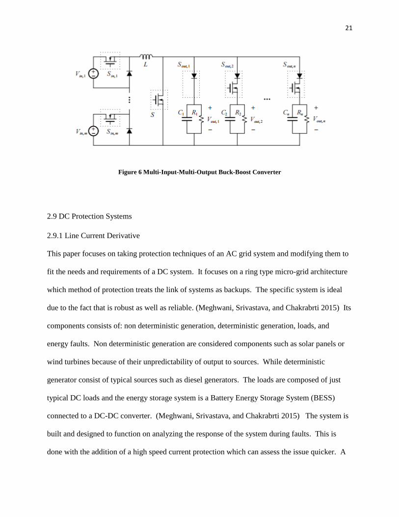
2.8 Multi-Input-Multi-Output DC-DC Converter (MIMO)
MIMO converters are considered before anything cost effective. Compared to a SISO a MIMO
is a better choice being that it wouldn’t have to connect to a DC bus system.(Behjati and
Devoudi 2013) Other advantages of this circuit includes fewer components, higher power density
and location of centralized control. In most cases MIMO is considered an extension of (SISO)
which involves the rearranging and combing of components to give the outcome of a single
complex circuit. As supposed to numerous amounts of simple single circuits.
This converter much like the MISO combines various power sources, and gives an output.
Although, the output for this converter differs. It takes the input and sends them to a different
individual load, thus giving each load its own voltage. This complex converter can also double
and triple the ratio of inputs to outputs. In Figure 6 a MIMO buck-boost converter is displayed
showing two inputs and three outputs. The final output voltage reads Voutn, which is displayed
to show a MIMO’s ability to power an infinite amount of loads contingent on the inputs.
21
Figure 6 Multi-Input-Multi-Output Buck-Boost Converter
2.9 DC Protection Systems
2.9.1 Line Current Derivative
This paper focuses on taking protection techniques of an AC grid system and modifying them to
fit the needs and requirements of a DC system. It focuses on a ring type micro-grid architecture
which method of protection treats the link of systems as backups. The specific system is ideal
due to the fact that is robust as well as reliable. (Meghwani, Srivastava, and Chakrabrti 2015) Its
components consists of: non deterministic generation, deterministic generation, loads, and
energy faults. Non deterministic generation are considered components such as solar panels or
wind turbines because of their unpredictability of output to sources. While deterministic
generator consist of typical sources such as diesel generators. The loads are composed of just
typical DC loads and the energy storage system is a Battery Energy Storage System (BESS)
connected to a DC-DC converter. (Meghwani, Srivastava, and Chakrabrti 2015) The system is
built and designed to function on analyzing the response of the system during faults. This is
done with the addition of a high speed current protection which can assess the issue quicker. A

22
protective device was added in the form of a digital relay to a circuit breaker. This relay asks a
transformer of the signal measured from analog to digital as well as provides an option to change
directions of the signal in case a fault occurs. This change of direction is broken up into two
types of coordination: a primary and a backup. The primary protection takes the 2 lines of
communication and separates the line with a fault and then transfers the entire signal through one
line. The backup is activated if the primary fails and takes the signal and acts a directional delay
thus pushing the signal back towards the bus for protection. The forms of protection.
2.9.2 Control Power Sequencing
In (Cairoli, Kondratiev, and Dougal, 2011) electronic power converters in combination with
mechanical contractors to solve short circuit faults in a nano-grid system. The fault in this
system is solved within roughly 8 milliseconds thus making a more effective strategy than of
traditional fault solving techniques. The condition is improved through the assistance of diode
clamping and load capacitors. There are three steps that occur when handling a fault in a nano-
grid systems through the contractors and power converter. First, the feed of the converters into
the system are shut off. Then the contractor then separates the faulted branch which decreases
the systems current faster. Lastly, the contractors make adjustments to the system applying
changes different from those that caused the fault and then re-energizes the nano-grid. There
exist parameters also known as fault dynamics that effect the way in which faults are handled.
The system if the model during faults shows the phases in of identification in the form of
function of the model as a whole. This includes, fault identification, bus de-energizing, fault
branch isolation, and bus-re-energizing. (Cairoli, Kondratiev, and Dougal, 2011) There is also
fault currents which occurs in the second phase of faults, bus- de-energizing. During this time

23
energy has depleted form the primary source and seeks a solution through the inductance of the
system. Finally, the timing of the opening of the contractor and its dynamics. The timing of the
contractor interacting with the power converter induces the stage of bus re-energizing. When
opened properly the arc voltage across the contractor decreases the fault current and assists in
reconfiguration of the system through the resistance and inductance. The protection of the
system focuses on transient behavior, time or operation as well as quality of power being
delivered. These characteristics control faults and the methods in which they are to be handled.
This exemplifies the method of protection through power sequencing for a dc nano-grid system.
2.9.3 Differential Protection Strategy
(Dhar, Patnaik, and Dash, 2016) Uses a new fast fault detection for Multitermial DC (MTDC)
distribution network for a micro-grid with power electronic based loads. Furthermore, as backup
protection arc fault circuit interrupters are added to detect arc series faults. Essential constraints
that must be fixed in unit protection consist of fast fault detection and fault distance reliability.
(Dhar, Patnaik, and Dash, 2016) Implements a fast fault detection system that works in solving
these two constraints. This MTDC includes multiple PV panels, a diesel generator and various
DC loads. The plan for fault protection is used when the PV panels are considered pole to
ground to fault. Which differs from the hazardous pole to pole distribution in DC systems.
During the occurrence of the fault the voltage and current through the cable change. This should
be detected effectively using the cumulative sum average (CuSum) (Dhar, Patnaik, and Dash,
2016) which helps determines the fault type. This can be determined by either a sample by
sample or window by window approach. Which is the comparison a one sample to a previous
sample or the comparison of a lump of samples (window) to a previous window. In regards to

24
the distance of the fault the new fast fault detection uses the Moore- Penrose method. The
Moore- Penrose method consist of limiting calculations by early detection of voltage and current
through adding uncertainties without a unique solution. (Dhar, Patnaik, and Dash, 2016) The
fast fault detection is considered to be effective in comparison through conventional methods
using CuSum and Moore-Penrose which reduces time in calculations and increases efficiency.
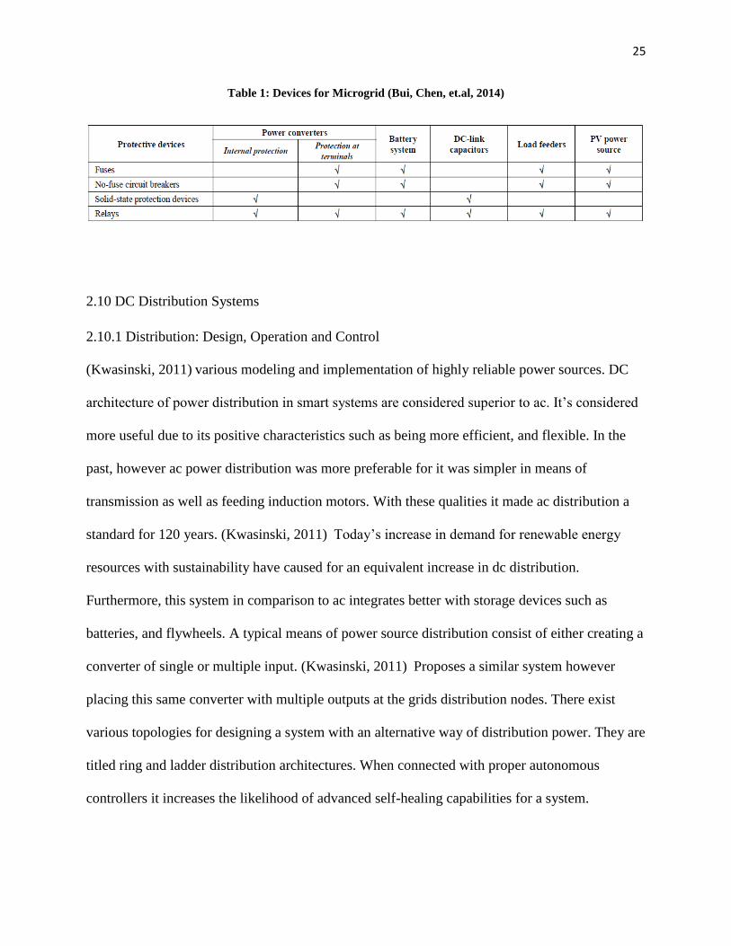
2.9.4 Coordination Strategies and Effective Protection Coordination System
There exist fault detection methods including line to line and line-to ground fault types in a
micro-grid. (Bui, Chen, et.al, 2014) It also reviews the strengths and weaknesses of the main
types of protection devices. Strategies can be created for these devices to secure the longevity as
well as the protection of micro-grid system. .Line to line and line to ground fault are considered
the two faults in this system. This happens in many systems involving renewable energy
resources with battery storage units. These also occur due to those same sources acting with
converters thus creating a line to line faults. There are different methods used to handle faults in
micro-grids. The common fault detection methods are divided into two protection types: unit
and non-unit. (Bui, Chen, et.al, 2014) Unit protection works only under the bounded zone of
the micro-grid. While non-unit protection focuses on everything outside the micro-grid and any
damaged threshold. Furthermore, it act as a back-up form connected systems. Other methods
are determined by location of a faults which can be either at the bus, feeder, or ground or a
system. (Bui, Chen, et.al, 2014) Goes further to show which devices work best in different
components of a micro-grid. Table 1 shows these devices.
25
Table 1: Devices for Microgrid (Bui, Chen, et.al, 2014)
2.10 DC Distribution Systems
2.10.1 Distribution: Design, Operation and Control
(Kwasinski, 2011) various modeling and implementation of highly reliable power sources. DC
architecture of power distribution in smart systems are considered superior to ac. It’s considered
more useful due to its positive characteristics such as being more efficient, and flexible. In the
past, however ac power distribution was more preferable for it was simpler in means of
transmission as well as feeding induction motors. With these qualities it made ac distribution a
standard for 120 years. (Kwasinski, 2011) Today’s increase in demand for renewable energy
resources with sustainability have caused for an equivalent increase in dc distribution.
Furthermore, this system in comparison to ac integrates better with storage devices such as
batteries, and flywheels. A typical means of power source distribution consist of either creating a
converter of single or multiple input. (Kwasinski, 2011) Proposes a similar system however
placing this same converter with multiple outputs at the grids distribution nodes. There exist
various topologies for designing a system with an alternative way of distribution power. They are
titled ring and ladder distribution architectures. When connected with proper autonomous
controllers it increases the likelihood of advanced self-healing capabilities for a system.

26
2.10.2 Local Power Distribution for Micro-grids and Nano-grids
(Nordman, Christensen, and Meier 2012) uses a concept called Local Power Distribution (LPD)
where various devices are used in a nano-grid system to then be combined and integrated to form
a bigger micro-grid system. Furthermore, its focus is on creating a balance in supply, demand
and storage in regards to smart grid layouts. Currently, DC power generation and storage is
considered the most practical source in regards to photovoltaic (PV) solar panels. It is also
considered the most efficient when converting from DC/DC. Though efficient there are a few
requirements when designing a thorough and effectively functioning method of power
distribution. You must minimize losses in transmission as well as cost for the components for
methods of distribution (i.e. breakers and inverters). (Nordman, Christensen, and Meier 2012)
Also, all power sources must have the ability to be plugged in for optimum usage as well as
control. These guidelines would increase resiliency in the system. LPD is used as a system to be
integrated into achieving the goal of sufficient and high functioning smart grid system. LPD is
typically used in micro-grid systems which consist of interconnect nano-grid that are in turn all
connected to a local power generation. Nano-grids sit at the center of LPD being known for its
internal storage. To meet the requirements mentioned LPD applied certain aspects to micro-grids
to ensure stable positive results. To minimize losses in transmission it focuses on DC/DC to
conversion only to cut out the losses when converting to AC. Capital costs is decreased by
simply focusing on DC parts which not only more convenient but also smaller. LPD also
prioritizes electricity use, cuts out manual configuration, and easily interconnects electrical
domains.

27
2.11 DC Storage Systems
2.11.1 Decentralized Stored for Smart grid Systems: Micro-grid and Nano-grid
(Bastos, Dragičević, Guerrero, Machado, 2016) Compared to typical as storage devices of high
bandwidth, this topology for storage utilizes batteries and ultracapacitors (UC). In low bandwidth
communication (LBC) the system fails due to slow transient power thus depleting the efficiency
of the battery. Integrating UC’s into the system increases the speed of transient power and a
means of power restoration. Connecting into a DC-link, batteries and UC ‘s use renewable
energy sources to control the absorption and delivery of excess power. Along with these
additions a decentralized control layout is designed that helps with maintaining stability in the
battery and UC. There also lies an incorporation of an AC grid to help assist with relief on the
DC-link. This addition creates a diversified system that can interchange between DC-DC and
DC-AC conversion. The controller of the grid is split into UC currents reference being controlled
by a high pass filter and the battery by a low pass filter. These filters help with the transient
power and its efficiency. (Bastos, Dragičević, Guerrero, Machado, 2016) the high pass filter
helps the UC by subtracting the error of the UC from the output of the high pass filter. And the
low pass filter working with the battery helps to slow down and maintain the systems dynamic.
2.11.2 Multilevel Energy Management System
(Xiao, Wang, and Setyawan, 2016) a distributed control hybrid energy storage system that will
help increase and maintain reliability. This differs from a centralized control system which is the
typical set up of for energy storage. The sharing of storage acts with the combination of low pass
filters for low ramp rates. Combining the system then forms a multilevel storage system

28
consisting of primary and secondary functionality. With the primary control consisting of high
energy storage, and the secondary being bus control and power sharing compensation to
eliminate power deviation and voltage tracking errors. (Xiao, Wang, and Setyawan, 2016)
Using the primary control source sharing of power is almost done autonomously. This however
creates deviation due to transmission line impedance of the bus system. To increase and solidify
a lifetime of application bus restoration is used to improve the power quality. Though the means
of control create a balance of storage a third means of control is used as backup for efficiency.
This tertiary control function uses ultracapacitors as a means of relief when the limits on the state
of charge are too low or high. It acts a form of protection for the storage system.
2.12 DC Architecture
2.12.1 Modeling and Power Flow for Microgrid
(Farooq, Mateen, et al.) A microgrid system is created to strengthen the grid in a community as
well increase power flow. The systems initial set-yup consist of a classic microgrid system using
PV panels as well as a method of generation, storage and to share energy within the system.
However, it additionally uses an islanded DC system with schemes for protection as well as
regulating the power in this system. Allowing the homes in the system to have their own form
power thus allows for the power to be scalable in the system. The PV panels on the house are
connected to a Maximum Power Point Tracking (MPPT) converter. This is used to take the
power from the solar panel and supply it to the DC link. The DC link is connected to a converter
which can either step the voltage up or down. MPPT also acts as an intelligent battery charger
which regulates the amount of power being consumed by controlling the power being drawn
from DC link/grid (Farooq, Mateen, et al.).

29
2.12.2 Distributed Energy Network for Nanogrids
(Werth, Nobuyuki, and Tanaka) the design of an open energy system is used conceptually in
nanogrid homes. Using some key factors from commonly interconnected nanogrids, some
additions are made for more versatility. With PV panels and a battery for storage for each home,
a extension of a net controller allows for energy be transmitted between each home. The net
controller acts more like a software then a physical aspect for the homes. With this open energy
system there wouldn’t be a need for the system to be connected to a basic utility grid unless
homes are on a typical commercial based property (Werth, Nobuyuki, and Tanaka). This system
consists of 2 levels the nanogrid in each of the homes, and the homes connected to the microgrid.
Each of the levels consist of DC components, which brings advantages such as: efficiency equal
to or greater than 90 percent, easier way to merge power, and increase in transmission efficiency.
The hardware architecture involved is split into three components: subsystem design, DC
interconnection between subsystems, and generalization and scalability. Subsystem design
consist of power sources, power loads, and storage devices. Some basic power sources are PV
panels, wind turbines and generators. The loads can be either DC or AC. And for storage
batteries are used but these can alternate as ether or storage device or another method of supply.
The next component is the dc interconnection between subsystems which is done through a local
area network (LAN) line, and bi-directional DC link. The last component is generalization and
scalability. This part expresses there being difference between homes in size as well as
components, and scalability expressing the distance in transmission lines and the amount of

30
power delivered as well as stored. An open energy system acts as method to increase delivery in
a smart grid system.
2.12.3 Radial distribution
In comparison to other distribution types, radial distribution systems are considered the simplest
to design. This being that every load connected is solely connected to the power source. Radial
distribution is considered profitable in systems with low voltages and power supply and battery
are centered. Furthermore, the cost of the system is fairly low. With all these advantages some
cons to radial distribution, are at times the power supply may become heavily loaded if the
voltage is too high. If alterations are made to the supply this could affect loads at further
distances perhaps causing variations in the voltage. Also, if there is a fault that occurs at the
supply the entire system shuts down. The system can only be restored if the one problem is
resolved for it is the only supply for the loads. These disadvantages can be overcome with the
addition of more lines to transmit power as well and adding feeders. However, though simple
additions the cost of the system and its parts makes this less economically friendly.

31
CHAPTER 3: Design Applications for Nano-Grid Systems
3.1 Design of Single-Input-Multi-Output Converter for Nano-Grid Applications
3.1.1 System Configuration
A single input multi output converter will be designed and implemented into a nano-grid. This
application will allow for the powering of a single load for special applications. To reach the
target, several mandatory steps are followed. The proposed converter can generate the voltage
of a low voltage input to controllable levels of boosted output voltage and it can also produce the
inverted output voltage. This dc-dc converter utilizes the properties of voltage clamping and
soft switching based on a coupled inductor. Design of SIMO dc-dc converter along with modes
of operation has been presented using MATLAB / SIMULINK and/or Multisim and/or PSIM for
modeling, design and simulation with any new advanced software for the new type of
semiconductor. The objectives of this design is to get high-efficiency, high step up ratio and
various levels of output voltages. The use of a modified single input multiple output dc-dc
converters can be used to give multi outputs. This converter consist three outputs, That is low
voltage power source is converted into high-voltage dc bus and middle voltage output terminals.
It has only one power switch with the properties of voltage clamping and soft switching. With
these specific modifications they assist in the goal get different level of output voltages, and
multiple outputs, high efficiency power conversion and high step up ratio too. Table 1 lists the
parameters used in the circuit to achieve each output voltage respectively. The first capacitor
value of 10 µF is the auxiliary capacitor which is used initially in the circuit. Along with the
capacitor the process of coupled inducting is used with values with values of 2 mH. Which
helps with the soft switching and voltage clamping process.

32
Table 2: Required Components for SIMO Converter
C L R Vout
10 µf 2 mH Coupled Inductor
(Primary)
200 Ω
13 volts 2 mH Coupled Inductor
(Secondary)
33 µF 1 mH
33 µF
1 mH
1 kΩ
21 Volts
500 µF 500 kΩ 93 Volts
3.1.2 Circuit Equations
In designing a boost converter there are conventional formulas, used to design a boost converter.
Focusing mostly importantly on the input voltage, output voltage, and duty cycle, to start the
assumption is that the capacitor C is large and the voltage across this capacitor does not change.
Also that when your switch is transitioning from open to close the current 𝐼𝐿 is 0, along with the
diode being ideal diode. Now starting with the switch being open performing a KVL we get:

33
(1)
Thus equaling,
(2)
When the switch is closed. When the switch is opened using the same method you get:
(3)
Solving for 𝑉𝑙 using (3),
(4)
(5)
(6)
Using simplifying methods we get:
(7)
(8)

34
From this gives the relationship between the output voltage, input voltage, and duty cycle of a
PWM modulated signal. Figure 7 shows the layout of a conventional converter with additional
loads.
Figure 7. Block Diagram of Proposed Topology
This SIMO converter contains 4 parts: an input circuit, an output voltage low, output voltage mid
and output voltage high. In this design the method of coupled inductors are used in which
voltage clamping and soft switching are utilized to reduce switching and conduction losses.
Using equations (1)-(8) along with some modifications as well as using contributions from the
capacitors and the switch in this situation to get these formulas. We first start with the
acknowledgement of the inductors in circuit 1 inductors showing the relationship between the
coupled inductors as N is the turns ratio and K the coupling coefficient for a transformer with
𝐿𝑚𝑝 acting as the primary inductor and 𝐿𝑘𝑝 the secondary inductor[4] [6]:

35
(9)
(10)
With respect to the capacitor 𝐶𝑎𝑢𝑥 is taking calculated using:
(11)
The coupled inductor component can be modeled as follows in relation to the voltage
(12)
(13)
Resistance maximum and minimum considerations are used in regards to reaching to expected
outputs for the converter in (14) and (15):
(14)
(15)
The resonant frequency were calculated as
(16)

36
Using the formula used to calculate the duty cycle (17) we rearrange some variables and in turn
put it with respect to efficiency or eff and get (18)
(17)
(18)
3.1.3 Modes of Operation
Mode 1:
In this mode the MOSFET is turned ON and D3 is OFF. Due to the polarity of the coupled
inductor the terminal then becomes positive, thus charges to the middle inductor L3. After
discharging completely and the conclusion of this mode Diode 2 turns OFF.
Mode 2:
In mode 2 the switch is OFF. The current loss coming from the secondary inductor 𝐿𝑘𝑝 . When
the voltage across the switch increases to more than the voltage moving across 𝐶𝑎𝑢𝑥 this is
moved to L4 which causes D1 to conduct. L3 supplies D2, also causing it to discharge due to all
energy being absorbed from the secondary side.

37
Mode 3:
In mode 3 the MOSFET or switch is then triggered. In this 𝐶𝑎𝑢𝑥 and secondary inductor
windings are all in series which releases energy through D3. The switch is now ON, soft
switching is used which leads to a reduction in losses during the switching process. During the
end of the mode the secondary current decays to zero, and the switching cycle repeats starting at
Mode 1.
3.2 Ring Scheme Architecture and Decentralized Supply
3.2.1 Architecture Background
The ring architecture is taking a nanogrid and interconnecting it to other homes with nanogrid
systems to create a microgrid. There exist two types of architecture for the systems: distributed
generation distributed storage architecture (DGDSA) and centralized storage centralized storage
architecture (CGCSA). It furthermore explains how DGDSA is more efficient due to less line
which decreases losses and decreases voltage drop. A CGCSA system uses a photovoltaic (PV)
panel but simply allows generation in one direction to the each home in the system using a
shared power source. In regards to storage the placement of a battery to be used as storage could
create boundaries in which each home would receive power. With this limitation the
methodology and design for the system only allows for one out on each home. These now
complex designs of a system allow for loss in power, as well as decrease in transmission. The
design of DSDGA as shown in Figure 8, shows a system in which each house generates its own
power through (PV) panels. Which gives these homes the ability to generate, store its own power
as well allow for these two things to operate and function bi-directionally through a nanogrid

38
system design. Using its bi-directional abilities, these homes have the flexibility to naturally
handle power in any sort the system needs.
Figure 8. Basic Ring Architecture
3.2.2 Optimal Power Flow Equations for Decentralized Architecture
Optimal power flow focuses on a process that will assist with reduction in cost as well as losses
in transmission through power supply in network settings. With DC nanogrids being the goal and
having such an abundance of positives that is the focus of this optimal power flow. The
algorithm used is the basic DC Optimal power Flow formulas. With 𝑥 representing the number
of units, the outputs 𝑝 and the buses voltage angle by 𝜃. The functions are ℎ(𝑥) and g(x) are the
balanced and unbalanced constraints. (Kargarian, Mohammadi, et.al) (19) - (21) Highlight
functions that include the cost regulation, the load buses, and generating units.

39
(19)
(20)
(21)
40
CHAPTER 4: EXPERIMAENTAL RESULTS AND FINDINGS
4.1 DC-DC Converter Results
4.1.1 Boost Converter Design
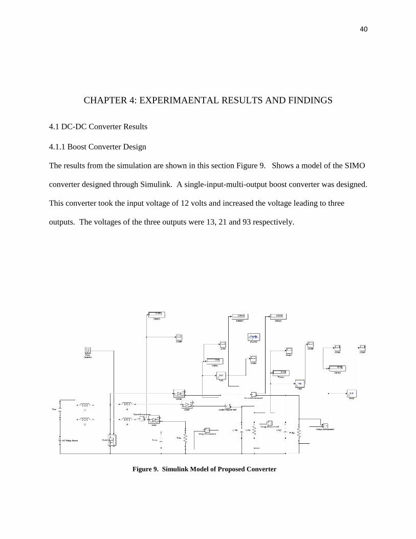
The results from the simulation are shown in this section Figure 9. Shows a model of the SIMO
converter designed through Simulink. A single-input-multi-output boost converter was designed.
This converter took the input voltage of 12 volts and increased the voltage leading to three
outputs. The voltages of the three outputs were 13, 21 and 93 respectively.
Figure 9. Simulink Model of Proposed Converter
41
4.1.2 SIMO Converter and Nano-grid Application
The power source of the SIMO converter consist of photovoltaic (PV) cells. This renewable
energy source is modeled as a 12V DC power source for accuracy in design of the converter.
Using a PV panel provides energy efficiency as well as a self-sufficient power source. Reference
[10] Nano-grids consist of DC sources which removes the need of inverters for generators. The
converter will be connected to the controller of the nano-grid system which will be used to
distribute the voltage throughout the system. In sending power throughout the Modes of the
converter are activated accordingly. The Loads of the system receive the input and reach their
respective values. Furthermore, the nano-grid would deliver power according to the amounts
demanded by each load. This is in relation to the gateways of the grid. One way of function on
the gateways involves power exchange in combination with the controller. The other way of
communication is through layers to either through Universal Serius Bus (USB) or Power over
Ethernet (POE)

42
4.1.3 Results from SIMO Converter
Figure 10 shows the pulses delivered from the generator being delivered into the switch of the
circuit.

43
Figure 10. Pulses from the Generator
Figures 11, 12, and 13 show the output voltages achieved resulting in 13, 21 and 93 volts. With
Figure 10 the voltage rises to approximately 23 volts then settles to our desired value of 13 volts.
Figure 11. Output Voltage of 13 volts

44
Similar to Figure 10, the voltage in Figure 11, of 21 is our expected goal, however output begins
to surpass that value and peaks at 29 volts later to settle at our intended value of 21 volts.
Figure 12. Output voltage of 21 volts

45
Due to the layout of the circuit the output of Figure 12 is different. It increases to a value of 93
volts and then remaining there consistently throughout the time the circuit remains active.
Figure 13. Output Voltage of 93 volts
Along with the voltage being married across the resistors the current is also calculated. The
current in this design is measured across each output and which also has the resistances are
across each load. Figure 14-16 shows the various currents if the system. Each graph shows a
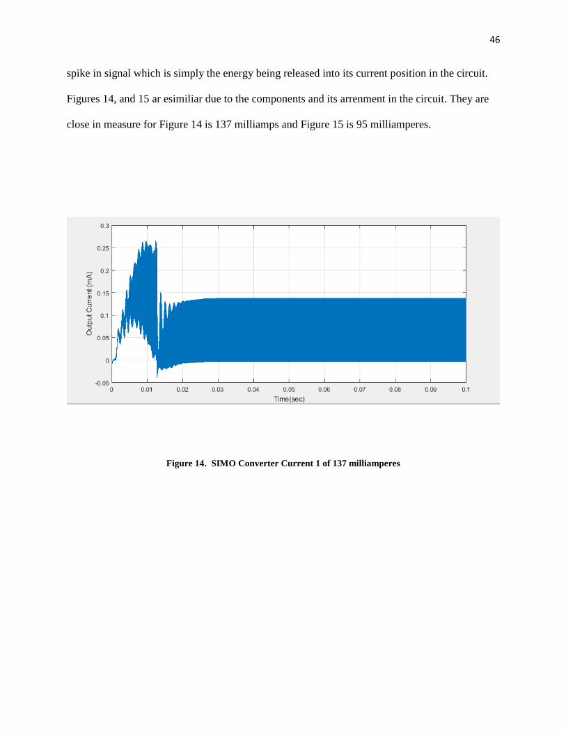
46
spike in signal which is simply the energy being released into its current position in the circuit.
Figures 14, and 15 ar esimiliar due to the components and its arrenment in the circuit. They are
close in measure for Figure 14 is 137 milliamps and Figure 15 is 95 milliamperes.
Figure 14. SIMO Converter Current 1 of 137 milliamperes

47
Figure 15. SIMO Converter Current 2 of 95 milliamperes
The results in Figure 16 is the lowest due to losses in progression giving it the results of 66
milliamperes.

48
Figure 16. SIMO Converter Current 3 of 25 milliamperes
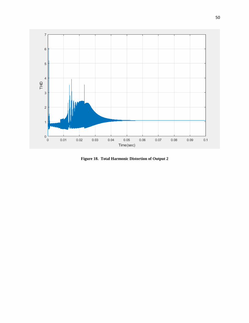
Figures 17-19 show the totla harmonic distoriton from each of the three outputs. Which shows
over a time a decrease in THD due to the addition of compoenents during progression through
the circuit.

49
Figure 17. Total Harmonic Distortion of Output 1.
50
Figure 18. Total Harmonic Distortion of Output 2

51
Figure 19. Total Harmonic Distortion of Output 3
4.2 Ring Architecture Layout
The layout of the ring architecture forms a microgrid system. The modified version of a
microgrid, the ring architecture is created as shown in Figure 20.

52
Figure 20. Ring Architecture Simulink Model

53
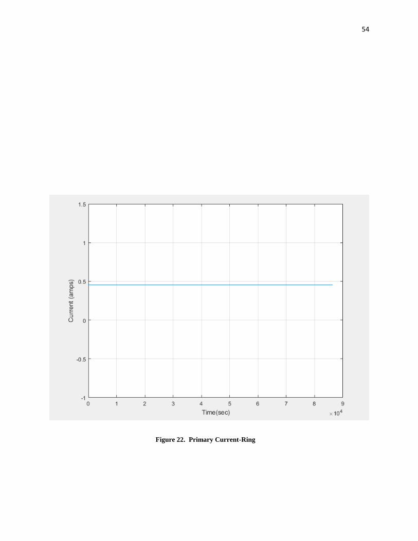
4.2.1 Results from Ring Layout
This model contains three loads in the form of homes connected to a photovoltaic panel and a
battery. The battery acts a storage as well as a method to dump energy when necessary. Figure
21 shows the primary voltage averaging around 200 kilovolts and the primary current in Figure
22 peaking at 1750 kilo amperes.
Figure 21. Primary Voltage-Ring
54
Figure 22. Primary Current-Ring
55
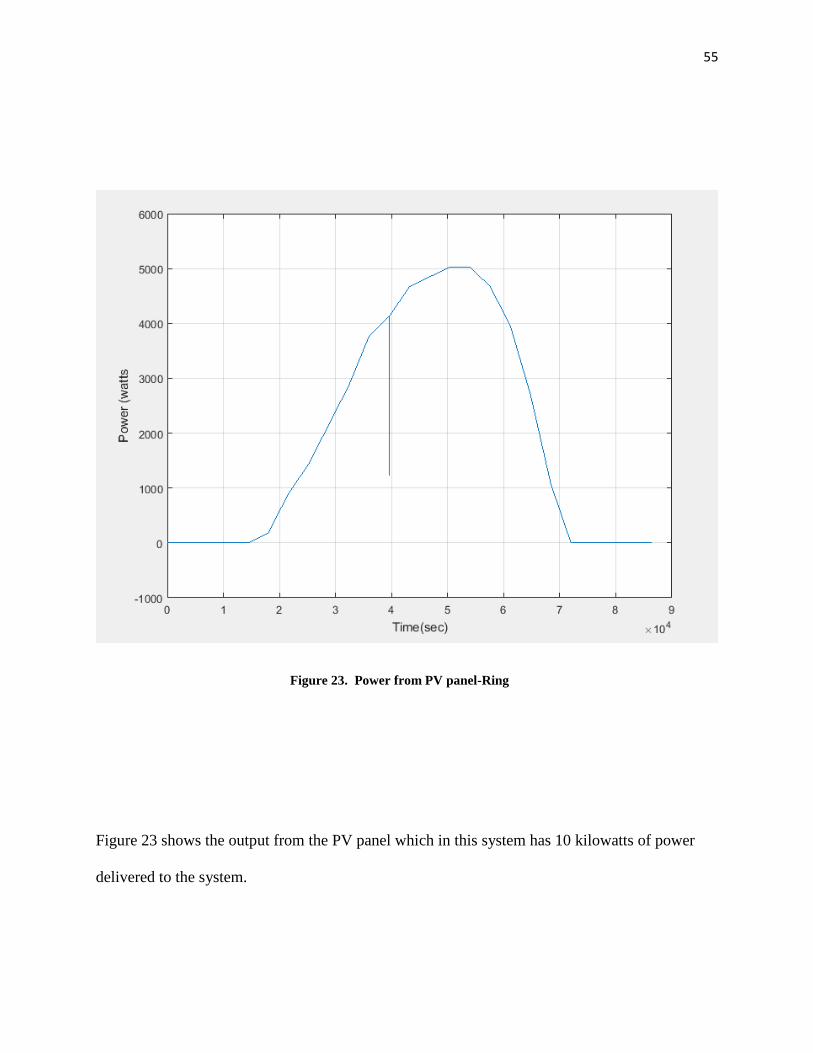
Figure 23. Power from PV panel-Ring
Figure 23 shows the output from the PV panel which in this system has 10 kilowatts of power
delivered to the system.
56
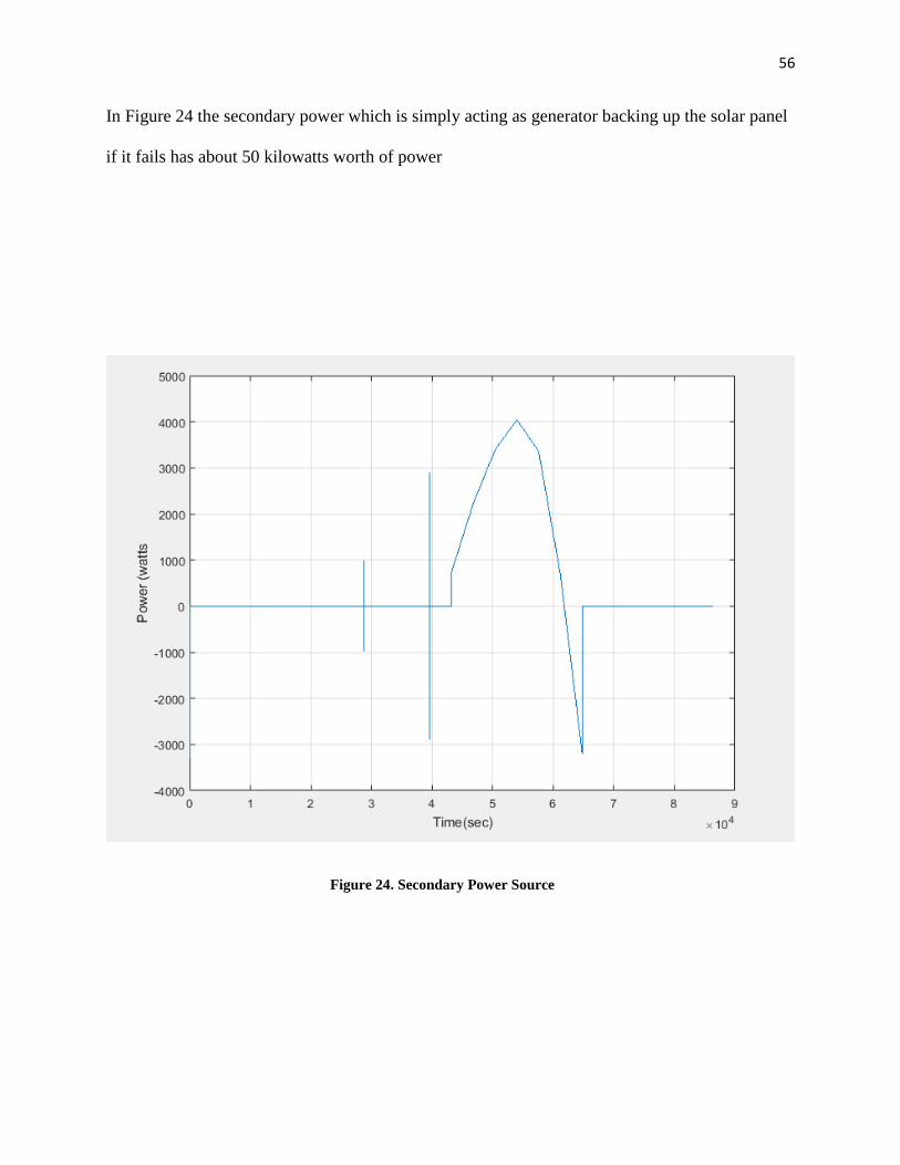
In Figure 24 the secondary power which is simply acting as generator backing up the solar panel
if it fails has about 50 kilowatts worth of power
Figure 24. Secondary Power Source

57
Figure 25. Average Load Output-Ring
The average loads in the system is 80 kilowatts which sits right below the average for a nanogrid
system which is 100 kilowatts which is in Figure 25.
Figure 26 shows the amount of voltage battery is low. This being because the PV panel is
supposed to be the main power source thus limiting the necessity of a battery. The battery mostly

58
acts a backup to the secondary due to the fact that the PV panel is the initial power source and its
secondary are used to keep up the functionality.
Figure 26. Power from Battery-Ring

59
4.3 Radial Architecture Layout
The radial layout consist if each load being directly connected to the PV panel. Though the
battery still exist it works only with the PV panel. Causing the loads to rely heavily on the panel.
Figure 24 shows the radial architecture.
Figure 27. Radial Architecture Simulink Model

60
4.3.1 Results from Radial Layout
The primary voltage in Figure 28 approximately 9 kilowatts. This comes from the system having
the component such as the battery directly connected to solely the solar panel and not the loads.
This helps boost the primary voltage of a system.
Figure 28. Primary Voltage-Radial

61
Furthermore the current shows a steady output current for the PV panel. It also shows no positive
response for the secondary source which is also affected by the layout and the setup of the
homes.
Figure 29. Primary Current-Radial
62
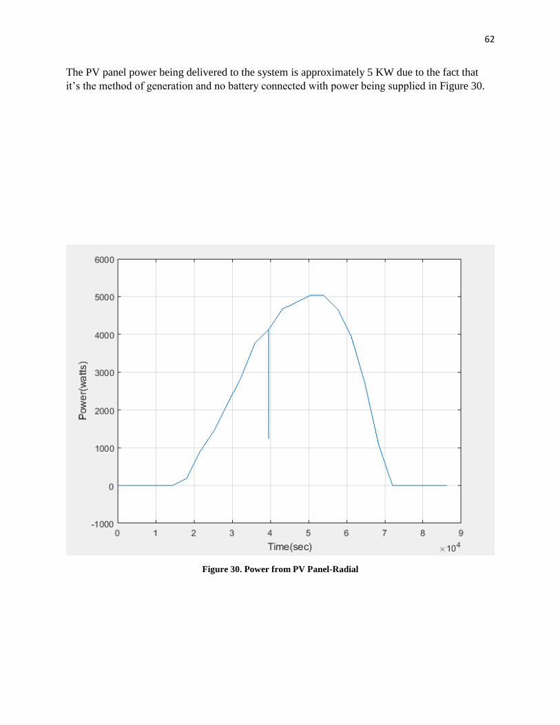
The PV panel power being delivered to the system is approximately 5 KW due to the fact that
it’s the method of generation and no battery connected with power being supplied in Figure 30.
Figure 30. Power from PV Panel-Radial

63
CHAPTER 5: CONCLUSION AND RECOMMENDATIONS
5.1 Conclusion
The novel approach to create a converter that can take a one input and converter it into numerous
outputs was the goal of this paper. As shown in this paper, success in designing a DC-DC
converter with this criteria was achieved. This included designing a converter receiving a single
input voltage for usage of a nano-grid. The single input leads to outputs where each are loads of
different values. With these successful results allowed for the nano-grid to act as a generator.
Furthermore, ring architecture was constructed consisting of nanogrids being interconnected to
create a microgrid. The architecture allows for the system to act as a method of prevention from
loss in power and transmission. It also is a form of protection in relation to faults occurring and
possibly damaging the network. Along with a ring architecture, a radial layout was also
designed to act as a comparison to the ring layout. Thought a radial layout is simpler design it
has a lot of drawbacks. Along with needing extra cables to increase efficiency, if ever the PV
panel was to shut down it would result in the entire system shutting down. While the ring layout
requires less cables as well a backup method in case an outage occurs. Thus making the ring
layout the best choice in regards to microgrid design using nanogrid systems.
5.2 Recommendations for Future Work
• Implementation of the nano-grid in homes
• Emphasize on the ability of a nano-grid to function as power generator by adding
additional inputs.
• Fabricating a circuit to which it would be both complex and distribute power to more
loads.
• Focus on a method to increase current flowing throughout the circuit.

64
• Combine multiple nano-grids to form a micro-grid for applications of higher voltage
loads.
• Design a bus system that can go into further detail of a microgrid system.
• Compare and contrast other architectures to alter methods for optimal power flow and
results.

65
References
Bastos, Renan F., Dragičević, Tomislav Guerrero, Josep M., Machado, Ricardo. Q,
“Decentralized Control for Renewable DC Microgrid with Composite Energy Storage System
and UC Voltage Restoration Connected to the Grid,” (2016): 2016-2021
Bryan, J., Duke, R., Round, S., "Decentralized generator scheduling in a nanogrid using DC bus
signaling," Power Engineering Society General Meeting (2004): 977-985.
Bui, Duong Minh, Chen, Shi-Lin, Wu, Chi-Hua, Lien, Keng-Yu, Huang, Chen-Ho, Jen, Kuo-
Kuang, “Review on Protection Coordination Strategies and Development of An Effective
Protection Coordination System for DC Microgrid,” (2014)
Cairoli P., Kondratiev, I. and Dougal, R. A., “Controlled Power Sequencing for Fault Protection
in DC Nanogrids,” (2011): 730-738.
Chen, D., Xu, L., Yao, L., "DC Voltage Variation Based Autonomous Control of DC
Microgrids," Power Delivery, IEEE Transactions 28.2 (2013): 637-648.
Dhar, Snehamoy, Patnaik, R. K., Dash, P.K., “Fault Detection and Location of Photovoltaic
Based DC Microgrid Using Differential Protection Strategy,” (2016)
Dongwon Kwon, Graduate Student Member, IEEE, and Gabriel A. Rincón-Mora, Senior
Member, IEEE,“Single-Inductor–Multiple-Output Switching DC–DC Converters,” IEEE
transactions on circuits and systems 56.8 (2009).
Farhangi, Hassan. "The Path of the Smart Grid." IEEE Power and Energy (2010).
Farooq, Rabiya; Mateen, Laeeq; Ahmad, Masab; Akbar, Syeda Q; Khan, Hassan A; Zaffar,
Nauman A., “SMART DC MICROGRIDS: Modeling and Power Flow analysis of a DC
Microgrid for off-grid and weak-grid connected communities,” (2014)
H. Behjati and A. Davoudi, “A multiple-input multiple-output DC–DC converter,” IEEE
Transactions on Industry Applications 49.3(2013): 1464-1479.
H. Behjati and A. Davoudi, “Power budgeting between diversified energy sources and loads
using a multiple-input multiple-output DC–DC converter,” IEEE Transactions on Industry
Applications 49.6 (2013): 2761-2772.
H. Matsuo, W. Lin, F. Kurokawa, T. Shigemizu, and N. Watanabe, “Characteristics of the
multiple-input DC–DC converter,” IEEE Transactions on Industrial Electronics 51.3 (2004):
625-631.
H R, Thasreef, Siny Paul, and Annie P Oommen. "Controlled Voltage Single Input- Multiple
Output DC to DC Converter." International Journal of Advanced Research Electrical,
Electronics, and Instrumentation Engineering 3.5 (2014).

66
Ito, Youichi, Yang Zhongqing, and Hirofumi Akagi. "DC microgrid based distribution power
generation system." Power Electronics and Motion Control Conference, 2004. IPEMC 2004.
The 4th International 3 IEEE, (2004).
K. Sun, L. Zhang, Y. Xing, Guerrero, J.M., "A Distributed Control Strategy Based on DC Bus
Signaling for Modular Photovoltaic Generation Systems With Battery Energy Storage," Power
Electronics, IEEE Transactions 26.10 (2011).
Kargarian, A., Mohammadi, J., Guo, J., Chakrabarti, S., Barati, M., Hug, G., Kar, S., and
Baldick, R., “Toward Distributed/ Decentralized DC Optimal Power Flow Implementation in
Future Electric Power Systems,” IEEE Transactions on Smart Grids (2016)
Karthik, S., C. Jegan, and R. Ilango. "Design of A Single Input Multiple Output DC-DC
Converter." International Journal of Engineering and Management Research 4.2 (2014): 22-28.
Kwasinski, Alexis, “Advanced power electronics enabled distribution architectures: design,
operation, and control,” 8th International Conference on Power Electronics - ECCE Asia (2011):
1484-1491.
L. K. Gummi and M. Ferdowsi, “Double-input DC–DC power electronic converters for
electric-drive vehicles—topology exploration and synthesis using a single-pole triple-throw
switch.” IEEE Transactions on Industry Applications 57.2 (2010): 617-623.
L. Solero, A. Lidozzi, and J. A. Pomilio, “Design of multiple-input power converter for hybrid
vehicles,” IEEE Transactions on Power Electronics 20.5 (2005): 1007-1016.
LBNL. The Microgrid Concept. Available:
http://der.lbl.gov/research/microgrid-concept.
Lee, Fred C., Dushan Boroyevich, Paolo Mattavelli, and Khai Ngo. "Renewable Energy and
Nanogrids." Center for Power Electronics Systems (2010).
Loh, P.C., Ding Li, Yi Kang Chai, and Blaabjerg, F., "Autonomous Operation of Hybrid
Microgrid With AC and DC Subgrids," Power Electronics, IEEE Transactions 28.5 (2013):
2214-2223.
Meghwani, A, Srivastava, S. C., Chakrabarti, S, “A New Protection Scheme for DC Microgrid
using Line Current Derivative,” (2015): 1-5.
Moussaoui, Zaki, Jifeng Qin, and Greg Miller. "Single Inductor Dual Output Dc-dc Converter
for Space-limited or Large Input Voltage Variation Systems." 2010 IEEE 12th Workshop on
Control and Modeling for Power Electronics (COMPEL).
67
Nami, F. Zare; A. Ghosh, and F. Blaabjerg, “Multiple-output DC–DC converters based on
diode-clamped converters configuration: Topology and control strategy,” IET Power Electron.
3.2 (2010): 197-208.
Nasir, Mashood; Zaffar, Nauman A., and Khan, Hassan A. “Analysis on Central and Distributed
Architectures of Solar Powered DC Microgrids,” (2016)
Nordman, Bruce. "Nanogrids: Evolving Our Electrical Systems from the Bottom up."
Environmental Energy Technologies Division (2010).
Nordman, Bruce, Ken Christensen, and Alan Meier. "Think Globally, Distribute Power Locally:
The Power of Nanogrids." IEEE Green It (2012).
Paul A. Panepinto, “Making Power Adapters Smarter and Greener”,
Greenplug, 2009 IEEE International Symposium on Sustainable Systems and Technology (2009).
Po-Wa Lee; Lee, Y. -S; Bo-Tao Lin, "Power distribution systems for future homes," Power
Electronics and Drive Systems, 1999. PEDS '99. Proceedings of the IEEE 1999 International
Conference (1999): 1140-1146.
R. H. Lasseter, Microgrids, IEEE Power Engineering Society Winter
Meeting 1(2002):305-308.
Rizzo, Renato; Pietro Tricoli, and Ivan Spina. "An Innovative Reconfigurable Integrated
Converter Topology Suitable for Distributed Generation." Energies (2012): 3640-654.
S. Falcones, R. Ayyanar, and X. Mao, “A DC–DC multiport-converter-based solid-state
transformer integrating distributed generation and storage,” IEEE Transactions on Power
Electronics 28.5 (2013): 2192-2203.
Schonberger, J., Duke, R., Round, S.D., "DC-Bus Signaling: A Distributed Control Strategy for a
Hybrid Renewable Nanogrid," Industrial Electronics, IEEE Transactions 53.5 (2006): 1453-
1460.
Tong, Yajian, and Juri Jatskevich. "A Methodology to Derive Single-stage Multiple-input
Multiple-output DC-DC Converters." 2014 IEEE 36th International Telecommunications Energy
Conference (INTELEC).
Wai, Rong-Jong, and Kun-Huai Jheng. "High-Efficiency Single-Input Multiple-Output DC–DC
Converter." IEEE Transactions on Power Electronics IEEE Trans. Power Electron.: 886-98.
Werth, Annette; Kitamura, Nobuyuki and Tanaka, Kenji, “Conceptual Study for Open Energy
Systems: Distributed Energy Network Using Interconnected DC Nanogrids,” IEEE Transactions
on Smart Grids 6.4 (2015): 1621-1630.

68
Xiao, Jianfang, Wang, Peng, and Setyawan, Leonardy, “Multilevel Energy Management System
for Hybridization of Energy Storages in DC Microgrids,” IEEE Transactions on Smart Grids 7.2
(2016): 847-856