Embed Size (px)
Citation preview
Int. J. Adv. Res. Sci. Technol. Volume 3, Issue3, 2014, pp.163-171
www.ijarst.com Praveen Kumar. et. al Page | 163
International Journal of Advanced Research in Science and Technology
journal homepage: w w w .ijarst.com
ISSN 2319 – 1783 (Print)
ISSN 2320 – 1126 (Online)
Design and Simulation of 256 bit 64-point FFT Using RADIX 4 Algorithm
K. Praveen Kumar 1*, M. Srinivasarao
2 and K. Venugopal
3
Dept. Electronics and Communication Engineering,
Avanthi’s St. Theressa Institute of Engineering and Technology, Andhra Pradesh, India.
*Corresponding Author’s Email: [email protected]
A R T I C L E I N F O
A B S T R A C T
Article history:
Received
Accepted
Available online
01 Oct. 2014
12 Nov. 2014
21 Nov. 2014
A Parallel and pipelined Fast Fourier transform(FFT) processor for use in
the orthogonal frequency division multiplexer .it is important to develop a
high performance FFT processor to meet the requirements of the real time
and low cost in many different systems. Un like being stored in the
traditional ROM, the twiddle factors in our pipelined FFT processor can be
accessed directly. here we simulated and synthesized the 256 bit 64 point
FFT with radix 4 using VHDL coding and simulation and synthesis done by
Modelsim ISE and Xilinx ISE design suite respectively.
© 2014 International Journal of Advanced Research in Science and Technology (IJARST), All rights reserved.
Keywords:
DIT FFT, DIF FFT,
BUTTERFLY,
RADIX, OFDM.
Introduction:
Fast Fourier Transform (FFT) processor is widely
used in different applications, such as WLAN, image
process, spectrum measurements, radar and multimedia
communication services [1]. However, the FFT
algorithm is a demanding task and it must be precisely
designed to get an efficient implementation. If the FFT
processor is made flexible and fast enough, a portable
device equipped with wireless transmission system is
feasible. Therefore, an efficient FFT processor is
required for real-time operations [2] and designing a
fast FFT processor is a matter of great significance.
Active and passive radar systems are two
commonly used radar systems in different military and
nonmilitary applications respectively. Active radar
systems are commonly used in military and commercial
applications for the detection and tracking of objects
through a medium such as air. Most active radar
systems work by transmitting a signal pulse through the
medium scatters off objects in the medium. by
processing the received wave field, an active radar
system can determine an object's distance, velocity, and
other features. The passive detection of objects has
become of particular interest to the military in scenarios
where the medium needs to be monitored covertly. A
passive radar system can consist solely of an array of
receiving antennas as opposed to an active radar system
with a co-located transmitter and receiver. Without a
transmitter the passive radar system relies on other
sources of electromagnetic waves, such as am or fm
radio waves, t v broadcast, nearby radar, cell towers, or
a wideband waveform to “illuminate” objects in the
medium [3]. An active radar system has the benefit of a
known transmit waveform. A passive radar system does
not have knowledge of the transmitted signal and thus
has to rely on digital signal processing techniques to
extract information from an array of sensors over a
period of time.
Fig: 1. Radar system
The system is divided in a transmission section and
a reception section in modem communication systems
Orthogonal Frequency Division Multiple (OFDM)
plays a crucial role and it will be replaced by
Orthogonal Frequency Division Multiple Access
(OFDMA) in the next generation wireless
communication systems such as WiMAX and 3G-LTE
standard.
The fastness of the system depends on their intra
and inter peripherals, the intra peripherals depends on
the designers choice and the inter peripherals depends
on the users choice. Designers choice includes
components, algorithms etc, users choice includes
inputs, external devices, signals etc. The previous
project had focused on radix-2 algorithm which has
more delay. To overcome this problem there is a need
Int. J. Adv. Res. Sci. Technol. Volume 3, Issue3, 2014, pp.163-171
www.ijarst.com Praveen Kumar. et. al Page | 164
to change in the algorithm majorly, the present project
deals with change in the algorithm called radix-4
algorithm and focus on the design and implementation
of 256-bits 64-points Fast Fourier Transform (FFT) for
a Field Programmable Gate Array (FPGA) kit. The
coding is done in VHDL, simulation and synthesis can
be done by using Model SIM ISE and Xilinx ISE
Design Suite respectively.
Basic Theory of OFDM:
The Orthogonal Frequency Division Multiplexing
(OFDM) technique is one of the most important
modulation approaches which is used in many schemes
of communication systems such as wireless
communications and networks [4,5]. The benefit of the
OFDM approach rather than other modulation
approaches is the efficient use of bandwidth using
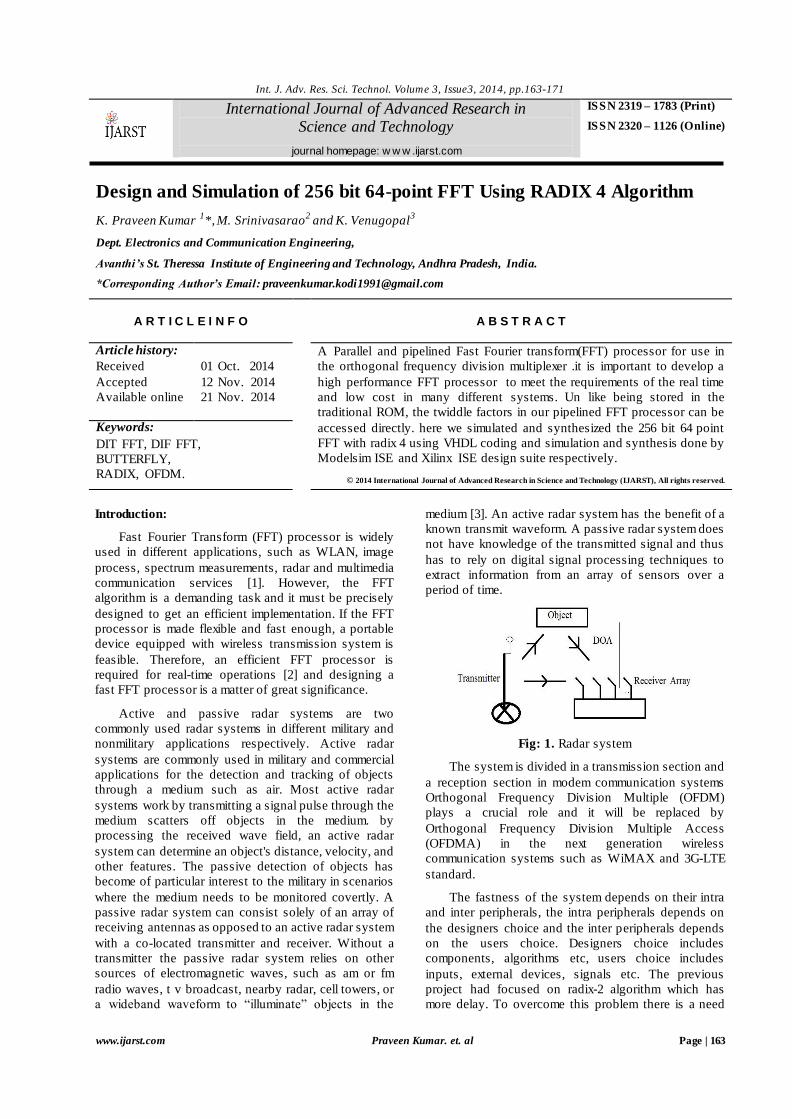
overlapping property. A typical OFDM system consists
of two parts; receiver and transmitter. The receiver has
four important blocks which are serial-to-parallel block,
Inverse Fast Fourier Transform IFFT), QAM table and
the RF block. In the other hand, transmitter has RF
block at the front end, Fast Fourier Transform (FFT),
QAM table and parallel-to-serial block at the back end,
shown in Figures 2(a) and 2(b).
OFDM is a wideband wireless digital communication
technique that is based on block modulation. It is
known as block modulation because the OFDM frame
is split into blocks and each block has Ts duration.
These blocks contain one or more symbols. Each
symbol or group of symbols will be assigned a separate
carrier. The OFDM arranges the subcarriers in such a
way that they do not overlap and maintain the
orthogonality between them. These subcarriers are
modulated independently. All the split information is
then transmitted in parallel through multiple carriers
[6]. In OFDM the carriers can be placed as near as
possible maintaining the orthogonality, thereby making
better utilization of the spectrum. The width of the
pulse puts the limit on the sub-carrier spacing. The
subcarrier spacing will be inversely proportional to the
symbol duration, where symbol durations denoted by
Ts. Longer is the symbol duration, better is the
performance [7].
Algorithm:
The First designed chip is an FFT processor. The
FFT processor has a central position both in the OFDM
transmitter and receiver. The FFT is a computationally
demanding operation that requires an ASIC
implementation to reach high performance, i.e. high
throughput combined with low energy consumption.
The FFT and IFFT Equations has the property that, if
FFT (Re (xi) + jIm(xi)) = Re(Xi)+ jIm(Xi) and
IFFT (Re (Xi) + jIm(Xi)) = Re(xi)+ jIm(xi),
where xi and Xi are N words long sequences of
complex valued, samples and sub-carriers respectively,
then
1/N * FFT(Im(Xi)+ jRe(Xi)) = Im(xi)+ jRe(xi).
Thus, it is only necessary to discuss and implement
the FFT equation. To calculate the inverse transform,
the real and imaginary part of the input and output are
swapped. Since N is a power of two, scaling with 1/N is
the same as right shift the binary word bits. Even
simpler, is to just remember that the binary point has
moved bits to the left. Not performing the bit
shift until, if ever, it is necessary, which depends on
how the output from the IFFT will be used.
Fig: 3.a. A radix-2 DIF butterfly
Int. J. Adv. Res. Sci. Technol. Volume 3, Issue3, 2014, pp.163-171
www.ijarst.com Praveen Kumar. et. al Page | 165
Fig: 3. B. A radix-2 DIT butterfly
The FFT algorithm can be realized with a butterfly
operation as the basic building block. There are two
types of butterfly operations, decimation in time (DIT)
and decimation in frequency (DIF). The difference
between DIT and DIF lies the position of the twiddle
factor multiplication, which is either performed before
or after the subtraction and addition. Since the FFT is
based on divide and conquer, it will be most efficient if
the input sequence is of length N = rp, where N is
called point, r is called radix, and p is a positive integer.
To compute an N-point FFT, p stages of butterflies are
connected.
RADIX 4 Algorithm:
Radix-4 is another FFT algorithm which was
surveyed to improve the speed of functioning by
reducing the computation; this can be obtained by
change the base to 4. For a same number if base
increases the power/index will decreases. For radix-4
the number of stages are reduced to 50% since N=43
(N=4M) i.e. only 3 stages. Radix-4 is having four
inputs and four outputs and it follows in-place
algorithm. The following will explain the functioning of
radix-4 and how the computational complexity is
reduced.
Fig: 4. Basic structure of R4 FFT
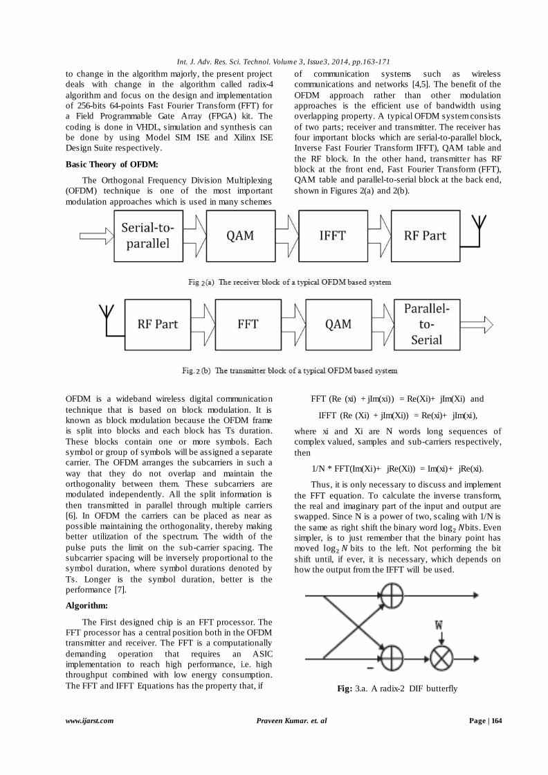
Fig: 5. Basic radix-4 butterfly operation
The Processing Element (PE) of the radix-4-based FFT
algorithms is the 4-point FFT. The four butterfly
outputs (X (0), X (1), X (2) and X (3)) obtained using
inputs (x(0), x(1), x(2) and x(3)) can be performed
using
X (0) = x(0) + x(2) + x(1) + x(3)
X (1) = x(0) − x(2) − j(x(1) − x(3))
X (2) = x(0) + x(2) − x(1) − x(3)
X (3) = x(0) − x(2) + jx(1) − jx(3)
When the decomposition in multiple building
blocks is applied, the N-point FFT is realized by using
several stages each one contains many butterflies. For
N-point FFT, we need s = stages and b =
butterflies per stage. It can be seen that the computation
of the FFTs in the second stage is dependent on the first
stage computation. The same concept is applied to the
computation of the third stage which depends on the
second stage computation. More generally, the data-
dependent computation is observed between successive
stages for N-point FFT. Therefore, two architectures are
possible. The first one is a parallel realization. For N-
point FFT, we need
radix-4 butterflies which
is equivalent to 3
complex multipliers and 8
complex adders. Although this solution does
not make an efficient use of the resources, it is very
simple and offers a higher throughput.
The second realization is a recursive one. Where
the N-point FFT can be performed using one radix-4
butterfly. This architecture is interesting in terms of the
use of arithmetic operators but suffers from a low
operating frequency.
Results:
Simulation results:
Int. J. Adv. Res. Sci. Technol. Volume 3, Issue3, 2014, pp.163-171
www.ijarst.com Praveen Kumar. et. al Page | 166
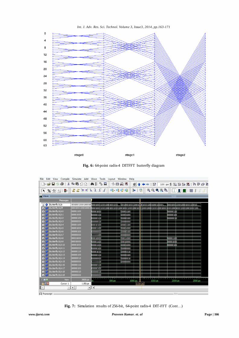
Fig. 6: 64-point radix-4 DITFFT butterfly diagram
Fig. 7: Simulation results of 256-bit, 64-point radix-4 DIT-FFT (Cont…)
Int. J. Adv. Res. Sci. Technol. Volume 3, Issue3, 2014, pp.163-171
www.ijarst.com Praveen Kumar. et. al Page | 167
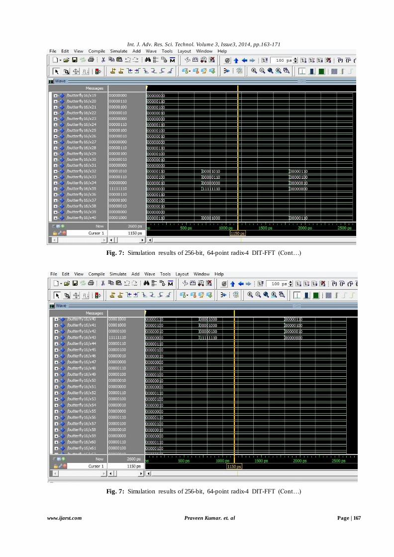
Fig. 7: Simulation results of 256-bit, 64-point radix-4 DIT-FFT (Cont…)
Fig. 7: Simulation results of 256-bit, 64-point radix-4 DIT-FFT (Cont…)
Int. J. Adv. Res. Sci. Technol. Volume 3, Issue3, 2014, pp.163-171
www.ijarst.com Praveen Kumar. et. al Page | 168
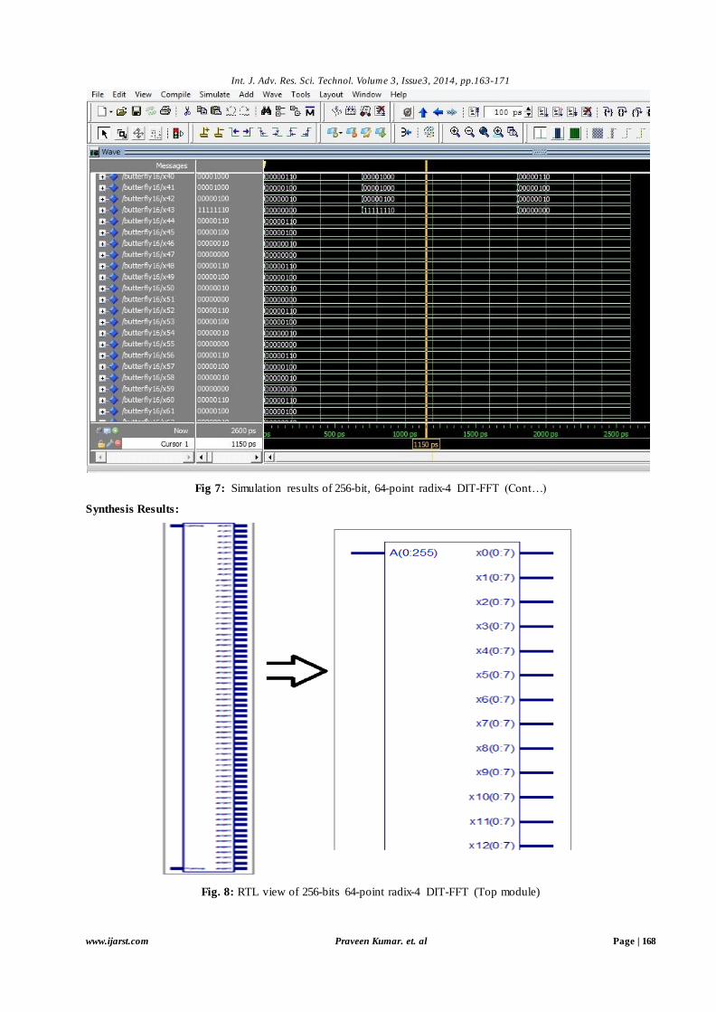
Fig 7: Simulation results of 256-bit, 64-point radix-4 DIT-FFT (Cont…)
Synthesis Results:
Fig. 8: RTL view of 256-bits 64-point radix-4 DIT-FFT (Top module)
Int. J. Adv. Res. Sci. Technol. Volume 3, Issue3, 2014, pp.163-171
www.ijarst.com Praveen Kumar. et. al Page | 169
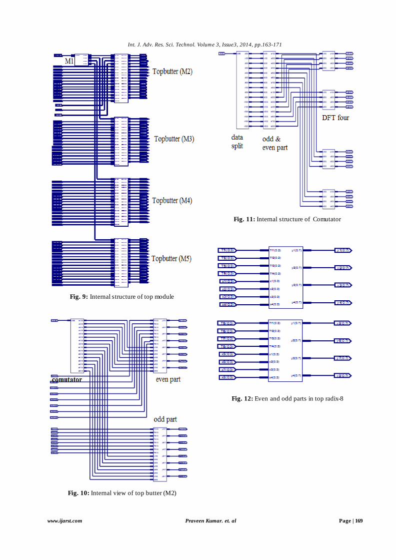
Fig. 9: Internal structure of top module
Fig. 10: Internal view of top butter (M2)
Fig. 11: Internal structure of Comutator
Fig. 12: Even and odd parts in top radix-8
Int. J. Adv. Res. Sci. Technol. Volume 3, Issue3, 2014, pp.163-171
www.ijarst.com Praveen Kumar. et. al Page | 170
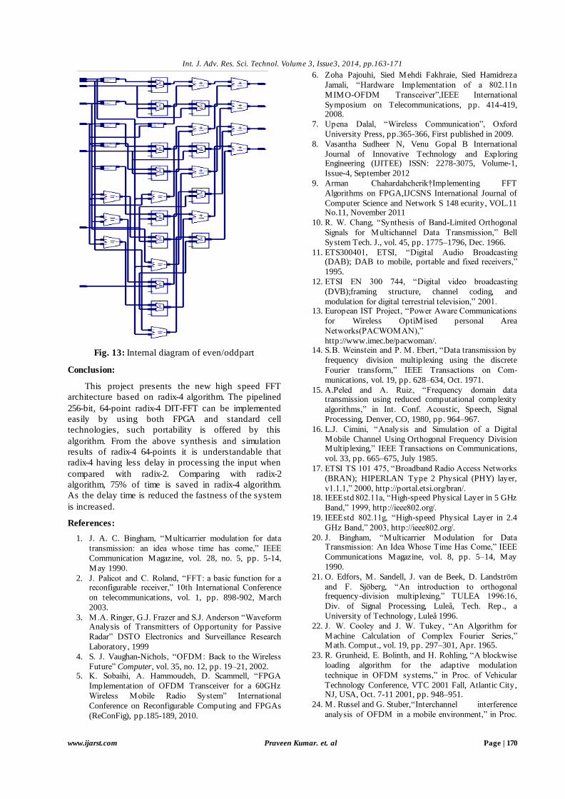
Fig. 13: Internal diagram of even/oddpart
Conclusion:
This project presents the new high speed FFT
architecture based on radix-4 algorithm. The pipelined
256-bit, 64-point radix-4 DIT-FFT can be implemented
easily by using both FPGA and standard cell
technologies, such portability is offered by this
algorithm. From the above synthesis and simulation
results of radix-4 64-points it is understandable that
radix-4 having less delay in processing the input when
compared with radix-2. Comparing with radix-2
algorithm, 75% of time is saved in radix-4 algorithm.
As the delay time is reduced the fastness of the system
is increased.
References:
1. J. A. C. Bingham, “Multicarrier modulation for data
transmission: an idea whose time has come,” IEEE
Communication Magazine, vol. 28, no. 5, pp. 5-14,
May 1990.
2. J. Palicot and C. Roland, “FFT: a basic function for a reconfigurable receiver,” 10th International Conference
on telecommunications, vol. 1, pp. 898-902, March
2003.
3. M.A. Ringer, G.J. Frazer and S.J. Anderson “Waveform Analysis of Transmitters of Opportunity for Passive
Radar” DSTO Electronics and Surveillance Research
Laboratory, 1999
4. S. J. Vaughan-Nichols, “OFDM: Back to the Wireless
Future” Computer, vol. 35, no. 12, pp. 19–21, 2002. 5. K. Sobaihi, A. Hammoudeh, D. Scammell, “FPGA
Implementation of OFDM Transceiver for a 60GHz
Wireless Mobile Radio System” International
Conference on Reconfigurable Computing and FPGAs
(ReConFig), pp.185-189, 2010.
6. Zoha Pajouhi, Sied Mehdi Fakhraie, Sied Hamidreza
Jamali, “Hardware Implementation of a 802.11n
MIMO-OFDM Transceiver”,IEEE International
Symposium on Telecommunications, pp. 414-419, 2008.
7. Upena Dalal, “Wireless Communication”, Oxford
University Press, pp.365-366, First published in 2009.
8. Vasantha Sudheer N, Venu Gopal B International
Journal of Innovative Technology and Exploring Engineering (IJITEE) ISSN: 2278-3075, Volume-1,
Issue-4, September 2012
9. Arman Chahardahcherik†Implementing FFT
Algorithms on FPGA,IJCSNS International Journal of
Computer Science and Network S 148 ecurity, VOL.11 No.11, November 2011
10. R. W. Chang, “Synthesis of Band-Limited Orthogonal
Signals for Multichannel Data Transmission,” Bell
System Tech. J., vol. 45, pp. 1775–1796, Dec. 1966.
11. ETS300401, ETSI, “Digital Audio Broadcasting (DAB); DAB to mobile, portable and fixed receivers,”
1995.
12. ETSI EN 300 744, “Digital video broadcasting
(DVB);framing structure, channel coding, and
modulation for digital terrestrial television,” 2001. 13. European IST Project, “Power Aware Communications
for Wireless OptiMised personal Area
Networks(PACWOMAN),”
http://www.imec.be/pacwoman/. 14. S.B. Weinstein and P. M. Ebert, “Data transmission by
frequency division multiplexing using the discrete
Fourier transform,” IEEE Transactions on Com-
munications, vol. 19, pp. 628–634, Oct. 1971.
15. A.Peled and A. Ruiz, “Frequency domain data transmission using reduced computational complexity
algorithms,” in Int. Conf. Acoustic, Speech, Signal
Processing, Denver, CO, 1980, pp. 964–967.
16. L.J. Cimini, “Analysis and Simulation of a Digital
Mobile Channel Using Orthogonal Frequency Division Multiplexing,” IEEE Transactions on Communications,
vol. 33, pp. 665–675, July 1985.
17. ETSI TS 101 475, “Broadband Radio Access Networks
(BRAN); HIPERLAN Type 2 Physical (PHY) layer,
v1.1.1,” 2000, http://portal.etsi.org/bran/. 18. IEEEstd 802.11a, “High-speed Physical Layer in 5 GHz
Band,” 1999, http://ieee802.org/.
19. IEEEstd 802.11g, “High-speed Physical Layer in 2.4
GHz Band,” 2003, http://ieee802.org/.
20. J. Bingham, “Multicarrier Modulation for Data Transmission: An Idea Whose Time Has Come,” IEEE
Communications Magazine, vol. 8, pp. 5–14, May
1990.
21. O. Edfors, M. Sandell, J. van de Beek, D. Landström
and F. Sjöberg, “An introduction to orthogonal frequency-division multiplexing,” TULEA 1996:16,
Div. of Signal Processing, Luleå, Tech. Rep., a
University of Technology, Luleå 1996.
22. J. W. Cooley and J. W. Tukey, “An Algorithm for
Machine Calculation of Complex Fourier Series,” Math. Comput., vol. 19, pp. 297–301, Apr. 1965.
23. R. Grunheid, E. Bolinth, and H. Rohling, “A blockwise
loading algorithm for the adaptive modulation
technique in OFDM systems,” in Proc. of Vehicular
Technology Conference, VTC 2001 Fall, Atlantic City, NJ, USA, Oct. 7-11 2001, pp. 948–951.
24. M. Russel and G. Stuber,“Interchannel interference
analysis of OFDM in a mobile environment,” in Proc.
Int. J. Adv. Res. Sci. Technol. Volume 3, Issue3, 2014, pp.163-171
www.ijarst.com Praveen Kumar. et. al Page | 171
IEEE Vehic. Technol. Conf., vol. 2, Chicago, IL, 1995,
pp. 820–824.
25. N. Petersson, “Peak and power reduction in multicarrier
systems,” 2002, licentiate thesis, Lund University, Sweden.
26. S.Johansson, “ASIC Implementation of an OFDM
Synchronization Algorithm,” 2000, Licentiate Thesis,
Lund University, Sweden.
27. R. Morrison, L. J. Cimini, and S. K. Wilson, “On the Use of a Cyclic Extension in OFDM,” in Proc. of
Vehicular Technology Conference, VTC 2001 Fall, vol.
2, Atlantic City, NJ, USA, Oct. 7-11 2001, pp. 664–
668.
28. J. Rabaey,A. Chandrakasan, and B. Nikolic, Digital Integrated Circuits, A Design Perspective. Prentice-
Hall, 2003.
29. K. Parhi, VLSI Digital Signal Processing Systems. New
York, NY, USA: John Wiley & Sons, 1999.
30. Transmeta Corporation, “Transmeta Long Run Power Management,” http://www.transmeta.com.
31. J. G. Proakis and D. G. M anolakis, Digital Signal
Processing. Prentice-Hall, 1996.
32. S. He, “Concurrent VLSI Architecture for DFT
Computing and Algorithms for Multi-output Logic
Decomposition,” Ph.D. dissertation, Lund University,
1995. 33. K. Nazifiand G. Hasson, “Industry’s First RTL Power
Optimization Feature Significantly Improves Power
Compiler’s Quality of Results,” 1998,
www.synopsys.com/news/pubs/rsvp/spr98/rsvp spr98
6.html. 34. W. Li and L. Wanhammar, “A Pipelined FFT
Processor,” in IEEE Workshop on Signal Processing
Systems, 1999, pp. 654–662.
35. S. Johansson, S. He, and P. Nilsson, “Wordlength
Optimization of a Pipelined FFT Processor,” in Proc. of 42nd Midwest Symposium on Circuits and Systems,
Las Cruces, NM, USA, Aug. 8-11 1999.
36. you sri ouerhani,maher jridi and ayman alfalou “Area –
Delay Efficent FFT architecture using parallel
processing and new memory sharing technique” in journal of circuits, systems and computers @ world
scientific publishing company


![A Continuous-Flow Mixed-Radix Dynamically-Configurable FFT ...vcl.ece.ucdavis.edu/pubs/theses/2007-3/toney_fft_rotated.pdf · 600 nW [13]. FFT sizes capable of being performed range](https://img.pdfslide.net/doc/110x75/5e906b2509823070b129a791/a-continuous-flow-mixed-radix-dynamically-conigurable-fft-vclece-600-nw-13.jpg)