Embed Size (px)
Citation preview
DESIGN & CAE ACTIVITY DESIGN & CAE ACTIVITY DESIGN & CAE ACTIVITY DESIGN & CAE ACTIVITY
Montecarlo, June 7-9 2000Montecarlo, June 7-9 2000
CAE Design approachCAE Design approachto develop applicative solutionsto develop applicative solutions
in automotive polymer based systemsin automotive polymer based systems
CAE Design approachCAE Design approachto develop applicative solutionsto develop applicative solutions
in automotive polymer based systemsin automotive polymer based systems
M. Chiara Ferrari, Filippo GallieriM. Chiara Ferrari, Filippo GallieriMontecarlo, June 7-9 2000Montecarlo, June 7-9 2000
M. Chiara Ferrari, Filippo GallieriM. Chiara Ferrari, Filippo GallieriMontecarlo, June 7-9 2000Montecarlo, June 7-9 2000
First Southern European Technology ConferenceFirst Southern European Technology Conference
DESIGN & CAE ACTIVITY DESIGN & CAE ACTIVITY DESIGN & CAE ACTIVITY DESIGN & CAE ACTIVITY
Montecarlo, June 7-9 2000Montecarlo, June 7-9 2000
DESIGN & CAEDESIGN & CAEBusiness Support ToolBusiness Support Tool
to develop applicative solutions in to develop applicative solutions in automotive polymer based systemsautomotive polymer based systems
DESIGN & CAEDESIGN & CAEBusiness Support ToolBusiness Support Tool
to develop applicative solutions in to develop applicative solutions in automotive polymer based systemsautomotive polymer based systems
DESIGN & CAE ACTIVITY DESIGN & CAE ACTIVITY DESIGN & CAE ACTIVITY DESIGN & CAE ACTIVITY
Montecarlo, June 7-9 2000Montecarlo, June 7-9 2000
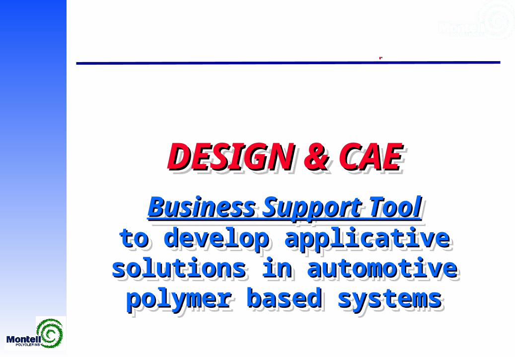
Design & CAE: a powerful tool in the Business SupportDesign & CAE: a powerful tool in the Business Support
Computer Aided EngineeringComputer Aided Engineering
Testing & validationTesting & validation
Design & CAE: a powerful tool in the Business SupportDesign & CAE: a powerful tool in the Business Support
Computer Aided EngineeringComputer Aided Engineering
Testing & validationTesting & validation
DesignDesignDesignDesign
DESIGN & CAE ACTIVITY DESIGN & CAE ACTIVITY DESIGN & CAE ACTIVITY DESIGN & CAE ACTIVITY
Montecarlo, June 7-9 2000Montecarlo, June 7-9 2000
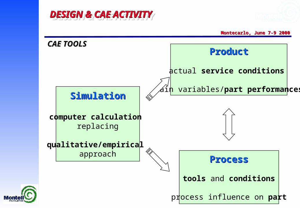
ProcessProcess
tools and conditions
process influence on part
CAE TOOLSCAE TOOLS
SimulationSimulation
computer calculation replacing
qualitative/empirical approach
ProductProduct
actual service conditions
main variables/part performances
DESIGN & CAE ACTIVITY DESIGN & CAE ACTIVITY DESIGN & CAE ACTIVITY DESIGN & CAE ACTIVITY
Montecarlo, June 7-9 2000Montecarlo, June 7-9 2000
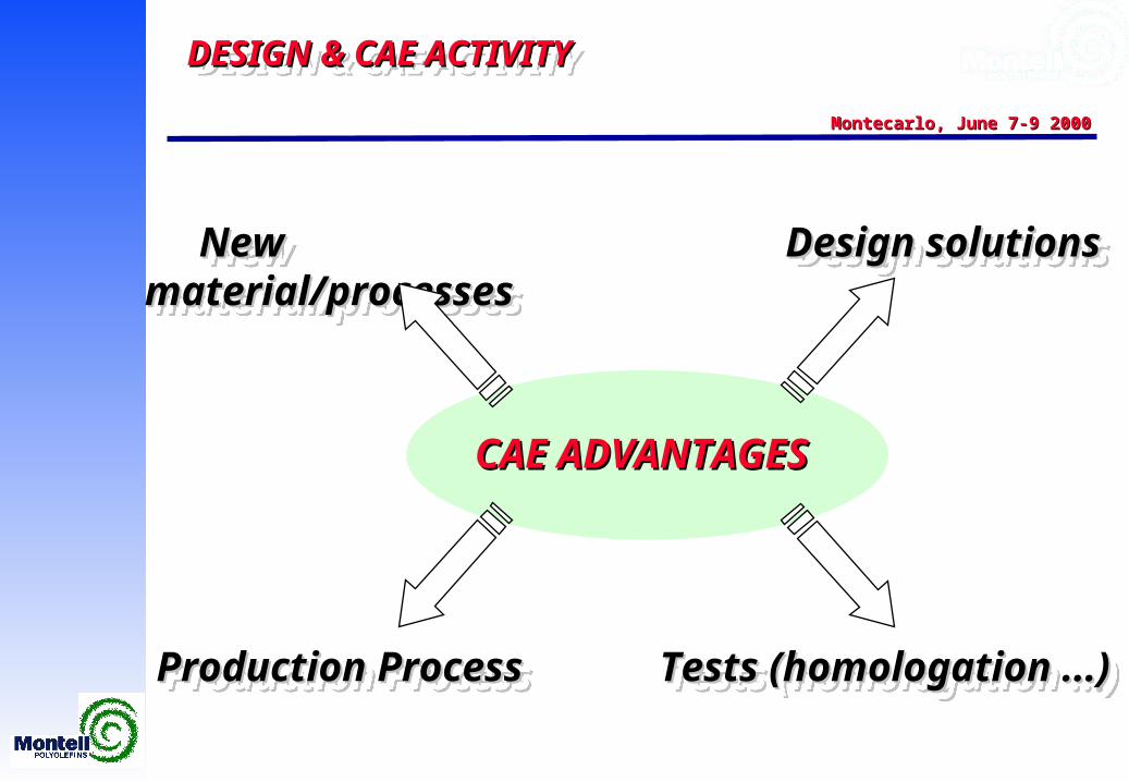
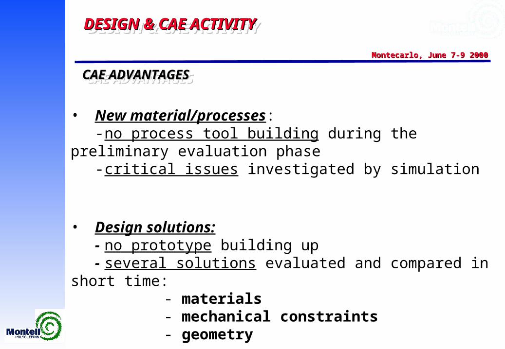
CAE ADVANTAGESCAE ADVANTAGES
New material/processesNew material/processes New material/processesNew material/processes Design solutionsDesign solutionsDesign solutionsDesign solutions
Tests (homologation ...)Tests (homologation ...)Tests (homologation ...)Tests (homologation ...)Production ProcessProduction ProcessProduction ProcessProduction Process
DESIGN & CAE ACTIVITY DESIGN & CAE ACTIVITY DESIGN & CAE ACTIVITY DESIGN & CAE ACTIVITY
Montecarlo, June 7-9 2000Montecarlo, June 7-9 2000
• New material/processes: - no process tool building during the preliminary evaluation phase
- critical issues investigated by simulation
• Design solutions: - no prototype building up
- several solutions evaluated and compared in short time:- materials- mechanical constraints- geometry
CAE ADVANTAGESCAE ADVANTAGESCAE ADVANTAGESCAE ADVANTAGES
DESIGN & CAE ACTIVITY DESIGN & CAE ACTIVITY DESIGN & CAE ACTIVITY DESIGN & CAE ACTIVITY
Montecarlo, June 7-9 2000Montecarlo, June 7-9 2000
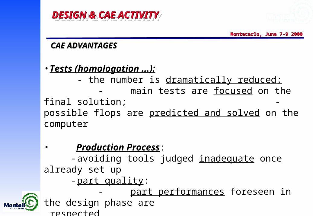
CAE ADVANTAGESCAE ADVANTAGES
• Tests (homologation ...): - the number is dramatically reduced; - main tests are focused on the final solution; - possible flops are predicted and solved on the computer
• Production Process: - avoiding tools judged inadequate once already set up
- part quality:- part performances foreseen in the design phase are
respected - controlled defects due to process
- time/costs are optimised
DESIGN & CAE ACTIVITY DESIGN & CAE ACTIVITY DESIGN & CAE ACTIVITY DESIGN & CAE ACTIVITY
Montecarlo, June 7-9 2000Montecarlo, June 7-9 2000
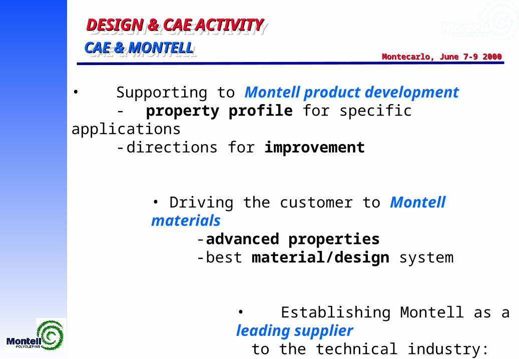
• Supporting to Montell product development - property profile for specific applications
- directions for improvement
• Driving the customer to Montell materials- advanced properties
- best material/design system
• Establishing Montell as a leading supplier to the technical industry:
- differentiated offering (product and service)
CAE & MONTELLCAE & MONTELLCAE & MONTELLCAE & MONTELL
DESIGN & CAE ACTIVITY DESIGN & CAE ACTIVITY DESIGN & CAE ACTIVITY DESIGN & CAE ACTIVITY
Montecarlo, June 7-9 2000Montecarlo, June 7-9 2000
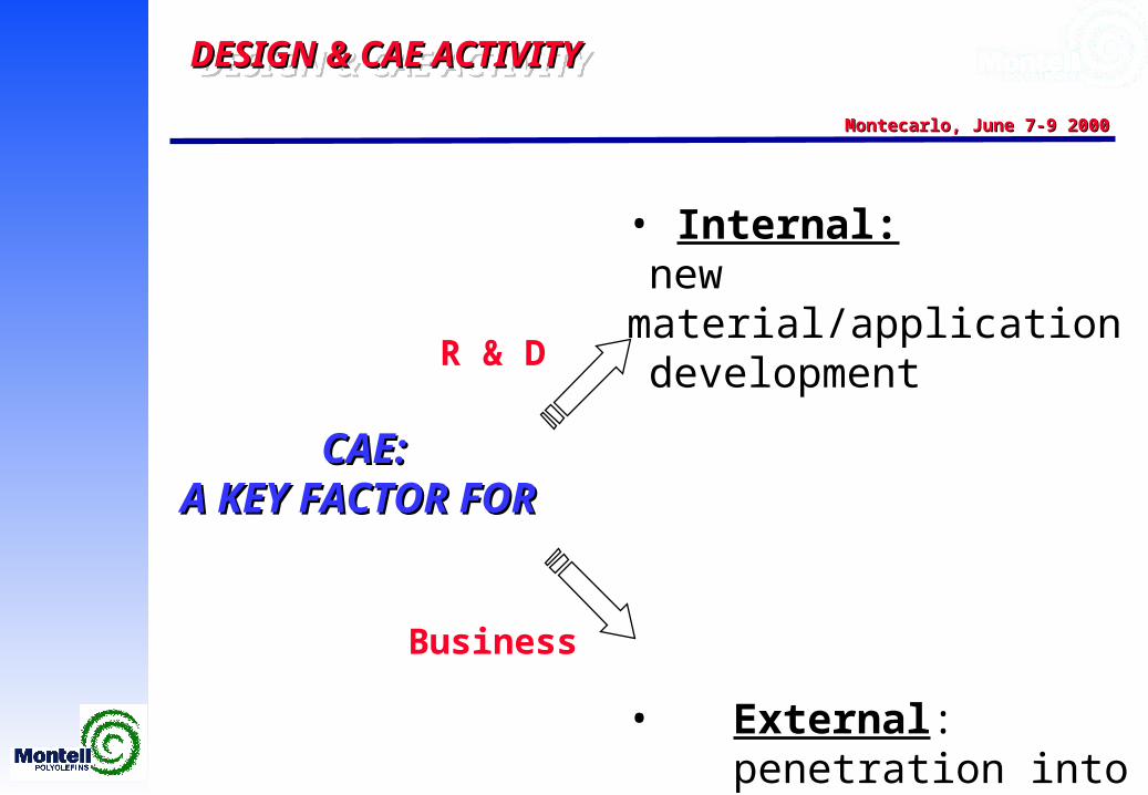
CAE:CAE:A KEY FACTOR FOR A KEY FACTOR FOR
• Internal:new material/application development
• External: penetration into the market
R & DR & D
BusinessBusiness
DESIGN & CAE ACTIVITY DESIGN & CAE ACTIVITY DESIGN & CAE ACTIVITY DESIGN & CAE ACTIVITY
Montecarlo, June 7-9 2000Montecarlo, June 7-9 2000
Car dashboards:Car dashboards:from new concepts to from new concepts to first applicative projectsfirst applicative projects
DESIGN & CAE ACTIVITY DESIGN & CAE ACTIVITY DESIGN & CAE ACTIVITY DESIGN & CAE ACTIVITY
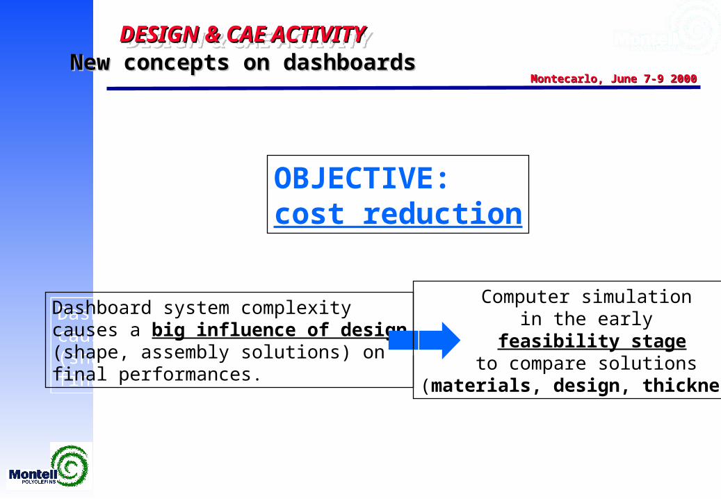
Montecarlo, June 7-9 2000Montecarlo, June 7-9 2000New concepts on dashboards New concepts on dashboards
OBJECTIVE:cost reduction
OBJECTIVE:cost reduction
Dashboard system complexitycauses a big influence of design(shape, assembly solutions) onfinal performances.
Dashboard system complexitycauses a big influence of design(shape, assembly solutions) onfinal performances.
Computer simulationin the early
feasibility stageto compare solutions
(materials, design, thickness)
Computer simulationin the early
feasibility stageto compare solutions
(materials, design, thickness)
DESIGN & CAE ACTIVITY DESIGN & CAE ACTIVITY DESIGN & CAE ACTIVITY DESIGN & CAE ACTIVITY
Montecarlo, June 7-9 2000Montecarlo, June 7-9 2000New concepts on dashboards: creep as a key issueNew concepts on dashboards: creep as a key issue
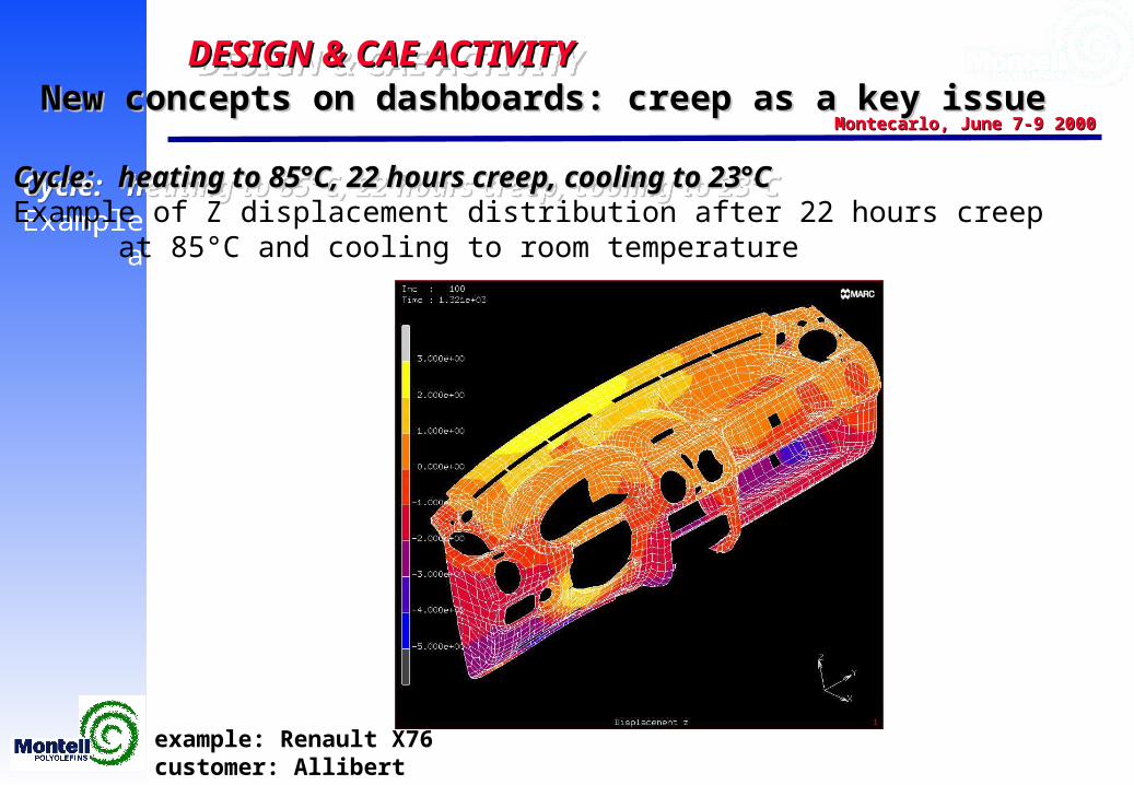
Cycle: Cycle: heating to 85°C, 22 hours creep, cooling to 23°Cheating to 85°C, 22 hours creep, cooling to 23°CExample of Z displacement distribution after 22 hours creep
at 85°C and cooling to room temperature
Cycle: Cycle: heating to 85°C, 22 hours creep, cooling to 23°Cheating to 85°C, 22 hours creep, cooling to 23°CExample of Z displacement distribution after 22 hours creep
at 85°C and cooling to room temperature
example: Renault X76customer: Allibert
DESIGN & CAE ACTIVITY DESIGN & CAE ACTIVITY DESIGN & CAE ACTIVITY DESIGN & CAE ACTIVITY
Montecarlo, June 7-9 2000Montecarlo, June 7-9 2000New concepts on dashboards: creep as a key issueNew concepts on dashboards: creep as a key issue
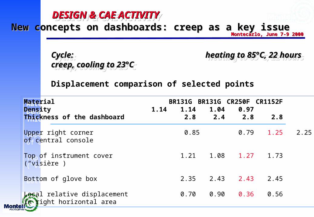
Cycle: Cycle: heating to 85°C, 22 hours creep, cooling to 23°Cheating to 85°C, 22 hours creep, cooling to 23°C
Displacement comparison of selected points
Cycle: Cycle: heating to 85°C, 22 hours creep, cooling to 23°Cheating to 85°C, 22 hours creep, cooling to 23°C
Displacement comparison of selected points
Material BR131G BR131G CR250F CR1152FDensity 1.14 1.14 1.04 0.97Thickness of the dashboard 2.8 2.4 2.8 2.8
Upper right corner 0.85 0.79 1.25 2.25of central console
Top of instrument cover 1.21 1.08 1.27 1.73(“visière”)
Bottom of glove box 2.35 2.43 2.43 2.45
Local relative displacement 0.70 0.90 0.36 0.56in right horizontal area
DESIGN & CAE ACTIVITY DESIGN & CAE ACTIVITY DESIGN & CAE ACTIVITY DESIGN & CAE ACTIVITY
Montecarlo, June 7-9 2000Montecarlo, June 7-9 2000
STRATEGY:STRATEGY:concurrent engineering andconcurrent engineering andsimulation based design offered simulation based design offered to selected partnersto selected partners
STRATEGY:STRATEGY:concurrent engineering andconcurrent engineering andsimulation based design offered simulation based design offered to selected partnersto selected partners
DESIGN & CAE ACTIVITY DESIGN & CAE ACTIVITY DESIGN & CAE ACTIVITY DESIGN & CAE ACTIVITY
Montecarlo, June 7-9 2000Montecarlo, June 7-9 2000
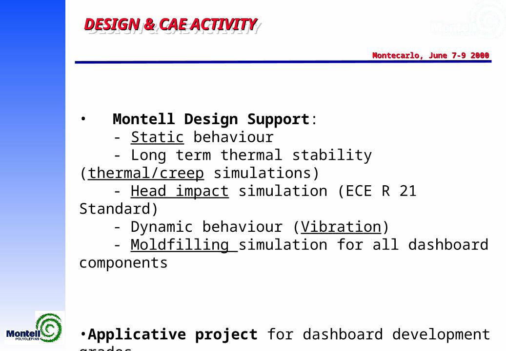
• Montell Design Support:- Static behaviour- Long term thermal stability (thermal/creep simulations)- Head impact simulation (ECE R 21 Standard)- Dynamic behaviour (Vibration)- Moldfilling simulation for all dashboard components
•Applicative project for dashboard development grades
• Montell Design Support:- Static behaviour- Long term thermal stability (thermal/creep simulations)- Head impact simulation (ECE R 21 Standard)- Dynamic behaviour (Vibration)- Moldfilling simulation for all dashboard components
•Applicative project for dashboard development grades
DESIGN & CAE ACTIVITY DESIGN & CAE ACTIVITY DESIGN & CAE ACTIVITY DESIGN & CAE ACTIVITY
Montecarlo, June 7-9 2000Montecarlo, June 7-9 2000
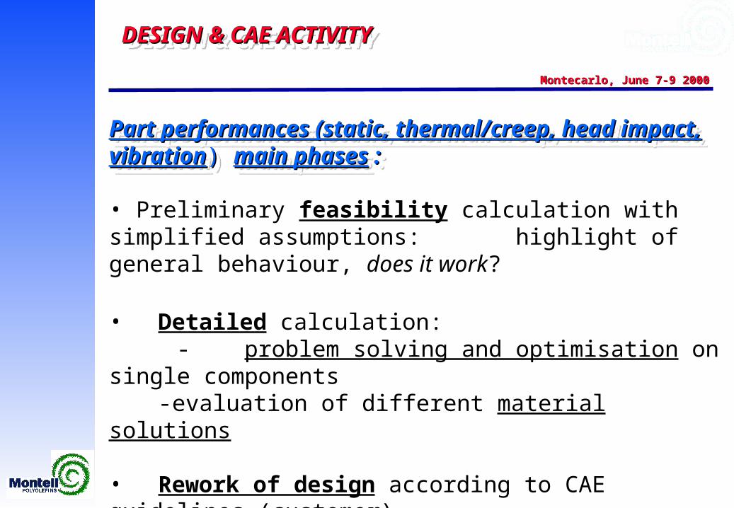
Part performances (static, thermal/creep, head impact, vibrationPart performances (static, thermal/creep, head impact, vibration) ) main phasesmain phases : :
• Preliminary feasibility calculation with simplified assumptions:highlight of general behaviour, does it work?
• Detailed calculation: - problem solving and optimisation on single components - evaluation of different material solutions
• Rework of design according to CAE guidelines (customer)
• Possible last calculation on final design
DESIGN & CAE ACTIVITY DESIGN & CAE ACTIVITY DESIGN & CAE ACTIVITY DESIGN & CAE ACTIVITY
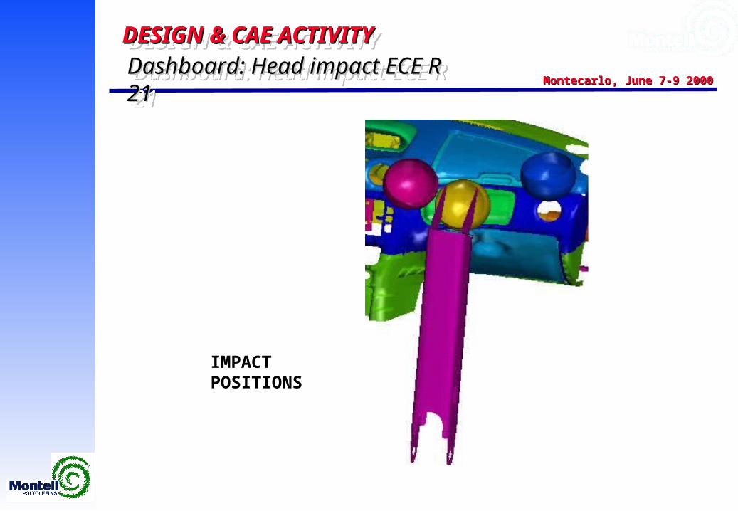
Montecarlo, June 7-9 2000Montecarlo, June 7-9 2000Dashboard: Head impact ECE R 21Dashboard: Head impact ECE R 21Dashboard: Head impact ECE R 21Dashboard: Head impact ECE R 21
IMPACT POSITIONS
IMPACT POSITIONS
DESIGN & CAE ACTIVITY DESIGN & CAE ACTIVITY DESIGN & CAE ACTIVITY DESIGN & CAE ACTIVITY
Montecarlo, June 7-9 2000Montecarlo, June 7-9 2000
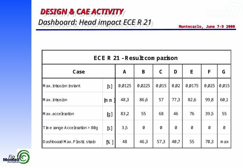
A B C D E F G
Max. intrusion instant [s] 0,0125 0,0225 0,015 0,02 0,0175 0,025 0,015
Max. intrusion [mm] 48,3 86,6 57 77,3 82,6 99,8 60,1
Max. acceleration [g] 83,2 55 68 46 76 39,5 55
Time range Acceleration > 80g [s] 3,5 0 0 0 0 0 0
Dashboard Max. Plastic strain [%] 48 46,3 57,3 40,7 55 70,3 max
ECE R 21 - Result comparison
Case
Fig 18
Dashboard: Head impact ECE R 21Dashboard: Head impact ECE R 21Dashboard: Head impact ECE R 21Dashboard: Head impact ECE R 21
DESIGN & CAE ACTIVITY DESIGN & CAE ACTIVITY DESIGN & CAE ACTIVITY DESIGN & CAE ACTIVITY
Montecarlo, June 7-9 2000Montecarlo, June 7-9 2000
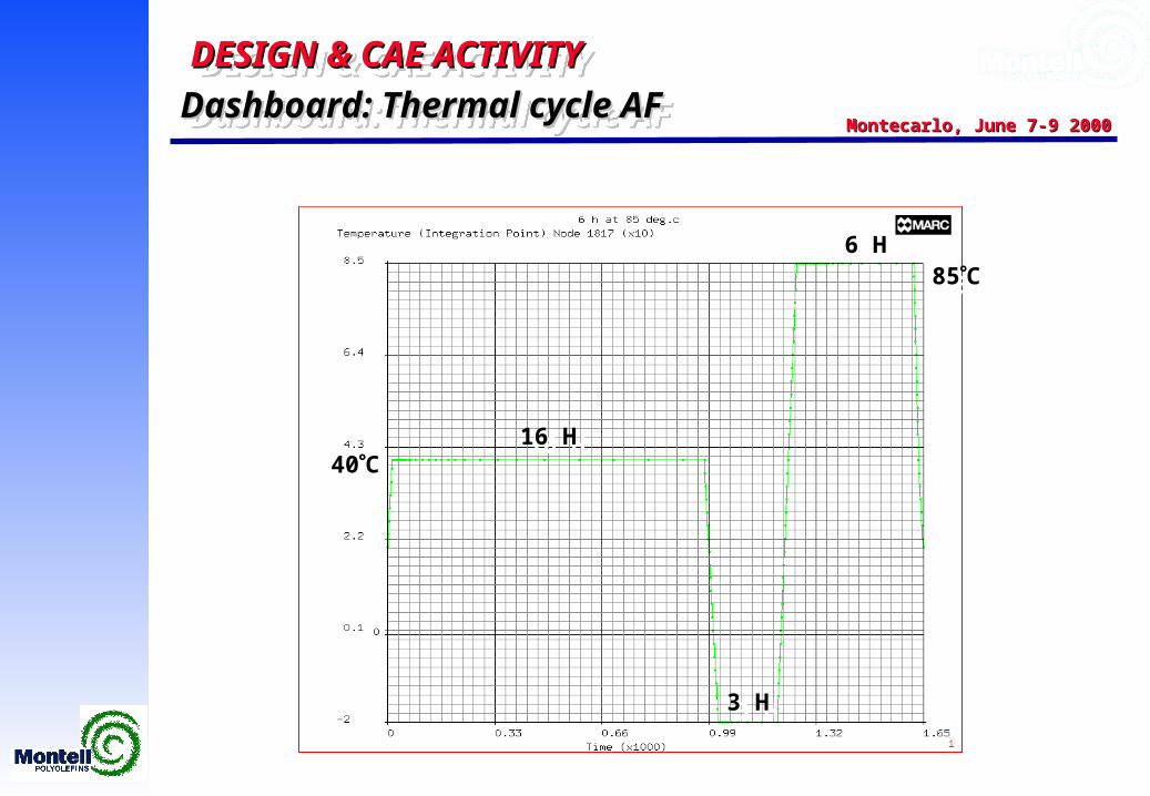
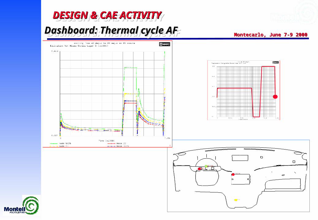
40C40C
85C85C
16 H16 H
3 H3 H
6 H6 H
Dashboard: Thermal cycle AFDashboard: Thermal cycle AFDashboard: Thermal cycle AFDashboard: Thermal cycle AF
DESIGN & CAE ACTIVITY DESIGN & CAE ACTIVITY DESIGN & CAE ACTIVITY DESIGN & CAE ACTIVITY
Montecarlo, June 7-9 2000Montecarlo, June 7-9 2000
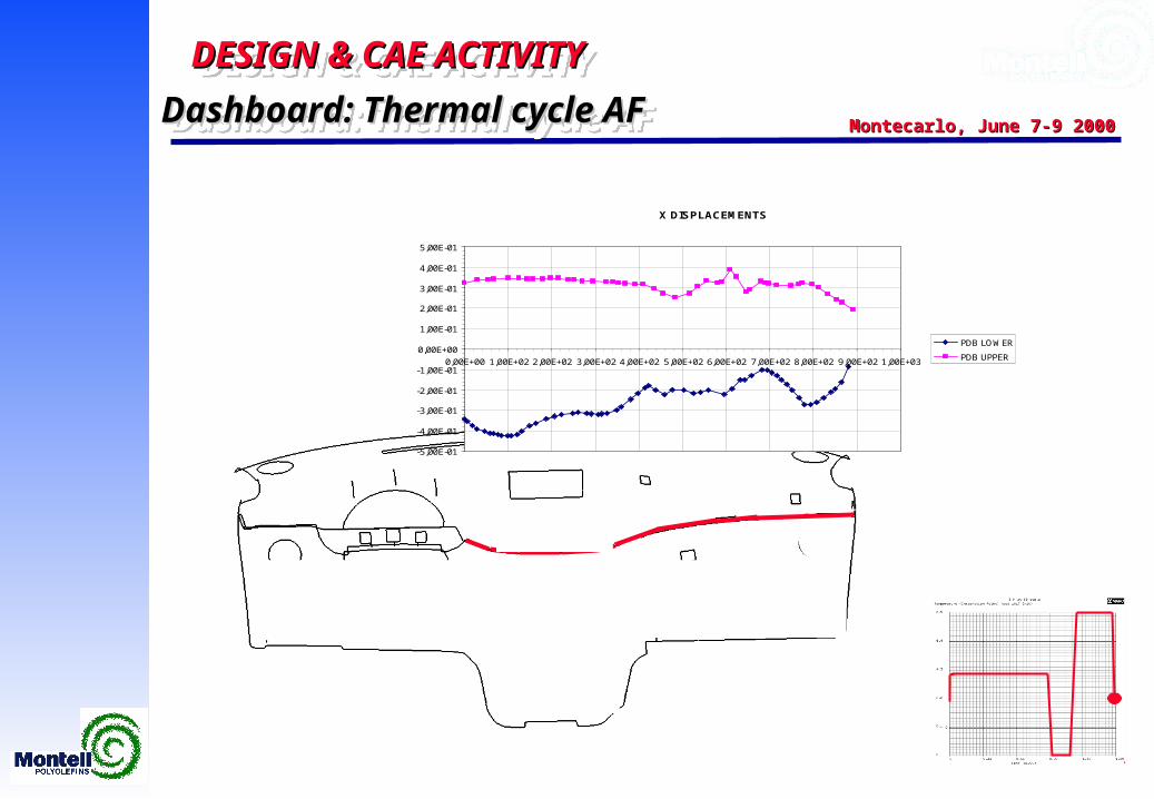
Dashboard: Thermal cycle AFDashboard: Thermal cycle AFDashboard: Thermal cycle AFDashboard: Thermal cycle AF
DESIGN & CAE ACTIVITY DESIGN & CAE ACTIVITY DESIGN & CAE ACTIVITY DESIGN & CAE ACTIVITY
Montecarlo, June 7-9 2000Montecarlo, June 7-9 2000
X DISPLACEMENTS
-5,00E-01
-4,00E-01
-3,00E-01
-2,00E-01
-1,00E-01
0,00E+00
1,00E-01
2,00E-01
3,00E-01
4,00E-01
5,00E-01
0,00E+00 1,00E+02 2,00E+02 3,00E+02 4,00E+02 5,00E+02 6,00E+02 7,00E+02 8,00E+02 9,00E+02 1,00E+03
PDB LOWER
PDB UPPER
Dashboard: Thermal cycle AFDashboard: Thermal cycle AFDashboard: Thermal cycle AFDashboard: Thermal cycle AF
DESIGN & CAE ACTIVITY DESIGN & CAE ACTIVITY DESIGN & CAE ACTIVITY DESIGN & CAE ACTIVITY
Montecarlo, June 7-9 2000Montecarlo, June 7-9 2000
Dashboard Component:Dashboard Component:Manufacturing process designManufacturing process designDashboard Component:Dashboard Component:Manufacturing process designManufacturing process design
DESIGN & CAE ACTIVITY DESIGN & CAE ACTIVITY DESIGN & CAE ACTIVITY DESIGN & CAE ACTIVITY
Montecarlo, June 7-9 2000Montecarlo, June 7-9 2000Dashboard : Manufacturing process designDashboard : Manufacturing process design
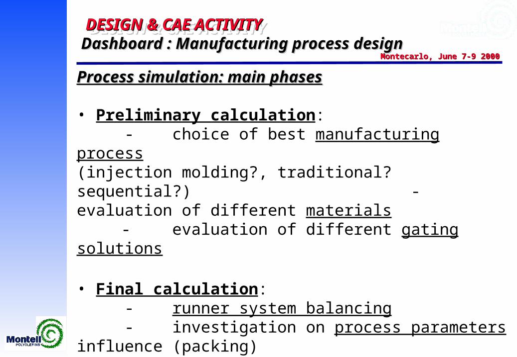
Process simulation: main phasesProcess simulation: main phases
• Preliminary calculation: - choice of best manufacturing process
(injection molding?, traditional? sequential?)- evaluation of different materials- evaluation of different gating solutions
• Final calculation: - runner system balancing- investigation on process parameters influence (packing)
• Special calculations for critical parts (injection molding):- cooling- warpage
DESIGN & CAE ACTIVITY DESIGN & CAE ACTIVITY DESIGN & CAE ACTIVITY DESIGN & CAE ACTIVITY
Montecarlo, June 7-9 2000Montecarlo, June 7-9 2000
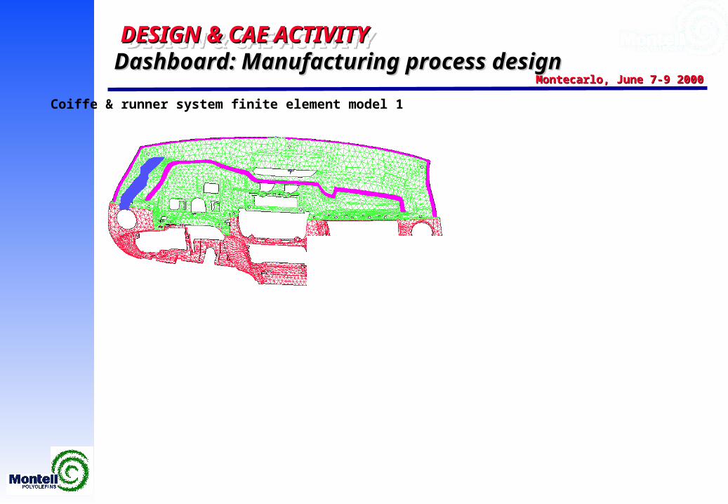
Coiffe & runner system finite element model 1
Dashboard: Manufacturing process designDashboard: Manufacturing process design
DESIGN & CAE ACTIVITY DESIGN & CAE ACTIVITY DESIGN & CAE ACTIVITY DESIGN & CAE ACTIVITY
Montecarlo, June 7-9 2000Montecarlo, June 7-9 2000
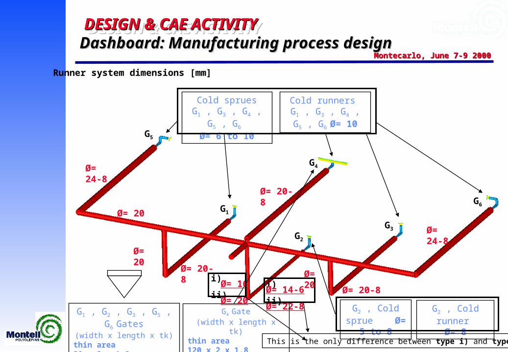
Runner system dimensions [mm]
Cold spruesG1 , G3 , G4 , G5 , G6
Ø= 6 to 10
G1
G2
G4
G5
G3
Ø= 20-8
i) Ø= 14-6ii) Ø= 22-8
Ø= 24-8
Ø= 20-8
Ø= 20
Cold runners G1 , G3 , G4 , G5 , G6
Ø= 10
G1 , G2 , G3 , G5 , G6 Gates(width x length x tk)
thin area 20 x 2 x 1.8thick area 20-0 x 8 x 8
G6
Ø= 20
Ø= 20
Ø= 24-8
Ø= 20-8
G2 , Cold sprue Ø= 5 to 8
G2 , Cold runner Ø= 8
G4 Gate(width x length x tk)
thin area 120 x 2 x 1.8thick area 120 x 8 x 8
i) Ø= 16ii) Ø= 20
This is the only difference between type i) and type ii)
Dashboard: Manufacturing process designDashboard: Manufacturing process design
DESIGN & CAE ACTIVITY DESIGN & CAE ACTIVITY DESIGN & CAE ACTIVITY DESIGN & CAE ACTIVITY
Montecarlo, June 7-9 2000Montecarlo, June 7-9 2000
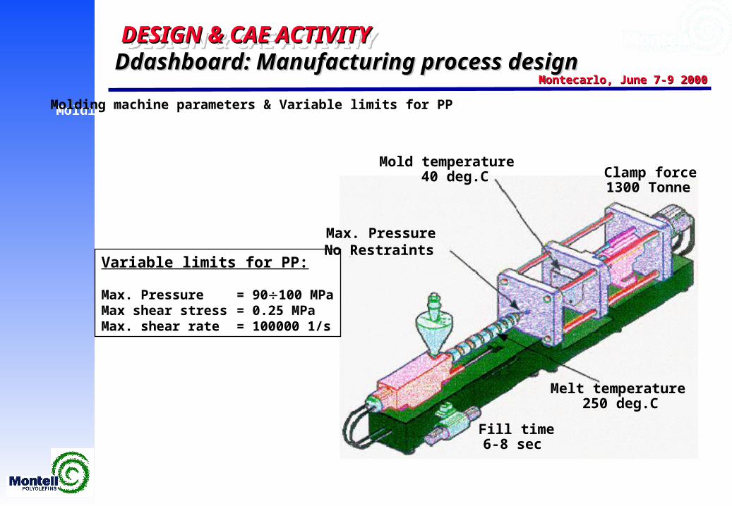
Fill time6-8 sec
Melt temperature250 deg.C
Mold temperature 40 deg.C
No Restraints
Clamp force1300 Tonne
Max. Pressure
Molding machine parameters & Variable limits for PPMolding machine parameters & Variable limits for PP
Variable limits for PP:
Max. Pressure = 90100 MPaMax shear stress = 0.25 MPaMax. shear rate = 100000 1/s
Ddashboard: Manufacturing process designDdashboard: Manufacturing process design
DESIGN & CAE ACTIVITY DESIGN & CAE ACTIVITY DESIGN & CAE ACTIVITY DESIGN & CAE ACTIVITY
Montecarlo, June 7-9 2000Montecarlo, June 7-9 2000
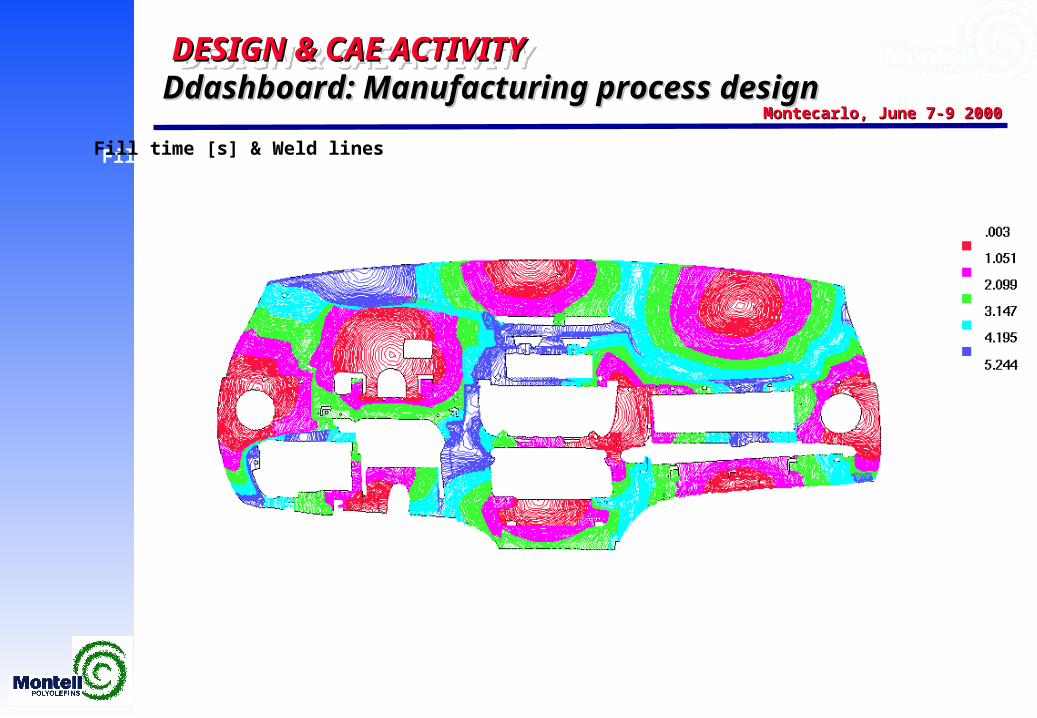
Fill time [s] & Weld linesFill time [s] & Weld lines
Ddashboard: Manufacturing process designDdashboard: Manufacturing process design
DESIGN & CAE ACTIVITY DESIGN & CAE ACTIVITY DESIGN & CAE ACTIVITY DESIGN & CAE ACTIVITY
Montecarlo, June 7-9 2000Montecarlo, June 7-9 2000
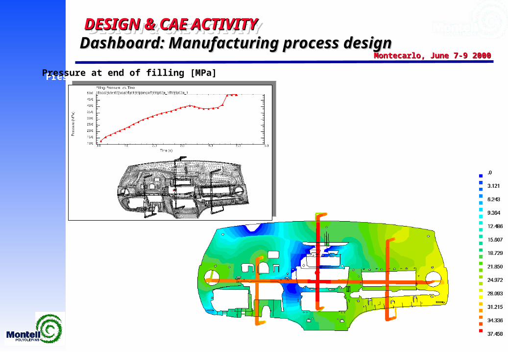
Pressure at end of filling [MPa]Pressure at end of filling [MPa]
Dashboard: Manufacturing process designDashboard: Manufacturing process design
DESIGN & CAE ACTIVITY DESIGN & CAE ACTIVITY DESIGN & CAE ACTIVITY DESIGN & CAE ACTIVITY
Montecarlo, June 7-9 2000Montecarlo, June 7-9 2000
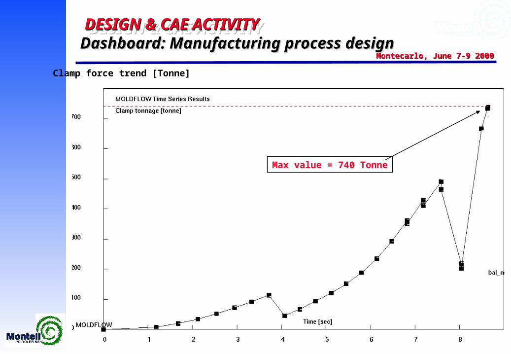
Clamp force trend [Tonne]
Max value = 740 Tonne
Dashboard: Manufacturing process designDashboard: Manufacturing process design
DESIGN & CAE ACTIVITY DESIGN & CAE ACTIVITY DESIGN & CAE ACTIVITY DESIGN & CAE ACTIVITY
Montecarlo, June 7-9 2000Montecarlo, June 7-9 2000
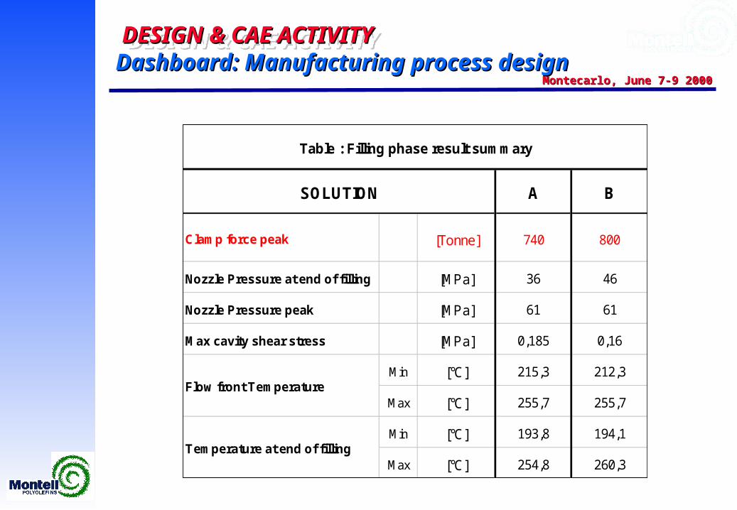
A B
Clamp force peak [Tonne] 740 800
Nozzle Pressure at end of filling [MPa] 36 46
Nozzle Pressure peak [MPa] 61 61
Max cavity shear stress [MPa] 0,185 0,16
Min [°C] 215,3 212,3
Max [°C] 255,7 255,7
Min [°C] 193,8 194,1
Max [°C] 254,8 260,3
SOLUTION
Flow front Temperature
Temperature at end of filling
Table : Filling phase result summary
Dashboard: Manufacturing process designDashboard: Manufacturing process design
DESIGN & CAE ACTIVITY DESIGN & CAE ACTIVITY DESIGN & CAE ACTIVITY DESIGN & CAE ACTIVITY
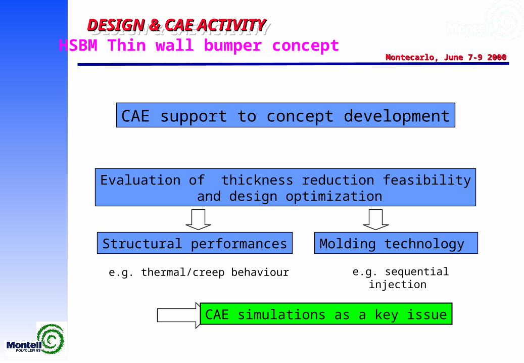
Montecarlo, June 7-9 2000Montecarlo, June 7-9 2000HSBM Thin wall bumper concept
CAE support to concept developmentCAE support to concept development
Structural performancesStructural performances Molding technology Molding technology
Evaluation of thickness reduction feasibility and design optimization
Evaluation of thickness reduction feasibility and design optimization
e.g. thermal/creep behaviour e.g. thermal/creep behaviour e.g. sequential injection e.g. sequential injection
CAE simulations as a key issueCAE simulations as a key issue
DESIGN & CAE ACTIVITY DESIGN & CAE ACTIVITY DESIGN & CAE ACTIVITY DESIGN & CAE ACTIVITY
Montecarlo, June 7-9 2000Montecarlo, June 7-9 2000Thermal/creep cycle simulation on bumpersThermal/creep cycle simulation on bumpersThermal/creep cycle simulation on bumpersThermal/creep cycle simulation on bumpers
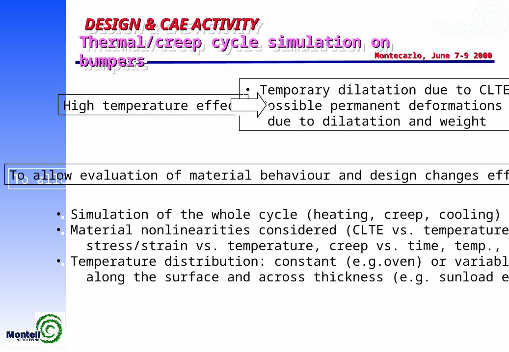
High temperature effect• Temporary dilatation due to CLTE• Possible permanent deformations due to dilatation and weight
• Temporary dilatation due to CLTE• Possible permanent deformations due to dilatation and weight
To allow evaluation of material behaviour and design changes effect:To allow evaluation of material behaviour and design changes effect:
• Simulation of the whole cycle (heating, creep, cooling)• Material nonlinearities considered (CLTE vs. temperature, stress/strain vs. temperature, creep vs. time, temp., stress)• Temperature distribution: constant (e.g.oven) or variable along the surface and across thickness (e.g. sunload effect)
• Simulation of the whole cycle (heating, creep, cooling)• Material nonlinearities considered (CLTE vs. temperature, stress/strain vs. temperature, creep vs. time, temp., stress)• Temperature distribution: constant (e.g.oven) or variable along the surface and across thickness (e.g. sunload effect)
DESIGN & CAE ACTIVITY DESIGN & CAE ACTIVITY DESIGN & CAE ACTIVITY DESIGN & CAE ACTIVITY
Montecarlo, June 7-9 2000Montecarlo, June 7-9 2000Thermal/creep cycle simulation on bumpersThermal/creep cycle simulation on bumpersThermal/creep cycle simulation on bumpersThermal/creep cycle simulation on bumpers
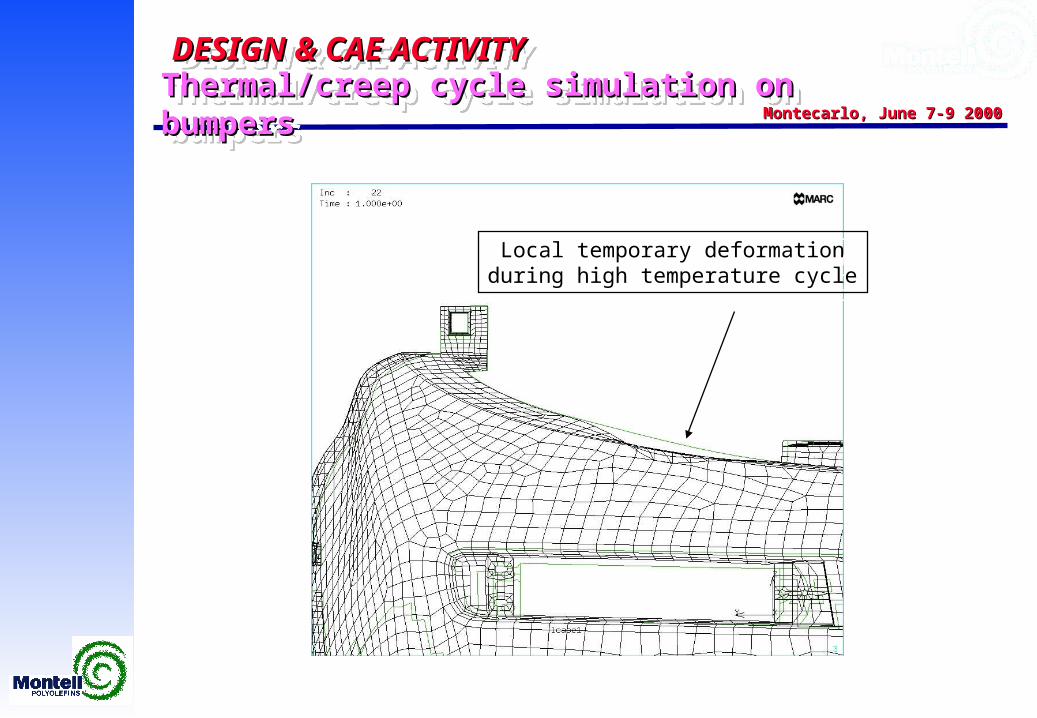
Local temporary deformationduring high temperature cycle
Local temporary deformationduring high temperature cycle
DESIGN & CAE ACTIVITY DESIGN & CAE ACTIVITY DESIGN & CAE ACTIVITY DESIGN & CAE ACTIVITY
Montecarlo, June 7-9 2000Montecarlo, June 7-9 2000Thermal/creep cycle simulation on bumpersThermal/creep cycle simulation on bumpersThermal/creep cycle simulation on bumpersThermal/creep cycle simulation on bumpers
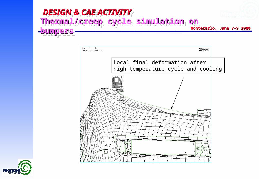
Local final deformation afterhigh temperature cycle and cooling
Local final deformation afterhigh temperature cycle and cooling
DESIGN & CAE ACTIVITY DESIGN & CAE ACTIVITY DESIGN & CAE ACTIVITY DESIGN & CAE ACTIVITY
Montecarlo, June 7-9 2000Montecarlo, June 7-9 2000
!
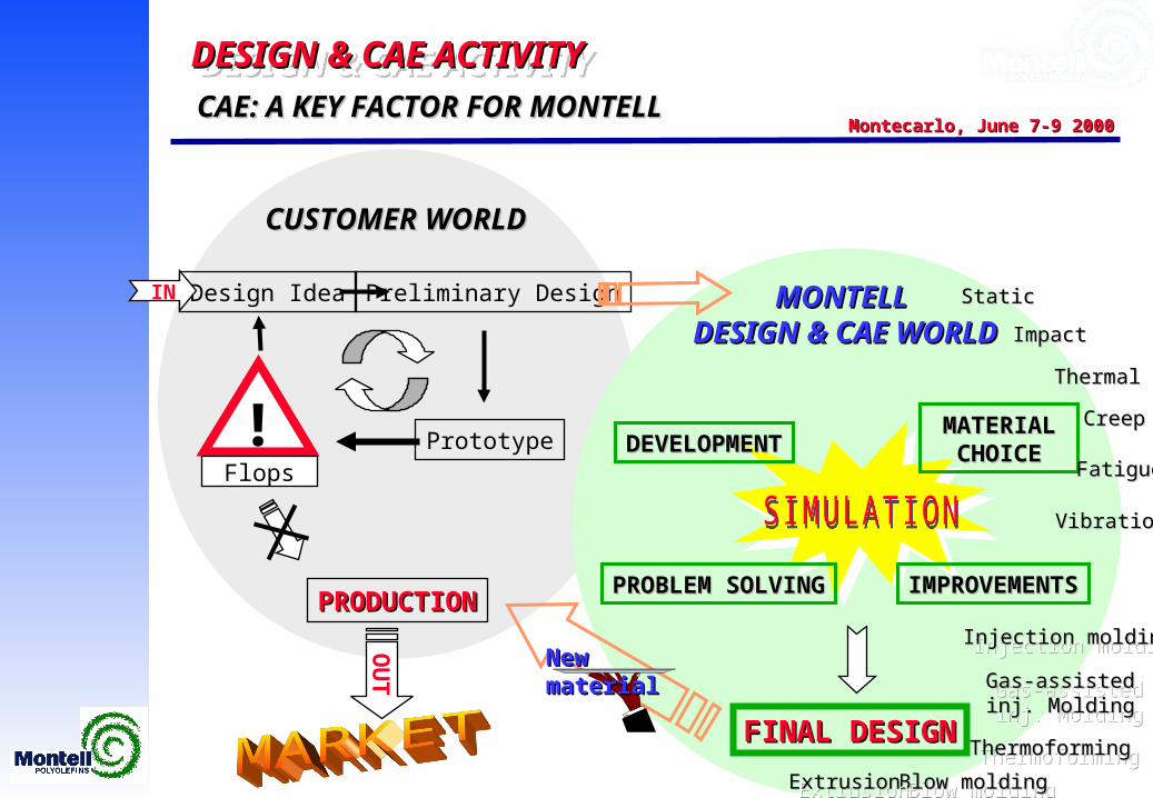
CAE: A KEY FACTOR FOR MONTELL CAE: A KEY FACTOR FOR MONTELL
Design Idea Preliminary Design
PrototypeFlops
PRODUCTIONPRODUCTION
IN
CUSTOMER WORLDCUSTOMER WORLD
FINAL DESIGNFINAL DESIGN
MONTELL MONTELL DESIGN & CAE WORLDDESIGN & CAE WORLD
OU
T
IMPROVEMENTSIMPROVEMENTSPROBLEM SOLVINGPROBLEM SOLVING
DEVELOPMENTDEVELOPMENTMATERIAL MATERIAL
CHOICECHOICE
StaticStatic
ImpactImpact
ThermalThermal
CreepCreep
FatigueFatigue
VibrationVibration
Injection moldingInjection moldingInjection moldingInjection molding
Gas-assisted Gas-assisted inj. Moldinginj. Molding
Gas-assisted Gas-assisted inj. Moldinginj. Molding
ThermoformingThermoformingThermoformingThermoforming
Blow moldingBlow moldingBlow moldingBlow moldingExtrusionExtrusionExtrusionExtrusion
New materialNew material