Embed Size (px)
Citation preview

Design, Construction & Maintenance of WSUD


Contents
Executive summary 4
1. Introduction 6
1.1 Background 7 1.2 Purpose of the Guidelines 7 1.3 How to use the Guidelines 7 1.4 What is Water Sensitive Urban Design? 7 1.5 Why use Water Sensitive Urban Design? 7 1.6 Regulatory considerations for stormwater management 8 1.6.1 State Environment Protection Policy (Waters of Victoria) 8 1.6.2 Victoria Planning Provisions 8 1.7 Urban Stormwater Best Practice Environmental Management Guidelines
for stormwater treatments 9
2. WSUD and Council Approval Process 10
2.1 Step 1: Pre-Application Consultation 11
2.1.1 Approved WSUD treatment types 12 2.1.2 Construction and defect liability requirements, design and maintenance considerations 12 2.1.3 Subdivisions within Melbourne Water Development Services Schemes 12 2.1.4 Sites of less than 1ha 12
2.2 Step 2: Submission of Conceptual Design 12
2.2.1 Report on WSUD Design Intent 13 2.2.2 Construction phase requirements 14 2.2.3 Maintenance, handover and defect liability period 14
2.3 Step 3: Submission of Detailed Design 15
3. References 16
4. Acknowledgements 17
List of appendices
Appendix A: WSUD Treatment Function, Applicability and Maintenance Considerations 18Appendix B: WSUD Treatment Measures – Design and Maintenance Considerations 21
List of tables
Table A-1: Summary of treatment function, applicability and cost 19Table A-2: Indicative ongoing maintenance requirements 20
List of figures
Figure 1: Approval process for permit applications for developments including WSUD 11
List of photos
Figure B-1: Bioretention Swale 23Figure B-2: Bioretention Basin 24Figure B-3: Vegetated Swale 25Figure B-4: Underground Sand Filter 26Figure B-5: Sedimentation Basin 27Figure B-6: Constructed wetland macrophyte zone 28Figure B-7: Pond system with edge vegetation 29Figure B-8: Slim line rainwater tank 30 Figure B-9: Royal Park 31 Figure B-10: Stormwater harvesting tank 31

Executive Summary
Water Sensitive Urban Design Guidelines4
These Water Sensitive Urban Design (WSUD) Guidelines set out Council’s expectations for WSUD projects within the municipality, to inform developers and consultants. The document provides information on the approvals process, design considerations, suitability of WSUD types in different conditions and considerations for construction, protection, maintenance and handover of WSUD assets. These guidelines should be used in conjunction with the published manuals that outline the WSUD design requirements (refer to references section and the council specific addenda).
In addition to the usual requirements for planning applications, the following items should be considered for applications including WSUD:
• Approval Process (Section 2)
1. Pre-application consultation between applicant, Council and other relevant stakeholders (such as Melbourne Water), to discuss proposed compliance with Council-specific WSUD requirements.
2. Submission of conceptual design of WSUD treatments with planning application, including report on WSUD design intent, confirming how compliance with Council-specific requirements will be achieved.
3. Submission of detailed design of WSUD treatments for construction purposes, provided after the Planning Permit is issued and prior to works commencing. Matters for attention include specific Planning Permit conditions, where applicable, and design compliance with Council-specific standard requirements such as.
• Council-specific requirements listed in the Addendum to these Guidelines (this includes approved WSUD treatment types and information on the drainage authority, local drainage schemes and requirements for sites of less than 1 ha).
• Construction phase requirements to ensure effectiveness of WSUD treatment systems at time of installation and protection until handover (Section 2.2.2).
• Maintenance, handover and defects liability requirements (Section 2.2.3).
• WSUD treatment system design and maintenance considerations (Appendices A and B).
5

1. Introduction
Water Sensitive Urban Design Guidelines6

1.1 BackgroundIn 2009, Melbourne Water’s Living Rivers Stormwater Program provided funding to progress and finalise Water Sensitive Urban Design (WSUD) Guidelines for councils on the northern and western fringe of Melbourne. To assist Melbourne Water, Parsons Brinkerhoff were commissioned to develop these guidelines and relevant council specific addenda for the Hume, Whittlesea and Wyndham City Councils, and the Macedon Ranges, Melton, Mitchell and Moorabool Shire Councils.
1.2 Purpose of the GuidelinesThese guidelines aim to set out Council’s expectations for WSUD projects within their municipality, to inform developers and consultants. The document provides information on the approvals process, design considerations, suitability of WSUD types in different conditions and considerations for construction, protection, maintenance and handover of WSUD assets.
The WSUD Guidelines do not seek to recreate the good technical guidance provided in other published documents (see the References section), but rather to tie these documents together and act as a first reference point for WSUD projects. The guidelines also seek to provide greater consistency in WSUD requirements between Councils..
1.3 How to use the GuidelinesThis document aims to provide greater consistency in Council requirements for developments incorporating WSUD techniques across Council boundaries. Hence the main document and Appendices A and B should remain consistent across the region, while the Addendum contains the Council-specific requirements. These guidelines should be used in conjunction with the existing planning framework and are applicable to various types of developments including residential, commercial and industrial developments.
1.4 What is Water Sensitive Urban Design?Water Sensitive Urban Design integrates urban water cycle management with urban planning and design, with the aim of mimicking natural systems to minimise negative impacts on the natural water cycle and receiving waterways and bays. It offers an alternative to the traditional conveyance approach to stormwater management by acting at the development scale (at the source), and thereby reducing the required size of the structural stormwater system. It seeks to minimise impervious surfaces, reuse water on site, incorporate detention and retention basins to reduce peak flows, and incorporate biofiltration systems to remove pollutants.
The key principles of WSUD as stated in the Urban Stormwater: Best Practice Environmental Management Guidelines (BPEMG) (Victorian Stormwater Committee, 1999) are:
a. Protect and enhance natural water systems within urban environments.
b. Integrate stormwater treatment into the landscape, maximising the visual and recreational amenity of developments.
c. Improve the quality of water draining from urban developments into receiving environments.
d. Reduce runoff and peak flows from urban developments by increasing local detention times and minimising impervious areas.
e. Minimise drainage infrastructure costs of development due to reduced runoff and peak flows.
1.5 Why use Water Sensitive Urban Design?Stormwater is the water that runs off our urban surfaces following rain events. It has been identified as a key cause of pollution and declining health of our waterways.
As urban development occurs, the proportion of impervious surfaces in our catchments increases. This increases the velocity and amount of water running into our waterways, creating problems of erosion and flooding and changing natural flow regimes, with associated ecological damage. It also washes more pollutants into our streams, further impacting upon river health.
WSUD has been identified as a means to control flows and filter stormwater to remove pollutants. It offers the potential to reduce the costs, infrastructure sizing and occupied land area associated with conventional drainage approaches whilst treating runoff closer to its source. This more effectively mimics a natural system and, as treatment can be located further upstream than for conventional approaches, is efficient by providing flow-down effects that benefit the entire catchment.
The benefits of WSUD are such that the approach is now supported – and in some cases mandated – by various regulations and policies applied across Victoria. These are briefly outlined in the following section..
7

Water Sensitive Urban Design Guidelines8
1.6 Regulatory considerations for stormwater management
1.6.1 State Environment Protection Policy (Waters of Victoria)
The State Environment Protection Policy (SEPP) (Waters of Victoria) (EPA Victoria, 2003) is a state wide policy requiring that runoff from urban and rural areas must not compromise the beneficial uses of receiving waterways. This policy specifically refers to stormwater pollution and requires the implementation of measures to control its environmental impact. WSUD is a tool used to comply with this Policy.
1.6.2 Victoria Planning Provisions
The Victoria Planning Provisions (VPP) contain a number of clauses that support the sustainable management of stormwater runoff from development, including the use of WSUD. These include the State Planning Policy Framework Clauses 11, 12, 14, 15 and 18.09, which pertain to all types of development within the state. Councils are responsible for administering planning policies, and these clauses provide a solid basis in the planning scheme for Councils to apply WSUD requirements to all developments, including residential, industrial and commercial uses.
Furthermore, Clauses 56.07 and 56.08 of the VPP were introduced on 9 October 2006, and have provided a significant driver for the development of these guidelines. Clause 56.07 relates to integrated water management in residential subdivisions, and Clause 56.07-4 and Standard C25 mandate best practice targets for pollutant load reductions and flow discharges to be met in such developments. In most cases, this will necessitate the incorporation of WSUD into the subdivision design. Clause 56.08 establishes requirements for site management during residential subdivision works and includes many issues pertinent to the protection of WSUD systems, such as site sediment control.
This document is designed to guide the integration of WSUD into all types of developments, including residential, industrial and commercial. It does, in particular, also aim to set out and simplify the process and requirements involved in satisfying Clause 56.07-4.
All of the abovementioned planning policies relating to stormwater management apply state wide. Further information on these policies is provided below.
Clause 11 – Introduction, goal and principles
This Clause, and the following Clauses, establishes the link between the planning system and the state requirements for environmental protection and provides guidance for developers from a planning perspective.
Clause 12 – Metropolitan development
Clause 12 applies to development within metropolitan Melbourne. The strategy for stormwater management, under 12.07-2, is to “Reduce the impact of stormwater on bays and catchments” by:
• Incorporating water-sensitive urban design techniques into developments to: – Protect and enhance natural water systems. – Integrate stormwater treatment into the landscape. – Protect quality of water. – Reduce run-off and peak flows. – Minimise drainage and infrastructure costs.
Clause 14 – Settlement
Clause 14 aims to ensure a sufficient amount of land is available for residential, commercial, industrial, recreational, institutional and other public uses within urban areas. It requires that the decision making by planning and responsible authorities ‘must’ be consistent with relevant requirements of the State Environment Protection Policies including Waters of Victoria and any specific catchment policies.
Clause 15 – Environment
Clause 15 aims to assist the protection, and where possible, restoration of catchments, waterways, water bodies, groundwater and marine environment. It states that “Planning and responsible authorities should ensure land use and development proposals minimise nutrient contributions to waterways … consistent with … the Urban Stormwater: Best Practice Environmental Management Guidelines (Victorian Stormwater Committee 1999)”. Refer to Section 1.7 for more information.

9
Clause 18 – Infrastructure
Clause 18 aims to integrate land use and transport planning around existing and planned declared highways (roads), railways, principle bus routes and tram lines.
Clause 18.09, water supply, sewerage and drainage, requires that planning and responsible authorities should ensure that:
a. Water quality in water supply catchments is protected from possible contamination by urban, industrial and agricultural land uses.
b. Best environmental management practice is used where practicable in the design and management of urban stormwater drainage systems, including measures to reduce peak flows and assist screening, filtering and treatment of stormwater, to enhance flood protection and minimise impacts on water quality in receiving waters.
Clause 56.07-4 and Standard C25
Under Clause 56.07-4 local Councils are responsible for requiring that urban runoff from new residential subdivisions of 2 lots or more meet best practice water quality and flow requirements. The objectives of Clause 56.07-4, which must be met, are:
a. To minimise damage to properties and inconvenience to residents from urban run-off.
b. To ensure that the street operates adequately during major storm events and provides for public safety.
c. To minimise increases in stormwater run-off and protect the environmental values and physical characteristics of receiving waters from degradation by urban run-off.
Standard C25 sets out the normal way of meeting the Clause 56.07-4 objectives. Among other requirements, Standard C25 requires that urban stormwater management systems ‘must’ be:
a. Designed to meet current best practice performance objectives for stormwater quality, as outlined in the Urban Stormwater: Best Practice Environmental Management Guidelines (Victorian Stormwater Committee 1999) as amended. Refer to Section 1.7 for more information.
b. Designed to ensure that flows downstream of the subdivision site are restricted to predevelopment levels unless increased flows are approved by the relevant drainage authority and there are no detrimental downstream impacts.
Standard C25 requires that urban stormwater management systems must be designed and managed to the requirements of the relevant drainage authority. This is typically Council, with the exception of catchments of 60ha or more within the Melbourne Water drainage boundary, in which case it is Melbourne Water.
1.7 Urban Stormwater Best Practice Environmental Management Guidelines for stormwater treatments
The objectives for on-site treatment relating to urban stormwater quality, as outlined by the Urban Stormwater: Best Practice Environmental Management Guidelines (BPEMG) (Victorian Stormwater Committee 1999), are:• 80% retention of the typical urban annual load for Total Suspended Solids (TSS)• 45% retention of the typical urban annual load for Total Phosphorus (TP) • 45% retention of the typical urban annual load for Total Nitrogen (TN)• 70% retention of the typical urban annual load for gross pollutants (litter).
The guidelines prescribe that discharges for 1.5yr ARI (Average Recurrence Interval) be maintained at pre-development levels for stormwater treatments. Retarding regular low flow events reduces in-stream erosion that often results from urban development.
These stormwater quality objectives reflect the level of stormwater management necessary to meet the SEPP (Waters of Victoria) (EPA Victoria, 2003) requirements and are the target design criteria for WSUD water quality treatments (Section 2.2.1).
2. WSUD and Council Approval Process
Water Sensitive Urban Design Guidelines10

No Yes
1. Pre-Application Consultation between applicant & Council(Melbourne Water consultation may also be required)
2. Applicant submits Conceptual Design with Planning Application
Council engineers approve WSUD Conceptual Design with conditions. Advise planning.
3. Applicant submits Detailed Design
Does the detailed design meet stormwater treatment requirements for the development,
to Council’s satisfaction
Council engineers do not approve WSUD Conceptual Design. Advise planning.
Stormwater treatment requirements identified
No Yes
Yes
No
Does the conceptual design meet stormwater treatmentrequirements for the development, to Council’s satisfaction?
Does Council wish to request further information?
Council request anamended design
WSUD detailed design approvedby Council engineers
Planning permit granted
Figure 1: Approval process for planning applications for developments including WSUD.
2.1 Step 1: Pre-Application ConsultationCouncil encourages developers (or consultants on behalf of developers, hereafter referred to as the ‘developer’) to consult with Council, and where appropriate Melbourne Water in turn, early in the conceptual design stage of a subdivision to discuss suitable WSUD options. It is recommended that Council identify the need for involvement of other stakeholders, such as Melbourne Water, at the pre-application meeting. It is the responsibility of the developer to ascertain Council’s requirements prior to commencing preliminary planning and design (refer to Council Addendum for specific requirements or relevant key stakeholders within Council).
At the Pre-Application Consultation the developer should provide the following information for the proposed subdivision:
a. Locationb. Type of development (e.g. residential, industrial, commercial, etc)c. Area and number of lotsd. Development densitye. Detail of any existing water quality worksf. Proposed outfall/legal point of discharge (LPOD)g. Proposed extent of WSUD (indicative only)h. Possible site constraints for some WSUD treatment types and the proposed approach to overcome
these (indicative only)
It is the responsibility of the developer to be familiar with these guidelines. It is recommended that the developer also refer to available Precinct Structure Plans or other relevant development planning information (refer to Council Addendum). The Pre-Application Consultation provides an opportunity to clarify requirements with Council and other relevant stakeholders. In particular, the developer should be familiar with the following items:
11

Water Sensitive Urban Design Guidelines12
2.1.1 Approved WSUD treatment types
Council may not support the use of all WSUD treatment types, due to their unsuitability for local topography, maintenance and safety requirements. Please refer to the Council Addendum for the approved list of WSUD treatment types.
2.1.2 Construction and defect liability requirements, design and maintenance considerations
Developers should be aware of the following sections of these guidelines that outline the construction phase and defect liability requirements, and describe the design and maintenance considerations for WSUD treatments:a. Section 2.2.2 for construction phase requirements.b. Section 2.2.3 for maintenance, handover and defect liability requirements.c. Council Addendum for any Council-specific design, construction, maintenance and handover
requirements.d. Appendix A for relative performance, site suitability, approaches to site constraints and ongoing
maintenance considerations.e. Appendix B for WSUD treatment descriptions, and design and maintenance considerations.
2.1.3 Subdivisions within Melbourne Water Development Services Schemes
Where Clause 56.07-4 applies and a proposed residential subdivision is located within an existing Melbourne Water Development Services Scheme (previously known as ‘Drainage Scheme’) that contains water quality (WQ) works, the developer will have the option of making a financial ‘Development Services Scheme contribution’ to Melbourne Water in lieu of using WSUD to meet some or all of the best practice stormwater quality requirements. Information on Development Services Schemes is available at http://ldm.melbournewater.com.au. Developments using WSUD to treat stormwater onsite will still require Council approval as per Figure 1.
Details of any local drainage schemes can be found in the Council Addendum.
2.1.4 Sites of less than one hectare
The Clause 56.07 Planning Practice Note (DSE, 2006) makes an exception for residential subdivisions of less than one hectare. Where the developer has proven that best practice stormwater quality requirements can not be achieved on-site and all reasonable actions within the subdivision have been taken, the relevant drainage authority may offer other options, as outlined in the Practice Notes. Refer to the Council Addendum for options.
2.2 Step 2: Submission of Conceptual DesignConceptual Designs for developments must satisfy the following WSUD requirements:a. Include a Report on the WSUD Design Intent meeting the requirements detailed in Section 2.2.1.b. Consider future maintenance requirements. Where Council believes that the treatment may not be
able to be adequately maintained, Council may request additional information.c. Use Council-approved WSUD treatment types (refer to Council Addendum).d. Meet the stormwater quality requirements for the development (see Section 1.7), and submit the
relevant MUSIC models in electronic copy to Council.e. Meet any Council-specific design, construction, maintenance and handover requirements as noted
in the Council Addendum.f. The overall development plan must also address the relevant drainage, flood management, space
and public safety requirements for the development.
Refer to the useful model process checklists outlined by Melbourne Water at:
http://www.clearwater.asn.au/stormwater_infoexchangedetails.cfm?areatopic=true&AreaID=51&TopicID=121&CategoryID=1&ID=664.
The conceptual design must also satisfy the drainage requirements of maintaining discharges of the 1.5 year ARI at pre-development levels for stormwater quality systems (see section 1.7) and 1 in 5 year ARI for the entire drainage system (unless otherwise specified in the Council Addendum).
The design of WSUD treatment systems should maintain design flexibility throughout the concept design phase, to allow for modifications in the development plans for issues such site constraints or other limits to the design.
WSUD conceptual designs that are approved by Council engineers should be approved with a condition along the following lines: “in accordance with the conceptual design submitted or as modified by the referral authority”.

13
2.2.1 Report on WSUD Design Intent
Council approval will be subject to the WSUD treatments’ performance meeting the stormwater quality requirements within the development, set out by the Council in the pre-application discussions. The conceptual design should include a report outlining the WSUD design intent and an electronic copy of the MUSIC model (Model for Urban Stormwater Improvement Conceptualisation). This analysis and report, submitted by or on-behalf of the developer, should be conducted by a suitably qualified and experienced engineer.
Note that the STORM modelling tool could also be used for this purpose. STORM is a simplified model for rating stormwater quality performance where the proposed WSUD systems are not linked in series (i.e. a treatment train), and is typically used on smaller catchments of generally less than 1ha.
Where STORM is used, a print-out of the input parameters and relevant performance of the system should be submitted.
Refer to Melbourne Water for guidance on using STORM:
http://wsud.melbournewater.com.au/content/storm/storm.asp
Report Contents
The report on the WSUD design intent should include a summary of the treatment performance in terms of:
a. Mean annual load (kg) from subdivision for Total Suspended Solids (TSS), Total Phosphorus (TP), Total Nitrogen (TN) and gross pollutants.
b. Percentage reduction for TSS, TP, TN and gross pollutants for the total treatment train
c. Percentage reduction for TSS, TP, TN and gross pollutants for each treatment system in the treatment train.
Where rainwater tanks or a stormwater harvesting scheme is proposed a continual water balance for one year should be provided, unless directed otherwise by Council Addenda.
The report should include a description of the function and intent of the treatment systems, including:• Treatment types• Treatment sizes
Topographic and spatial requirements
Development plans need to address spatial and topographic requirements for the WSUD treatment systems. Developers should provide Council with supporting design information in the form of cross sections or equivalent, particularly in confined space.
MUSIC input data
The following information about the catchment and MUSIC configuration should be included:a. Land use zones and the fraction impervious usedb. Land use zones and the pollution concentration data used if different to the default parameters
used in MUSIC (not recommended unless justified by scientifically sound, peer-reviewed studies)c. Description of any deviation from the design process outlined below.
Council will provide rainfall data to be used with MUSIC (see the Council Addendum). The appropriate rainfall station has been selected to best represent the region. Representative years of rainfall data have been selected to best match long-term meteorological records in terms of mean annual rainfall and the 90th percentile of rainfall.
For guidance on all other input parameters, developers should refer to the Melbourne Water MUSIC Input Parameters (2010).
The MUSIC input parameters and configuration should be submitted to Council for approval, with the Conceptual Design. Any deviations from this design process should be fully explained.
Electronic data to be provided to Council
An electronic copy of the following MUSIC model information should be provided to Council with the WSUD Design Intent Report:• Sqn or Sqz model of the catchment with treatment measures• Map showing drainage and contour information for the catchment and sub-catchments in MapInfo or
other approved format. If an electronic copy is not available then a hard copy may be acceptable.
The applicant may wish to use the free MUSIC Auditor Tool to identify and address any inappropriate input parameters prior to submission. The tool is available at: http://music.melbournewater.com.au
Water Sensitive Urban Design Guidelines14
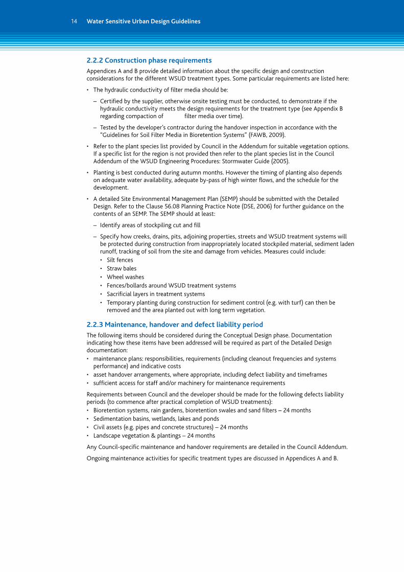
2.2.2 Construction phase requirements
Appendices A and B provide detailed information about the specific design and construction considerations for the different WSUD treatment types. Some particular requirements are listed here:
• The hydraulic conductivity of filter media should be:
– Certified by the supplier, otherwise onsite testing must be conducted, to demonstrate if the hydraulic conductivity meets the design requirements for the treatment type (see Appendix B regarding compaction of filter media over time).
– Tested by the developer’s contractor during the handover inspection in accordance with the “Guidelines for Soil Filter Media in Bioretention Systems” (FAWB, 2009).
• Refer to the plant species list provided by Council in the Addendum for suitable vegetation options. If a specific list for the region is not provided then refer to the plant species list in the Council Addendum of the WSUD Engineering Procedures: Stormwater Guide (2005).
• Planting is best conducted during autumn months. However the timing of planting also depends on adequate water availability, adequate by-pass of high winter flows, and the schedule for the development.
• A detailed Site Environmental Management Plan (SEMP) should be submitted with the Detailed Design. Refer to the Clause 56.08 Planning Practice Note (DSE, 2006) for further guidance on the contents of an SEMP. The SEMP should at least:
– Identify areas of stockpiling cut and fill
– Specify how creeks, drains, pits, adjoining properties, streets and WSUD treatment systems will be protected during construction from inappropriately located stockpiled material, sediment laden runoff, tracking of soil from the site and damage from vehicles. Measures could include:
• Silt fences • Straw bales • Wheel washes • Fences/bollards around WSUD treatment systems • Sacrificial layers in treatment systems • Temporary planting during construction for sediment control (e.g. with turf) can then be
removed and the area planted out with long term vegetation.
2.2.3 Maintenance, handover and defect liability period
The following items should be considered during the Conceptual Design phase. Documentation indicating how these items have been addressed will be required as part of the Detailed Design documentation:• maintenance plans: responsibilities, requirements (including cleanout frequencies and systems
performance) and indicative costs• asset handover arrangements, where appropriate, including defect liability and timeframes• sufficient access for staff and/or machinery for maintenance requirements
Requirements between Council and the developer should be made for the following defects liability periods (to commence after practical completion of WSUD treatments):• Bioretention systems, rain gardens, bioretention swales and sand filters – 24 months• Sedimentation basins, wetlands, lakes and ponds• Civil assets (e.g. pipes and concrete structures) – 24 months• Landscape vegetation & plantings – 24 months
Any Council-specific maintenance and handover requirements are detailed in the Council Addendum.
Ongoing maintenance activities for specific treatment types are discussed in Appendices A and B.
15
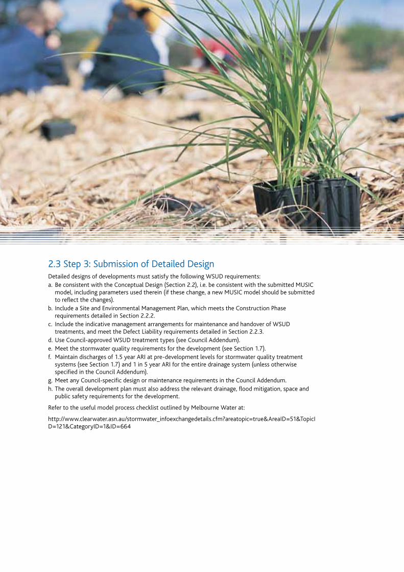
2.3 Step 3: Submission of Detailed DesignDetailed designs of developments must satisfy the following WSUD requirements:a. Be consistent with the Conceptual Design (Section 2.2), i.e. be consistent with the submitted MUSIC
model, including parameters used therein (if these change, a new MUSIC model should be submitted to reflect the changes).
b. Include a Site and Environmental Management Plan, which meets the Construction Phase requirements detailed in Section 2.2.2.
c. Include the indicative management arrangements for maintenance and handover of WSUD treatments, and meet the Defect Liability requirements detailed in Section 2.2.3.
d. Use Council-approved WSUD treatment types (see Council Addendum).e. Meet the stormwater quality requirements for the development (see Section 1.7).f. Maintain discharges of 1.5 year ARI at pre-development levels for stormwater quality treatment
systems (see Section 1.7) and 1 in 5 year ARI for the entire drainage system (unless otherwise specified in the Council Addendum).
g. Meet any Council-specific design or maintenance requirements in the Council Addendum.h. The overall development plan must also address the relevant drainage, flood mitigation, space and
public safety requirements for the development.
Refer to the useful model process checklist outlined by Melbourne Water at:
http://www.clearwater.asn.au/stormwater_infoexchangedetails.cfm?areatopic=true&AreaID=51&TopicID=121&CategoryID=1&ID=664
3. References
Comley, J., 2008, Clause 56.07-4 Implementation Toolkit for Councils, Clearwater, viewed 29 January 2010, http://www.clearwater.asn.au/stormwater_infoexchangedetails.cfm?areatopic=true&AreaID=51&TopicID=121&CategoryID=1&ID=664
Department of Environment and Conservation NSW, 2006, Managing urban stormwater: harvesting and reuse, Department of Environment and Conservation NSW, Sydney
Department of Sustainability and Environment (DSE), 2006, VPP Practice Note: Using the integrated water management provisions of Clause 56 – Residential Subdivision, DSE, viewed 29 January 2010, http://www.dse.vic.gov.au/CA256F310024B628/0/B94519854FA94273CA257213000126AD/$File/VPP_Clause_56_4-Intwaterman.pdf
Department of Sustainability and Environment (DSE), 2006, VPP Practice Note: Using the site management provisions of Clause 56 – Residential Subdivision, DSE, viewed 29 January 2010, http://www.dse.vic.gov.au/CA256F310024B628/0/B90EC6774612D38BCA2572130002E582/$File/VPP_Clause_56-3-Site_Man.pdf
EPA Victoria, 2008, Maintaining Water Sensitive Urban Design Elements, EPA Victoria, Southbank
EPA Victoria, 2003, State Environment Protection Policy (Waters of Victoria), EPA Victoria, viewed 17 December 2008, http://www.epa.vic.gov.au/about_us/legislation/water.asp#sepp_waters
FAWB, 2009, Adoption Guidelines for Stormwater Biofiltration Systems (Version 1), Facility for Advancing Water Biofiltration, Monash University
Melbourne Water, 2008, Melbourne Water Land Development Manual, Melbourne Water, viewed 29 January 2010, http://ldm.melbournewater.com.au/
Melbourne Water, 2005, WSUD Engineering Procedures: Stormwater, CSIRO Publishing, Melbourne Water
Melbourne Water, 2005, Constructed Shallow Lake Systems: Design Guidelines for Developers, Melbourne Water, viewed 29 January 2010, http://www.melbournewater.com.au/content/library/rivers_and_creeks/wetlands/Design_Guidelines_For_Shallow_Lake_Systems.pdf
Melbourne Water, 2005, Constructed Wetland Systems: Design Guidelines for Developers, Melbourne Water, viewed 29 January 2010, http://www.melbournewater.com.au/content/library/wsud/Melbourne_Water_Wetland_Design_Guide.pdf
Melbourne Water, 2009, Music Input Parameters, Melbourne Waterhttp://www.melbournewater.com.au/content/library/wsud/Guidelines_For_The_Use_Of_MUSIC.pdf
Natural Resource Management Ministerial Council, Environment Protection and Heritage Council, National Health and Medical Research Council, 2009, National Water Management Strategy Document 23 – Stormwater Harvesting and Reuse, Biotext, Canberra
Wong, T., 2006, Australian Runoff Quality – A guide to Water Sensitive Urban Design, Engineers Media, Crows Nest
Water Sensitive Urban Design Guidelines16
4. Acknowledgements
These Guidelines are based on an original January 2009 version developed by Bass Coast, Baw Baw, Cardinia, Mornington Peninsula and South Gippsland Shire Councils in partnership with Melbourne Water. The contribution of these organisations is gratefully acknowledged in the assistance it provided to developing this new version.
Parsons Brinckerhoff would particularly like to thank the following people for their valuable contributions to these guidelines:
Melbourne Water – Jamie Comley and Andrew Marshall
Hume City Council – John Davis and Danilo Isma
Macedon Ranges Shire Council – Nick Massie
Melton Shire Council – Voltaire C. David
Mitchell Shire Council – Peter Halton and Raj Rajakumar
Moorabool Shire Council – Peter Cuddy
Surf Coast Shire Council – David Mitchell and Barbara Noelker
Whittlesea City Council – Irena Krsteska, Voytek Lapinski, Robyn Lukstin, Paul Mitchell, John Pietryszyn, Greg Scott, Rod Spivey and Leah Wittingslow
Wyndham City Council – Peter Grogan, Zinta Lazdins and Michael McGlade
SMEC Urban – Steve Watters
17
Water Sensitive Urban Design Guidelines18
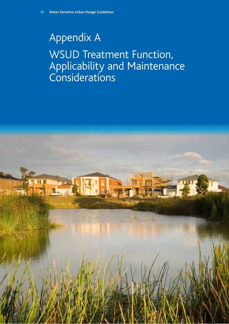
Appendix A
WSUD Treatment Function, Applicability and Maintenance Considerations
Water Sensitive Urban Design Guidelines18

The functionality, applicability and maintenance requirements of each WSUD treatment type should be carefully considered when preparing and approving designs. The following tables outline the functionality, applicability and maintenance considerations for various WSUD treatment systems. Indicative costs for the different treatment systems have also been included. These are intended to be a comparative guide only. These tables are intended to be used in conjunction with the WSUD Engineering Procedures: Stormwater Manual (Melbourne Water, 2005).
Tab
le A
-1: S
um
mar
y o
f tr
eatm
ent
fun
ctio
n, a
pp
lica
bili
ty a
nd
cost
: Ad
apte
d fr
om
: Vic
tori
an S
torm
wat
er C
om
mit
tee
(19
99)
; Wo
ng
(20
06)
; EPA
(2
00
8)
H
igh
appl
icab
ility
M
ediu
m a
pplic
abili
ty
Lo
w a
pplic
abili
tyB
iore
ten
tio
n sw
ales
Bio
rete
nti
on
bas
ins
/rai
nga
rden
sV
eget
ated
sw
ales
/ b
uff
er s
trip
sSa
nd
filt
ers
Sed
imen
tati
on
basi
ns
Co
nst
ruct
ed
wet
lan
ds
Pon
ds
and
sh
allo
w la
kes
Rai
nw
ater
ta
nks
Sto
rmw
ater
H
arve
stin
g
FUN
CT
ION
:
Wat
er q
ualit
y tr
eatm
ent
Flow
att
enua
tion
Stor
mw
ater
con
veya
nce
Part
icle
siz
e re
mo
val
Coa
rse-
Med
ium
par
ticl
es 5
00
0 μm
-125
μm
Fine
par
ticu
late
s 12
5 μm
-10
μm
Ver
y fin
e/C
ollo
idal
par
ticu
late
s 10
μm
-0.4
5 μm
Dis
solv
ed p
arti
cles
<0.
45 μ
m
Ad
dit
ion
al f
un
ctio
nLa
ndsc
ape
valu
eA
esth
etic
app
eal
Hab
itat
val
ues
Land
scap
e va
lue
Hab
itat
, vis
ual
& r
ecre
atio
n am
enit
y
Hab
itat
, vis
ual
& r
ecre
atio
n am
enit
y
Stor
mw
ater
re
-use
Hab
itat
, vis
ual
& r
ecre
atio
nal
amen
ity
APP
LIC
AB
ILIT
Y:
Med
ian
stri
p/ve
rge
Stre
ets
Med
ian
stri
p/ve
rge/
park
sSt
reet
s/m
any
Pre-
trea
tmen
t to
wet
land
Park
s/va
cant
la
ndA
esth
etic
/pos
t w
etla
ndO
n-pr
oper
tyPa
rks/
vaca
nt
land
Are
a re
quir
emen
tLa
rger
are
as
(wit
h lim
ited
pu
blic
acc
ess)
Lim
ited
spa
ceLa
rger
are
as
(wit
h lim
ited
pu
blic
acc
ess)
Lim
ited
spa
ceLa
rge
area
sLa
rge
area
sLa
rge
area
sLi
mit
ed s
pace
Larg
e ar
ea
(whe
n us
ing
an
abov
e gr
ound
st
orag
e)
Slop
e co
nsid
erat
ions
and
app
roac
h
to s
ite
cons
trai
nts
Gen
tle
slop
es
(< 5
%).
Whe
re
slop
es e
xcee
d 5%
, flo
w s
prea
ders
or
chec
k da
ms
may
be
req
uire
d.
Flat
land
. Whe
re la
nd
is s
lope
d te
rrac
es c
an
be u
sed.
Gen
tle
slop
es
(< 5
%).
Whe
re
slop
es e
xcee
d 5%
, flo
w s
prea
ders
or
chec
k da
ms
may
be
req
uire
d.
Suit
able
for
st
eepe
r sl
opes
Flat
land
Flat
land
Suit
able
for
st
eep
land
Suit
able
on
m
ost
site
sFl
at la
nd
Leve
l of
flow
con
trol
Con
veya
nce
Dis
char
geC
onve
yanc
eD
isch
arge
Dis
char
geD
isch
arge
Dis
char
geSo
urce
Dis
char
ge
IND
ICA
TIV
E C
OST
S:
Inst
alla
tion
cos
tsM
oder
ate
Mod
erat
eLo
wLo
w/M
oder
ate
Hig
hH
igh
Hig
hLo
wH
igh
Mai
nten
ance
cos
tsM
oder
ate
Mod
erat
eM
oder
ate/
Hig
hM
oder
ate
Mod
erat
e/H
igh
Mod
erat
eM
oder
ate
Low
Mod
erat
e
Ind
icat
ive
cost
s: In
dica
tive
cos
ts f
or c
ompa
riso
n pu
rpos
es o
nly
Inst
alla
tio
n co
sts:
Bas
ed o
n th
e tr
eatm
ent’
s to
tal i
nsta
lled
cost
per
hec
tare
of
catc
hmen
t. B
road
app
roxi
mat
ions
are
as
follo
ws:
• H
igh:
Gre
ater
tha
n $1
500
per
hect
are
of c
atch
men
t;
• M
oder
ate:
Bet
wee
n $5
00
and
$150
0 pe
r he
ctar
e of
cat
chm
ent;
and
•
Low
: Les
s th
an $
500
per
hect
are
of c
atch
men
t
Mai
nte
nan
ce c
ost
s: B
ased
on
the
cost
per
hec
tare
per
ann
um f
or e
ach
trea
tmen
t ty
pe. B
road
est
imat
es a
re a
s fo
llow
s:•
Hig
h: G
reat
er t
han
$250
per
hec
tare
of
catc
hmen
t pe
r an
num
; •
Mod
erat
e: B
etw
een
$10
0 an
d $2
50 p
er h
ecta
re o
f ca
tchm
ent
per
annu
m; a
nd
• Lo
w: L
ess
than
$10
0 pe
r he
ctar
e of
cat
chm
ent
per
annu
m.
19
Water Sensitive Urban Design Guidelines20
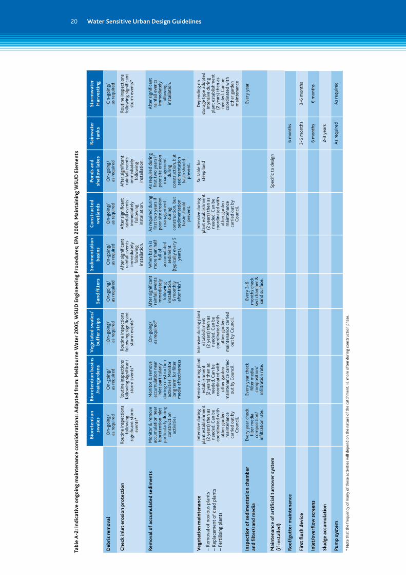
Tab
le A
-2: I
nd
icat
ive
on
goin
g m
ain
ten
ance
co
nsi
der
atio
ns:
Ad
apte
d fr
om
: Mel
bo
urn
e W
ater
20
05
, WSU
D E
ngi
nee
rin
g Pr
oce
du
res;
EPA
20
08
, Mai
nta
inin
g W
SUD
Ele
men
ts
Bio
rete
nti
on
swal
esB
iore
ten
tio
n ba
sin
s /r
ain
gard
ens
Veg
etat
ed s
wal
es/
bu
ffer
str
ips
San
d fi
lter
sSe
dim
enta
tio
n ba
sin
sC
on
stru
cted
w
etla
nd
sPo
nd
s an
d
shal
low
lake
sR
ain
wat
er
tan
ksSt
orm
wat
er
Har
vest
ing
Deb
ris
rem
ova
lO
n-go
ing/
as
req
uire
dO
n-go
ing/
as
req
uire
dO
n-go
ing/
as
req
uire
dO
n-go
ing/
as
req
uire
dO
n-go
ing/
as
req
uire
dO
n-go
ing/
as
req
uire
dO
n-go
ing/
as
req
uire
dO
n-go
ing/
as
req
uire
d
Ch
eck
inle
t er
osi
on
pro
tect
ion
Rout
ine
insp
ecti
ons
follo
win
g si
gnifi
cant
sto
rm
even
ts*
Rout
ine
insp
ecti
ons
follo
win
g si
gnifi
cant
st
orm
eve
nts*
Rout
ine
insp
ecti
ons
follo
win
g si
gnifi
cant
st
orm
eve
nts*
Aft
er s
igni
fican
t ra
infa
ll ev
ents
im
med
iate
ly
follo
win
g in
stal
lati
on.
Aft
er s
igni
fican
t ra
infa
ll ev
ents
im
med
iate
ly
follo
win
g in
stal
lati
on.
Aft
er s
igni
fican
t ra
infa
ll ev
ents
im
med
iate
ly
follo
win
g in
stal
lati
on.
Rout
ine
insp
ecti
ons
follo
win
g si
gnifi
cant
st
orm
eve
nts*
Rem
ova
l of
accu
mu
late
d se
dim
ents
Mon
itor
& r
emov
e ac
cum
ulat
ion
near
bi
oret
enti
on in
let
part
icul
arly
dur
ing
cons
truc
tion
ac
tivi
ties
.
Mon
itor
& r
emov
e ac
cum
ulat
ion
near
in
let
part
icul
arly
du
ring
con
stru
ctio
n ac
tivi
ties
. Mon
itor
lo
ng t
erm
for
filt
er
med
ia e
ffec
tive
ness
On-
goin
g/
as r
equi
red*
Aft
er s
igni
fican
t ra
infa
ll ev
ents
im
med
iate
ly
follo
win
g in
stal
lati
on.
6 m
onth
ly
afte
r th
is*.
Whe
n ba
sin
is
mor
e th
an h
alf
full
of
accu
mul
ated
se
dim
ent
(typ
ical
ly e
very
5
year
s).
As
requ
ired
dur
ing
firs
t tw
o ye
ars
if po
or s
ite
eros
ion
man
agem
ent
duri
ng
cons
truc
tion
, but
se
dim
enta
tion
ba
sin
shou
ld
prev
ent.
As
requ
ired
dur
ing
first
tw
o ye
ars
if po
or s
ite
eros
ion
man
agem
ent
duri
ng
cons
truc
tion
, but
se
dim
enta
tion
ba
sin
shou
ld
prev
ent.
Aft
er s
igni
fican
t ra
infa
ll ev
ents
im
med
iate
ly
follo
win
g
inst
alla
tion
.
Veg
etat
ion
mai
nte
nan
ce
– Re
mov
al o
f no
xiou
s pl
ants
–
Repl
acem
ent
of d
ead
plan
ts
– Fe
rtili
sing
pla
nts
Inte
nsiv
e du
ring
pl
ant
esta
blis
hmen
t (2
yea
rs)
then
as
need
ed. C
an b
e co
ordi
nate
d w
ith
othe
r ga
rden
m
aint
enan
ce
carr
ied
out
by
Cou
ncil.
Inte
nsiv
e du
ring
pla
nt
esta
blis
hmen
t
(2 y
ears
) th
en a
s ne
eded
. Can
be
coor
dina
ted
wit
h ot
her
gard
en
mai
nten
ance
car
ried
ou
t by
Cou
ncil.
Inte
nsiv
e du
ring
pla
nt
esta
blis
hmen
t
(2 y
ears
) th
en a
s ne
eded
. Can
be
coor
dina
ted
wit
h ot
her
gard
en
mai
nten
ance
car
ried
ou
t by
Cou
ncil.
Inte
nsiv
e du
ring
pl
ant
esta
blis
hmen
t (2
yea
rs)
then
as
need
ed. C
an b
e co
ordi
nate
d w
ith
othe
r ga
rden
m
aint
enan
ce
carr
ied
out
by
Cou
ncil.
Suit
able
for
st
eep
land
Dep
endi
ng o
n st
orag
e ty
pe a
dopt
ed
Inte
nsiv
e du
ring
pl
ant
esta
blis
hmen
t (2
yea
rs)
then
as
need
ed. C
an b
e co
ordi
nate
d w
ith
othe
r ga
rden
m
aint
enan
ce
Insp
ecti
on
of
sed
imen
tati
on
cham
ber
an
d fi
lter
/san
d m
edia
Ever
y ye
ar c
heck
fil
ter
med
ia
com
posi
tion
/ in
filtr
atio
n ra
te.
Ever
y ye
ar c
heck
fil
ter
med
ia
com
posi
tion
/ in
filtr
atio
n ra
te.
Ever
y 3
-6
mon
ths
chec
k se
d ch
ambe
r &
sa
nd s
urfa
ce.
Ever
y ye
ar
Mai
nte
nan
ce o
f ar
tifi
cial
tu
rno
ver
syst
em
(if
inst
alle
d)
Spec
ific
to d
esig
n
Ro
of/
gutt
er m
ain
ten
ance
6 m
onth
s
Firs
t fl
ush
dev
ice
3-6
mon
ths
3-6
mon
ths
Inle
t/o
verfl
ow
scr
een
s6
mon
ths
6 m
onth
s
Slu
dge
acc
um
ula
tio
n2-
3 ye
ars
Pum
p sy
stem
As
requ
ired
As
requ
ired
* N
ote
that
the
fre
quen
cy o
f m
any
of t
hese
act
ivit
ies
will
dep
end
on t
he n
atur
e of
the
cat
chm
ent,
ie. m
ore
ofte
n du
ring
con
stru
ctio
n ph
ase.
21
Appendix B
WSUD Treatment Measures – Design and Maintenance Considerations
Water Sensitive Urban Design Guidelines21
Water Sensitive Urban Design Guidelines22
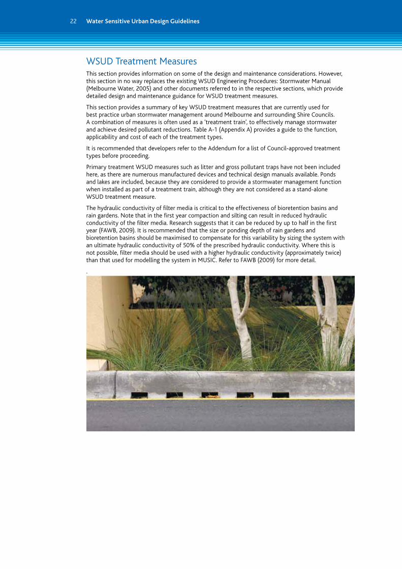
WSUD Treatment MeasuresThis section provides information on some of the design and maintenance considerations. However, this section in no way replaces the existing WSUD Engineering Procedures: Stormwater Manual (Melbourne Water, 2005) and other documents referred to in the respective sections, which provide detailed design and maintenance guidance for WSUD treatment measures.
This section provides a summary of key WSUD treatment measures that are currently used for best practice urban stormwater management around Melbourne and surrounding Shire Councils. A combination of measures is often used as a ‘treatment train’, to effectively manage stormwater and achieve desired pollutant reductions. Table A-1 (Appendix A) provides a guide to the function, applicability and cost of each of the treatment types.
It is recommended that developers refer to the Addendum for a list of Council-approved treatment types before proceeding.
Primary treatment WSUD measures such as litter and gross pollutant traps have not been included here, as there are numerous manufactured devices and technical design manuals available. Ponds and lakes are included, because they are considered to provide a stormwater management function when installed as part of a treatment train, although they are not considered as a stand-alone WSUD treatment measure.
The hydraulic conductivity of filter media is critical to the effectiveness of bioretention basins and rain gardens. Note that in the first year compaction and silting can result in reduced hydraulic conductivity of the filter media. Research suggests that it can be reduced by up to half in the first year (FAWB, 2009). It is recommended that the size or ponding depth of rain gardens and bioretention basins should be maximised to compensate for this variability by sizing the system with an ultimate hydraulic conductivity of 50% of the prescribed hydraulic conductivity. Where this is not possible, filter media should be used with a higher hydraulic conductivity (approximately twice) than that used for modelling the system in MUSIC. Refer to FAWB (2009) for more detail.
.
23
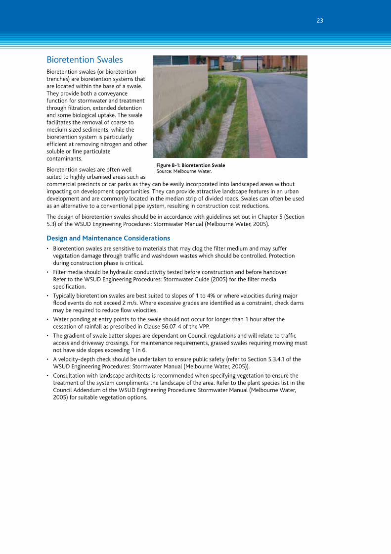
Bioretention SwalesBioretention swales (or bioretention trenches) are bioretention systems that are located within the base of a swale. They provide both a conveyance function for stormwater and treatment through filtration, extended detention and some biological uptake. The swale facilitates the removal of coarse to medium sized sediments, while the bioretention system is particularly efficient at removing nitrogen and other soluble or fine particulate contaminants.
Bioretention swales are often well suited to highly urbanised areas such as commercial precincts or car parks as they can be easily incorporated into landscaped areas without impacting on development opportunities. They can provide attractive landscape features in an urban development and are commonly located in the median strip of divided roads. Swales can often be used as an alternative to a conventional pipe system, resulting in construction cost reductions.
The design of bioretention swales should be in accordance with guidelines set out in Chapter 5 (Section 5.3) of the WSUD Engineering Procedures: Stormwater Manual (Melbourne Water, 2005).
Design and Maintenance Considerations
• Bioretention swales are sensitive to materials that may clog the filter medium and may suffer vegetation damage through traffic and washdown wastes which should be controlled. Protection during construction phase is critical.
• Filter media should be hydraulic conductivity tested before construction and before handover. Refer to the WSUD Engineering Procedures: Stormwater Guide (2005) for the filter media specification.
• Typically bioretention swales are best suited to slopes of 1 to 4% or where velocities during major flood events do not exceed 2 m/s. Where excessive grades are identified as a constraint, check dams may be required to reduce flow velocities.
• Water ponding at entry points to the swale should not occur for longer than 1 hour after the cessation of rainfall as prescribed in Clause 56.07-4 of the VPP.
• The gradient of swale batter slopes are dependant on Council regulations and will relate to traffic access and driveway crossings. For maintenance requirements, grassed swales requiring mowing must not have side slopes exceeding 1 in 6.
• A velocity-depth check should be undertaken to ensure public safety (refer to Section 5.3.4.1 of the WSUD Engineering Procedures: Stormwater Manual (Melbourne Water, 2005)).
• Consultation with landscape architects is recommended when specifying vegetation to ensure the treatment of the system compliments the landscape of the area. Refer to the plant species list in the Council Addendum of the WSUD Engineering Procedures: Stormwater Manual (Melbourne Water, 2005) for suitable vegetation options.
Figure B-1: Bioretention Swale Source: Melbourne Water.
Water Sensitive Urban Design Guidelines24
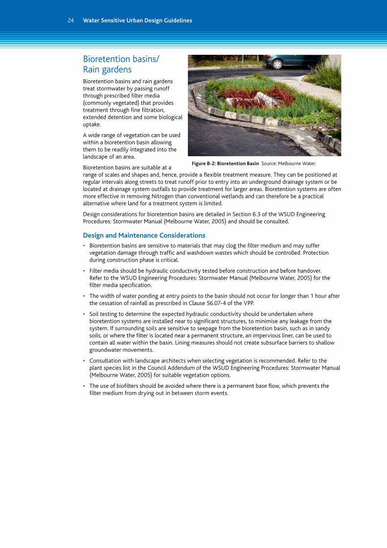
Bioretention basins/ Rain gardensBioretention basins and rain gardens treat stormwater by passing runoff through prescribed filter media (commonly vegetated) that provides treatment through fine filtration, extended detention and some biological uptake.
A wide range of vegetation can be used within a bioretention basin allowing them to be readily integrated into the landscape of an area.
Bioretention basins are suitable at a range of scales and shapes and, hence, provide a flexible treatment measure. They can be positioned at regular intervals along streets to treat runoff prior to entry into an underground drainage system or be located at drainage system outfalls to provide treatment for larger areas. Bioretention systems are often more effective in removing Nitrogen than conventional wetlands and can therefore be a practical alternative where land for a treatment system is limited.
Design considerations for bioretention basins are detailed in Section 6.3 of the WSUD Engineering Procedures: Stormwater Manual (Melbourne Water, 2005) and should be consulted.
Design and Maintenance Considerations
• Bioretention basins are sensitive to materials that may clog the filter medium and may suffer vegetation damage through traffic and washdown wastes which should be controlled. Protection during construction phase is critical.
• Filter media should be hydraulic conductivity tested before construction and before handover. Refer to the WSUD Engineering Procedures: Stormwater Manual (Melbourne Water, 2005) for the filter media specification.
• The width of water ponding at entry points to the basin should not occur for longer than 1 hour after the cessation of rainfall as prescribed in Clause 56.07-4 of the VPP.
• Soil testing to determine the expected hydraulic conductivity should be undertaken where bioretention systems are installed near to significant structures, to minimise any leakage from the system. If surrounding soils are sensitive to seepage from the bioretention basin, such as in sandy soils, or where the filter is located near a permanent structure, an impervious liner, can be used to contain all water within the basin. Lining measures should not create subsurface barriers to shallow groundwater movements.
• Consultation with landscape architects when selecting vegetation is recommended. Refer to the plant species list in the Council Addendum of the WSUD Engineering Procedures: Stormwater Manual (Melbourne Water, 2005) for suitable vegetation options.
• The use of biofilters should be avoided where there is a permanent base flow, which prevents the filter medium from drying out in between storm events.
Figure B-2: Bioretention Basin Source: Melbourne Water.
25
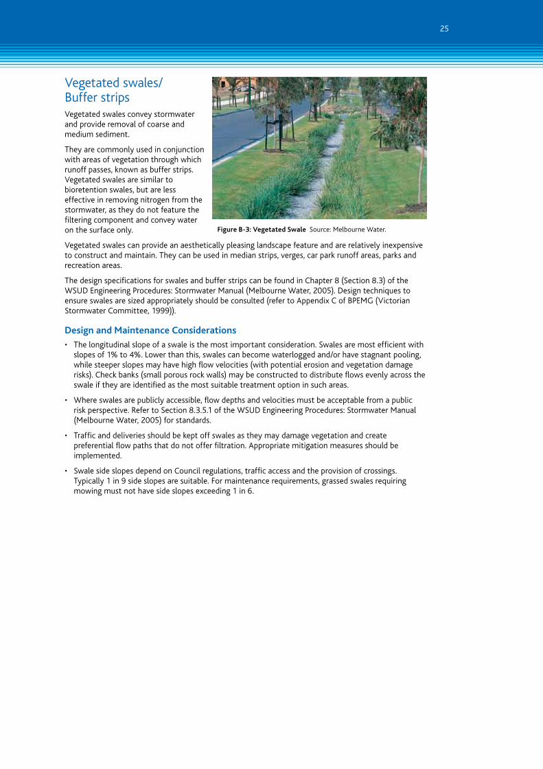
Vegetated swales/ Buffer stripsVegetated swales convey stormwater and provide removal of coarse and medium sediment.
They are commonly used in conjunction with areas of vegetation through which runoff passes, known as buffer strips. Vegetated swales are similar to bioretention swales, but are less effective in removing nitrogen from the stormwater, as they do not feature the filtering component and convey water on the surface only.
Vegetated swales can provide an aesthetically pleasing landscape feature and are relatively inexpensive to construct and maintain. They can be used in median strips, verges, car park runoff areas, parks and recreation areas.
The design specifications for swales and buffer strips can be found in Chapter 8 (Section 8.3) of the WSUD Engineering Procedures: Stormwater Manual (Melbourne Water, 2005). Design techniques to ensure swales are sized appropriately should be consulted (refer to Appendix C of BPEMG (Victorian Stormwater Committee, 1999)).
Design and Maintenance Considerations
• The longitudinal slope of a swale is the most important consideration. Swales are most efficient with slopes of 1% to 4%. Lower than this, swales can become waterlogged and/or have stagnant pooling, while steeper slopes may have high flow velocities (with potential erosion and vegetation damage risks). Check banks (small porous rock walls) may be constructed to distribute flows evenly across the swale if they are identified as the most suitable treatment option in such areas.
• Where swales are publicly accessible, flow depths and velocities must be acceptable from a public risk perspective. Refer to Section 8.3.5.1 of the WSUD Engineering Procedures: Stormwater Manual (Melbourne Water, 2005) for standards.
• Traffic and deliveries should be kept off swales as they may damage vegetation and create preferential flow paths that do not offer filtration. Appropriate mitigation measures should be implemented.
• Swale side slopes depend on Council regulations, traffic access and the provision of crossings. Typically 1 in 9 side slopes are suitable. For maintenance requirements, grassed swales requiring mowing must not have side slopes exceeding 1 in 6.
Figure B-3: Vegetated Swale Source: Melbourne Water.

Water Sensitive Urban Design Guidelines26
Sand FiltersSand filters comprise a bed of sand or other media through which runoff is passed. Gross pollutants and coarse to medium sized sediment (125 μm or larger) are retained in a sedimentation chamber before stormwater percolates through the filtration media. The filtrate is then collected by an underdrain system. These systems lack surface vegetation either because they are installed underground or because the filter media does not retain sufficient moisture to support plant growth.
Sand filters can be retrofitted and may therefore also be a suitable WSUD measure in existing developments.
The design of sand filters should follow Section 7.3 of the WSUD Engineering Procedures: Stormwater Manual (Melbourne Water, 2005). Construction advice can be obtained from Section 7.4.2 and maintenance requirements from Section 7.5 of this document.
Design and Maintenance Considerations
Sand filters are particularly useful in areas of limited space where treatment is best achieved underground. They are suited to upstream areas where constructed wetlands are unfeasible.
• Regular maintenance is required to ensure the sand filter media does not become clogged with accumulated sediments.
• Water lost from the sand filter to the surrounding soil may be an issue if they are installed near to significant structures. The surrounding soils should be tested (particularly to determine their hydraulic conductivity). An impervious liner can be used to contain all water in the form of a flexible membrane or concrete casing.
• Large sand filters lacking vegetation may be unattractive.
• Unsuitable for highly disturbed catchments or those with high sediment yields (unless pre-treatment is proposed to protect the system).
Figure B-4: Sand Filter Source: Melbourne Water.
27
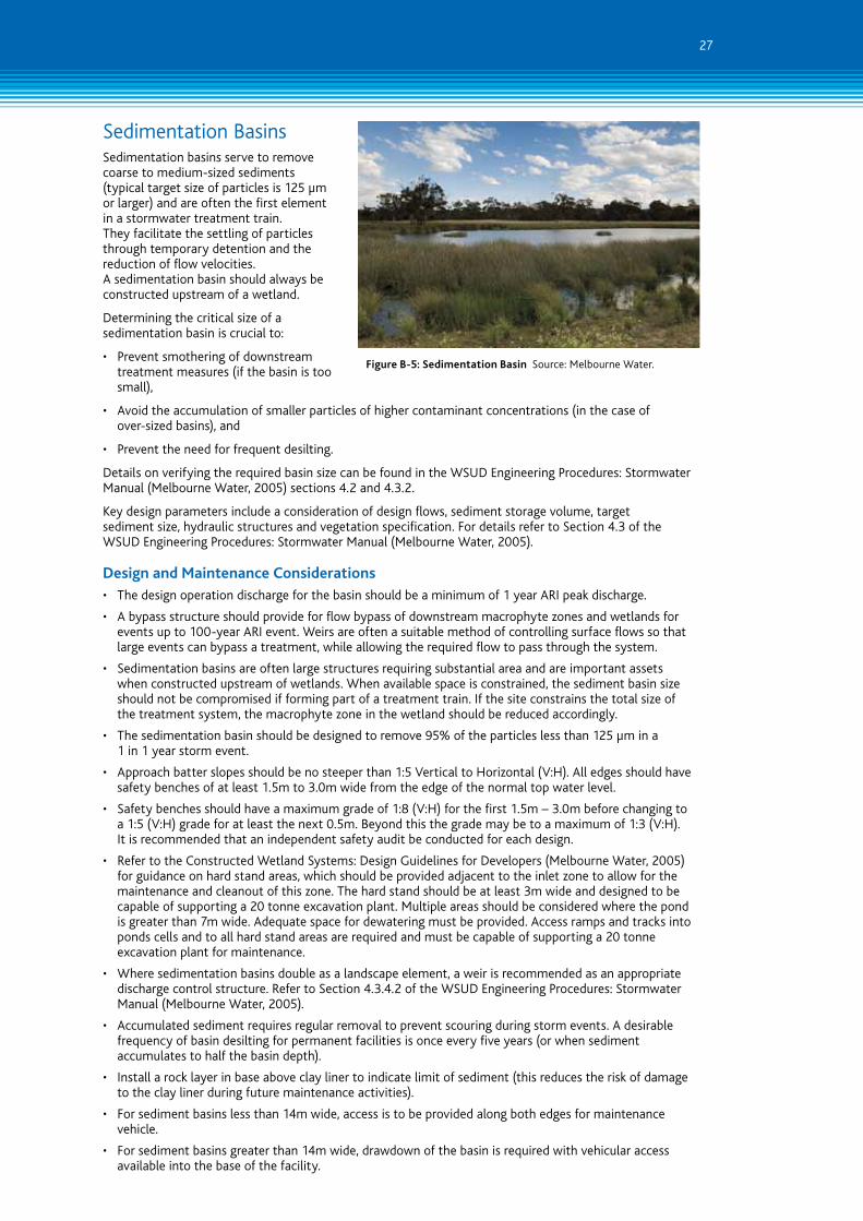
Sedimentation BasinsSedimentation basins serve to remove coarse to medium-sized sediments (typical target size of particles is 125 μm or larger) and are often the first element in a stormwater treatment train. They facilitate the settling of particles through temporary detention and the reduction of flow velocities. A sedimentation basin should always be constructed upstream of a wetland.
Determining the critical size of a sedimentation basin is crucial to:
• Prevent smothering of downstream treatment measures (if the basin is too small),
• Avoid the accumulation of smaller particles of higher contaminant concentrations (in the case of over-sized basins), and
• Prevent the need for frequent desilting.
Details on verifying the required basin size can be found in the WSUD Engineering Procedures: Stormwater Manual (Melbourne Water, 2005) sections 4.2 and 4.3.2.
Key design parameters include a consideration of design flows, sediment storage volume, target sediment size, hydraulic structures and vegetation specification. For details refer to Section 4.3 of the WSUD Engineering Procedures: Stormwater Manual (Melbourne Water, 2005).
Design and Maintenance Considerations• The design operation discharge for the basin should be a minimum of 1 year ARI peak discharge.
• A bypass structure should provide for flow bypass of downstream macrophyte zones and wetlands for events up to 100-year ARI event. Weirs are often a suitable method of controlling surface flows so that large events can bypass a treatment, while allowing the required flow to pass through the system.
• Sedimentation basins are often large structures requiring substantial area and are important assets when constructed upstream of wetlands. When available space is constrained, the sediment basin size should not be compromised if forming part of a treatment train. If the site constrains the total size of the treatment system, the macrophyte zone in the wetland should be reduced accordingly.
• The sedimentation basin should be designed to remove 95% of the particles less than 125 μm in a 1 in 1 year storm event.
• Approach batter slopes should be no steeper than 1:5 Vertical to Horizontal (V:H). All edges should have safety benches of at least 1.5m to 3.0m wide from the edge of the normal top water level.
• Safety benches should have a maximum grade of 1:8 (V:H) for the first 1.5m – 3.0m before changing to a 1:5 (V:H) grade for at least the next 0.5m. Beyond this the grade may be to a maximum of 1:3 (V:H). It is recommended that an independent safety audit be conducted for each design.
• Refer to the Constructed Wetland Systems: Design Guidelines for Developers (Melbourne Water, 2005) for guidance on hard stand areas, which should be provided adjacent to the inlet zone to allow for the maintenance and cleanout of this zone. The hard stand should be at least 3m wide and designed to be capable of supporting a 20 tonne excavation plant. Multiple areas should be considered where the pond is greater than 7m wide. Adequate space for dewatering must be provided. Access ramps and tracks into ponds cells and to all hard stand areas are required and must be capable of supporting a 20 tonne excavation plant for maintenance.
• Where sedimentation basins double as a landscape element, a weir is recommended as an appropriate discharge control structure. Refer to Section 4.3.4.2 of the WSUD Engineering Procedures: Stormwater Manual (Melbourne Water, 2005).
• Accumulated sediment requires regular removal to prevent scouring during storm events. A desirable frequency of basin desilting for permanent facilities is once every five years (or when sediment accumulates to half the basin depth).
• Install a rock layer in base above clay liner to indicate limit of sediment (this reduces the risk of damage to the clay liner during future maintenance activities).
• For sediment basins less than 14m wide, access is to be provided along both edges for maintenance vehicle.
• For sediment basins greater than 14m wide, drawdown of the basin is required with vehicular access available into the base of the facility.
Figure B-5: Sedimentation Basin Source: Melbourne Water.

Water Sensitive Urban Design Guidelines28
Constructed WetlandsConstructed wetland systems are shallow, extensively vegetated water bodies that remove pollutants through enhanced sedimentation, fine filtration and pollutant uptake processes. Stormwater runoff is passed slowly through the vegetated areas, which filter sediments and pollutants, and biofilms establish on the plants, which absorb nutrients and other contaminants. Wetlands are well suited to treat large volumes of stormwater runoff and have the advantage of improving local amenity and providing habitat diversity. Key design issues to consider include: verifying the size and configuration for treatment; determining design flows; designing the inlet zone (see sedimentation basins); layout of the macrophyte zone; hydraulic structures; selecting plant species and planting densities and providing maintenance.
Refer to the following documents for detail:
• Section 9.3 of the WSUD Engineering Procedures: Stormwater Manual (Melbourne Water, 2005);
• Section 7.9.2 and Appendix G of the Urban Stormwater: Best Practice Environmental Management Guidelines (Victorian Stormwater Committee, 1999); and
• Constructed Wetland Systems: Design Guidelines for Developers (Melbourne Water, 2005).
Design and Maintenance Considerations• The constructed wetland should treat at least 90% of Mean Annual Runoff through the use of a stored event
volume above the normal standing water level of the wetland.
• A high flow bypass should be capable of taking flows in excess of design flows (typically a 1 in 1 year event).
• The wetland design must meet safety requirements and implement reasonable safety measures. This includes fencing, safety batters, signage and benching. Refer to Section 5 of the Constructed Wetland Systems: Design Guidelines for Developers (Melbourne Water, 2005) for detail. Health and Safety considerations for maintenance staff should also be addressed. It is recommended that an independent safety audit be conducted for each design.
• Approach batter slopes should be no steeper than 1:5 Vertical to Horizontal (V:H). All edges should have safety benches of at least 1.5m to 3.0m wide from the edge of the normal top water level.
• Safety benches should have a maximum grade of 1:8 (V:H) for the first 1.5m – 3.0m before changing to a 1:5 (V:H) grade for at least the next 0.5m. Beyond this, may be up to a maximum of 1:3 (V:H). The safety bench should be densely planted with emergent macrophytes such that casual entry will be difficult.
• Refer to the Constructed Wetland Systems: Design Guidelines for Developers (Melbourne Water, 2005) for guidance on hard stand areas, which should be provided adjacent to the inlet zone to allow for the maintenance and cleanout of this zone.
• The following measures may be taken to reduce the prevalence of mosquitoes: Provide access for mosquito predators such as fish and predatory insects; Maintain natural water level fluctuations to disturb the breeding cycle of some mosquito species; and provide sufficient gross pollutant control at the inlet such that litter does not accumulate and provide breeding habitat.
• Ensure that the required detention time is achieved by using outlet risers to control flows.
• The riser outlet pipe should be sized to act as an emergency overflow equivalent to the one year ARI peak discharge.
• A minimum of a 0.3m freeboard for the embankment is required.
• Where possible, wetlands should be constructed in the base of retarding basins to reduce land requirement.
• When considering macrophyte zone layout, it is important to optimise hydraulic efficiency (i.e. reduce dead zones and short circuiting of water). The optimal hydraulic efficiency value for constructed wetlands should be not less than 0.5 and greater than 0.7 where possible. Refer to Section 9.3.3 and Figure 9.6 in the WSUD Engineering Procedures: Stormwater Manual (Melbourne Water, 2005).
• The wetland should be divided into four macrophyte zones, an open water zone and a littoral zone. The percentage allocation of each zone is outlined in Table 9.2, Section 9.6.3 of the WSUD Engineering Procedures: Stormwater Manual (Melbourne Water, 2005) and should be followed. Refer to the plant species list in the Council Addendum of the WSUD Engineering Procedures: Stormwater Manual (Melbourne Water, 2005) for suitable vegetation options.
• Wetlands require large areas of land for construction and are unsuited to steeply sloping land.
• A geotechnical investigation is required prior to design to determine soil profiles and infiltration rates. Hydrogeological investigations may also be required in areas where there is a likelihood of groundwater discharge or high seasonal water tables.
Figure B-6: Constructed wetland macrophyte zone Source: Melbourne Water.
29
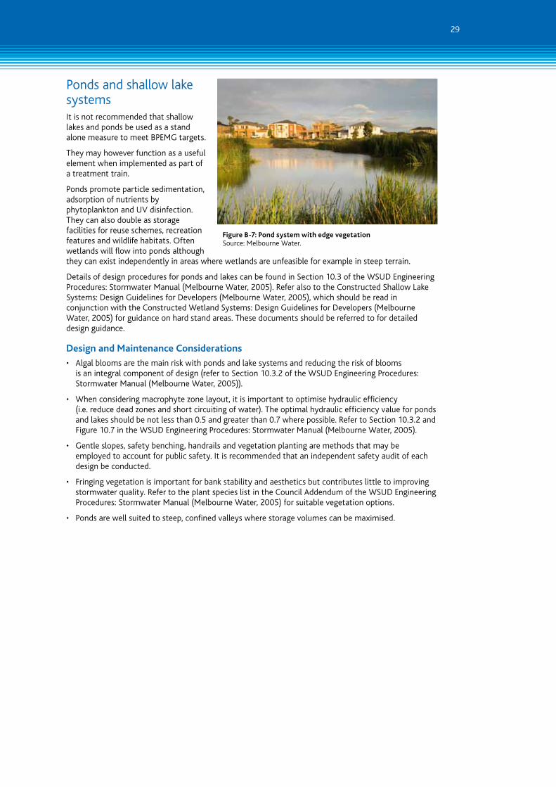
Ponds and shallow lake systemsIt is not recommended that shallow lakes and ponds be used as a stand alone measure to meet BPEMG targets.
They may however function as a useful element when implemented as part of a treatment train.
Ponds promote particle sedimentation, adsorption of nutrients by phytoplankton and UV disinfection. They can also double as storage facilities for reuse schemes, recreation features and wildlife habitats. Often wetlands will flow into ponds although they can exist independently in areas where wetlands are unfeasible for example in steep terrain.
Details of design procedures for ponds and lakes can be found in Section 10.3 of the WSUD Engineering Procedures: Stormwater Manual (Melbourne Water, 2005). Refer also to the Constructed Shallow Lake Systems: Design Guidelines for Developers (Melbourne Water, 2005), which should be read in conjunction with the Constructed Wetland Systems: Design Guidelines for Developers (Melbourne Water, 2005) for guidance on hard stand areas. These documents should be referred to for detailed design guidance.
Design and Maintenance Considerations
• Algal blooms are the main risk with ponds and lake systems and reducing the risk of blooms is an integral component of design (refer to Section 10.3.2 of the WSUD Engineering Procedures: Stormwater Manual (Melbourne Water, 2005)).
• When considering macrophyte zone layout, it is important to optimise hydraulic efficiency (i.e. reduce dead zones and short circuiting of water). The optimal hydraulic efficiency value for ponds and lakes should be not less than 0.5 and greater than 0.7 where possible. Refer to Section 10.3.2 and Figure 10.7 in the WSUD Engineering Procedures: Stormwater Manual (Melbourne Water, 2005).
• Gentle slopes, safety benching, handrails and vegetation planting are methods that may be employed to account for public safety. It is recommended that an independent safety audit of each design be conducted.
• Fringing vegetation is important for bank stability and aesthetics but contributes little to improving stormwater quality. Refer to the plant species list in the Council Addendum of the WSUD Engineering Procedures: Stormwater Manual (Melbourne Water, 2005) for suitable vegetation options.
• Ponds are well suited to steep, confined valleys where storage volumes can be maximised.
Figure B-7: Pond system with edge vegetation Source: Melbourne Water.
Water Sensitive Urban Design Guidelines30
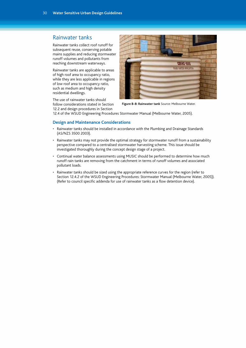
Rainwater tanksRainwater tanks collect roof runoff for subsequent reuse, conserving potable mains supplies and reducing stormwater runoff volumes and pollutants from reaching downstream waterways.
Rainwater tanks are applicable to areas of high roof area to occupancy ratio, while they are less applicable in regions of low roof area to occupancy ratio, such as medium and high density residential dwellings.
The use of rainwater tanks should follow considerations stated in Section 12.2 and design procedures in Section 12.4 of the WSUD Engineering Procedures Stormwater Manual (Melbourne Water, 2005).
Design and Maintenance Considerations
• Rainwater tanks should be installed in accordance with the Plumbing and Drainage Standards (AS/NZS 3500 2003).
• Rainwater tanks may not provide the optimal strategy for stormwater runoff from a sustainability perspective compared to a centralised stormwater harvesting scheme. This issue should be investigated thoroughly during the concept design stage of a project.
• Continual water balance assessments using MUSIC should be performed to determine how much runoff rain tanks are removing from the catchment in terms of runoff volumes and associated pollutant loads.
• Rainwater tanks should be sized using the appropriate reference curves for the region (refer to Section 12.4.2 of the WSUD Engineering Procedures: Stormwater Manual (Melbourne Water, 2005)). (Refer to council specific addenda for use of rainwater tanks as a flow detention device).
Figure B-8: Rainwater tank Source: Melbourne Water.

31
Stormwater HarvestingStormwater harvesting systems collect stormwater runoff, typically from stormwater drains, for subsequent reuse. Stormwater harvesting is becoming an increasingly important component of stormwater management with the benefits of both reducing potable water use and reducing the volumes of runoff and pollutants entering the downstream waterways.
Stormwater harvesting systems generally consist of the following components: collection, storage, treatment and distribution (Department of Environment and Conservation NSW, 2006). The storage type for these schemes can vary, however they are commonly designed as storage tanks (either above or below ground) or open water ponds or dams.
Stormwater harvesting and reuse is applicable to various uses including: industrial or commercial uses, residential uses, and for irrigation of public parks or recreation reserves. They are typically a centralised system, and may require a relatively large area, particularly if using above ground storage.
The use of stormwater harvesting systems should follow considerations stated in the National Water Quality Management Strategy Document 23 – Stormwater Harvesting and Reuse (Natural Resource Management Ministerial Council, Environment Protection and Heritage Council, National Health and Medical Research Council, 2009).
Design and Maintenance Considerations
• Public health and environmental risks need to be addressed in the design. Additional treatment of the harvested stormwater runoff may be required before it is reused, depending on the quality of the stormwater captured and the required quality of water for the end-users (refer to National Water Quality Management Strategy Document 23 – Stormwater Harvesting and Reuse, 2009)
• It is necessary to address all of the public safety risks, particularly for open water storages, including side slopes, safety benching, fencing and appropriate signage. It is recommended that an independent safety audit of each design be conducted.
• All on site plumbing work to be done in accordance with the Plumbing and Drainage Standards (AS/NZS 3500 2003).
• Continual water balance assessments using MUSIC should be performed to determine how much runoff stormwater harvesting systems are removing from the catchment in terms of runoff volumes and associated pollutant loads. It is recommended that a longer period of rainfall data is used in MUSIC to more accurately model the stormwater harvesting systems.
• Maintenance for centralised stormwater harvesting systems will potentially be more consistent and reliable than that of distributed rainwater tanks, as it will typically rely on only one organisation (such as the Council) rather than individual householders (Department of Environment and Conservation NSW, 2006).
• The benefits of both stormwater harvesting schemes and rainwater tanks should be investigated during the concept design phase to determine the preferred option to best suit the development site.
Figure B-9: Royal Park Source: Melbourne Water.
Figure B-10: Stormwater harvesting Source: Melbourne Water.

Melbourne Water 100 Wellington Parade, East Melbourne PO Box 4342 Melbourne Victoria 3001 Telephone 131 722 Facsimile 03 9235 7200
melbournewater.com.au
For information on Melbourne’s water resources in langauges other than English, call 131 722 or visit melbournewater.com.au and click on the Community Langauges link.
ISBN 978-1-921603-81-5 (print) ISBN 978-1-921603-82-2 (web)
Published November 2010.
© Copyright November 2010 Melbourne Water, Hume City Council, Macedon Ranges Shire Council, Shire of Melton, Mitchell Shire Council, Moorabool Shire Council, City of Whittlesea and Wyndham City Council. All rights reserved. No part of this document may be reproduced, stored in a retrieval system, photocopied or otherwise dealt with without the prior written permission.
Disclaimer: This publication may be of assistance to you but Melbourne Water, Hume City Council, Macedon Ranges Shire Council, Shire of Melton, Mitchell Shire Council, Moorabool Shire Council, City of Whittlesea and Wyndham City Council and these organisations’ employees do not guarantee that the publication is without flaw of any kind or is wholly appropriate for your particular purposes and therefore disclaims all liability for any error, loss or other consequence which may arise from you relying on any information in this publication.
These guidelines are a healthy waterways initiative in partnership between Melbourne Water and participating councils.