Embed Size (px)
Citation preview

Design Criteria and Secrets to Success, Part 1
T. Andrew Earles, Ph.D., P.E., D.WRE Wright Water Engineers, Inc.
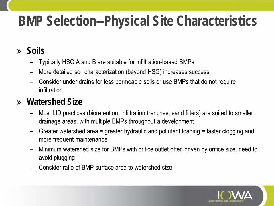
BMP Selection--Physical Site Characteristics
» Soils – Typically HSG A and B are suitable for infiltration-based BMPs – More detailed soil characterization (beyond HSG) increases success – Consider under drains for less permeable soils or use BMPs that do not require
infiltration
» Watershed Size – Most LID practices (bioretention, infiltration trenches, sand filters) are suited to smaller
drainage areas, with multiple BMPs throughout a development – Greater watershed area = greater hydraulic and pollutant loading = faster clogging and
more frequent maintenance – Minimum watershed size for BMPs with orifice outlet often driven by orifice size, need to
avoid plugging – Consider ratio of BMP surface area to watershed size
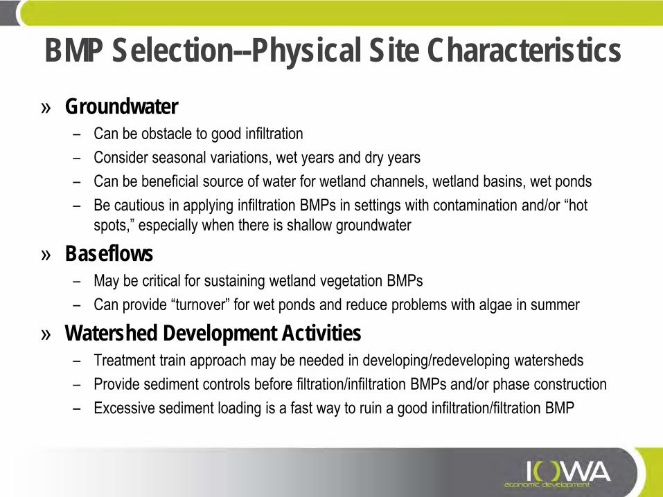
BMP Selection--Physical Site Characteristics » Groundwater
– Can be obstacle to good infiltration – Consider seasonal variations, wet years and dry years – Can be beneficial source of water for wetland channels, wetland basins, wet ponds – Be cautious in applying infiltration BMPs in settings with contamination and/or “hot
spots,” especially when there is shallow groundwater
» Baseflows – May be critical for sustaining wetland vegetation BMPs – Can provide “turnover” for wet ponds and reduce problems with algae in summer
» Watershed Development Activities – Treatment train approach may be needed in developing/redeveloping watersheds – Provide sediment controls before filtration/infiltration BMPs and/or phase construction – Excessive sediment loading is a fast way to ruin a good infiltration/filtration BMP
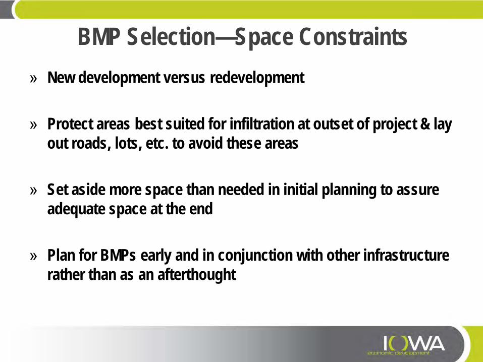
BMP Selection—Space Constraints » New development versus redevelopment
» Protect areas best suited for infiltration at outset of project & lay
out roads, lots, etc. to avoid these areas
» Set aside more space than needed in initial planning to assure adequate space at the end
» Plan for BMPs early and in conjunction with other infrastructure rather than as an afterthought
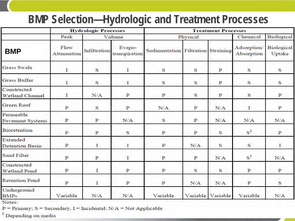
BMP Selection—Hydrologic and Treatment Processes
BMP
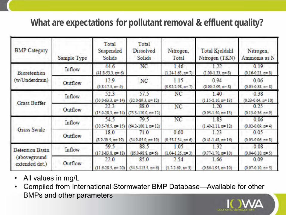
What are expectations for pollutant removal & effluent quality?
• All values in mg/L • Compiled from International Stormwater BMP Database—Available for other
BMPs and other parameters
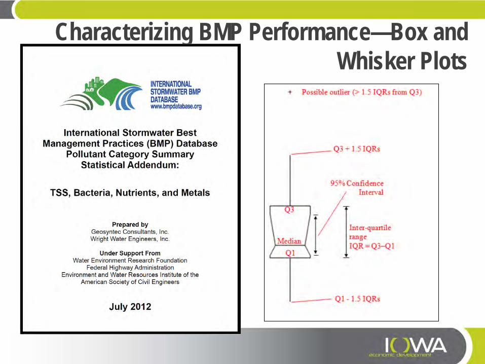
Characterizing BMP Performance—Box and Whisker Plots
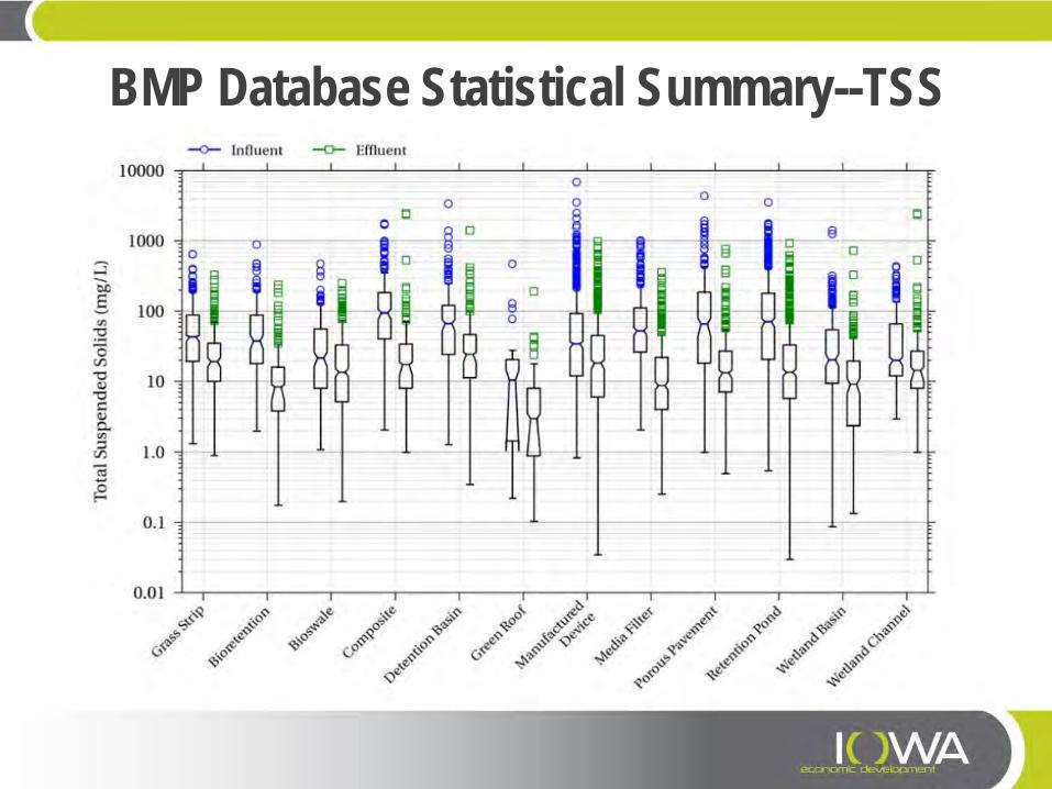
BMP Database Statistical Summary--TSS
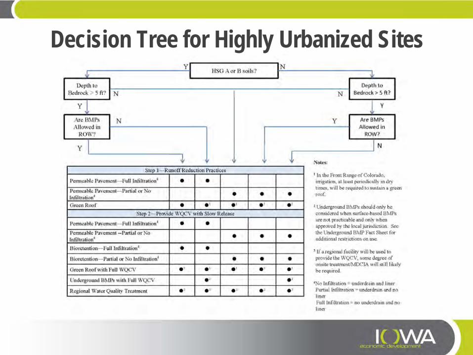
Decision Tree for Highly Urbanized Sites

Decision Tree for
Conventional Sites

Vegetated Swales and Buffers
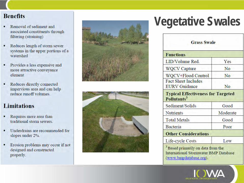
Vegetative Swales
Vegetative Swales—Key Design Criteria » Typically sized for water quality event for pollutant removal, but must check
for larger events as well. Account for fully developed conditions. » Maximize hydraulic residence time (V/Q):
– Maximize length – Decrease slope – Increase cross-sectional area – Check dams/berms to encourage ponding & infiltration.
» Typical slope range 1 – 2% but can be up to 3 or 4% in areas with non-erosive soils and good vegetative cover.
» Underdrains recommended for slopes < 2%. » Use gentle side slopes, milder than 4H:1V for best water quality results,
steeper than 3H:1V may be difficult to mow.
Vegetative Swales—Key Design Criteria
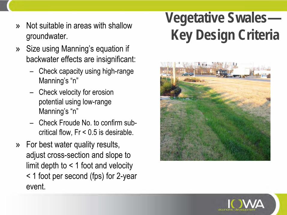
» Not suitable in areas with shallow groundwater.
» Size using Manning’s equation if backwater effects are insignificant: – Check capacity using high-range
Manning’s “n” – Check velocity for erosion
potential using low-range Manning’s “n”
– Check Froude No. to confirm sub-critical flow, Fr < 0.5 is desirable.
» For best water quality results, adjust cross-section and slope to limit depth to < 1 foot and velocity < 1 foot per second (fps) for 2-year event.
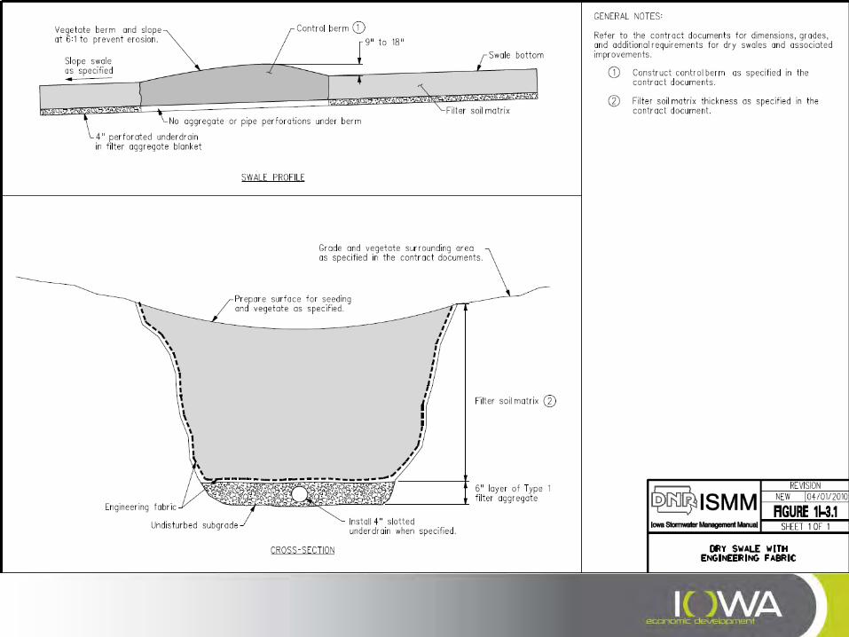
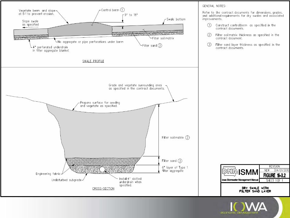
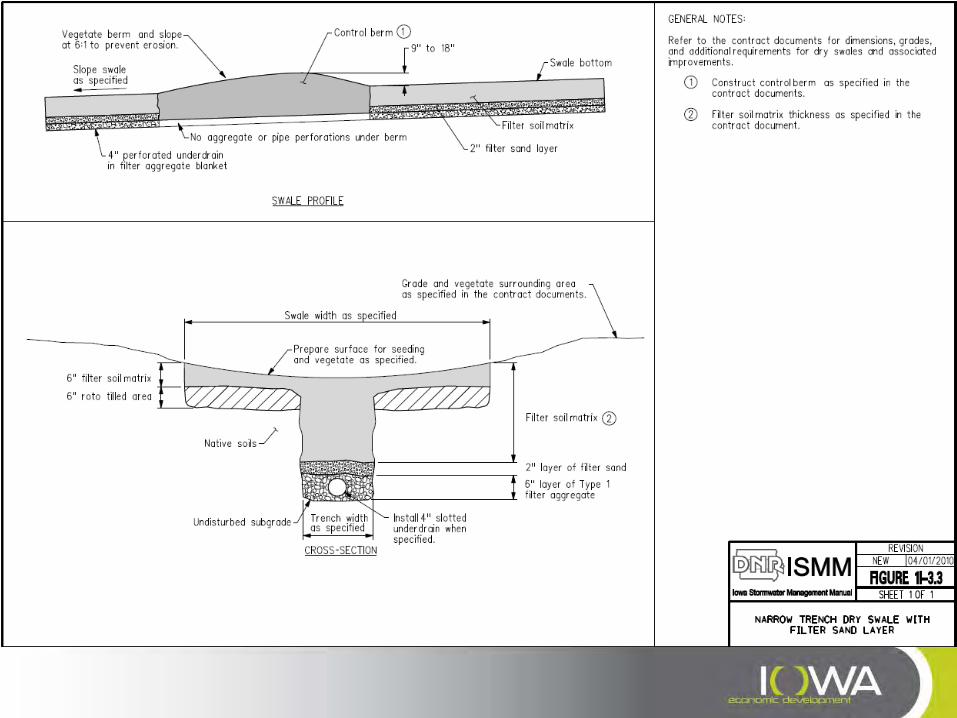
Vegetative Swales—Installation & Maintenance
» Perform fine grading, soil amendment, and seeding only after upgradient surfaces have been stabilized and utility crossings have been completed.
» Avoid compaction of soils to preserve infiltration capacities. » Weed the area during the establishment of vegetation by hand or mowing.
Mechanical weed control is preferred over chemical treatment. » Protect the swale from other construction activities. » When using an underdrain, ensure no filter sock is placed on the pipe. » Locating swales in prominent locations on site, as a part of landscaping, will
encourage upkeep and maintenance. » Provide access for mowing equipment and avoid plantings that make mowing
operations overly difficult.
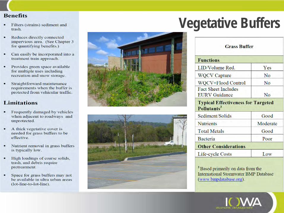
Vegetative Buffers
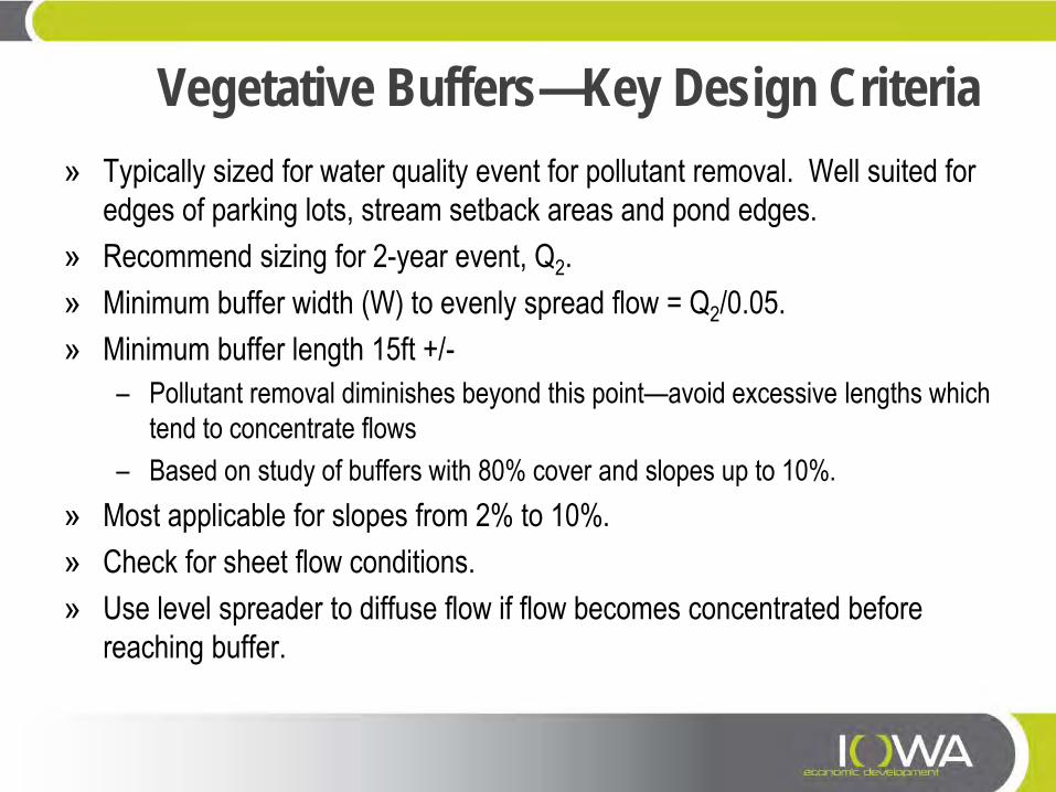
Vegetative Buffers—Key Design Criteria » Typically sized for water quality event for pollutant removal. Well suited for
edges of parking lots, stream setback areas and pond edges. » Recommend sizing for 2-year event, Q2. » Minimum buffer width (W) to evenly spread flow = Q2/0.05. » Minimum buffer length 15ft +/-
– Pollutant removal diminishes beyond this point—avoid excessive lengths which tend to concentrate flows
– Based on study of buffers with 80% cover and slopes up to 10%. » Most applicable for slopes from 2% to 10%. » Check for sheet flow conditions. » Use level spreader to diffuse flow if flow becomes concentrated before
reaching buffer.
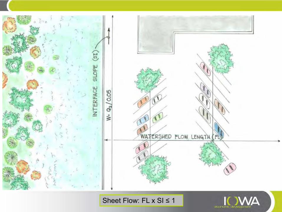
Sheet Flow: FL x SI ≤ 1


Source: www.CASFM.org
Level Spreaders
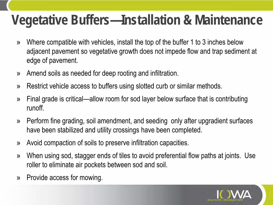
Vegetative Buffers—Installation & Maintenance » Where compatible with vehicles, install the top of the buffer 1 to 3 inches below
adjacent pavement so vegetative growth does not impede flow and trap sediment at edge of pavement.
» Amend soils as needed for deep rooting and infiltration. » Restrict vehicle access to buffers using slotted curb or similar methods. » Final grade is critical—allow room for sod layer below surface that is contributing
runoff. » Perform fine grading, soil amendment, and seeding only after upgradient surfaces
have been stabilized and utility crossings have been completed. » Avoid compaction of soils to preserve infiltration capacities. » When using sod, stagger ends of tiles to avoid preferential flow paths at joints. Use
roller to eliminate air pockets between sod and soil. » Provide access for mowing.

Infiltration Practices
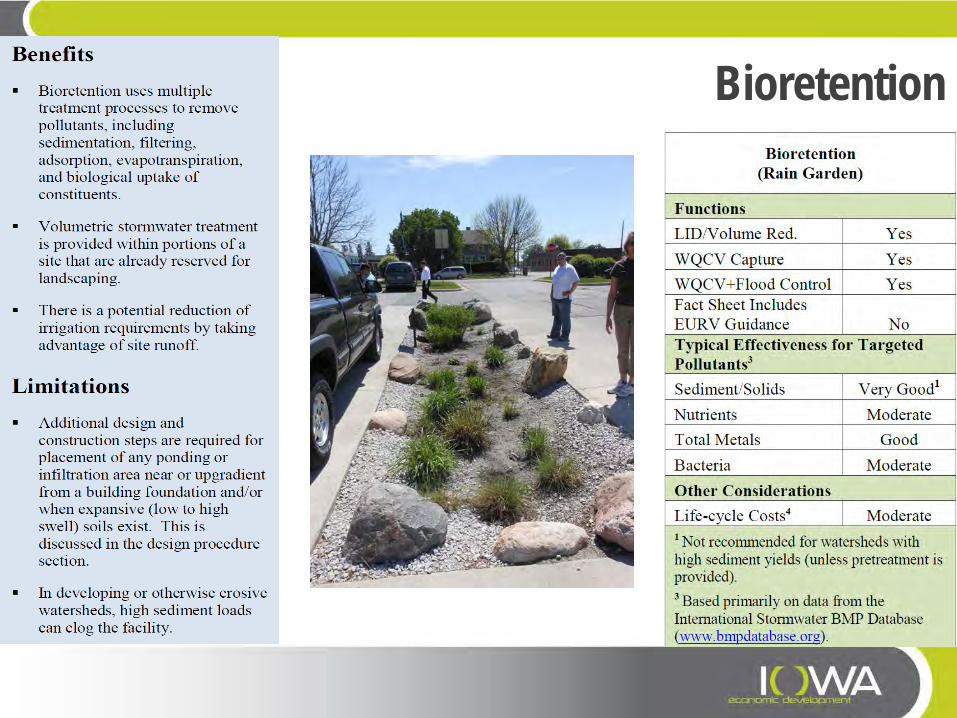
Bioretention

Infiltration Practices
• Infiltration Trenches • Infiltration Basins • Bioretention & Raingardens • Soil Quality Restoration • Native Landscaping
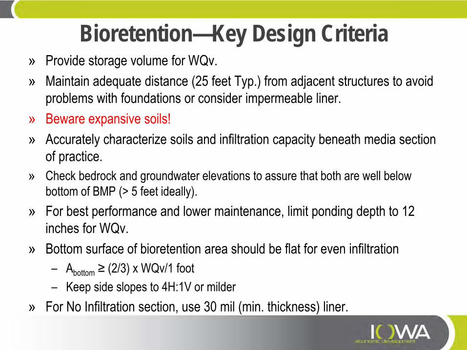
Bioretention—Key Design Criteria » Provide storage volume for WQv. » Maintain adequate distance (25 feet Typ.) from adjacent structures to avoid
problems with foundations or consider impermeable liner. » Beware expansive soils! » Accurately characterize soils and infiltration capacity beneath media section
of practice. » Check bedrock and groundwater elevations to assure that both are well below
bottom of BMP (> 5 feet ideally). » For best performance and lower maintenance, limit ponding depth to 12
inches for WQv. » Bottom surface of bioretention area should be flat for even infiltration
– Abottom ≥ (2/3) x WQv/1 foot – Keep side slopes to 4H:1V or milder
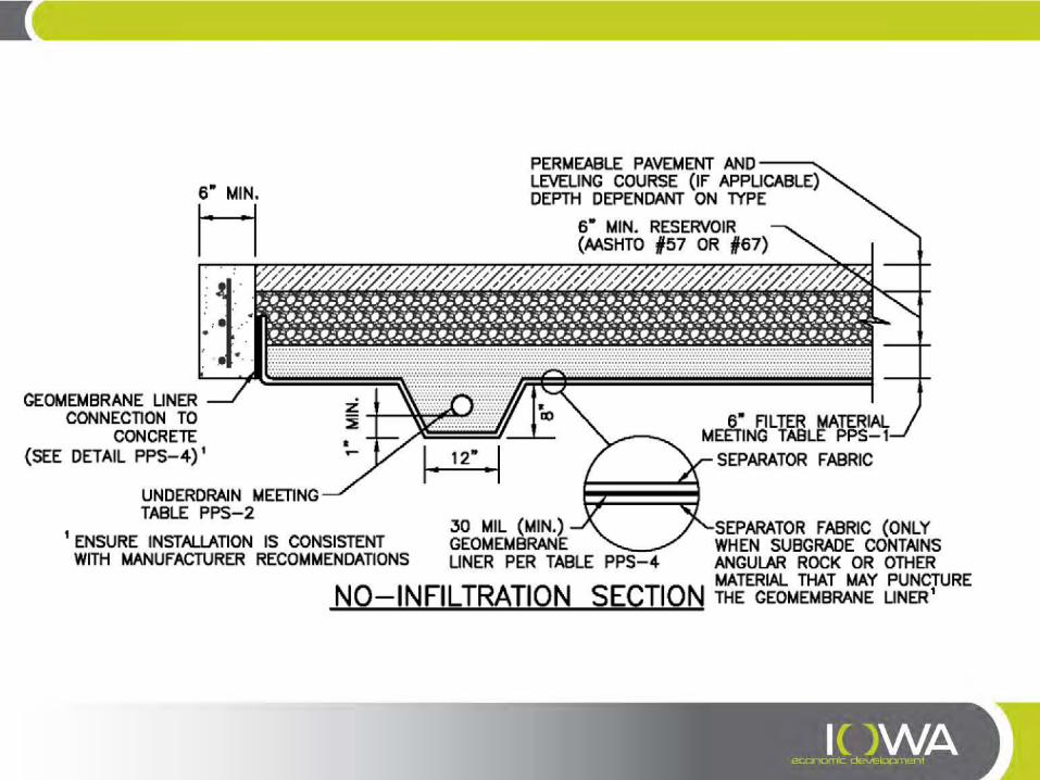
» For No Infiltration section, use 30 mil (min. thickness) liner.
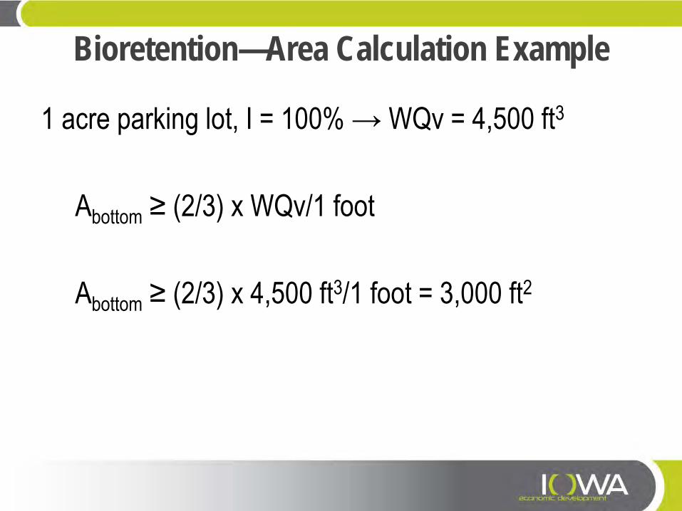
Bioretention—Area Calculation Example
1 acre parking lot, I = 100% → WQv = 4,500 ft3 Abottom ≥ (2/3) x WQv/1 foot Abottom ≥ (2/3) x 4,500 ft3/1 foot = 3,000 ft2
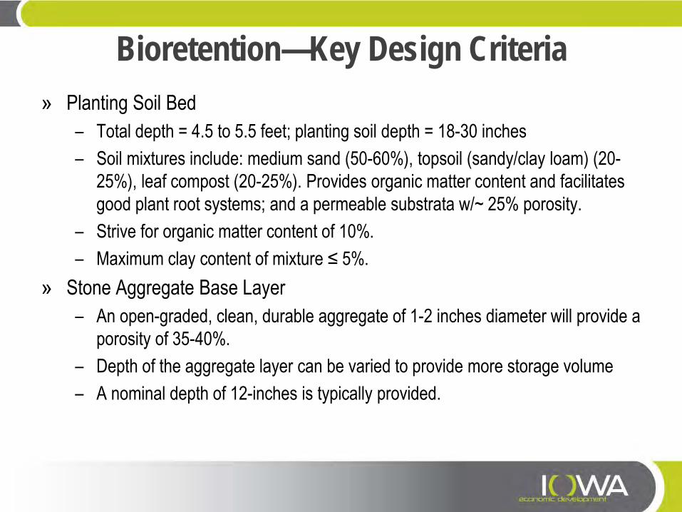
Bioretention—Key Design Criteria » Planting Soil Bed
– Total depth = 4.5 to 5.5 feet; planting soil depth = 18-30 inches – Soil mixtures include: medium sand (50-60%), topsoil (sandy/clay loam) (20-
25%), leaf compost (20-25%). Provides organic matter content and facilitates good plant root systems; and a permeable substrata w/~ 25% porosity.
– Strive for organic matter content of 10%. – Maximum clay content of mixture ≤ 5%.
» Stone Aggregate Base Layer – An open-graded, clean, durable aggregate of 1-2 inches diameter will provide a
porosity of 35-40%. – Depth of the aggregate layer can be varied to provide more storage volume – A nominal depth of 12-inches is typically provided.
Bioretention—Alternate Media (UDFCD) » Rain Garden Compost Mixture (by volume)
– 50% Class 1 STA registered compost (approximate bulk density 1000 lbs/CY) – 50% loosely packed shredded paper (approximate bulk density 50 to 100
lbs/CY) – When using diamond cut shredded paper or tightly packed paper, use the bulk
densities provided to mix by weight.
» Rain Garden Growing Medium – The supplier should premix the rain garden compost mixture (above) with
coarse sand, in the following proportions, prior to delivery to the site: – 15% rain garden compost mixture described above (by volume) – 85% coarse sand (by volume)
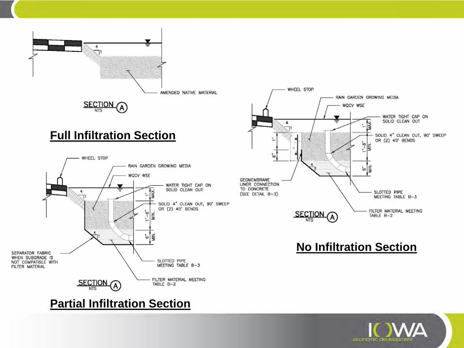
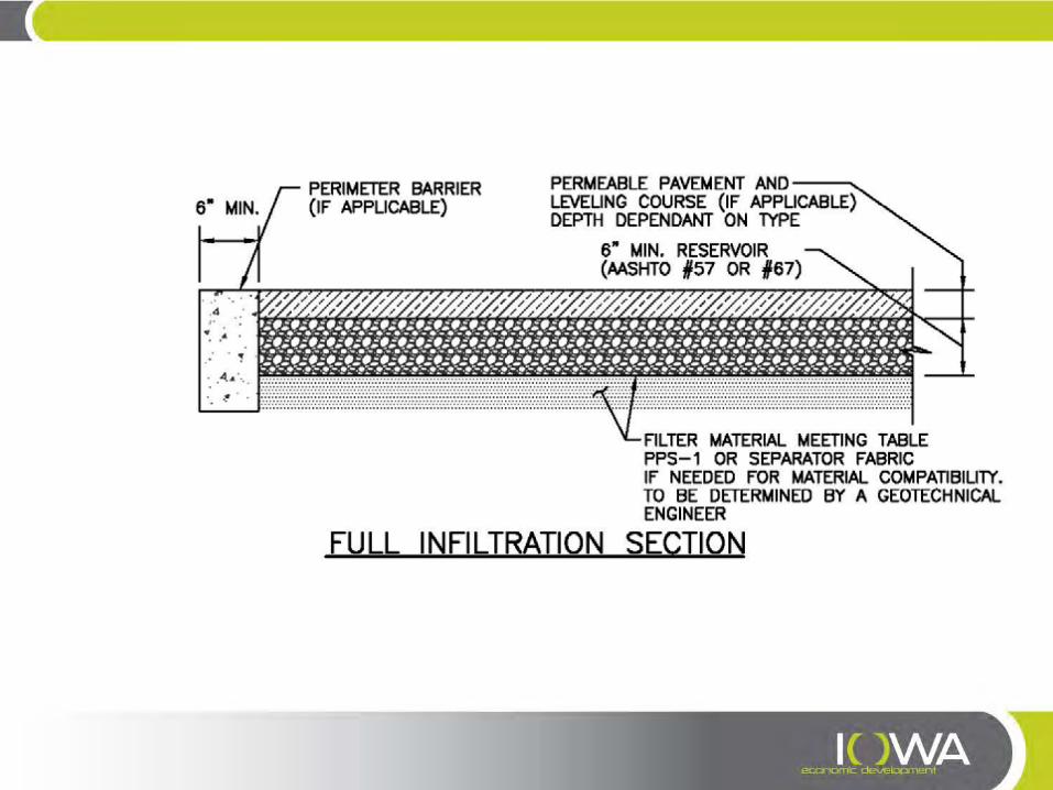
Full Infiltration Section
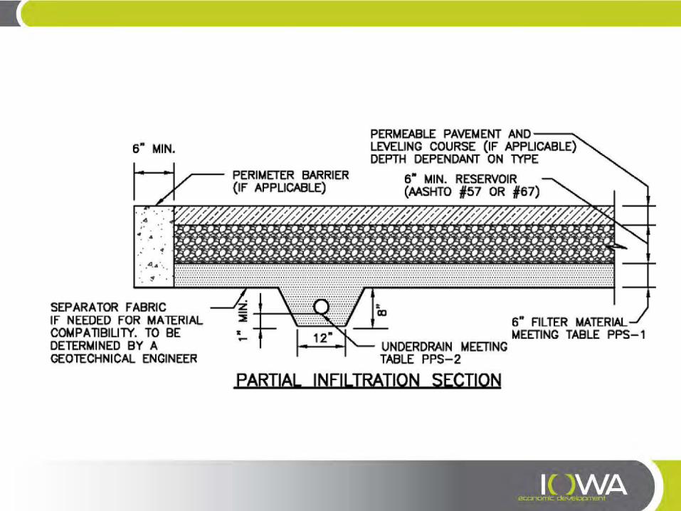
Partial Infiltration Section
No Infiltration Section
Bioretention—Installation & Maintenance » Do not put a filter sock on the underdrain. This is not necessary and can
cause the BMP to clog. » The best surface cover for a rain garden is full vegetation:
– Do not use rock mulch within the rain garden because sediment build-up on rock mulch tends to inhibit infiltration
– Wood mulch floats and may clog the overflow, bury plants or flow downstream. » Consider all potential maintenance requirements such as mowing (if
applicable) and replacement of the growing medium. » Provide pre-treatment when it will reduce the extent and frequency of
maintenance. » Make the rain garden as shallow as possible.
Bioretention—Installation & Maintenance » Protect area from excessive sediment loading during construction. » Avoid over compaction of the area to preserve infiltration rates (for partial
and full infiltration sections). » Provide construction observation to ensure compliance with design
specifications. Improper installation, particularly related to facility dimensions and elevations and underdrain elevations, is a common problem with rain gardens.
» When using an impermeable liner, ensure enough slack in the liner to allow for backfill, compaction, and settling without tearing the liner.
» Provide necessary QA/QC when constructing an impermeable geomembrane liner system.
» Provide adequate construction staking to ensure that the site properly drains into the facility, particularly with respect to surface drainage away from adjacent buildings.
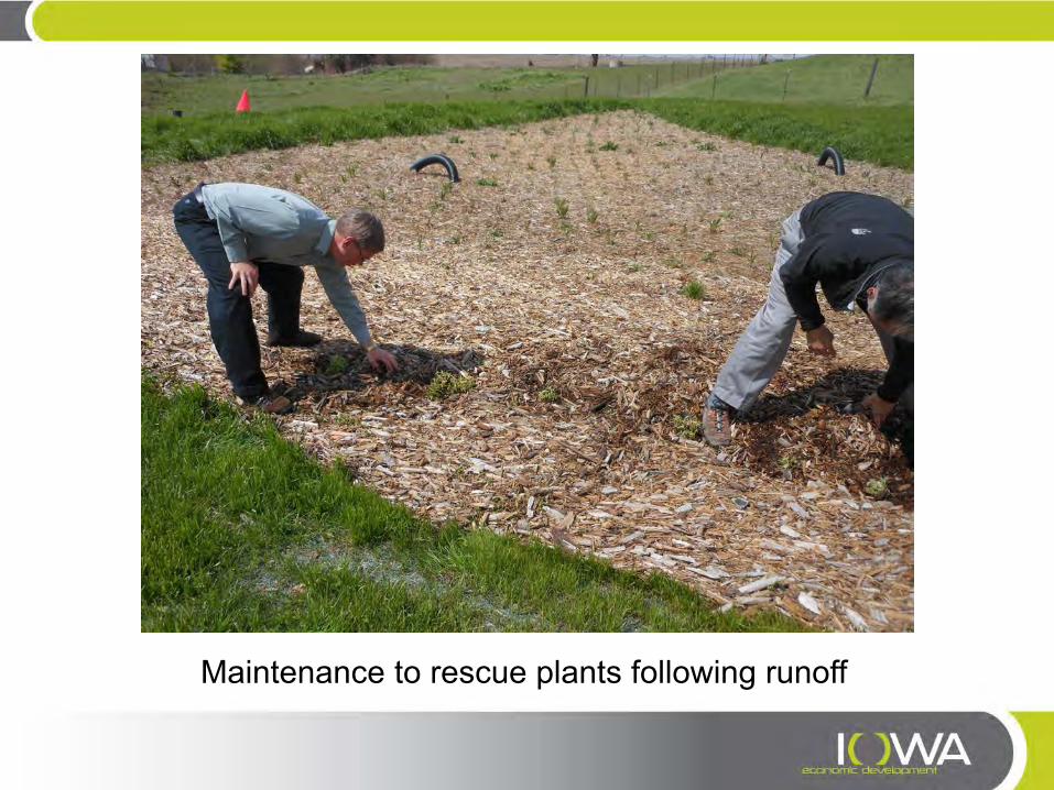
Maintenance to rescue plants following runoff

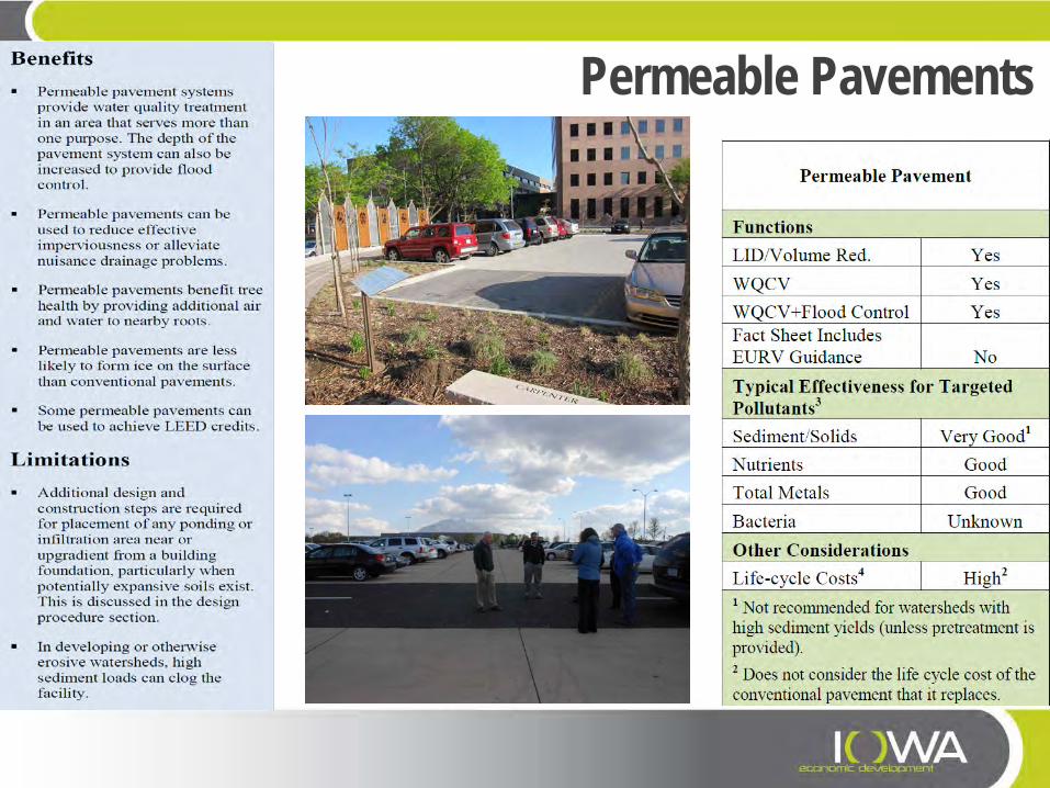
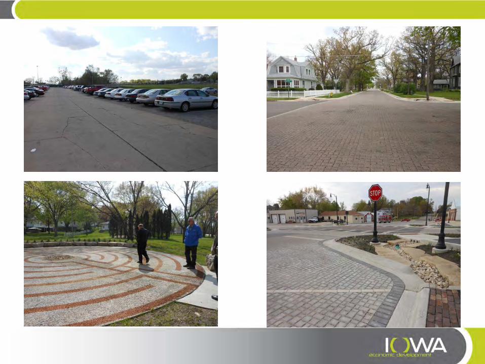
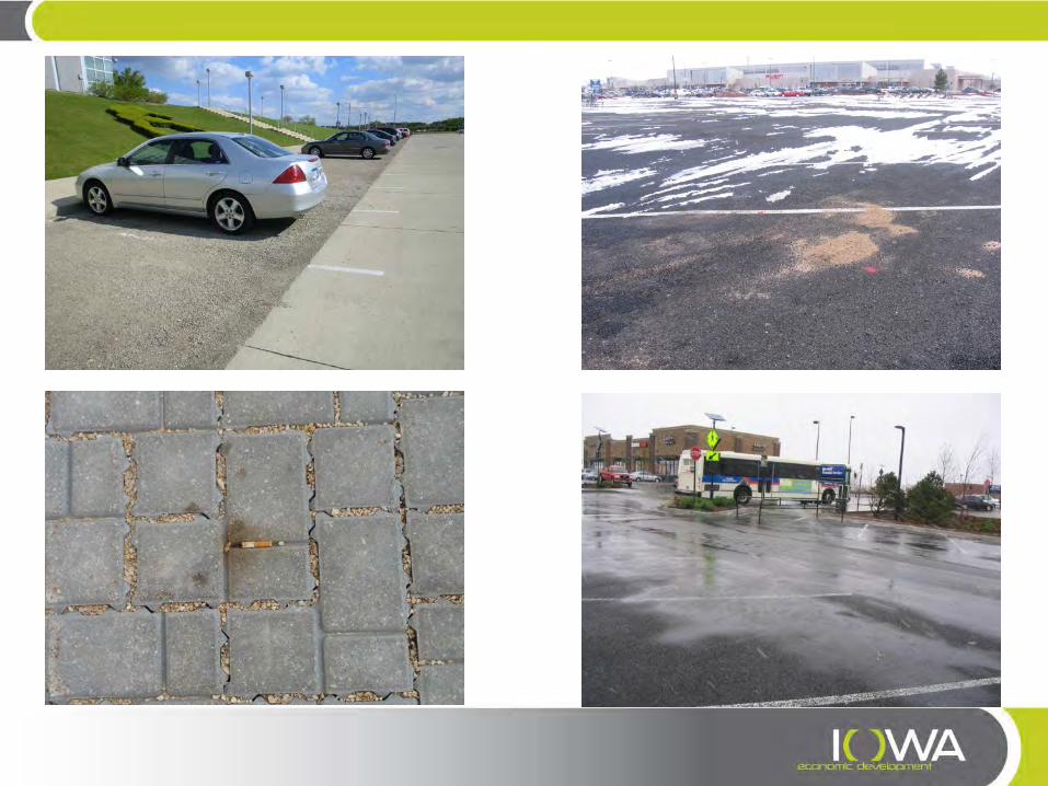
Permeable Pavements
Permeable Pavements
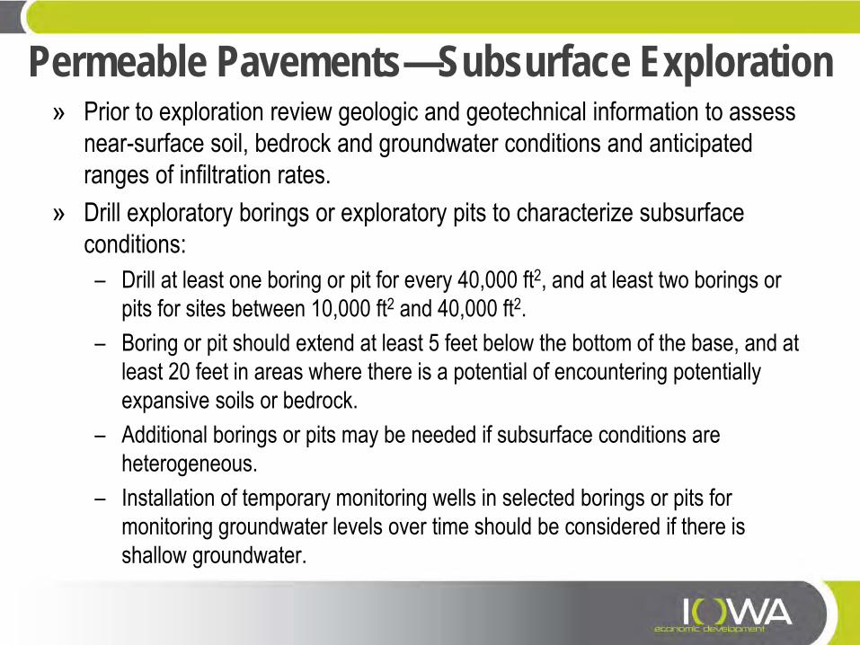
Permeable Pavements—Subsurface Exploration » Prior to exploration review geologic and geotechnical information to assess
near-surface soil, bedrock and groundwater conditions and anticipated ranges of infiltration rates.
» Drill exploratory borings or exploratory pits to characterize subsurface conditions: – Drill at least one boring or pit for every 40,000 ft2, and at least two borings or
pits for sites between 10,000 ft2 and 40,000 ft2. – Boring or pit should extend at least 5 feet below the bottom of the base, and at
least 20 feet in areas where there is a potential of encountering potentially expansive soils or bedrock.
– Additional borings or pits may be needed if subsurface conditions are heterogeneous.
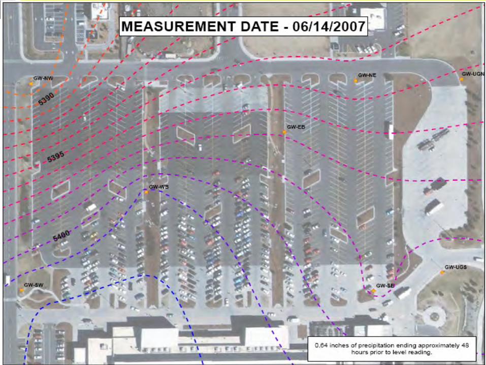
– Installation of temporary monitoring wells in selected borings or pits for monitoring groundwater levels over time should be considered if there is shallow groundwater.
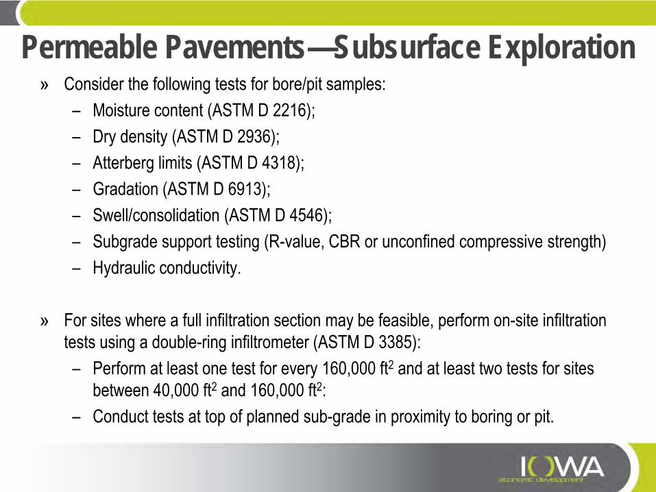
Permeable Pavements—Subsurface Exploration » Consider the following tests for bore/pit samples:
– Moisture content (ASTM D 2216); – Dry density (ASTM D 2936); – Atterberg limits (ASTM D 4318); – Gradation (ASTM D 6913); – Swell/consolidation (ASTM D 4546); – Subgrade support testing (R-value, CBR or unconfined compressive strength) – Hydraulic conductivity.
» For sites where a full infiltration section may be feasible, perform on-site infiltration
tests using a double-ring infiltrometer (ASTM D 3385): – Perform at least one test for every 160,000 ft2 and at least two tests for sites
between 40,000 ft2 and 160,000 ft2: – Conduct tests at top of planned sub-grade in proximity to boring or pit.
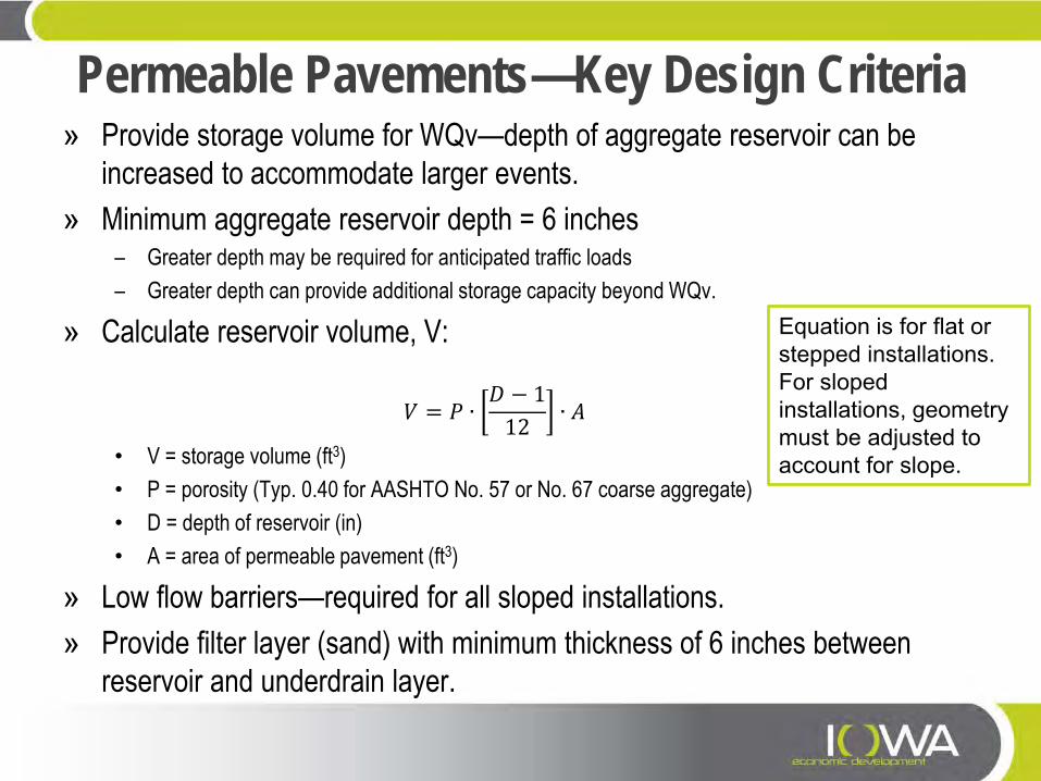
Permeable Pavements—Key Design Criteria » Provide storage volume for WQv—depth of aggregate reservoir can be
increased to accommodate larger events. » Minimum aggregate reservoir depth = 6 inches
– Greater depth may be required for anticipated traffic loads – Greater depth can provide additional storage capacity beyond WQv.
» Calculate reservoir volume, V:
𝑉 = 𝑃 ∙𝐷 − 1
12∙ 𝐴
• V = storage volume (ft3) • P = porosity (Typ. 0.40 for AASHTO No. 57 or No. 67 coarse aggregate) • D = depth of reservoir (in) • A = area of permeable pavement (ft3)
» Low flow barriers—required for all sloped installations. » Provide filter layer (sand) with minimum thickness of 6 inches between
reservoir and underdrain layer.
Equation is for flat or stepped installations. For sloped installations, geometry must be adjusted to account for slope.
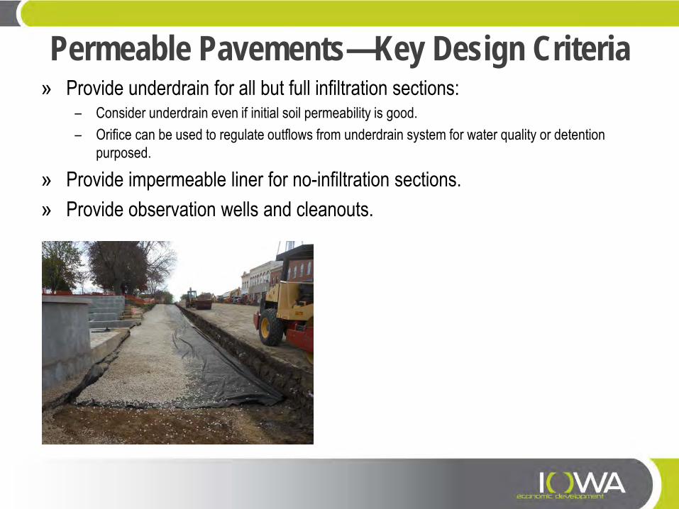
Permeable Pavements—Key Design Criteria » Provide underdrain for all but full infiltration sections:
– Consider underdrain even if initial soil permeability is good. – Orifice can be used to regulate outflows from underdrain system for water quality or detention
purposed.
» Provide impermeable liner for no-infiltration sections. » Provide observation wells and cleanouts.
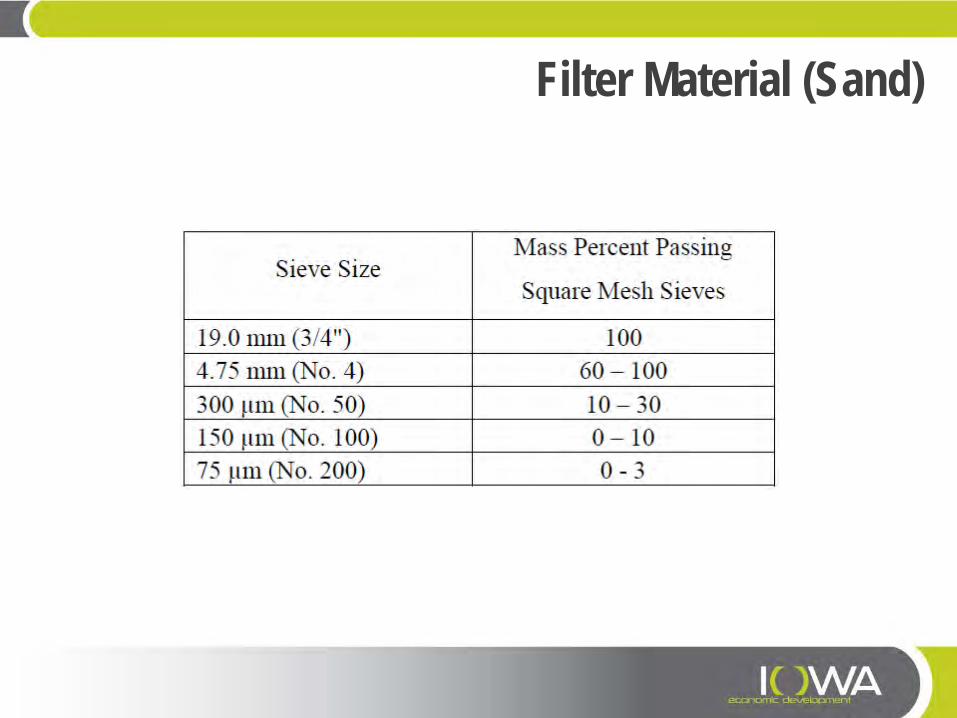
Filter Material (Sand)
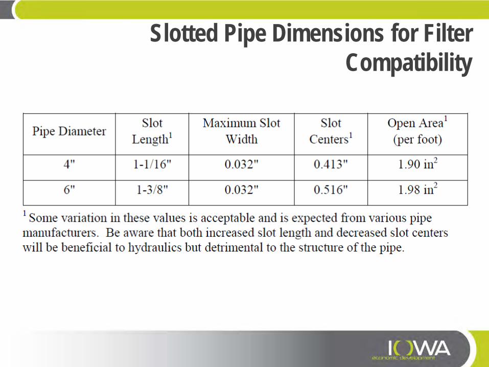
Slotted Pipe Dimensions for Filter Compatibility
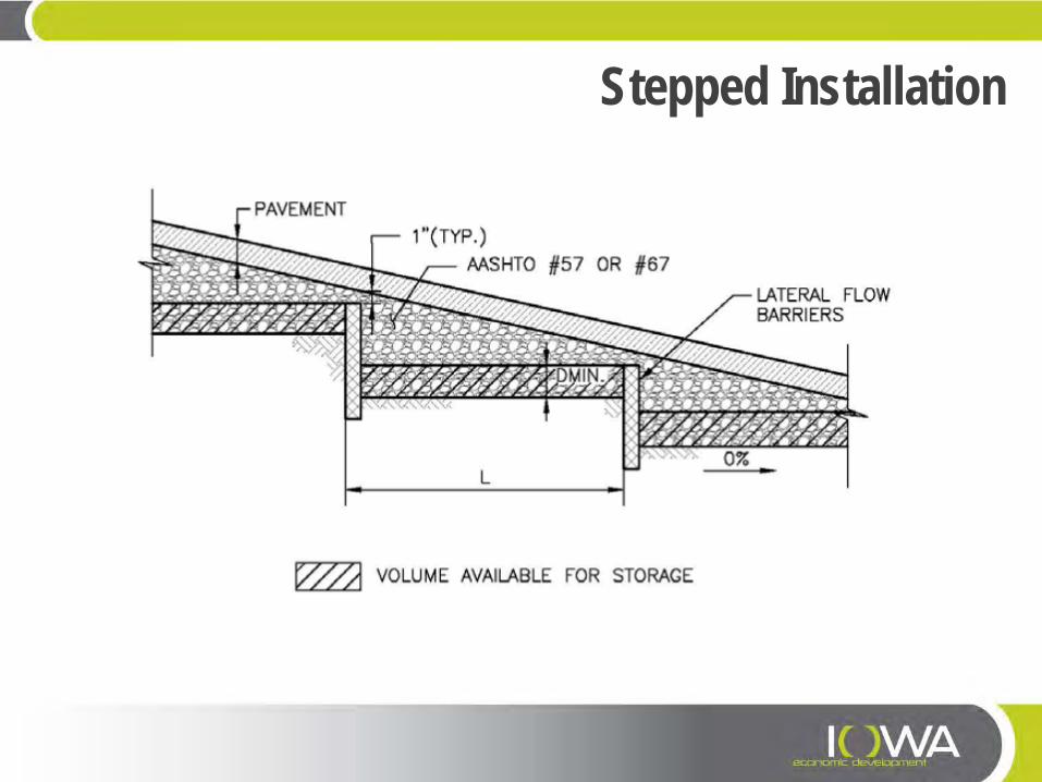
Stepped Installation
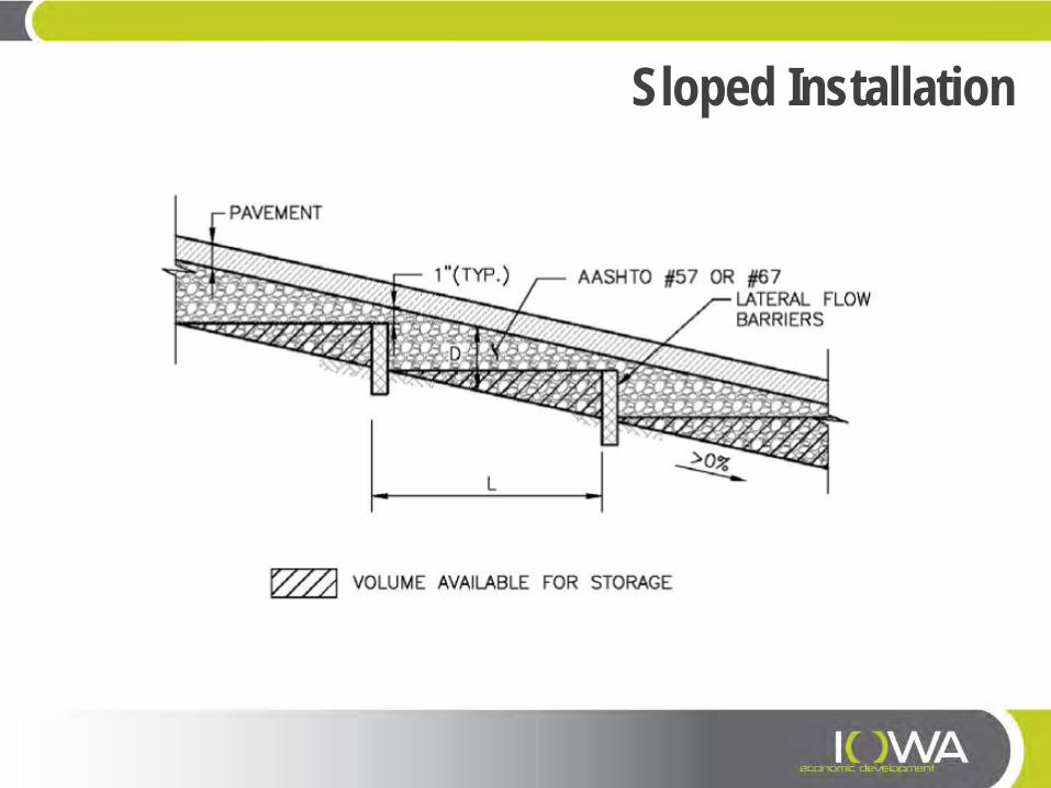
Sloped Installation
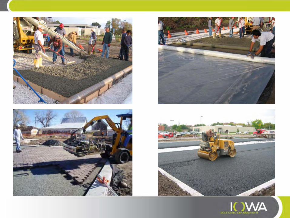
Permeable Pavements—Installation » Hold a pre-construction meeting to ensure that the contactor has an
understanding of how the pavement is intended to function. » Discuss the contractor’s proposed sequence of construction and look for
activities that may require protection of the permeable pavement system. » Ensure that the permeable pavement is protected from construction
activities following pavement construction (e.g., landscaping operations): – Covering pavement – alternative construction vehicle access – education for all parties working onsite.
» Include an observation well to monitor the drain time of the pavement system over time.
» Call for construction fence on the plans around pervious areas where infiltration rates need to be preserved and could be reduced by compaction from construction traffic or storage of materials.
Permeable Pavements—Installation » Subgrade preparation
– Involve a geotechnical engineer who understands permeable pavements! – Compaction may not be needed or may only be needed in “soft” areas, if reservoir is
excavated into sub-grade. – Geogrid and compacted granular fill can be used to bridge “soft” areas. – When final subgrade is placed fill, specify hydraulic conductivity for material to be
placed at least one order of magnitude higher than native material. – Low ground pressure (LGP) track equipment should be used within the pavement area
to limit overcompacting the subgrade. Wheel loads should not be allowed. » Filter layer compaction to a relative density between 70% and 75% (ASTM
D4253 and ASTM D4254) using a walk-behind vibratory roller, vibratory plate compactor or other light compaction equipment.
» Specify reservoir layer compaction using method specification (i.e. type of equipment & number of passes) depending on equipment and depth of layer.

Permeable Concrete Tips » Selection of a contractor with prior experience in successful pervious
concrete installation is highly recommended: – The National Ready Mixed Concrete Association (NRMCA) has a certification program. – It is recommended that at least one out of three workers in the crew performing the
work be certified. » Mixing and transportation of pervious concrete should be completed and
discharged within one hour of the introduction of mixture water to the cement.
– Alternatively, concrete could be mixed on site. – Hydration stabilizer may also be added.
» Compaction of pervious concrete is achieved by rolling, using special equipment:
– Do not over-compact or over-work the concrete. – Cross rolling should be performed using the minimum number of passes required to
achieve an acceptable surface.

Permeable Concrete Tips » Joints should be rolled using a "pizza cutter roller." Joints should never be cut. » Provide expansion material at all isolation/construction joints. » Concrete should be placed spring through fall when the ambient temperature is
between 40° and 90° Fahrenheit. » Mixture water quantity is critical. The correct quantity has been achieved when the
concrete has a wet metallic sheen. » Air entrainment has been shown to increase freeze-thaw durability. » Curing procedures begin immediately, but no later than 20 minutes from the time
pervious concrete is discharged from the truck. – Cover the pavement surface with a 6-mil-thick polyethylene sheet. – The sheet should remain secure and in place until the concrete has reached a maturity
equivalent to 14 days of curing at 70° Fahrenheit at 95% relative humidity. – No vehicular traffic should be permitted during this time.
» Fogging, using a fogging nozzle may be needed to raise the relative humidity of the ambient air over the slab and to reduce evaporation from the concrete.

Permeable Pavement Maintenance » Inspect pavement condition and observe infiltration at least annually, either during a
rain event or with a garden hose to ensure that water infiltrates into the surface. » Debris should be removed, routinely, as a source control measure. » Use a regenerative air or vacuum sweeper after any significant site work (e.g.,
landscaping) and approximately twice per year to maintain infiltration rates. – Conduct sweeping on a warm dry day for best results. – Do not use water with the sweeper. – After vacuuming PICP and Concrete Grid Pavers, replace infill aggregate as needed.
» Plowing is recommended snow removal process. » Do no apply deicers to pervious concrete and use sparingly on pervious asphalt. » Do not sand permeable pavements and consider signage to inform maintenance
crews.