Embed Size (px)
Citation preview

CITY OF HUMBLE
DESIGN CRITERIA MANUAL FOR
WASTEWATER COLLECTION SYSTEMS, WATER LINES, STORM DRAINAGE, AND STREET
PAVING
MARCH 2016

1
TABLE OF CONTENTS
SECTION I – GENERAL REQUIREMENTS ............................................................................................. 2
SECTION II – WASTEWATER COLLECTION SYSTEM DESIGN REQUIREMENTS ........................ 5
SECTION III – WATER LINE DISTRIBUTION SYSTEM DESIGN REQUIREMENTS ..................... 15
SECTION IV – STREET PAVING DESIGN REQUIREMENTS ............................................................ 24
SECTION V – STORM DRAINAGE DESIGN REQUIREMENTS ......................................................... 29
APPENDIX
CITY STANDARD CONSTRUCTION DETAILS

2
SECTION I
GENERAL REQUIREMENTS
1.0 GENERAL
1.01 SECTION INCLUDES:
Graphic requirements for construction drawings and project approval requirements.
1.02 DEFINITIONS
A. CADD (Computer Aided Drafting Design) - the preparation of documents utilizing
computer facilities for the production of drawings, plans, prints and other related
documents.
1.03 DESIGN REQUIREMENTS
A. Provide a cover sheet for all projects involving three or more design drawings (excluding
standard detail sheets). Plan sheet numbers shall be shown on the cover sheet or area key
map. Include a vicinity map to identify project locations. Also provide approval block for
the City Director of Public Works with a note stating that approval is valid for 1 year only
from date of signatures.
B. Drawings shall be prepared on nominal 22 inch x 34 inch overall drawings.
C. Show service area on cover sheet or area map.
D. Final drawings shall be produced by CADD on mylar. The engineer shall also submit, at
the time of plan approval, an electronic CADD and PDF copy of the drawings showing all
lot lines and associated lot information, rights-of-way, easements, contours, utilities, and all
drainage and paving improvements. Two identical reproducibles shall be provided with a
location for an approval signature by the City Director of Public Works on the cover. One
approved set will be returned.
E. Details of special structures (not covered by approved standard drawings, such as stream or
gully crossings, special manholes, or junction boxes, etc.) shall be drawn with vertical and
horizontal scales equal to each other.
F. Each set of construction drawings shall contain paving and utility key drawings indexing
specific plan and profile sheets. Standard City drawings, where applicable, shall be
included. All sheets shall have standard title blocks.
G. Draw key overall layouts to a minimum scale of 1 inch = 100 feet.
H. Plan stationing must run from left to right, except for short streets or lines originating from
a major intersection, where the full length can be shown on one sheet.
I. A north arrow and scale are required on all sheets and should be oriented either toward the
top or to the right. This requirement is waived under the following conditions.
1. A storm or wastewater sewer whose flow is from west to
east or from south to north.
2. A primary outfall ditch drainage facility whose flow is from west to east or from
south to north.
3. It is the intent of this requirement that all stationing should start from the cardinal
points of the compass and proceed in the direction of construction.

3
J. Standard scales permitted for plans and profiles of paving and utility construction drawings
are as follows:
1. Major thoroughfares, streets with esplanades over 400 feet in length, or special
intersections / situations.
1 inch = 20 feet horizontal, 1 inch = 2 feet vertical
2. Minor or residential single-family streets.
1 inch = 20 feet horizontal, 1 inch = 2 feet vertical
3. Scales of Paragraph No. 2 above are minimum; larger scales may be used to
show details of construction.
4. Deviation of specified scales can only be permitted with special approval.
K. Bench mark information will be provided on the project layout sheet along with
information pertaining to traverse points (northing and easting). The benchmark
information to be provided is datum, description of physical location and elevation. In
addition, information pertaining to the design baseline will be provided on project layout
sheet. The provided information to be provided for the design baseline should be beginning
and ending of the baseline (northing and easting) and point of intersection of any line(s)
deviating from 180 along with angle turned right.
L. The seal, date, and original signature of the Licensed Professional Engineer responsible for
the drawings shall be required in each sheet developed by the engineer. The engineer may
use a stamped or embossed imprint for his/her seal; however, the embossed imprint must be
shaded such that it will reproduce on prints.
M. A copy of the final plat for new developments shall be included with the final drawings
when submitted for final approval.
N. If a roadway exists where drawings are being prepared to improve or construct new
pavement or a utility inside the pavement, label the surface type.
O. Show all streets and/or road alignment on drawings.
P. Develop drawings to accurate scale showing proposed pavement, typical cross sections,
details, lines and grade, and all existing topography within street right-of-way, and any
easement contiguous with the right-of-way. At the intersection, the cross street details shall
be shown at sufficient distance (20-foot minimum distance outside the primary roadway
right-of-way) in each direction along cross street for designing adequate street crossings.
Q. Match lines between plan and profile sheets shall not be placed or shown within cross street
intersections including cross street right-of-way.
R. Natural ground profiles shall be shown as follows:
1. For privately-funded projects, center line profiles are satisfactory except where a
difference of 0.50 feet or more exists from one right-of-way or easement line to
the other, in which case, dual profiles are required.
2. For the City of Humble projects, provide natural ground profiles for each right-
of-way line and easement.
S. Basic plan and profile sheets shall contain the following information:
1. Identify all lot lines and property lines (as appropriate for developments and
authorized by the city engineer), easements, right-of-way, and drainage outfalls.

4
2. Label each plan sheet as to street/easement widths, pavement widths, pavement
thickness where applicable, type of roadway materials, curbs, intersection radii,
curve data, stationing, existing utilities (type and location), and any other
pertinent feature affecting design.
3. Show all utility lines four inch or larger within the right-of-way or construction
easement in profile view. Show all utility lines, regardless of size, in the plan
view including fiber optic cables.
4. Graphically, show flow line elevations and direction of flow for all existing
ditches.
5. Label proposed top of curb grades except at railroad crossings. Centerline grades
are acceptable only for paving without curb and gutters.
6. Curb return elevations for turnouts shall show in profiles.
7. The centerline elevation of all existing driveways shall be shown in profile.
8. Station all esplanade noses or the centerline of all esplanade openings with
esplanade width shown - both existing and proposed.
9. The design of both roadways is required on all paving sections with an esplanade.
10. Station all PCs, PTs, radius returns, and grade change PIs in plan view. Station
all radius returns and grade change PIs in profile with their respective elevations.
T. Project Approval Requirements:
1. Upon the completion of construction of the required improvements, the Design
Engineer for the project shall submit a written request for a final inspection of the
project. The letter shall state that he has inspected the improvement and that they
conform to his design plans. An Affidavit stating that all bills have been paid
shall be provided with the inspection request letter. One copy of the “As-Built”
plans along with a copy of the test reports for all required tests shall be included
with the inspection request. An electronic (CADD and PDF) file and a GIS-
compatible update file (if available) of the record drawings shall be provided
prior to acceptance. Once the Final Plat has been recorded, addresses assigned
by the City will be posted to the GIS system.
2. Prior to final acceptance of the project, the developer (or contractor) shall post a
One-Year Maintenance Bond in the amount of 100% of the final construction
costs with the City. This bond shall allow the City to repair any portion of the
project found during the One-Year Warranty period, should the item not be
promptly repaired upon written notification to the bond holder. The One-Year
Warranty period shall commence from the date of Letter of Acceptance issued by
the City.

5
SECTION II
WASTEWATER COLLECTION SYSTEM
DESIGN REQUIREMENTS
2.0 GENERAL
2.01 SECTION INCLUDES:
Criteria for the design of wastewater collection systems.
2.02 REFERENCES:
A. Texas Commission on Environmental Quality - "Design Criteria for Sewer Systems- Texas
Administration Code - Chapter 217 (current revision).
2.03 DEFINITIONS:
This Chapter addresses the design of the wastewater collection systems within the public right-of-
way or a dedicated public easement. Sanitary sewer service lines serving a single building
located on private property, that are not in a dedicated easement, are under the jurisdiction of the
Plumbing Code. Where used in these regulations, the following terms shall be construed to carry
the meanings given below:
A. Public Sewer - A closed conduit that conveys wastewater flow and which is located within
the public right-of-way or dedicated public easement. A public sewer (or public sewer
system) is intended to serve more than one (1) "owner".
B. Private Sewer - A closed conduit that conveys wastewater flow and is constructed and
maintained by a private entity. Private sewers shall be located on private property. Private
sewers are subject to the design and construction requirements of the Plumbing Code.
C. Sewer Main - A sewer that receives the flow from one or more lateral sewers.
D. Lateral Sewer - A sewer running laterally down a street, alley, or easement that receives
only the flow from the abutting property.
E. Service Lead - A sewer that branches off a public sewer and extends to the limits of the
public right-of-way. It shall be construed as having reference to a public sewer branching
off from a main or lateral sewer to serve one or more houses, single-family lots, or other
types of small land tracts situated in the same block with the said main or lateral sewer, but
not directly adjacent thereto. Such a line shall never exceed 150 feet in length. If the sewer
is designed to serve more than two houses, or the equivalent of two single-family
residences along a street, a lateral sewer as defined above shall be constructed.
F. Service Connection - A private sewer from a single source to the main or lateral sewer in
the street, alley, or easement adjacent thereto. Service connections are covered by the
building code. It will be owned and maintained by the owner of the property being served
by said sewer.
G. Project Area - The area within the immediate vicinity of the public sewer to be constructed.
If, as an example, a public sewer is to be constructed within the public right-of-way, the
project area would extend 10 feet to either side of the public right-of-way. If as an
example, a public sewer is to be constructed within a dedicated easement adjacent to the
public right-of-way, the project area would extend 10 feet to either side of the dedicated
easement; depending upon the existing topographical elements, unless impacted by a

6
permanent structure (i.e.. telephone pole, trees, drainage ditches, etc.) If, as an example, a
public sewer is to be constructed within a side lot easement (if approved by the City), the
same criteria would apply as for a dedicated easement adjacent to public right-of-way.
H. Stack - A riser pipe constructed on main or lateral sewers which are deeper than 7 feet to
facilitate construction of service leads or service connections.
I. Force Main - A pressure-rated conduit (i.e. ductile iron pipe, pressure-rated P.V.C., etc.)
that conveys wastewater from a pump station to a discharge point.
J. Pressure sewer systems – A wastewater collection system using a pump at each
residence or customer.
2.04 DESIGN REQUIREMENTS:
A. Obtain approval from the City of Humble for exceptions or deviations from these
requirements. Exceptions or deviations may be granted on a project-by-project basis only.
B. Drawings to be furnished:
Before any main or lateral sewer is constructed and before a permit will be issued for the
construction of same, plans and profiles of the proposed sewer shall be prepared and
submitted by a licensed professional engineer to the City for approval. On projects within
the City limits, the drawing shall become the property of the City and shall remain on file
in the City for the use of any person who may be interested in same.
C. Details to be shown on drawings:
The detailed plan shall will show the exact location of the proposed line in the street, alley
or easement with respect to the edge of the particular right-of-way, the transit base line, and
any nearby utilities, pavement, major landscaping, and other structures affecting
construction.
D. Main and Lateral Sewers:
1. Sewers shall be shown both in detailed plan and profile views. Lines shall
change grade or alignment only at a manhole.
2. The profile shall show other underground and surface utilities and facilities, both
in parallel and at crossings; the size, grade of the proposed line, the elevation of
same to hundredths of a foot at all manholes, changes of grade and dead-ends;
and the proposed finished grade over the sewer (if improvements are requested).
It shall show the actual ground line as it exists prior to construction of the sewer.
Where proposed fill or cut is contemplated, the proposed new ground line shall
be shown as a separate line from the actual ground line. Bedding shall comply
with City of Humble Standard Details. Where the lines are parallel to a ditch the
flow line of the ditch shall be shown.
3. Where sewers are to be placed between existing pavement and the street right-of-
way or under existing pavement, show the existing ground line at both sides (or
the closest side or sewers near the edge) of the right-of-way or adjacent sewer
easement.
4. If there is a drainage ditch or storm sewer between the line and the houses served,
grade shall be shown.

7
E. Sewer mains-plan and profile required:
1. Sanitary sewer layouts for subdivisions shall use a horizontal scale of 1” = 20
feet and vertical scale of 1” = 2 feet.
a. All easements containing or buffering sanitary sewers are shown at
points of size change; all manhole locations are shown.
b. The sewer alignment shall accurately reflect the relative location of the
sewer as shown on the detailed plan view.
c. All service leads that cross street pavement or serve adjacent property are
to be shown on the layout. The detail plans and profiles shall show the
flow lines of all service leads at the street or easement right-of-way.
d. The number and size of the lots depicted on both the overall sewer layout
sheet and the individual plan and profile sheets shall match the number
and size of the lots depicted on the final plat after recordation.
e. On the overall sanitary sewer layout sheet the size and direction of flow
for all existing and proposed sewers shall be shown.
f. The location of the proposed sewer within either the public right-of-way,
a dedicated easement adjacent to the public right-of-way, or side lot
easement (if allowed by the City).
g. The overall sanitary sewer layout sheet shall show the area, in acres,
which the proposed sewer(s) is (are) designed to serve. Include a
location map that references the distance to nearby major thoroughfare
and boulevard streets. The scale of the location map shall be 1 inch =
1,000 feet or less.
2. The plan view shall show, at a minimum, the following information for the
project area:
a. All topographical features;
b. Stationing for the proposed sewers;
c. All existing and proposed utilities (i.e., water, gas, power, etc.);
d. Any significant landscaping and/or other structures which might impact
construction and/or construction related activities;
e. The width and type of all existing and proposed easements;
f. All proposed service leads;
g. The limits of bore and/or tunnel;
h. Drawings for subdivisions shall show the proposed location, by stations,
of all service leads, service connections, and stacks. The distance from
the sewer to the nearest existing manhole shall be shown in the plan view
or on an additional sewer layout sheet with a scale no more than 1 inch =
100 feet;
3. The profile view shall show, at a minimum, the following information for the
project area:
a. Underground and/or surface utilities/facilities, which are either parallel
to the proposed sewer or cross the proposed sewers;
b. The proposed sewer's diameter and grade for each manhole section;
c. The flow line elevation for all sanitary sewers at each manhole;
d. The rim elevation of all existing and proposed manholes;
The 100 year flood elevations where applicable with bolt down manhole
lids and inflow prevents when below the 100 year flood elevation.
e. The flow line elevation at each sheet "break" (i.e., from one sheet to
another);
f. Type of pipe bedding/backfill shall be noted on each plan/profile sheet;

8
g. The finished grade for proposed and existing pavement where "fill"
and/or "cut" is proposed, the proposed new ground line should be shown
as a separate line from the existing ground line;
h. The existing ground line for the "near side" of the public right-of-way
where a sewer is to be placed between the edge of existing pavement and
the edge of the public right-of-way;
i. The existing ground line at the centerline of the proposed sanitary sewer
where a sanitary sewer where a sanitary sewer is to be placed within an
existing easement. Show any proposed and/or existing pavement.
j. The flow line elevation of all service leads where same crosses the edge
of the public right-of-way or the dedicated easement adjacent to the
public right-of-way, stacks shall be required when over 7’ deep
k. The limits of bore and/or tunnel;
l. Locations where pressure pipe to be installed for water line crossings;
m. The location of special backfill and/or proposed stacks shall be identified
by "stations" indicated on the design plans.
n. Crossing utility lines and storm sewers and parallel drainage facilities.
F. Service leads:
1. Service leads shall be at the property line between two (2) adjoining lots, or as
directed by the City. A single 6-inch service lead located at the property line
between two (2) adjoining lots may serve two (2) single-family residences with a
wye placed at the end of the service lead. Do not extend the wye clean-outs
beyond the edge of either the public right-of-way or dedicated easement.
2. Any service lead extension of more than 50 feet parallel to the street right-of-way
shall be treated as a lateral sewer.
3. Service leads from developments with more than 17,500 gallons-per-day flow
shall discharge into a proposed or existing manhole. Where the flow line is 24
inches or greater above the flow line of the manhole, provide a standard drop to
manhole. Service shall conform to the following:
a. Service leads shall be provided to serve each lot within the proposed
development.
b. Service leads shall utilize "full body" fitting (extruded or factory-
fabricated) for connection to the proposed public sewer. An approved
saddle-type connector for connection to an existing public sewer may be
used, but not for proposed lines.
c. Saddle-type connectors shall be installed with the "stub" oriented
between the "spring line" (3 o'clock and 9 o'clock positions) and 45
degrees from the "spring line" ("1:30" and "10:30" positions). These
type of connections will only be allowed for new service taps on existing
sanitary sewers. Tees (aka, "full body fittings") shall be oriented in the
same manner.
d. The service lead shall be designated to minimize the use of bends as site
conditions will permit.
e. Stacks shall be provided where the services are over 7 feet deep.
f. Each service end shall be marked for easy future excavations.
g. Each service shall have a cleanout within 2 feet of the property line.

9
G. General Requirements:
1. Sanitary sewers within the City of Humble shall allow for orderly expansion of
the system and shall conform to the wastewater master plan for the City of
Humble.
2. Sewers shall be sized based on the minimum requirements set out in this standard
and the standard wastewater flow rates as established by the City.
3. All sewers shall conform to the minimum requirements of the Texas Commission
on Environmental Quality Chapter 217– “Design Criteria for Sewage Systems”.
4. Sewers shall be separated from water lines by a minimum of nine (9) feet.
Where the minimum separation is not maintained, refer to Section 3 for
allowable clearances. Sewers crossing utilities other than water, a minimum of
six (6) inches of clearance shall be maintained.
5. Place stacks and wyes or tees as shown. Where no stacks are shown, it is the
responsibility of the licensed plumber to place a City approved saddle for
connection to the line.
6. All lines and manholes shall be tested in accordance with TCEQ regulations.
7. Unless noted otherwise, all public sewers and service leads shall be embedded in
cement stabilized sand as per latest City of Humble Standard Details. All such
bedding shall be compacted to 95% standard proctor density. The cross-section
so described herein shall be termed the "embedment zone."
8. Backfill all excavation areas/trenches under or within 2-feet of existing or
proposed pavement with cement-stabilized sand from the top of the pipe
"embedment zone" up to 1-foot below paving sub-grade. Cement-stabilized sand
with a minimum cement content of 1.5 sacks per cubic yard must develop 100-
psi compressive strength at 48 hours. Backfill shall be compacted to 95%
standard proctor density.
9. The location of all special backfill and of proposed stacks shall be shown by
stations in the drawings.
10. Construction notes shall designate the type, kind and class of pipe with
exceptions to the construction notes to be shown on the plan and profile sheets.
11. Non-sanitary sewer easements or fee strips such as pipeline, power company,
drainage district, railroad, etc., are in and of themselves insufficient and
unacceptable to permit laying to sanitary sewers and/or force mains across or
along the underlying private property or restricted non-sanitary use type of public
property.
12. The final determination as to that portion of a street, alley, or easement to be
occupied by a proposed sewer rests within the City. The Director will take into
consideration existing, planned and proposed facilities such as manholes,
pavement, pipe/conduits, along with existing trees, shrubs, or other unique
surface conditions when arriving at a decision.
13. Where an easement for a public sewer ends at a public right-of-way, the last
manhole shall be extended into the public right-of-way as a minimum of 2 feet
beyond the property line; or as close to the public right-of-way as possible due to
acceptable clearances required for other utilities (i.e., water line and storm
sewers).
14. The drawings for the sewer shall show the location of any existing known pipe or
duct that might interfere with the construction of the sewer and call to the
attention of the City any known obstacles that might be encountered in
constructing the sewer in any location under consideration. The Professional
Engineer shall determine the existence of pipes, ducts and/or obstacles from a
visual survey on the ground plus research of all public records and private
records when available.

10
15. All gravity sanitary sewer mains under 12 feet of depth shall be constructed
utilizing, SDR 26, PVC. Force mains shall be SDR 26 Class 160 PVC pipe.
16. Where a sanitary sewer line could be extended to serve an adjacent development,
the public sewers main shall be extended across the full length of the
development or to the edge of the property where streets may be extended.
H. Line Size:
1. The minimum pipe diameter for a public sanitary sewer shall be 8 inches.
2. Six inch service leads shall be confined to the limits of the lot, which they serve
and shall serve only the equivalent of one single-family lot. No 6-inch sewer
shall be laid in any street, alley, or right-of-way.
3. Six-inch service leads shall not serve more than the equivalent of two single-
family lots or other types of small land tracts.
4. Six-inch service leads for single-family residential lots shall have a minimum
grade of 0.70 percent.
5. For commercial service leads such as street bores, submit a copy of the approved
plumbing drawings to establish the required size of the line. The minimum size
lead shall be 6 inches.
6. All main and lateral sewers will end in manholes, except for special and/or
unusual situations and subject to specific approval of same.
7. All sewer lines shall be laid at a size and depth to conform to designs permitting
an orderly expansion of the sewer system of the City and so as to avoid a
duplication of lines in the future.
8. The City shall be the final judge as to sizes and depths required and exceptions to
"lateral service leads" as previously defined.
I. Line Depth:
1. The sewer shall be laid with the top of the pipe a minimum of 3 feet below
finished grade or top of curb, whichever is lower. In areas with open ditches, the
lines and leads shall be 2 feet below the flow line of the ditches or specific
approval obtained and special protection provided.
2. Sewer laid in street rights-of-way with curb and gutter paved streets shall have a
minimum cover of 4 feet from the top of the pipe to the top of the curb to
anticipate future sewer extension.
3. Sewers laid in street right-of-way with crowned roads and side ditches shall have
a minimum cover of 5 feet from the average ground line at the adjacent street
right-of-way to the top of pipe.
4. Where the minimum cover as specified in paragraphs I, 1,2, and 3 above is not
possible, the sewer shall be laid in Class 150 (150 psi) pressure pipe or rigid
factory made pipe with cement stabilized sand as shown in standard detail.
Ductile iron pipe shall be lined with either a polyethylene or polyurethane
coating as approved by the pipe manufacturer and applied by either the pipe
manufacturer or an approved application. The minimum liner thickness shall be
40 mil.

11
J. Line Grades.
1. The following table lists the minimum grades for 6-27 inch public sewers.
Inside Dimension (I.D.)
of Pipe in Inches Minimum Slope
6 0.50
8 0.33
10 0.25
12 0.20
15 0.15
18 0.11
21 0.09
24 0.08
27 0.06
For sewers larger than 27 inches in diameter, the Professional Engineer of record
shall determine the appropriate grade utilizing the Manning Formula, n = 0.013
and a full pipe velocity of 2.0 fps.
K. Manholes:
1. All manholes shall be pre-cast concrete, unless the Professional Engineer submits
a "cast in place" manhole design for review and approved by the City. All pre-
cast manholes shall incorporate a "boot" type connector for sewer diameters up to
24 inch. For sewer diameters greater than 24 inches, utilize either the "boot" type
connector (if available) or an integral gasket. All pre-cast manholes shall
conform to the latest ASTM requirements.
2. For all public sewers, manholes shall be placed at all changes in alignment,
changes in grade, junction points, and either at street, alley, or easement
intersections as designs may require.
a. Sewers laid in easements shall have a manhole in each street crossed by
the sewer.
b. The maximum distance between manholes shall be 500 feet for 8 inch to
48-inch pipe diameters. Spacings for larger diameter mains than 48
inches shall be determined on an individual project basis.
c. Sewers with the same, or approximate flow line elevation shall intersect
each other at a 90-degree or greater angle. However, where a true
perpendicular intersection cannot be obtained, and where the "entering"
sewer intersects the receiving sewer at, or about, the same flow line, one
or more manholes shall be utilized to maintain a minimum angle of 80
degrees at the point of intersection. Inverts shall be shaped to gentle
curves and have a depth not less than 70% of the pipe diameter. Abrupt
changes in alignment at pipe entrances that limit access of TV inspection
will not be accepted.
(1) A distinct flow channel can be maintained within the manhole
when the flowline elevations of the sewers are at, or within, one
(1) pipe diameter of the smaller pipe; or
(2) Manholes shall be placed at all dead-end mains and laterals.
d. Criteria for connections to, and utilization of, manholes.

12
(1) Where manholes are utilized to facilitate connections between
public sewers, when possible the sewers shall either match the
manhole's flow line, match the elevation of each other's crown or
utilize and "outside" manhole drop.
(2) Connections between public sewers at the manhole shall adhere
to the following criteria when possible:
(a) The elevation of the crown of the discharging sewer
shall either match the elevation of the crown of the
receiving sewer or be approved as special cases by the
City.
(b) A standard drop connection is required when the
difference in elevation between discharging sewer
flowline and receiving flowline is greater than 24 inches.
(3) The routing of service connection directly to manholes will be
allowed only where the flowline elevation of the existing
sanitary sewer is more than 10 feet below grade.
(4) When routing an approved service connection to a manhole (see
Item "3"), the wall penetration shall not be greater than 10 inches
in diameter and shall be cored and sealed using nonshrink grout.
A pipe gasket shall be embedded in the grout.
(5) When routing an approved service connection to a manhole (see
Item "3"), the connections shall utilize a "drop and shall adhere
to the following criteria:
(a) The manhole wall penetration shall be a minimum of 10
feet below the manhole rim elevation and shall not be
greater than 10 inches in diameter;
(b) The drop shall be 6 inches in diameter and shall be
constructed of SDR 26 PVC pipe (ATSM D 3034-94);
(c) The drop shall be located 45 degrees from the upstream
side of the main sewer;
(d) The wall penetration (core) shall be sealed using a
"grout" as approved by the City.
(6) All public sewers shall terminate in a manhole. Clean-outs will
not be utilized.
(7) All sewer lines shall be air tested for leakage. Lines shall have
deflection. Tests conducted a minimum of 30 days after
installation and all manholes shall be vacuum tested. All tests
shall be in accordance with Chapter 217 of TCEQ rules.
L. Lift Stations:
1. Lift station design shall comply with the City of Humble specifications, with a
storage minimum volume (pump on to pump off) in the wet well equal to design
flow (in gallons per minutes) multiplied by 0.25 multiplied by 15 minutes.
2. Minimum site size shall be 30 feet by 30 feet. Odor control measures shall be
considered on an individual basis.
3. Pumps shall be sized to operate at optimum efficiency. Minimum acceptable
efficiency at the operating point shall be sixty percent (60%) unless specifically
approved by the City. Only submersible pumps will be accepted.
4. Operation and maintenance shall be considered in the design of the station and
the location of the station.
5. Wet well working volume shall be sized to allow for the maximum of 4 starts per
hour with one pump out of service.
6. Controls and equipment shall be approved by the Department of Public Works.

13
7. Emergency operations shall be considered. Provide fittings and a blind flange
that will be readily accessible for emergency bypass pumping and connector for a
portable generator. A manhole shall be installed within 10 feet upstream of the
wet well to provide an access point for bypass pumping.
8. The inlet structure shall be designed to minimize turbulence.
9. The velocity in the Force Main and riser pipes shall be less than 6 fps and greater
than 3 fps.
10. The wet well shall be sized to provide adequate clearance between the pumps
(refer to manufacturers recommended clearances).
11. A peak factor of four (4) shall be used for Lift Station design.
12. A minimum of two (2) feet of clearance shall be provided between pumps and
between pump and wall, or as required by the pump manufacturer.
13. Low water level shall be at least six (6) inches above impeller; higher if required
by manufacturer. Complete immersion of submersible pump motor at low water
level is preferred.
14. Tie steel in Lift Station bottom to wall (includes caisson construction situation) to
provide watertight wet well.
15. Nuts, bolts, chains and all other metal components within wet well shall be
stainless steel, not carbon steel.
16. Vent pipe shall be eight (8) inches minimum diameter.
17. The following Hazen-Williams Coefficient shall be used for various pipe types:
PVC New C = 140
10-year C = 130
DIP New C = 130
10-year C = 100
18. Provide board fence (either CCA cedar or heart redwood) with steel posts in
concrete. Fence shall be at least six (6) foot high.
19. Entrance drive to be at least fourteen (14) feet wide. Drive shall terminate
adjacent to the station with a parking space such that a truck-mounted hoist can
remove pumps.
20. Indicate method of drainage of site on site plan. Internal drainage, sheet flow and
valley gutter driveways are acceptable. Drain to street or storm sewer, never
onto adjacent private property.
21. Locate control panel and wet well hatch 1 foot above 100-year flood plain
minimum. Call out the 100-year flood plain elevation on the plans.
22. Dual stainless steel guide rails (or other pump removal method that avoids
entering wet well) are required for submersible pumps. Size and spacing shall be
approved.
23. A tee, plug valve and blind flange assembly is required on the force main on the
downstream side of the discharge valves and header. This is required so truck-
mounted pumps can bypass the lift station pumps and piping while work is being
done.
24. Bedding for PVC force main shall be bank sand as per the latest City of Humble
Standard Details.
25. PVC force mains shall be SDR 26 (ASTM 2241) Class 160 PVC pipe (green
color).
26. Backfill structural excavations (wet well, etc.) with cement stabilized sand.
27. Lift station site plans shall be submitted in scales of 1-inch = 5-feet or 1-inch =
10-feet.
28. Provide a protective coating to interior walls of wet well. Minimum 100 mils of
Raven 405 Epoxy Liner.
29. Lift station shall be equipped with City approved SCADA equipment and
connected to the City’s SCADA system to monitor and operate the lift station
remotely.
30. Power supply to lift station shall be 3 phase (and 480 volts where possible).

14
31. A system of floats or Department of Public Works approved transducer system
shall be provided to control pumps.
32. Lift station shall be equipped with a Godwin natural gas, self-priming standby
pump, sized to meet the capacity of the lift station.
2.05 SUBMITTALS:
A. Preliminary design - submit the following for review and comment:
1. Copies of any documents that show approval of exceptions to the City design
criteria.
2. Design calculations for line sizes and grades.
3. Contour map for overall area.
4. Plan and profile sheets showing proposed improvements
5. Geotechnical soils report for the project (City projects only).
B. Final design - submit the following for approval:
1. Final documents of the above plus plan and profile sheets and Geotechnical soils
reports for non-City projects.
2. Review prints.
3. Original drawings.
C. Final acceptance – submit the following for approval:
1. As – Built plans with a letter from the design engineer stating that the project was
constructed in conformance with the plans.
2. Line pressure and mandrel test results.
3. Manhole vacuum test results.
4. Television inspection reports and videos.
5. Request physical inspection by city staff.
6. One-Year Maintenance Bond valid for one year from the date of acceptance by
the City.
2.06 QUALITY ASSURANCE:
Prepare calculations and construction drawings under the supervision of a Professional Engineer
trained and Licensed under the disciplines required by the drawings. The final construction
drawings must be sealed, signed, and dated by the Professional Engineer responsible for the
development of the drawings.

15
SECTION III
WATER LINE DISTRIBUTION SYSTEM
DESIGN REQUIREMENTS
3.0 GENERAL
3.01 SECTION INCLUDES:
Criteria for the design of water line distribution systems.
3.02 REFERENCES:
A. TCEQ, Water Utilities Division "Rules and Regulations for Public Water Systems," latest
revision.
B. American Water Works Association (AWWA).
C. National Sanitation Foundation (NSF).
D. Texas Department of Health.
E. Texas State Board of Insurance.
3.03 DEFINITIONS:
A. Water Line - Closed conduits designed to distribute potable water for human consumption
to various areas and provide fire protection. Line size and fire protection accessory
locations are dependent on distance from primary source and quantity of demand.
3.04 DESIGN REQUIREMENTS:
A. Obtain approval from the City of Humble for exceptions or deviations from these
requirements. Exceptions or deviations may be granted on a project-by-project basis only.
B. Easements for water lines:
1. Lines shall be located within street right-of-way, permanent access easements with
overlapping public utility easements, easements adjacent to street rights-of way or
recorded water line easements.
2. When outside of a public street right-of-way or permanent access easement with an
overlapping public utility easement, easements must be dedicated.
3. When possible, easements should be contiguous with public rights-of-way.
4. Except for side lot easements, water line easements shall be contiguous to a paved
access.
5. For water lines located adjacent to street rights-of-way, the minimum width of
easement shall be 10 feet.
6. For water lines 16 inches or larger located outside of street rights-of-way, the
minimum width of easement shall be 15 feet.
7. For water mains located less than 5 feet from the right-of-way line, the outside edge
of a water line easement shall be located from the right-of-way line as follows:
14 inch and smaller pipe - 5 feet.
16 inch and larger pipe - 10 feet
8. Water lines along State rights-of-way shall be installed outside of the right-of-way in
a separate 10-foot minimum contiguous easement. If additional utilities are
anticipated in the easement additional width shall be provided.
9. No back lot easements will be allowed for the installation of water lines.

16
10. Commercial Developments inside the City requiring on-site fire hydrants must
provide a minimum 15-foot water line easement for the water line and fire hydrant.
11. In new developments, water lines shall be centered in water line easements.
12. When using side lot easements, such easements shall be a minimum of 15 feet in
width, located on one lot or centered between lots. Water line shall not be closer than
5 feet from an easement edge.
13. Location of a water main in an easement not adjoining a public right-of-way shall be
prohibited, except as specifically approved by the Director. When approved, these
water mains will be centered in a 15-foot wide exclusive easement.
C. Location of water lines:
1. Locate within a street right-of-way.
2. Location of waterlines within an easement - locate waterlines in the center of a 10-
foot minimum width dedicated waterline easement. Obtain approval for lines to be
located in wider or multi-use easements.
3. When a water line is placed parallel to another utility line, or storm sewer other than
a sanitary sewer, the water line shall have a minimum of 4 feet horizontal clearance
from outside wall of the water line to the outside wall of the existing utility or storm
sewer.
D. Water line size:
1. 6 inch lines may be used on dead-end lines within cul-de-sacs or if the line is less
than 1,000 feet in length and interconnected between two lines which are 8 inches in
size or larger. The maximum number of fire hydrants or flushing valves on a dead
end line is one. One hydrant will be permitted on a looped 6-inch line.
2. 8-inch lines may be used for lines over 1,000 feet long or when 2 or more fire
hydrants or flushing valves are required.
3. In areas anticipating commercial development, the minimum line sizes shall be 8
inches or larger based on anticipated required fire flows in accordance with Insurance
Service Office (ISO) requirements.
4. 12 inch and larger lines - lines to be determined by the Professional Engineer (P.E.)
and City of Humble.
5. All systems shall be designed to provide a minimum of 1,000 gallons per minute fire
flow for a minimum of 2 hours.
E. Dead-end lines:
1. Dead-end lines within a public right-of-way.
a. On permanent dead-ends, other than cul-de-sacs, the line shall be 6 inches and
shall not exceed more than 500 feet in length from the closest interconnection
main line and shall terminate with a fire hydrant or automatic flush valve.
b. In permanent dead-end situations within cul-de-sacs, reduce pipe size
successively. Carry 8 inch pipe to the next to last hydrant, then use 6 inch pipe
to the line's end. Place the last service as near as possible to the end and install
a fire hydrant at the end of the 6 inch line. The maximum length of this
reduced line size configuration should not exceed 500 feet. 4-inch lines may
be used on dead-end lines within cul-de-sacs supplying a maximum of 16 lots
provided all structures are within a 250 feet of a fire hydrant. For this carry 6-
inch pipe to the last hydrant then use 4-inch pipe to the line’s end. Place the
last service as near as possible to the end and install a standard 2-inch
automatic flush valve at the end of the 4-inch line.

17
F. Depth of cover:
1. 14 inch and smaller mains shall have a minimum cover of 4 feet from top of curb.
For open ditch roadway sections, 12 inch and smaller shall be installed at least 3 feet
below the ultimate flowline of the ditch or 6 feet below natural ground at the right-of-
way line, whichever is deeper.
2. 16 inch and larger mains shall have a minimum cover of 5 feet from top of curb. For
open ditch roadway sections, 16 inch and longer mains shall be installed at least 4
feet below the flow line of the ditch or 7 feet below natural ground at the right-of-
way line, whichever is deeper.
G. Water line crossings:
1. Public and private utility crossings other than sanitary sewer.
a. Where a water line crosses another utility other than a sanitary sewer, a
minimum of 6 inches of clearance must be maintained between the outside wall
of the water line and the outside wall of the utility.
2. Stream and Ditch Crossings
a. Elevated crossings:
(1) All water lines shall be welded steel or flanged ductile iron pipe and shall
extend a minimum of 15 feet beyond the last bend or to the right-of-way
line, whichever is greater.
(2) Elevated crossings are preferred to underground crossings.
(3) Use a separate elevated supporting structure for 16 inch and larger water
lines unless otherwise approved by the City. Locate the structure a
minimum of 10 feet from any existing or proposed structure.
(4) Support water lines on existing or proposed bridges meeting the
following criteria may be used for 12 inch and smaller lines when
approved in advance by the City.
(a) Have adequate structural capacity.
(b) Have sufficient clearance above the bent cap elevation for
installation under the bridge.
(5) Design elevated crossings with the elevation of the bottom of the water
line above the low chord of the nearest adjacent bridge or a minimum of
1 ½ feet above the 100 year flood plain elevation, whichever is higher.
(6) Extend pipe from right-of-way to right-of-way for crossings.
(7) Provide sufficient span length to accommodate the cross section of future
widening of the stream or ditch, if available.
(8) Support the line on columns spaced to accommodate the structural
capacity of the pipe considering deflection and loading.
(9) Base column support design on soil capacity, spacing, loading, and
structural requirements.
(10) Piers are not allowed in the center of the stream.
b. Underground crossings:
(1) Provide a minimum 5-foot clearance above the top of the pipe to the
ultimate flow line of the ditch.
(2) Provide sufficient length to exceed the ultimate future development of
the stream or ditch.
(3) All water lines shall be welded steel or restrained joint pipe and shall
extend a minimum of 15 feet beyond the last bend or to the right-of-way,
whichever is greater and have valves located on both sides of the
crossing.
H. State highway and county road crossings:

18
1. Extend carrier pipe from flow-line to flow-line for open ditch sections and 5’ behind
back of curb for curb and gutter sections.
2. State highway crossings shall be constructed in conformance with the requirements
of the Texas Department of Transportation (TxDOT) and shall be permitted by
TxDOT.
3. When additional right-of-way has been acquired or will be required for future
widening, the casing, where required, should be coordinated with the appropriate
agency.
I. Street crossings:
1. All water mains and sprinkler line crossings under major arterial thoroughfares and
major regional thoroughfares shall be encased using a minimum of PVC pipe, SDR
21 or steel pipe.
2. Crossings under existing concrete streets shall be installed by trenchless construction.
Water may be used to facilitate boring operations. Jetting the pipe main into place
will not be permitted. When conditions exist that warrant open cut across and
existing street, the Department of Public Works shall specifically approve the
crossing.
3. All open cut installations under existing or proposed streets shall be backfilled as
shown in the City of Humble Standard Details.
4. All street crossings shall be constructed in accordance with construction plans
approved by the City. All street crossings shall be inspected by the City or its
designated representative. All street crossings shall meet the requirements of these
standards.
J. Oil and gas pipeline crossings:
1. Do not use metallic pipe when crossing oil or gas transmission lines unless a properly
designed cathodic system is implemented with City approval. Other pipe may be
used, regardless of depth, subject to approval by the City. Maintain a minimum 2
foot separation between the pipeline and waterline. All required permits and
correspondence with the pipeline company is to be done by engineer, not City
personnel.
K. On-site fire loops within commercial and multi-family developments.
1. For commercial and multi-family developments inside the City requiring on-site fire
hydrants, comply with the following requirements to allow maintenance and future
repair operations.
a. Do not allow placement of structures, equipment pads over the easement.
b. Provide 10 foot wide longitudinal pavement joint along easement lines
where the water line is located under driveway or street pavement.
L. Additional requirements: Pipe shall be C900 or C905 (DR 18) Class 235 PVC pipe
conforming to AWWA requirements with integral bells.
M. Auger (bore) construction:
1. Use the following general criteria for establishing auger or bore sections:
a. Auger or bore sections shall be clearly shown on drawings.
b. Improved streets - use auger construction to cross the street regardless of
surface. Auger length shall be computed as roadway width at proposed bore
location plus 5 feet to either side of the roadway, where applicable.
19
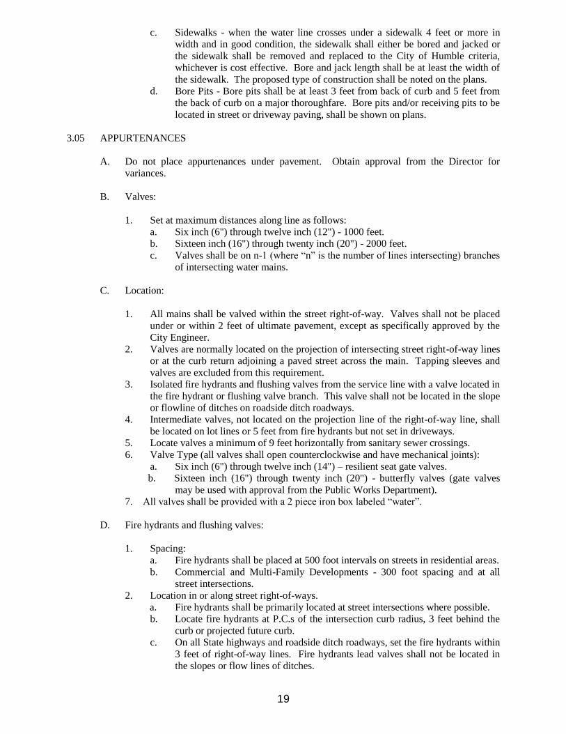
c. Sidewalks - when the water line crosses under a sidewalk 4 feet or more in
width and in good condition, the sidewalk shall either be bored and jacked or
the sidewalk shall be removed and replaced to the City of Humble criteria,
whichever is cost effective. Bore and jack length shall be at least the width of
the sidewalk. The proposed type of construction shall be noted on the plans.
d. Bore Pits - Bore pits shall be at least 3 feet from back of curb and 5 feet from
the back of curb on a major thoroughfare. Bore pits and/or receiving pits to be
located in street or driveway paving, shall be shown on plans.
3.05 APPURTENANCES
A. Do not place appurtenances under pavement. Obtain approval from the Director for
variances.
B. Valves:
1. Set at maximum distances along line as follows:
a. Six inch (6") through twelve inch (12") - 1000 feet.
b. Sixteen inch (16") through twenty inch (20") - 2000 feet.
c. Valves shall be on n-1 (where “n” is the number of lines intersecting) branches
of intersecting water mains.
C. Location:
1. All mains shall be valved within the street right-of-way. Valves shall not be placed
under or within 2 feet of ultimate pavement, except as specifically approved by the
City Engineer.
2. Valves are normally located on the projection of intersecting street right-of-way lines
or at the curb return adjoining a paved street across the main. Tapping sleeves and
valves are excluded from this requirement.
3. Isolated fire hydrants and flushing valves from the service line with a valve located in
the fire hydrant or flushing valve branch. This valve shall not be located in the slope
or flowline of ditches on roadside ditch roadways.
4. Intermediate valves, not located on the projection line of the right-of-way line, shall
be located on lot lines or 5 feet from fire hydrants but not set in driveways.
5. Locate valves a minimum of 9 feet horizontally from sanitary sewer crossings.
6. Valve Type (all valves shall open counterclockwise and have mechanical joints):
a. Six inch (6") through twelve inch (14") – resilient seat gate valves.
b. Sixteen inch (16") through twenty inch (20") - butterfly valves (gate valves
may be used with approval from the Public Works Department).
7. All valves shall be provided with a 2 piece iron box labeled “water”.
D. Fire hydrants and flushing valves:
1. Spacing:
a. Fire hydrants shall be placed at 500 foot intervals on streets in residential areas.
b. Commercial and Multi-Family Developments - 300 foot spacing and at all
street intersections.
2. Location in or along street right-of-ways.
a. Fire hydrants shall be primarily located at street intersections where possible.
b. Locate fire hydrants at P.C.s of the intersection curb radius, 3 feet behind the
curb or projected future curb.
c. On all State highways and roadside ditch roadways, set the fire hydrants within
3 feet of right-of-way lines. Fire hydrants lead valves shall not be located in
the slopes or flow lines of ditches.

20
d. Set intermediate fire hydrants on lot lines, as extended to pavement, when
located between right of way intersections. These locations may be adjusted 5
feet either way to miss driveways or other obstructions. In either case, do not
locate fire hydrants closer than 3 feet from curbed driveways or 5 feet from non
curbed driveways.
e. Fire hydrants and flushing valves shall not be installed within 9 feet of a
sanitary sewer system under any condition.
3. Location of fire hydrants or flushing valves outside the street right-of-way.
a. The City Fire Marshal will establish and approve the location of fire hydrants
and flushing valves in apartment complexes and platted private developments
within the City.
b. Locate fire hydrants and flushing valves in protected, easily accessible areas
behind curb lines.
c. For fire hydrants or flushing valves which are located adjacent to water lines
constructed in 15 foot wide waterline easements, the fire hydrant or flushing
valve shall be centered in a minimum 10'x10' separate easement.
d. For commercial and multi-family developments inside the City, provide
isolation valves at each end of fire loops requiring on-site fire hydrants.
e. Fire hydrants in parking lots and near traffic shall be protected with concrete
filled steel guard posts.
4. Fire hydrants shall meet the following criteria: Fire hydrants be Mueller A-423
conforming to AWWA C502, 3-way 5.25” main valve; 6inch inlet M.J. shoe, with
two (2) 2.5 inch NST hose nozzles and one (1) 4.0-inch 4.480 thread configuration:
operating nut shall be 1-3/16-inch pentagon and shall open counter clockwise (left).
Fire hydrant shall be breakaway.
E. Fittings:
1. All fittings shall be identified and described on the construction plans.
2. Fittings are not permitted in fire hydrant leads, except as specifically approved by the
City.
3. Water main fittings shall be ductile iron, mechanical joints only, with joint restraint
(MEGALUG or approved equal).
4. All plugs shall be provided with retention clamps.
5. Polyethylene tube encasement shall conform with the minimum requirements of
"Polyethylene Encasement for Gray and Ductile Cast-Iron Piping for Water and
Other Liquids",ANSI/AWWA C105, current revision. Soils within the project shall
be tested in accordance with Appendix A of ANSI/AWWA C105 to adequately
determine the requirements for encasement.
6. Concrete thrust blocking shall be required on all bends, tees, plugs and combinations
there of.
7. All fire hydrants to be tied together with 3/4-inch stainless steel all threads and eye-
bolts with restrained joint fittings.
F. Water main service:
1. In new developments, water service lines and meter boxes shall be provided for all
lots. Services shall normally be at lot lines with a 1” minimum size to serve a single
lot. Provide separate taps and service line for each individual meter. Lines shall be
SDR 9 polyethylene tubing. Service lines shall be continuous from the tap to the
meter box.
2. Water main service for lines in or along street right-of-ways.
a. Meters 2 inch and smaller – Meters shall be placed at the property line. Meters
shall be located in areas with easy access and protection from traffic and
adjacent to right-of-way whenever possible.
b. Meters 3 inches and larger - locate in minimum 10' x 20' separate water meter
easements.

21
(1) Meters shall be located in areas with easy access and protection from
traffic and adjacent to rights-of-ways whenever possible.
(2) Meters shall not be located in areas enclosed by fences.
3. For proposed apartments, provide one master meter sized for the entire
development. Exceptions may be granted by the City for unusual
circumstances only. If an exception is approved, do not interconnect multiple
meters.
G. All water facilities shall be flushed, pressure tested and bacterial tests run and approved
prior to acceptance.
3.06 WATER QUALITY - OVERALL SYSTEM LAYOUT
A. Circulation and flushing - The layout of the overall water distribution system shall
provide the maximum circulation of water to prevent future problems of odor, taste, or
color due to stagnant water.
1. Provide a source of fresh water at each end or at multiple points of a subdivision.
Provide ways to create circulation and place valves and fire hydrants to allow
simple flushing of all lines.
2. Avoid dead-ends whenever possible, when necessary, isolate dead-ends with a
line valve, keep as short as possible, and equip with a fire hydrant near the line's
end.
3. Where stubs are provided for future extensions, isolate the stubs with a valve and
do not allow service connections to stubs until extended. Place one full pipe joint
between isolation valve and plug.
B. Layout and size of all water mains shall be consistent with the overall layout and phasing
plan of the City's water system. The overall water system shall be designed to maintain
adequate pressure throughout the system.
C. In an unavoidable permanent dead-end situation, reduce the sizes of pipe successively.
Carry an 8-inch pipe to the next to last fire hydrant, use a 6 inch to the end of the line.
Provide a fire hydrant or automatic flush valve at the end of the main.
3.07 CLEARANCE OF WATER LINES FROM OTHER UTILITIES (New water lines constructed
near sanitary sewers and force mains).
A. New water lines parallel to sanitary sewers and force mains:
Locate water lines a minimum 9 feet horizontally, outside wall to outside all, when
parallel to sanitary sewers or force mains. Any requests for variation from the 9 foot
minimum separation shall be made in writing by the design engineer with a justification
for the variance and the specific methods (conforming the TCEQ rules) that will be used
to assure the integrity of the system.
B. Where a sanitary sewer crosses the water main, and that portion of the sewer within 9 feet
of the water is constructed as described in Section 290.44(e) of the TCEQ Rules and
Regulations, the water line may be placed no closer than 2 feet from the sewer. The
separation distance must be measured between the nearest outside pipe diameters. The
water line shall be located at a higher elevation than the sewer, wherever possible and one
joint, a minimum of 18 feet long, of the new pipe must be centered on the existing line.
C. If the new water main cannot be installed 2 feet above a sewer main with an 18 foot joint
centered on the water main the installation shall conform to one of the following:

22
1. Within nine feet horizontally of either side of the water line, the wastewater pipe
and joints shall be constructed with pipe material having a minimum pressure
rating of 150 psi. An absolute minimum vertical separation distance of one feet
shall be provided. The wastewater line shall be located below the water line.
2. All sections of wastewater line within nine feet horizontally of the water line
shall be encased in an 18 foot (or longer) section of pipe. Flexible encasing pipe
shall have a minimum pipe stiffness of 115 psi at five percent deflection. The
encasing pipe shall be centered on the water line and shall be at least two
nominal pipe diameters larger that the water line. The space around the carrier
pipe shall be supported at 5 foot (or less) intervals with polyethylene spacers or
be filled to the springline with washed sand. Each end of the casing shall be
sealed with water tight non-shrink cement grout or a manufactured water tight
seal.
3. When a new water line crosses under a wastewater line, the water line will be
encased as described for wastewater line in section (2) above or constructed of
ductile iron or steel pipe with mechanical or welded joints as appropriate. An
absolute minimum separation distance of 1 foot between the water line and the
wastewater line shall be provided. Both the water line and wastewater line, must
pass a pressure and leakage test as specified in AWWA C600 standards.
D. Sanitary manholes - provide a minimum 9 foot horizontal clearance from outside wall of
existing or proposed manholes. If a 9 foot clearance cannot be obtained, the water line
may be located closer to the manhole when prior approval has been obtained from the
City of Humble by using one of the procedures below; however, in no case shall the
clearance be less than 4 feet.
1. Water line may be encased in a carrier pipe. Encasement shall be a PVC water
line in a steel or PVC carrier pipe. Open cut and backfilled with cement
stabilized sand compacted backfill.
E. Fire hydrants. Do not install fire hydrants within 9 feet vertically or horizontally of
sanitary sewer mains, service leads, manholes, and force mains regardless of
construction.
3.08 SUBMITTALS
A. General - Conform to the following submittal requirements in addition to those of general
procedure of the City.
B. Water Line Sizes - Submit justification, calculations, and locations for proposed 6-inch
lines and for lines 12-inch and larger, for approval by the City, unless sizes are provided
by the City.
C. Valves - Submit information for approval by the City of Humble with justification and
locations for use of 16-inch and 20-inch gate valves proposed as substitutes for butterfly
valves.
D. Elevated stream of ditch crossings - Submit design calculations for support columns and
column spacing.
E. Master Development Plan - For multiple phase developments, submit a master
development plan.
F. Developments with individual wells and septic systems submittals and design
calculations will be provided to city engineer for his/her approval.

23
3.09 QUALITY ASSURANCE
A. Prepare calculations and construction drawings under the supervision of a Professional
Engineer trained and licensed under the disciplines required by the drawings. The final
construction drawings must be sealed, signed, and dated by the Professional Engineer
responsible for the development of the drawings.
B. Final Acceptance – For requesting acceptance of a water main by the City, the engineer
of record shall submit a written request with “As-built” plans, pressure leakage test
results and approved bacteriological tests. Recorded copies of all required easements.
3.10 DESIGN ANALYSIS
A. Water line sizes - Prepare narrative justification and calculations for proposed inch lines
and for lines 12-inch and larger, unless sizing is provided by the City.
B. Elevated stream or Ditch Crossings - Prepare design calculations for support columns and
column spacing

24
SECTION IV
STREET PAVING DESIGN REQUIREMENTS
4.0 GENERAL
4.01 SECTION INCLUDES:
Geometric design guidelines for streets, criteria for street paving, and standard paving notes for
drawing call outs.
4.02 REFERENCES
A. AASHTO - American Association of State Highway and Transportation Officials.
B. ASTM - American Society for Testing Materials.
C. ACI - American Concrete Institute.
D. TxMUTCD - Texas Manual on Uniform Traffic Control Devices.
4.03 DEFINITIONS
A. Geotechnical Engineer - An engineer certified by the American Association for Laboratory
Accreditation (A2LA).
B. HMAC - Hot Mix Asphaltic Concrete.
C. Curb Sections - Full width concrete pavement with doweled on 6” high vertical curbs or 4-
inch by 12-inch curbs. Curb and gutter sections require inlets and underground storm
sewers.
D. Roadway ditch sections - Ditch sections adjacent to either full width reinforced concrete
pavement or asphaltic pavement. Roadside ditch sections do not require underground
storm sewers; however, the ditch sections must be designed to accommodate the storm
runoff.
4.04 DESIGN REQUIREMENTS
The following design requirements are applicable to all pavement within right-of-way limits
within the City of Humble.
A. General
1. All paving plans and construction shall be approved by the City of Humble for all
streets within the City.
2. Street design should conform to all applicable planning tools, such as the Texas
Manual on Uniform Traffic Control Devices, major thoroughfare plans, master plans,
etc. Other considerations for design should include street function, street capacity,
service levels, traffic safety, pedestrian safety, and utility locations. These additional
considerations may effect the minimum requirements set forth herein. Refer to the
City Thoroughfare Plan.
3. Design shall conform to the City Construction Details.
B. Minimum Width Requirements and Paving:
1. Undivided curb and Gutter sections for low-density residential developments: 31 feet
back to back of curb (B/B).

25
2. Curb and gutter sections of medium density residential, industrial, secondary and
collector streets: 35 feet B/B of curb.
3. Pavement of major arterial thoroughfares: two divided traffic lanes of 25 feet (4 lane
divided) or 34 feet B/B of curb (6 lane divided).
C. Minimum Thickness and Reinforcement Requirements for Concrete Pavement:
The following requirements are the minimum allowable. Pavement thickness and
reinforcement shall be designed by the Professional Engineer responsible for the project
based on a current soils analysis and recommendations by a qualified geotechnical
engineer. Pavement design based on soils analysis, use, loading and life span may require
greater thickness and more reinforcement than the minimums give, but City may determine
that additional thickness is warranted.
1. For pavement widths less than or equal to 31 feet B/B of curb:
a. Minimum concrete slab thickness shall be 6 inches with fc = 3,500 psi and
reinforcement shall be Grade 60, fy = 60,000 psi, #4 deformed reinforcing bars
spaced at 24 inches center to center both ways and minimum lap lengths of 18
inches. Expansion joints shall be placed at the end of each curb return and at a
maximum spacing of 60 feet. Expansion joints shall include a ¾” redwood
header, ¾” smooth dowel bar (18” length) and a 26 gauge hard plastic tube.
The expansion joint shall include a standard steel wing plate.
b. Minimum stabilized subgrade thickness shall be 8 inches.
2. For major thoroughfares:
a. Minimum concrete slab thickness shall be 8 inches with fc = 3,500 psi and
reinforcement shall be Grade 60, fy = 60,000 psi, #5 deformed reinforcing bars
spaced at 18 inches center to center both ways and minimum lap lengths of 18
inches. Expansion joints shall be placed at the end of each curb return and at a
maximum spacing of 60 feet.
b. Minimum stabilized subgrade thickness shall be 8 inches.
3. For pavement widths greater than 31 feet B/B and not major
thoroughfares:
a. Minimum concrete slab thickness shall be 7 inches with fc = 3,500 psi and
reinforcement shall be Grade 60, fy = 60,000 psi, #4 deformed reinforcing bars
spaced at 18 inches center to center both ways and minimum lap lengths of 18
inches. Expansion joints shall be placed at the end of each curb return and at a
maximum spacing of 60 feet.
c. Minimum stabilized subgrade thickness shall be 8 inches.
4. Joints shall use Load transfer devices.
D. Subgrade Treatment: Geotechnical Engineer shall base depth of subgrade stabilization (8-
inch minimum thickness) on structural number (SN) in conjunction with pavement
thickness design. Following is a general guidance for subgrade treatment:
1. Subgrade shall be stabilized with the recommended percentage of material by weight
as determined by Geotechnical Engineer.
2. For subgrade soil conditions with a plasticity index (PI) of 20 or more, the subgrade
shall be stabilized with lime. All final soil PI’s shall be less than 20.
3. For subgrade soil conditions containing a clean sand with no clay content, the
subgrade shall be stabilized with cement slurry.
4. For subgrade soil conditions containing silt, the subgrade shall be stabilized with
lime-fly ash.
5. All subgrade shall be compacted to a minimum of 95% standard proctor at optimum
moisture plus or minus 2 percent.

26
E. Requirements for Intersections, Turnouts, Transitions, and Thoroughfares:
1. At a "T" intersection with a street that has not been improved to its ultimate width,
concrete pavement shall be stopped either at the right-of-way line or the end of the
curb return, whichever would require less concrete removal at a future date.
2. For roadway turnouts placed at an existing street intersection, the turnout shall be
designed to fit the ultimate pavement width of the intersecting cross street and then
transitioned to the existing roadway.
3. The usual transition length for meeting an open-ditch street is 50 feet for streets
widths less than or equal to 31 feet B/B; 75 feet for up to 35 feet B/B width; and 100
feet for 41 feet B/B width.
a. Streets other than concrete shall have transitions of a minimum thickness of 8
inches of stabilized subgrade, 8 inches of stabilized base, or approved equal,
with 2 inches of hot-mix asphaltic surfacing.
b. Concrete streets shall have transitions of a minimum thickness of 8 inches of
stabilized subgrade and 6 inches of concrete pavement.
4. When paving only one roadway of a proposed two roadway thoroughfare (boulevard
section) all left-turn lanes and esplanade crossovers shall be paved to the centerline of
the street right-of-way.
F. Requirements for Roadway Pavement with Open-Ditch Sections.
1. Minimum grade on ditches shall be 0.20 percent.
2. Ditch capacity shall be designed to handle runoff as determined by the City Drainage
Design Requirements.
3. Minimum side slopes of ditches shall be 3:1. Sides may be sloped to 4:1 or 5:1 for
easier maintenance by property owner.
4. Culverts for roadside ditch only, shall be designed to carry ditch discharge, but not
less than 18-inch diameter pipe constructed of reinforced concrete. The maximum
length shall be 24 feet.
5. The radius for cul-de-sac pavement shall be 45 feet.
G. Requirements for Roadway Pavement with Curb and Gutter Sections:
1. Minimum gutter gradient shall be 0.30 percent.
2. Maximum cut from finished grade at property line to top of curb shall be 1.25 feet.
The recommended maximum slope for driveways shall be ten (10) to one (1) slope.
Variations of this requirement may be allowed with specific approval of the City.
3. Minimum grade shall be 1.0 percent fall around intersection turnout for a maximum
radius of 25 feet. Grades for larger radius shall be determined on an individual basis.
4. Vertical curves shall be installed when algebraic differences in grades exceed 1
percent. Maintain a minimum of 0.02-foot elevation change at 10-foot intervals by
altering the calculated elevations. Provide length of vertical curve, PI station and
elevation, high/low point station and elevation, algebraic difference and K value.
The maximum desirable tangent grade to vertical curves for local streets is 3.5
percent.
5. When a curb and gutter intersects a drainage ditch, the grade of gutter shall be above
the designed water surface of the ditch.
6. Major thoroughfares shall be super elevated in accordance with AASHTO whenever
the centerline radius of lanes or right-of-way are less than 2,000 feet.
7. The amount of cross slope over the pavement section should be shown on the
drawings. The usual cross slope is 3/8 inch per foot.
8. A minimum gradient of 0.70 percent around the longest radius is required on an L-
Type street intersection or cul de sac.

27
9. When the curb grades are not established below the natural ground, fill lines shall be
shown on the drawings and shall be of sufficient height to insure a minimum of 1/4-
inch per foot transverse slope toward the curb from the property line between a point,
2 feet outside the right-of-way and the top of curb. If this type fill is required and the
pavement is adjacent to a nonparticipating property owner, fill easements from this
property owner shall be obtained, filed, and a copy of the easements shall accompany
the final drawings. Construction of this nature will require back-slope drainage
design to prevent trapping storm runoff.
10. Grades shall be labeled for all tops of curb. Centerline grades are acceptable for
open-ditch sections only.
11. Standard height is 6-inches for residential feeder streets and 4 inch by 12 inch
laydown curb for all other residential streets. Curb height for streets other than
residential shall be 6-inches. The curb height for all esplanades shall be 6-inches
H. Requirements for Sidewalks:
1. All sidewalks and wheel chair ramps shall meet criteria of the Texas Accessibility
Standards and the Federal Design Guidelines, i.e. slopes, texture and coloring. If
applicable, the Texas Department of Licensing and Regulation (TDLR) shall review
the plans and inspect the site.
2. Sidewalk wheelchair ramps shall be required at all intersections and driveways.
Ramps shall not direct pedestrians toward the center of an intersection.
3 Sidewalks shall be provided for all developments. Concrete sidewalks (5 feet wide
and 4 inches thick with steel reinforcement) shall be required along all street
frontages. Sidewalks and ramps at driveway crossings and intersections shall be a
minimum of 6 inches thick.
I. Requirements for Miscellaneous Items:
1. The type and amount of subgrade treatment shall be shown on the drawings.
2. Paving headers shall be placed at the end of all concrete pavements.
3. All concrete to be removed shall be removed either to an existing joint or a sawed
joint.
4. Sight distance requirements based on a design speed of 30 mph shall be used for
determining lengths of crest vertical curves for all pavements except boulevard
sections, which shall be designed for 45 mph.
5. Standard City barricades shall be placed at the end of all dead-end streets not
terminating in a cul-de-sac.
6. A letter of agreement approving the construction plan crossing is required when
paving is placed over a pipeline or other easement or fee utility property.
7. When meeting existing concrete pavement, horizontal dowels shall be used if no
exposed reinforcing steel for interconnection with new pavement exists. Horizontal
dowels shall be Grade 60, #6 rebars, 24-inches long, drilled and embedded (with
epoxy) 9-inches minimum into the center of the existing slab. Dowels shall be 12-
inches center to center, unless otherwise specified.
8. When concrete is removed for interconnections, the pavement shall be full depth saw
cut, and existing concrete removed. Use horizontal dowels as previously described.
9. Dead-end streets or ends of concrete slabs designed to be extended in the future shall
have paving headers and 15-inches of reinforcing steel exposed beyond the
pavement, coated with asphalt and wrapped with burlap or paving headers and dowel
type expansion joint for future pavement tie.
10. Pavement extensions shall connect to the existing pavement with a pavement
undercut and a minimum steel overlap of 18-inches.
11. Concrete pavement thickness design is required for all pavement within industrial
areas and on major thoroughfares. Concrete pavement thickness design shall be
based on AASHTO design procedures for rigid pavements.

28
12. Adjust manhole frames and covers within the limits of the pavement to meet the
proposed final top of slab.
13. Adjust manhole frames and covers outside the limits of the pavement to conform to
the final grading plan.
14. All street lighting shall be designed and installed in accordance with the street
lighting standards published by the Illuminating Engineering Society of North
America, latest edition and approved by CenterPoint Energy.
4.05 QUALITY ASSURANCE.
A. All construction drawings and specifications shall be prepared by or under the supervision
of a currently Licensed Professional Engineer of the State of Texas, and all documents shall
be sealed, dated, and signed by the engineer responsible for the preparation.
B. All geotechnical work shall be performed by or under the supervision of a currently
Licensed Professional Engineer of the State of Texas disciplined in the science of soil
analysis. All reports and documents shall be sealed, dated, and signed by the engineer
responsible for the preparation.
C. Final Acceptance – Submit the following with a written letter requesting inspection and
acceptance.
1. As – Built plans with a letter from the design engineer stating that the project has been
constructed in accordance with the plans.
2. Copies of test results for:
a) Concrete strength
b) Subgrade compaction
c) Subgrade PI after lime addition
4.06 DESIGN ANALYSIS
A. All pavement design shall be supported by calculations to establish the required thickness
and reinforcement.
B. The current soils report with subgrade stabilizations.

29
SECTION V
STORM DRAINAGE DESIGN REQUIREMENTS
5.0 GENERAL
5.01 SECTION INCLUDES:
Criteria for the design of storm drainage improvements.
5.02 DRAINAGE POLICY
A. Design requirements – This drainage criteria is administered by the City of Humble and
shall be effective within the City of Humble and its extraterritorial jurisdiction. All
drainage work proposed for design within these limits shall adhere to the latest edition of
the City of Houston Design Manual Chapter 9 Stormwater Design Requirements and City
of Houston Technical Paper No. 101 (TP-101) criteria, with the exception of proposed
detention systems. All proposed detention systems, including pumped detention systems,
shall follow the latest Harris County Flood Control District (HCFCD) design criteria.
B. Any questions regarding use or function shall be addressed the City Engineer. The goal is
to provide protection in a 100-year storm event. This is accomplished with the application
of various drainage enhancements such as storm sewers, roadside ditches, open channels,
detention and overland (sheet) runoff. The combined system is intended to prevent
structural flooding from extreme events up to a 100-year storm. In order to protect existing
properties, water levels due to run off shall not be increased upstream or downstream of a
development due to the improvement.
C. Street Drainage - Street ponding of short duration in significant storms is anticipated and
designed to contribute to the overall drainage capability of the system. Storm sewers and
roadside ditch conduits are designed as a balance of capacity and economics. These
conduits are designed to convey less intense, more frequent 2 year storms with the intent of
allowing for traffic movement during these events. When rainfall events exceed the
capacity of storm sewer system, the additional run-off is intended to be stored or conveyed
overland in a manner that reduces the threat of flooding to structures.
D. Flood Control - The City of Humble is a participant in the National Flood Insurance
Program. The intent of the flood insurance program is to make insurance available at low
cost by providing for measures that reduce the likelihood of structural flooding.
E. Relationship to the Permitting Process - Approval of storm drainage is a part of the review
process for platting and permitting of new development. All plans for plats and proposed
new construction shall include drainage improvements in the plans submitted to the
Planning & Development Division.
5.03 REFERENCES
A. City of Houston Design Manual Chapter 9 Stormwater Design Requirements (latest edition).
B. City of Houston Technical Paper No. 101 (TP-101).
C. Harris County Flood Control District Policy, Criteria, and Procedure Manual (latest edition).

APPENDIX
CITY STANDARD CONSTRUCTION DETAILS
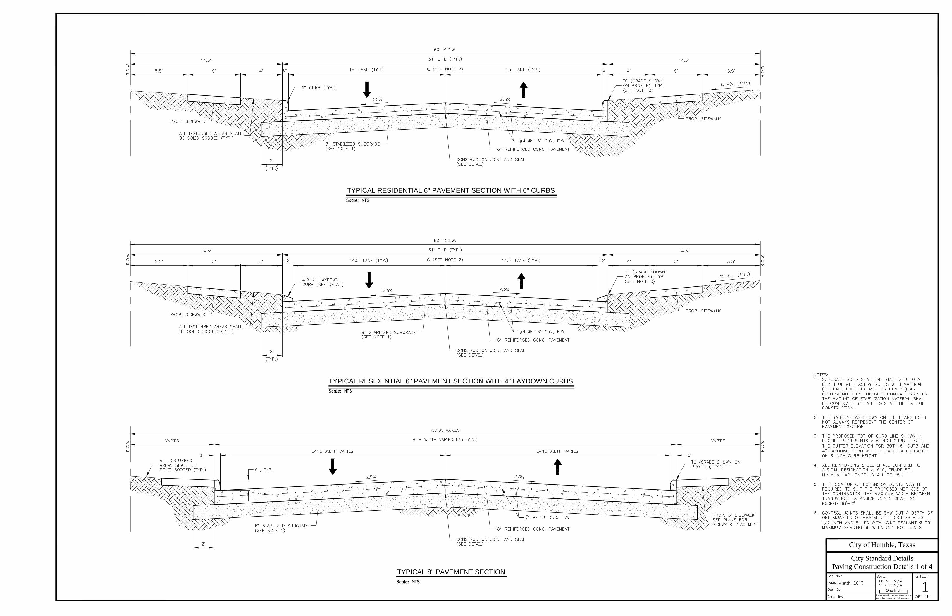
One Inch
inch, then this dwg. not to scale
City of Humble, Texas
City Standard Details
16
Paving Construction Details 1 of 4
116
TYPICAL RESIDENTIAL 6" PAVEMENT SECTION WITH 6" CURBS
TYPICAL RESIDENTIAL 6" PAVEMENT SECTION WITH 4" LAYDOWN CURBS
TYPICAL 8" PAVEMENT SECTION

One Inch
inch, then this dwg. not to scale
City of Humble, Texas
City Standard Details
16
Paving Construction Details 2 of 4
216
EXISTING
PROPOSED
¼
½
¼
UNDERCUT BAR
CONCRETE PAVING HEADER
AT EXISTING CONCRETE PAVING
SECTION A-A
6" CONCRETE CURB
NEW CONSTRUCTION
BAR HOOP DETAIL
CONCRETE PAVING HEADER
AT ASPHALT PAVING
PAVEMENT JOINT LOCATION DETAIL
WHERE PROPOSED PAVEMENT MEETS EXISTING
MONOLITHIC CURB AND GUTTER
CONSTRUCTION JOINT AND SEAL DETAIL
JOINT PLATE DETAIL
EXPANSION JOINT DETAILS
TYPICAL INTERSECTION JOINT LOCATION
4"x12" LAYDOWN CURB TYPICAL CURB TRANSITION

One Inch
inch, then this dwg. not to scale
City of Humble, Texas
City Standard Details
16
CHECKERPLATE DETAIL
SECTION A-A
DETAIL "A"
PLAN
TOP VIEW
SIDE VIEW
SIGN RELOCATION DETAIL
FILL BEHIND BACK OF CURB DETAIL
TYPICAL GRASS SODDING DETAILS
YARD DRAIN CONNECTION DETAIL
TEMPORARY POLE BRACING
FULL DEPTH ASPHALT TRANSITION DETAIL
Paving Construction Details 3 of 4
316

One Inch
inch, then this dwg. not to scale
City of Humble, Texas
City Standard Details
16
Paving Construction Details 4 of 4
416
SECTION
CONTRACTION JOINT
PLAN
SECTION A-A
DETAIL A
EXPANSION JOINT
EXISTING CONCRETE PAVEMENT CONSTRUCTION
EXISTING CURB & GUTTER CONSTRUCTION
SECTION
X
SECTION
X
A
SECTION
CURB RAMP
X
SECTION
NOT TO SCALE
TYPICAL
DETECTABLE WARNING PAVER
DETECTABLE WARNING PAVER
TRUNCATED DOME PATTERN CURB RAMP
SECTION A-A
PARALLEL CURB RAMPS
PROPOSED SIDEWALK AT
EXISTING CONCRETE DETAIL
WHEELCHAIR RAMP DETAIL
SIDEWALK AROUND OBSTRUCTION
SIDEWALK JOINT DETAILS
CONCRETE SIDEWALK DETAILS

One Inch
inch, then this dwg. not to scale
City of Humble, Texas
City Standard Details
16
SECTION B-B
DRIVEWAY DETAIL WITH 6" CURB WITH SIDEWALK
SECTION A-A
DRIVEWAY DETAIL WITH 6" CURB WITHOUT SIDEWALK
Driveway Details 1 of 2
516

One Inch
inch, then this dwg. not to scale
City of Humble, Texas
City Standard Details
16
R.O.W.
SECTION A-A
ASPHALT PAVING FOR DRIVEWAYS
CONCRETE PAVING HEADER ATDriveway Details 2 of 2
616
SECTION A-A
DRIVEWAY DETAIL AT ASPHALT PAVEMENT
PLAN
DRIVEWAY DETAIL WITH LAYDOWN CURB
PLAN

PLAN
INLET
ELEVATION
SECTION B-B
EXTENSION
One Inch
inch, then this dwg. not to scale
City of Humble, Texas
City Standard Details
16
TYPE "C" INLET DETAILS
EXTENSION INLET
BOTTOM VIEW
SECTION
REVERSE FRAME
COVER SECTION
BOTTOM VIEW
FRAME SECTION
STORM MANHOLE FRAME & COVER
PLAN ~ TEMPORARY TIMBER COVER
INLET FRAME & COVER DETAIL
A A
PLAN SECTION A-A
PRECAST STORM SEWER BOX MANHOLE
Drainage Construction Details 1 of 3
716

One Inch
inch, then this dwg. not to scale
City of Humble, Texas
City Standard Details
16
Drainage Construction Details 2 of 3
816
ELEVATION
SECTION
TYP. CONC. COLLAR DETAIL
/
//
/
SECTION THRU "I" BEAM
TYPE "B-B" INLET DETAILS
PLAN
SECTION 1-1
HALF FRONT ELEVATION
TRANS SECTION
PRECAST CURB BEAM
HALF PLAN - HALF HORIZ. SECTION
HALF FRONT ELEV. - HALF HORIZ. SECTION 2-2
"B-B" INLET PLATE DETAILS
COVER SECTION
COVER SECTION
GUTTER DEPRESSIONS FOR TYPE B-B INLET
PLAN
PLAN
SECTION A-A
PLAN
SECTION A-A
SECTION B-B
"BB" INLET GRATE DETAILS
ALTERNATE TYPE B-B INLET WITH GRATE TOP
AA
A
SECTION
PLAN
TYPE "A" GRATE INLET DETAIL

One Inch
inch, then this dwg. not to scale
City of Humble, Texas
City Standard Details
16
WET CONDITION BEDDING
Drainage Construction Details 3 of 3
916
A
A
PLAN VIEW
SECTION A-A
CONFLICT STORM SEWER MANHOLE
SPLIT CASING
PLAN SECTION
BEDDING AND BACKFILL DETAIL
FOR STORM SEWER PIPES
SECTION B-B
SECTION A-A
PLAN
TYPE "E" INLET
FOR PRECAST CONCRETE BOX
WHERE SATISFACTORY SOIL CONDITIONS EXIST
STORM SEWER BEDDING AND BACKFILL
FOR PRECAST CONCRETE BOX
WHERE UNSATISFACTORY SOIL CONDITIONS EXIST
STORM SEWER BEDDING AND BACKFILL

One Inch
inch, then this dwg. not to scale
City of Humble, Texas
City Standard Details
16
Water Line Construction Details 1 of 3
1016
SIDE ELEVATIONFRONT ELEVATION
FITTING ASSEMBLY & THRUST BLOCK DETAIL
RESTRAINED MECHANICAL JOINT VERTICAL OFFSET
GATE VALVE INSTALLATION DETAIL
STANDARD FIRE HYDRANT DETAIL
MECHANICAL RESTRAINT W/ RESTRAINING RODS
MECHANICAL JOINT RESTRAINT

One Inch
inch, then this dwg. not to scale
City of Humble, Texas
City Standard Details
16
Water Line Construction Details 2 of 3
1116
AUTOMATIC FLUSHING DEVICE
PIPE CASING SPACER SECTION
PIPE CASING SPACER DETAIL
SERVICE TAPS
SERVICE RECONNECTION
CASING DETAILS
TYPICAL RESIDENTIAL

One Inch
inch, then this dwg. not to scale
City of Humble, Texas
City Standard Details
16
Water Line Construction Details 3 of 3
1216
SECTION
A
ELEVATION
AT FOUNDATION TRENCH DAM
LONGITUDINAL SECTION ALONG PIPE CENTERLINE
FOR PIPES UNDER CONCRETE PAVEMENT
WATER PIPE TRENCH DETAIL
AUGER PIT AND AUGER HOLE
WET CONDITION BEDDING
TYPICAL CROSS-SECTION
FOR PIPES UNDER NATURAL GROUND
WATER PIPE TRENCH DETAIL
BEDDING, BACKFILL, AND SODDING NOTES FOR TRENCH DETAILS

One Inch
inch, then this dwg. not to scale
City of Humble, Texas
City Standard Details
16
Sanitary Sewer Construction Details 1 of 2
1316
AA
FOUNDATION PLAN
SANITARY SEWER PRECAST CONCRETE MANHOLE
SHALLOW MANHOLE SECTION
SECTION
A
TYPICAL CROSS - SECTION
PLAN
BOTTOM VIEW
COVER SECTION
BOLTHOLE DETAIL
FRAME SECTION
COVER SECTION
FRAME WITH MUDRING
BACKFILL OF MANHOLES AND STRUCTURES
FOR SANITARY SEWER PIPES
BEDDING AND BACKFILL DETAIL
FOR PROPOSED MANHOLE
WET CONDITION BEDDING
SECTION
A
BOLTED SANITARY MANHOLE FRAME & COVER
AA
SANITARY MANHOLE FRAME & COVER

One Inch
inch, then this dwg. not to scale
City of Humble, Texas
City Standard Details
16
Sanitary Sewer Construction Details 2 of 2
1416
TABLE "A"
CLEAN OUT DETAIL
SERVICE RECONNECTION DETAIL
SERVICE RECONNECTION DETAIL
MEASUREMENT AND PAYMENT FOR
SANITARY SEWER MANHOLE
ABANDONMENT OF EXISTING
TYPICAL SANITARY SERVICE BEDDING DETAIL
SEWET AT CONNECTION
CROSS-SECTION OF
ON EXISTING LINE WITH POURED BASE
SANITARY SEWER PRECAST MANHOLE

One Inch
inch, then this dwg. not to scale
City of Humble, Texas
City Standard Details
16
Storm Water Pollution Prevention Details 1 of 2
1516

B
IN-CHANNEL FILTER DAM
A
A
B
ROCK FILTER DAM DETAIL
FILTER DAM NOTES:
SECTION
A
SECTION
B
PLAN
RFD
One Inch
inch, then this dwg. not to scale
City of Humble, Texas
City Standard Details
16
Storm Water Pollution Prevention Details 2 of 2
1616