Embed Size (px)
Citation preview
Bicycle FacilityDesign Guide
REVISED:District Department of Transportation
Bicycle Facility Design Guide Dec. 2006 A
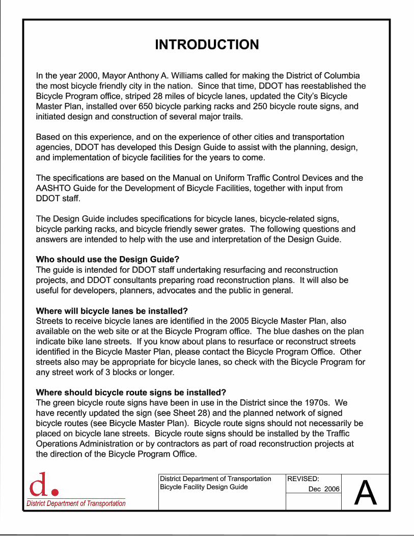
Who should use the Design Guide?
INTRODUCTION
Where will bicycle lanes be installed?
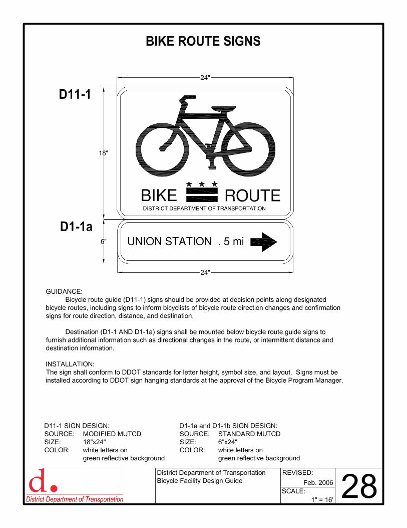
Where should bicycle route signs be installed?
In the year 2000, Mayor Anthony A. Williams called for making the District of Columbia
the most bicycle friendly city in the nation. Since that time, DDOT has reestablished the
Bicycle Program office, striped 28 miles of bicycle lanes, updated the City�s Bicycle
Master Plan, installed over 650 bicycle parking racks and 250 bicycle route signs, and
initiated design and construction of several major trails.
Based on this experience, and on the experience of other cities and transportation
agencies, DDOT has developed this Design Guide to assist with the planning, design,
and implementation of bicycle facilities for the years to come.
The specifications are based on the Manual on Uniform Traffic Control Devices and the
AASHTO Guide for the Development of Bicycle Facilities, together with input from
DDOT staff.
The Design Guide includes specifications for bicycle lanes, bicycle-related signs,
bicycle parking racks, and bicycle friendly sewer grates. The following questions and
answers are intended to help with the use and interpretation of the Design Guide.
The guide is intended for DDOT staff undertaking resurfacing and reconstruction
projects, and DDOT consultants preparing road reconstruction plans. It will also be
useful for developers, planners, advocates and the public in general.
Streets to receive bicycle lanes are identified in the 2005 Bicycle Master Plan, also
available on the web site or at the Bicycle Program office. The blue dashes on the plan
indicate bike lane streets. If you know about plans to resurface or reconstruct streets
identified in the Bicycle Master Plan, please contact the Bicycle Program Office. Other
streets also may be appropriate for bicycle lanes, so check with the Bicycle Program for
any street work of 3 blocks or longer.
The green bicycle route signs have been in use in the District since the 1970s. We
have recently updated the sign (see Sheet 28) and the planned network of signed
bicycle routes (see Bicycle Master Plan). Bicycle route signs should not necessarily be
placed on bicycle lane streets. Bicycle route signs should be installed by the Traffic
Operations Administration or by contractors as part of road reconstruction projects at
the direction of the Bicycle Program Office.
REVISED:District Department of Transportation
Bicycle Facility Design Guide Dec. 2006 B
INTRODUCTION
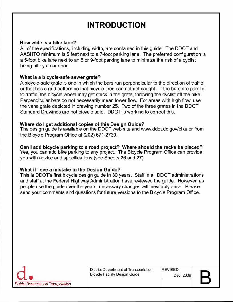
How wide is a bike lane?
What is a bicycle-safe sewer grate?
Where do I get additional copies of this Design Guide?
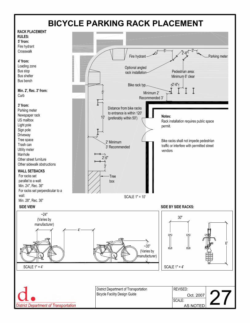
Can I add bicycle parking to a road project? Where should the racks be placed?
What if I see a mistake in the Design Guide?
All of the specifications, including width, are contained in this guide. The DDOT and
AASHTO minimum is 5 feet next to a 7-foot parking lane. The preferred configuration is
a 5-foot bike lane next to an 8 or 9-foot parking lane to minimize the risk of a cyclist
being hit by a car door.
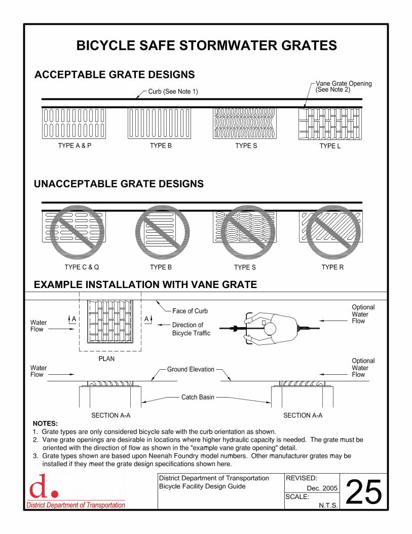
A bicycle-safe grate is one in which the bars run perpendicular to the direction of traffic
or that has a grid pattern so that bicycle tires can not get caught. If the bars are parallel
to traffic, the bicycle wheel may get stuck in the grate, throwing the cyclist off the bike.
Perpendicular bars do not necessarily mean lower flow. For areas with high flow, use
the vane grate depicted in drawing number 25. Two of the three grates in the DDOT
Standard Drawings are not bicycle safe. DDOT is working to correct this.
The design guide is available on the DDOT web site and www.ddot.dc.gov/bike or from
the Bicycle Program Office at (202) 671-2730.
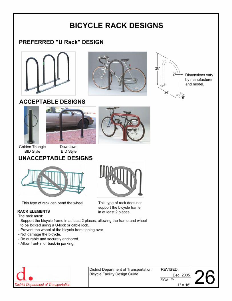
Yes, you can add bike parking to any project. The Bicycle Program Office can provide
you with advice and specifications (see Sheets 26 and 27).
This is DDOT�s first bicycle design guide in 30 years. Staff in all DDOT administrations
and staff at the Federal Highway Administration have reviewed the guide. However, as
people use the guide over the years, necessary changes will inevitably arise. Please
send your comments and questions for future versions to the Bicycle Program Office.

7’ Minimum
9’ Preferred
5’10’-12’
Travel lane
COPYRIGHT 1999 FIREHOUSE DESIGNS
6’
6’
8’
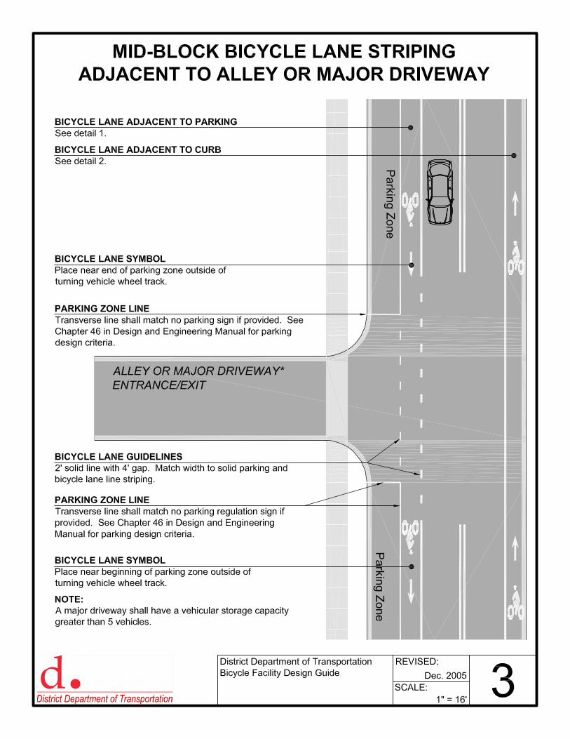
MID-BLOCK BICYCLE LANE STRIPING
ADJACENT TO PARKING
NOTES:
1. STRIPING: Utilize white thermoplastic on asphalt, high contrast tape on concrete.
2. SYMBOLS ON PAVEMENT: Utilize white preformed thermoplastic symbols.
3. SYMBOLS ON CONCRETE: Utilize high contrast tape symbols.
4. PAVEMENT CONDITION: The pavement should be inspected and damaged pavement
should be replaced prior to striping of bicycle lanes.
5. BICYCLE LANE SIGNAGE: The placement of regulation or warning signs is governed by
the MUTCD except where defined within this design guide.
1" = 5’
Dec. 2006 1SCALE:
REVISED:District Department of Transportation
Bicycle Facility Design Guide
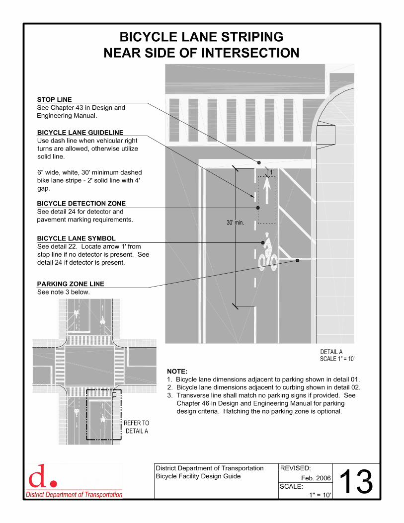
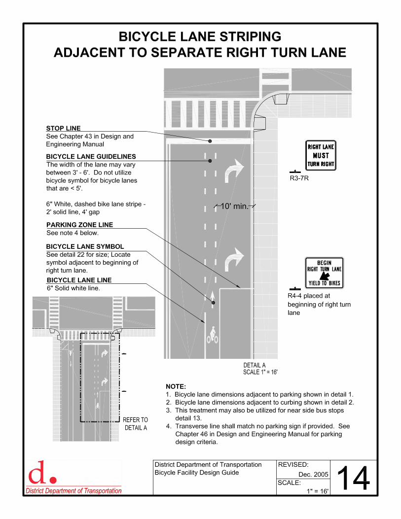
BICYCLE LANE LINE
6" Solid white line.
PARKING LANE LINE
4" Solid white line.
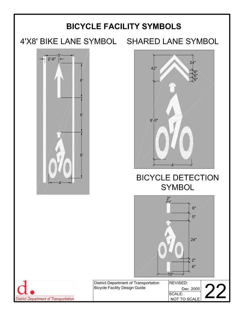
BICYCLE LANE SYMBOL
Utilize 4’x8’ preformed symbol. See
detail 22.
PARKING LANE
See Chapter 46 in Design and
Engineering Manual.
BICYCLE LANE
Bicycle lane is 5’ minimum width.
TRAVEL LANE
Typical lane widths will vary between
10’-12’. The number of travel lanes will
vary.
CURB AND GUTTER
Gutter is typically 1’ to 2’ in width of
concrete or brick material. All lane width
measurements are to face of curb.
10’-12’
Travel lane
5’
6’
6’
8’
3’ Min.
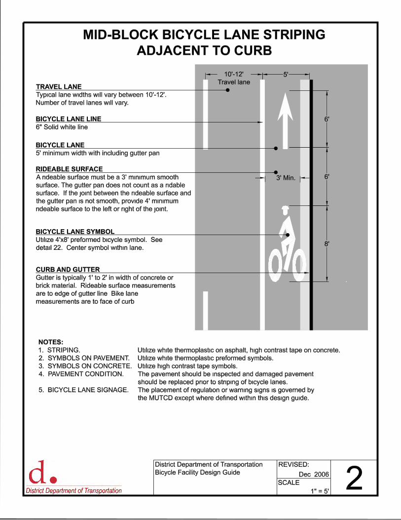
MID-BLOCK BICYCLE LANE STRIPING
ADJACENT TO CURB
BICYCLE LANE LINE
6" Solid white line.
BICYCLE LANE SYMBOL
Utilize 4’x8’ preformed bicycle symbol. See
detail 22. Center symbol within lane.
BICYCLE LANE
5’ minimum width with including gutter pan.
TRAVEL LANE
Typical lane widths will vary between 10’-12’.
Number of travel lanes will vary.
CURB AND GUTTER
Gutter is typically 1’ to 2’ in width of concrete or
brick material. Rideable surface measurements
are to edge of gutter line. Bike lane
measurements are to face of curb.
1" = 5’
Dec. 2006 2SCALE:
REVISED:District Department of Transportation
Bicycle Facility Design Guide
NOTES:
1. STRIPING: Utilize white thermoplastic on asphalt, high contrast tape on concrete.
2. SYMBOLS ON PAVEMENT: Utilize white thermoplastic preformed symbols.
3. SYMBOLS ON CONCRETE: Utilize high contrast tape symbols.
4. PAVEMENT CONDITION: The pavement should be inspected and damaged pavement
should be replaced prior to striping of bicycle lanes.
5. BICYCLE LANE SIGNAGE: The placement of regulation or warning signs is governed by
the MUTCD except where defined within this design guide.
RIDEABLE SURFACE
A rideable surface must be a 3’ minimum smooth
surface. The gutter pan does not count as a ridable
surface. If the joint between the rideable surface and
the gutter pan is not smooth, provide 4’ minimum
rideable surface to the left or right of the joint.
8’ 7’
COPYRIGHT 1999 FIREHOUSE DESIGNS
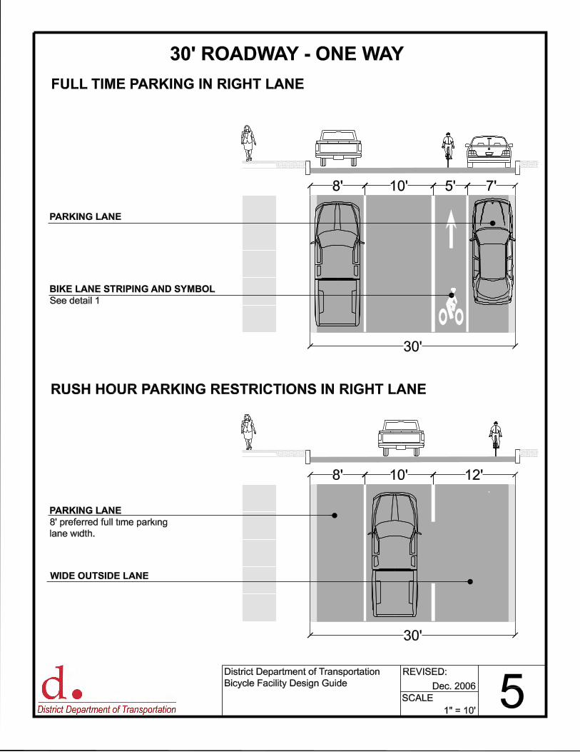
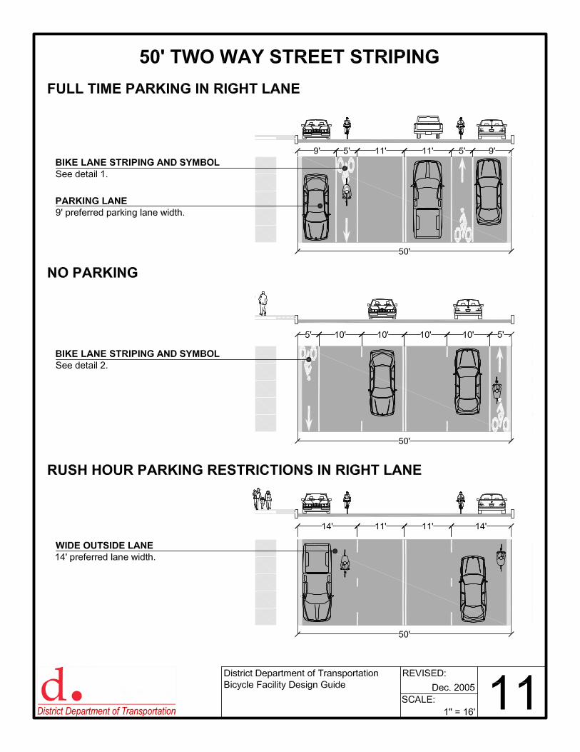
FULL TIME PARKING IN RIGHT LANE
BIKE LANE STRIPING AND SYMBOL
See detail 1
PARKING LANE
RUSH HOUR PARKING RESTRICTIONS IN RIGHT LANE
10’
WIDE OUTSIDE LANE
PARKING LANE
8’ preferred full time parking
lane width.
8’ 12’10’
5’
30’
30’
30’ ROADWAY - ONE WAY
1" = 10’
Dec. 2006 5SCALE:
REVISED:District Department of Transportation
Bicycle Facility Design Guide
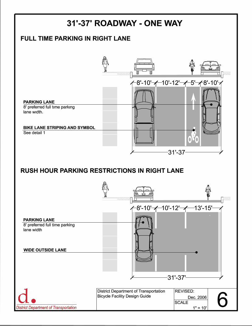
8’-10’ 8’-10’
COPYRIGHT 1999 FIREHOUSE DESIGNS
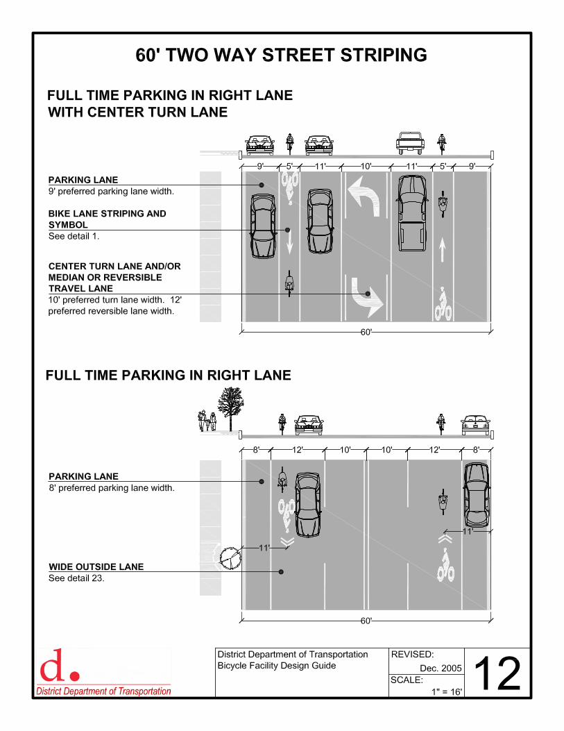
FULL TIME PARKING IN RIGHT LANE
BIKE LANE STRIPING AND SYMBOL
See detail 1.
PARKING LANE
8’ preferred full time parking
lane width. COPYRIGHT 1999 FIREHOUSE DESIGNS
RUSH HOUR PARKING RESTRICTIONS IN RIGHT LANE
10’-12’
WIDE OUTSIDE LANE
PARKING LANE
8’ preferred full time parking
lane width.
8’-10’ 13’-15’10’-12’
5’
31’-37
31’-37’
31’-37’ ROADWAY - ONE WAY
1" = 10’6SCALE:
REVISED:District Department of Transportation
Bicycle Facility Design Guide Dec. 2006
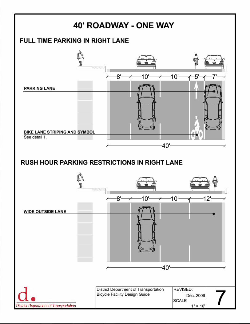
8’ 10’ 7’
COPYRIGHT 1999 FIREHOUSE DESIGNS
40’
PARKING LANE
BIKE LANE STRIPING AND SYMBOL
See detail 1.
10’ 5’
COPYRIGHT 1999 FIREHOUSE DESIGNS
8’ 10’
COPYRIGHT 1999 FIREHOUSE DESIGNS
40’
10’ 12’
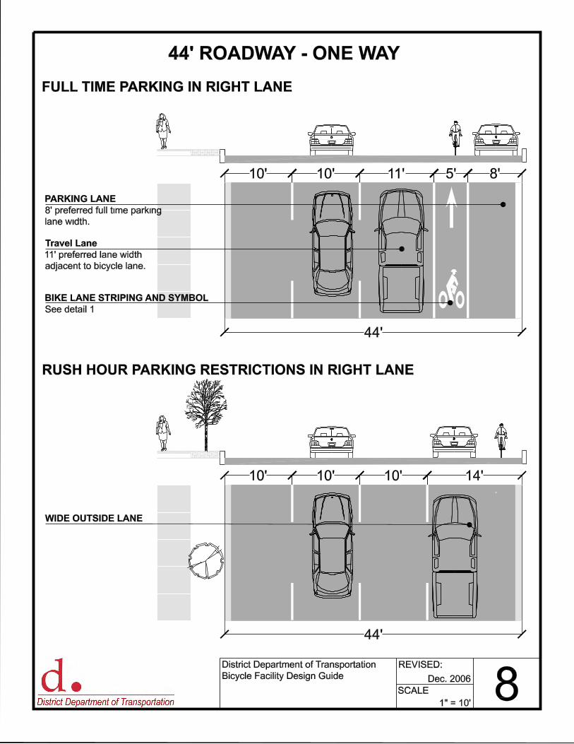
FULL TIME PARKING IN RIGHT LANE
RUSH HOUR PARKING RESTRICTIONS IN RIGHT LANE
WIDE OUTSIDE LANE
District Department of Transportation
Bicycle Facility Design Guide
REVISED:
SCALE: 7Dec. 2006
1" = 10’
40’ ROADWAY - ONE WAY
COPYRIGHT 1999 FIREHOUSE DESIGNS
10’ 10’ 14’
COPYRIGHT 1999 FIREHOUSE DESIGNS
10’
10’ 11’ 8’10’ 5’
FULL TIME PARKING IN RIGHT LANE
PARKING LANE
8’ preferred full time parking
lane width.
BIKE LANE STRIPING AND SYMBOL
See detail 1.
RUSH HOUR PARKING RESTRICTIONS IN RIGHT LANE
Travel Lane
11’ preferred lane width
adjacent to bicycle lane.
WIDE OUTSIDE LANE
44’
44’
44’ ROADWAY - ONE WAY
1" = 10’
Dec. 2006 8SCALE:
REVISED:District Department of Transportation
Bicycle Facility Design Guide
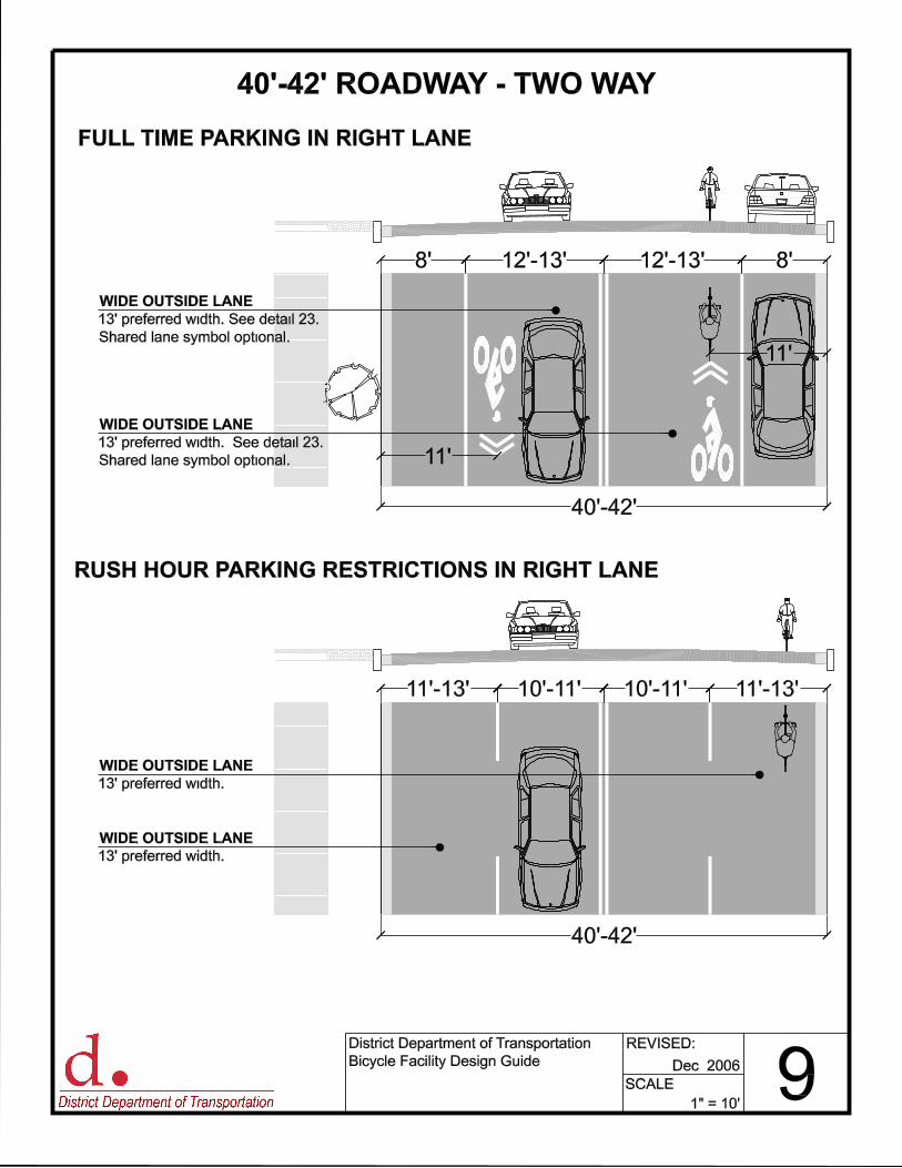
COPYRIGHT 1999 FIREHOUSE DESIGNS
8’ 12’-13’ 12’-13’ 8’
40’-42’
COPYRIGHT 1999 FIREHOUSE DESIGNS
11’-13’ 10’-11’ 10’-11’ 11’-13’
40’-42’
WIDE OUTSIDE LANE
13’ preferred width. See detail 23.
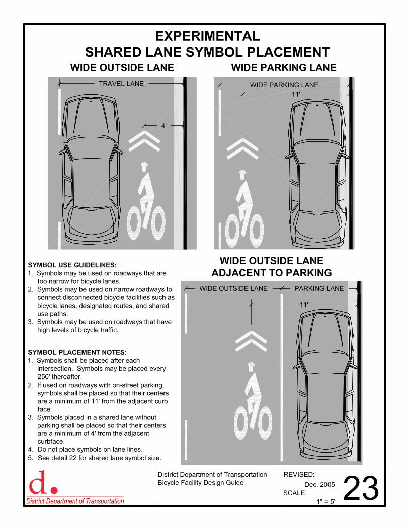
Shared lane symbol optional.
FULL TIME PARKING IN RIGHT LANE
RUSH HOUR PARKING RESTRICTIONS IN RIGHT LANE
COPYRIGHT 1999 FIREHOUSE DESIGNS
11’
WIDE OUTSIDE LANE
13’ preferred width. See detail 23.
Shared lane symbol optional. 11’
WIDE OUTSIDE LANE
13’ preferred width.
WIDE OUTSIDE LANE
13’ preferred width.
District Department of Transportation
Bicycle Facility Design Guide
REVISED:
SCALE: 91" = 10’
40’-42’ ROADWAY - TWO WAY
Dec. 2006
COPYRIGHT 1999 FIREHOUSE DESIGNSCOPYRIGHT 1999 FIREHOUSE DESIGNSCOPYRIGHT 1999 FIREHOUSE DESIGNS
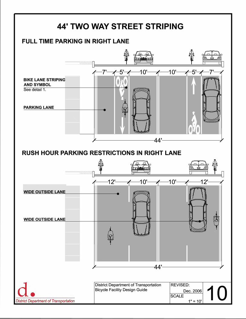
BIKE LANE STRIPING
AND SYMBOL
See detail 1.
PARKING LANE
12’ 10’ 10’ 12’
COPYRIGHT 1999 FIREHOUSE DESIGNS
44’
44’
RUSH HOUR PARKING RESTRICTIONS IN RIGHT LANE
FULL TIME PARKING IN RIGHT LANE
WIDE OUTSIDE LANE
WIDE OUTSIDE LANE
7’ 5’ 10’ 10’ 5’ 7’
44’ TWO WAY STREET STRIPING
District Department of Transportation
Bicycle Facility Design Guide
REVISED:
SCALE: 10Dec. 2006
1" = 10’
24"
LOOKFORBIKES
18"
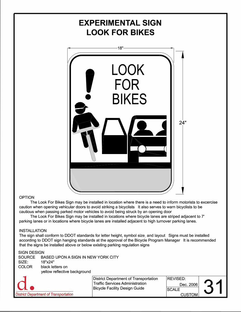
EXPERIMENTAL SIGN
LOOK FOR BIKES
District Department of Transportation
Traffic Services Administration
Bicycle Facility Design Guide
REVISED:
SCALE: 31Dec. 2006
CUSTOM
SIGN DESIGN:
SOURCE: BASED UPON A SIGN IN NEW YORK CITY
SIZE: 18"x24"
COLOR: black letters on
yellow reflective background
OPTION:
The Look For Bikes Sign may be installed in location where there is a need to inform motorists to excercise
caution when opening vehicular doors to avoid striking a bicyclists. It also serves to warn bicyclists to be
cautious when passing parked motor vehicles to avoid being struck by an opening door.
The Look For Bikes Sign may be installed in locations where bicycle lanes are striped adjacent to 7’
parking lanes or in locations where bicycle lanes are installed adjacent to high turnover parking lanes.
INSTALLATION:
The sign shall conform to DDOT standards for letter height, symbol size, and layout. Signs must be installed
according to DDOT sign hanging standards at the approval of the Bicycle Program Manager. It is recommended
that the signs be installed above or below existing parking regulation signs.
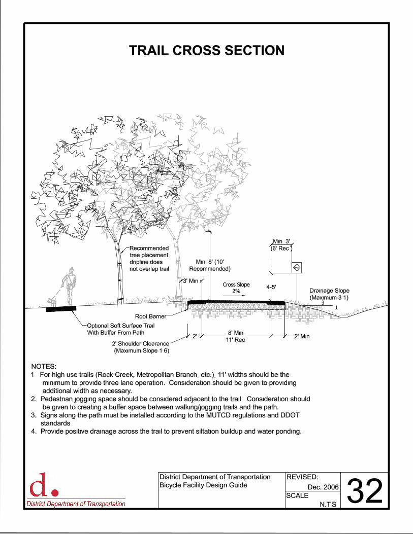
Min. 8’ (10’
Recommended)
Min. 3’
(6’ Rec.)
Cross Slope
2%4-5’
2’ Shoulder Clearance
(Maximum Slope 1:6)
LOGO
31
Drainage Slope
(Maximum 3:1)
Recommended
tree placement:
dripline does
not overlap trail.
3’ Min.
8’ Min.
11’ Rec.
Root Barrier
2’ Min.2’
NOTES:
1. For high use trails (Rock Creek, Metropolitan Branch, etc.), 11’ widths should be the
minimum to provide three lane operation. Consideration should be given to providing
additional width as necessary.
2. Pedestrian jogging space should be considered adjacent to the trail. Consideration should
be given to creating a buffer space between walking/jogging trails and the path.
3. Signs along the path must be installed according to the MUTCD regulations and DDOT
standards.
4. Provide positive drainage across the trail to prevent siltation buildup and water ponding.
Optional Soft Surface Trail
With Buffer From Path
TRAIL CROSS SECTION
District Department of Transportation
Bicycle Facility Design Guide
REVISED:
SCALE: 32N.T.S.
Dec. 2006
8’
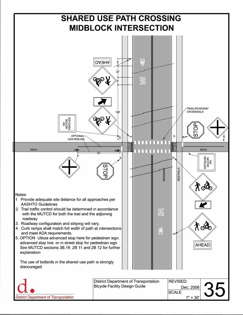
32’
8’
100’
50’
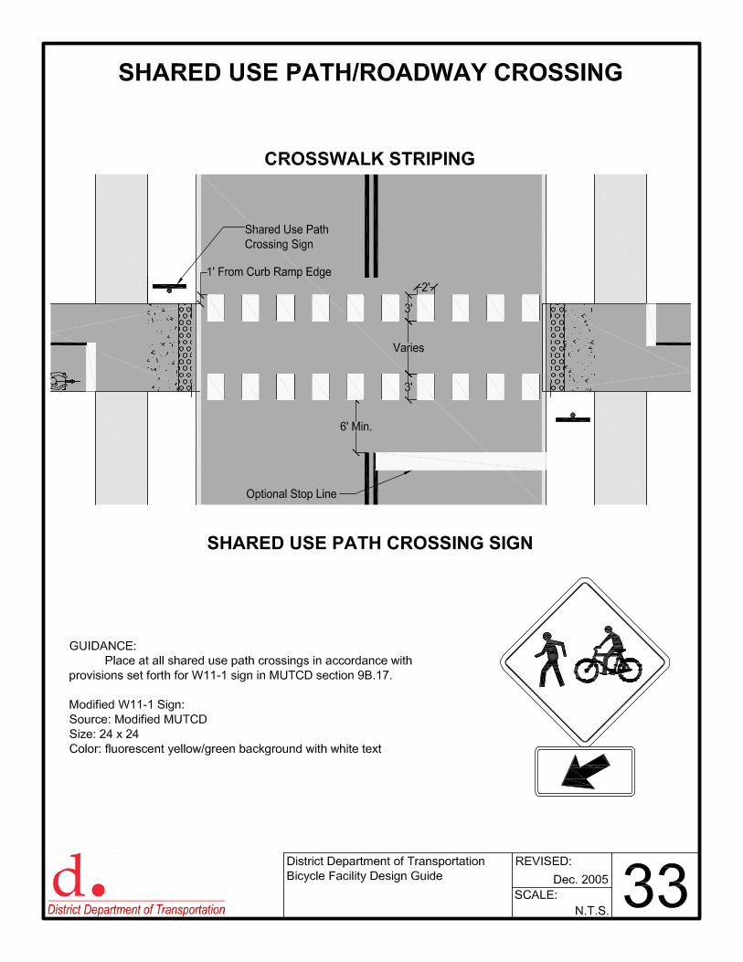
TRAIL/ROADWAY
CROSSWALK
PATH
SID
EW
AL
K
RO
AD
WA
Y
OPTIONAL
CENTERLINE
PATH
ST
OP
NO
MO
TO
R
VE
HIC
LE
S
AHEAD
AHEAD
NO
MO
TO
R
VE
HIC
LE
S
ST
OP
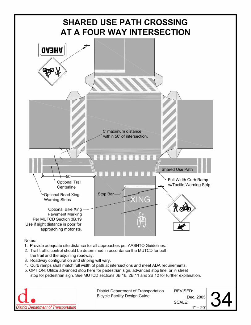
Notes:
1. Provide adequate site distance for all approaches per
AASHTO Guidelines.
2. Trail traffic control should be determined in accordance
with the MUTCD for both the trail and the adjoining
roadway.
3. Roadway configuration and striping will vary.
4. Curb ramps shall match full width of path at intersections
and meet ADA requirements.
5. OPTION: Utilize advanced stop here for pedestrian sign,
advanced stop line, or in street stop for pedestrian sign.
See MUTCD sections 3B.16 ,2B.11 and 2B.12 for further
explanation.
The use of bollards in the shared use path is strongly
discouraged.
SHARED USE PATH CROSSING
MIDBLOCK INTERSECTION
District Department of Transportation
Bicycle Facility Design Guide
REVISED:
SCALE: 35Dec. 2006
1" = 30’
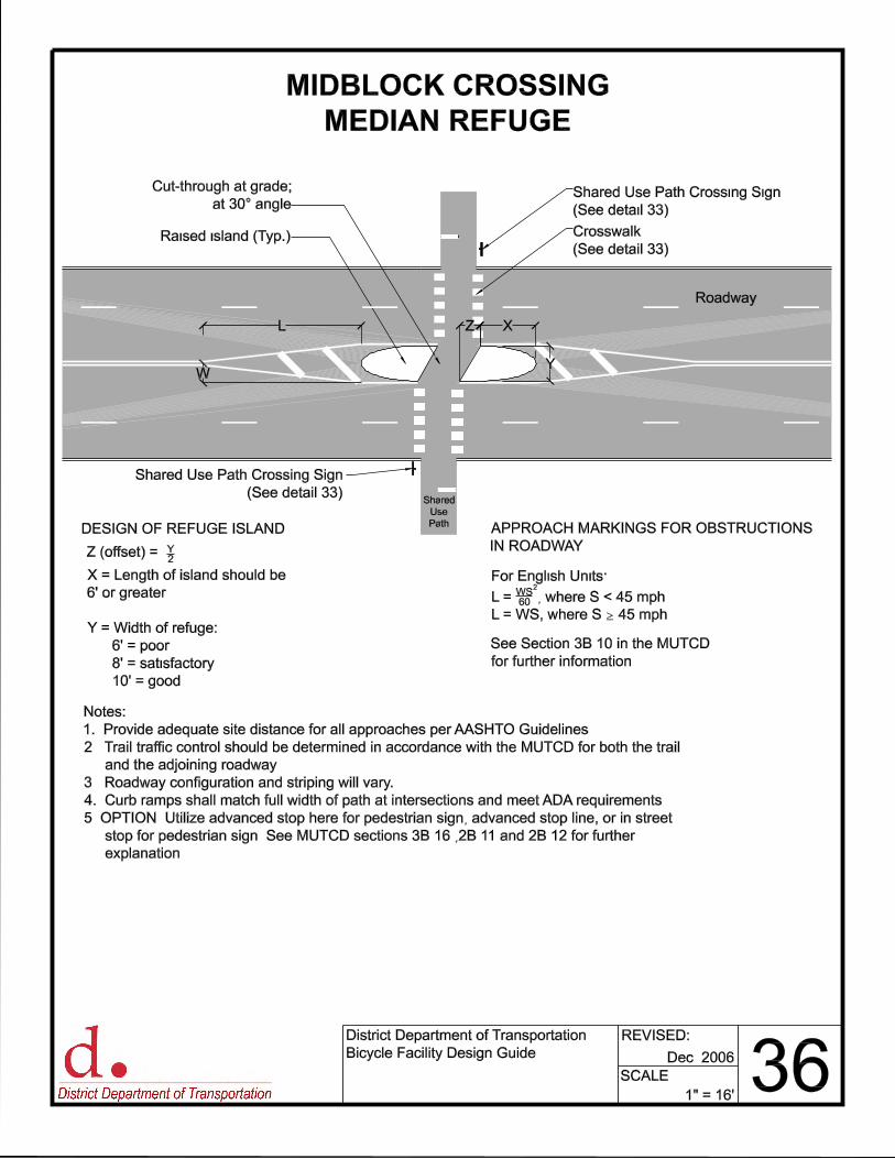
MIDBLOCK CROSSING
MEDIAN REFUGE
District Department of Transportation
Bicycle Facility Design Guide
REVISED:
SCALE: 36Dec. 2006
1" = 16’
Notes:
1. Provide adequate site distance for all approaches per AASHTO Guidelines.
2. Trail traffic control should be determined in accordance with the MUTCD for both the trail
and the adjoining roadway.
3. Roadway configuration and striping will vary.
4. Curb ramps shall match full width of path at intersections and meet ADA requirements.
5. OPTION: Utilize advanced stop here for pedestrian sign, advanced stop line, or in street
stop for pedestrian sign. See MUTCD sections 3B.16 ,2B.11 and 2B.12 for further
explanation.
Raised island (Typ.)
Cut-through at grade;
at 30° angle
Shared
Use
Path
X = Length of island should be
6’ or greater
Y = Width of refuge:
6’ = poor
8’ = satisfactory
10’ = good
Roadway
Crosswalk
(See detail 33)
Y
Z (offset) = Y2
For English Units:
L = WS60 , where S < 45 mph
L = WS, where S = 45 mph
DESIGN OF REFUGE ISLAND APPROACH MARKINGS FOR OBSTRUCTIONS
IN ROADWAY
2
Shared Use Path Crossing Sign
(See detail 33)
Shared Use Path Crossing Sign
(See detail 33)
See Section 3B.10 in the MUTCD
for further information.
L XZ
W