Embed Size (px)
Citation preview
Design, Modeling and Control of a Series Elastic Actuator for anAssistive Knee Exoskeleton
Nikos C. Karavas, Nikos G. Tsagarakis and Darwin G. CaldwellIstituto Italiano di Tecnologia (IIT)
Abstract— This paper introduces the design, modeling andcontrol of a novel inherently compliant actuator with theability to manually reconfigure the level of stiffness (CompAct-ARS). CompAct-ARS is intended to be utilized in assistivedevices for legs, which will aid users in different motion taskssuch as walking, sit-to-stand movement and squatting and willdemonstrate the benefits of passive compliance. The actuatormodeling design and mechanics are introduced. Experimentaland simulation data are used in order to determine the designspecifications of the actuator for its use in a knee exoskeletonsystem. Finally an assistive control strategy is introduced thatwill allow the proposed system to provide motion assistance tothe subject knee.
I. INTRODUCTION
Lower limb exoskeletons can be used for human perfor-
mance augmentation, assistive locomotion and rehabilitation
purposes. Human performance augmenting exoskeletons can
enhance the user’s capability to carry heavy loads and/or
increase the muscle activation during different motion tasks
[1], [2], [3]. Assistive exoskeletons are aimed at assistive am-
bulation for individuals with impaired legs [4], [5], although
they can also be used to assist sound function. On the other
hand the goal of rehabilitation exoskeletons [6], [7] is to
provide a gait rehabilitation solution to patients preferably
when residing outside the clinic and without the support of
a physiotherapist.
These robotic devices have mutual requirements regarding
their actuation performance, the weight and size of both
actuator and structure, the wearability of their design and
the safety of the user. Researchers who are focused on the
development of exoskeletons have made efforts to address
these aspects. However, there still remain limitations to be
overcome before this technology can be used effectively [8].
As exoskeletons are devices wearable by humans, safety of
interaction is crucial requirement in preventing both injury
and discomfort [9]. The enabling technology and the control
strategy are the keys to achieve safety and adaptability
of physical human-robot interaction (pHRI). To date the
majority of the presented exoskeletons employ stiff actuators,
which impose on the exoskeletons significant limitations
related to safety issues and the ability to interact with
human. This substantially relies on the fact that the high
frequency output impedance of a stiff actuator is dominated
The authors are within the Department of AdvancedRobotics, Istituto Italiano di Tecnologia, via Morego, 30, 16163Genova {nikolaos.karavas, nikos.tsagarakis,darwin.caldwell}@iit.it
by the reflected inertia of the rotor. For this purpose, safe-
oriented control techniques have been proposed to improve
the dynamic behavior of stiff actuation during pHRI [10],
however there are ineffective for frequencies above the closed
loop bandwidth of the control system.
Introducing inherent compliance to the actuation system
decouples the inertia of the motor drive from the output link
and renders the output mechanical impedance lower across
the frequency spectrum [11]. Thus, the robot improves its
ability to intrinsically absorb impacts and enhances physical
human-robot interaction. In addition, due to the presence
of the employed passive elements which can store and
release energy during one cycle of a periodical motion,
compliant robots can be more energy efficient as compared
to traditional stiff actuated systems. This feature is critical
in the creation of energetically autonomous exoskeletons for
locomotion.
In order to achieve the features described above, our
primary goal is to build an inherently compliant lower body
exoskeleton to be used as a lower limb assistive device. First
step along this path is the development of a compliant knee
exoskeleton, which will provide motion assistance both to pa-
tients with impaired legs and healthy individuals for different
motion tasks such as walking, standing up-sitting down and
squatting. The realization of such a compliant exoskeleton
remains a challenging task requiring more compact, modular
and high performance actuation units. This paper presents the
design, modeling and control of CompAct-ARS (Actuator
with Reconfigurable Stiffness). CompAct-ARS is an intrinsic
compliant actuator with manually reconfigurable stiffness
which has the ability to provide the required assistive torques
to the knee joints of the wearer.
II. COMPACT-ARS
A. Functional Principle of CompAct-ARS
CompAct-ARS as mentioned above is a series elastic
actuator with the ability to regulate off-line the level of
stiffness in as wide a range as needed. This feature permits
the experimentation with different compliance levels and
the adaptation of the joint to fit specific task requirements.
The elimination of active tuning of the spring stiffness
through a second motor was performed to reduce the weight
and dimensions of the unit. The working principle of the
CompAct-ARS is based on the CompAct-VSA (Variable
Stiffness Actuator) [12], which uses a lever arm mechanism
with a variable pivot axis. As it is shown in Fig. 1 the springs
are kept fixed while the position of the pivot is changing.
The Fourth IEEE RAS/EMBS International Conferenceon Biomedical Robotics and BiomechatronicsRoma, Italy. June 24-27, 2012
978-1-4577-1198-5/12/$26.00 ©2012 IEEE 1813
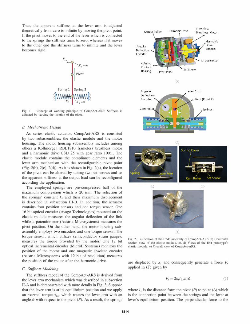
Thus, the apparent stiffness at the lever arm is adjusted
theoretically from zero to infinite by moving the pivot point.
If the pivot moves to the end of the lever which is connected
to the springs the stiffness turns to zero, whereas if it moves
to the other end the stiffness turns to infinite and the lever
becomes rigid.
Pivot
extF
SF
Spring 1 Spring 2
SK = ∞
0SK =
Fig. 1. Concept of working principle of CompAct-ARS; Stiffness isadjusted by varying the location of the pivot.
B. Mechatronic Design
As series elastic actuator, CompAct-ARS is consisted
by two subassemblies: the elastic module and the motor
housing. The motor housing subassembly includes among
others a Kollmorgen RBE1810 frameless brushless motor
and a harmonic drive CSD 25 with gear ratio 100:1. The
elastic module contains the compliance elements and the
lever arm mechanism with the reconfigurable pivot point
(Fig. 2(b), 2(c), 2(d)). As it is shown in Fig. 2(a), the location
of the pivot can be altered by tuning two set screws and so
the apparent stiffness at the output load can be reconfigured
according the application.
The employed springs are pre-compressed half of the
maximum compression which is 20 mm. The selection of
the springs’ constant ks and their maximum displacement
is described in subsection III-B. In addition, the actuator
contains four position sensors and one torque sensor. One
16 bit optical encoder (Avago Technologies) mounted on the
elastic module measures the angular deflection of the link
while a potentiometer (Austria Microsystems) measures the
pivot position. On the other hand, the motor housing sub-
assembly employs two encoders and one torque sensor. The
torque sensor, which utilizes semiconductor strain gauges,
measures the torque provided by the motor. One 12 bit
optical incremental encoder (MicroE Systems) monitors the
position of the motor and one magnetic absolute encoder
(Austria Microsystems with 12 bit of resolution) measures
the position of the motor after the harmonic drive.
C. Stiffness Modeling
The stiffness model of the CompAct-ARS is derived from
the lever arm mechanism which was described in subsection
II-A and is demonstrated with more details in Fig. 3. Suppose
that the lever arm is at its equilibrium position and we apply
an external torque τext which rotates the lever arm with an
angle φ with respect to the pivot (P). As a result, the springs
(a)
(b)
Spring Lever Arm
(c)
Spring Cover
Cam Roller Set Screw
(d)
(e)
Fig. 2. a) Section of the CAD assembly of CompAct-ARS. b) Horizontalsection view of the elastic module. c), d) Views of the first prototype’selastic module. e) Overall view of CompAct-ARS.
are displaced by xs and consequently generate a force Fsapplied in (Γ) given by
Fs = 2ksl1 tanφ (1)
where l1 is the distance form the pivot (P) to point (Δ) which
is the connection point between the springs and the lever at
lever’s equilibrium position. The perpendicular force to the
1814
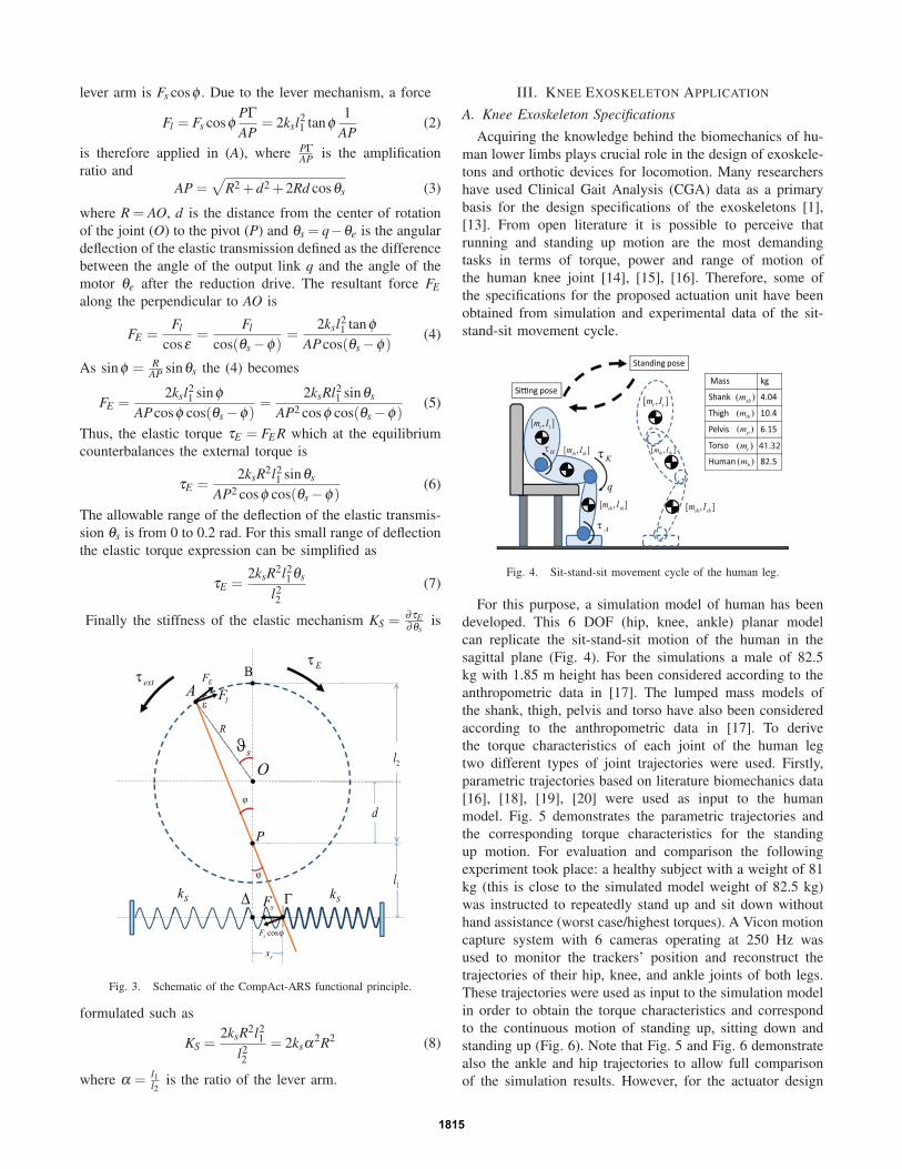
lever arm is Fs cosφ . Due to the lever mechanism, a force
Fl = Fs cosφPΓAP
= 2ksl21 tanφ
1
AP(2)
is therefore applied in (A), where PΓAP is the amplification
ratio and
AP =√
R2 +d2 +2Rd cosθs (3)
where R = AO, d is the distance from the center of rotation
of the joint (O) to the pivot (P) and θs = q−θe is the angular
deflection of the elastic transmission defined as the difference
between the angle of the output link q and the angle of the
motor θe after the reduction drive. The resultant force FEalong the perpendicular to AO is
FE =Fl
cosε=
Fl
cos(θs −φ)=
2ksl21 tanφ
APcos(θs −φ)(4)
As sinφ = RAP sinθs the (4) becomes
FE =2ksl2
1 sinφAPcosφ cos(θs −φ)
=2ksRl2
1 sinθs
AP2 cosφ cos(θs −φ)(5)
Thus, the elastic torque τE = FER which at the equilibrium
counterbalances the external torque is
τE =2ksR2l2
1 sinθs
AP2 cosφ cos(θs −φ)(6)
The allowable range of the deflection of the elastic transmis-
sion θs is from 0 to 0.2 rad. For this small range of deflection
the elastic torque expression can be simplified as
τE =2ksR2l2
1θs
l22
(7)
Finally the stiffness of the elastic mechanism KS = ∂τE∂θs
is
Β
Δ
O
A
P
ΓsF
sϑ
ϕ
ϕ
extτ
Eτ
ε
EF
lF
cossF ϕ
Sk
Sk
1l
2l
d
R
sx
Fig. 3. Schematic of the CompAct-ARS functional principle.
formulated such as
KS =2ksR2l2
1
l22
= 2ksα2R2 (8)
where α = l1l2
is the ratio of the lever arm.
III. KNEE EXOSKELETON APPLICATION
A. Knee Exoskeleton Specifications
Acquiring the knowledge behind the biomechanics of hu-
man lower limbs plays crucial role in the design of exoskele-
tons and orthotic devices for locomotion. Many researchers
have used Clinical Gait Analysis (CGA) data as a primary
basis for the design specifications of the exoskeletons [1],
[13]. From open literature it is possible to perceive that
running and standing up motion are the most demanding
tasks in terms of torque, power and range of motion of
the human knee joint [14], [15], [16]. Therefore, some of
the specifications for the proposed actuation unit have been
obtained from simulation and experimental data of the sit-
stand-sit movement cycle.
Si�ng pose
Standing pose
[ , ]t tm I
[ , ]th thm I
[ , ]t tm I
[ , ]sh shm I [ , ]
sh shm I
[ , ]th thm I
q
Mass kg
Shank 4.04
Thigh 10.4
Pelvis 6.15
Torso
Human 82.5
41.32
( )shm
( )thm
( )pm
( )tm
( )hm
Hτ
Aτ
Kτ
Fig. 4. Sit-stand-sit movement cycle of the human leg.
For this purpose, a simulation model of human has been
developed. This 6 DOF (hip, knee, ankle) planar model
can replicate the sit-stand-sit motion of the human in the
sagittal plane (Fig. 4). For the simulations a male of 82.5
kg with 1.85 m height has been considered according to the
anthropometric data in [17]. The lumped mass models of
the shank, thigh, pelvis and torso have also been considered
according to the anthropometric data in [17]. To derive
the torque characteristics of each joint of the human leg
two different types of joint trajectories were used. Firstly,
parametric trajectories based on literature biomechanics data
[16], [18], [19], [20] were used as input to the human
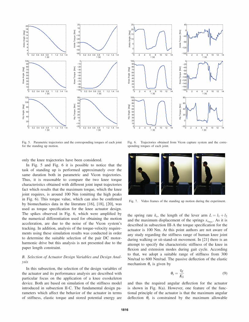
model. Fig. 5 demonstrates the parametric trajectories and
the corresponding torque characteristics for the standing
up motion. For evaluation and comparison the following
experiment took place: a healthy subject with a weight of 81
kg (this is close to the simulated model weight of 82.5 kg)
was instructed to repeatedly stand up and sit down without
hand assistance (worst case/highest torques). A Vicon motion
capture system with 6 cameras operating at 250 Hz was
used to monitor the trackers’ position and reconstruct the
trajectories of their hip, knee, and ankle joints of both legs.
These trajectories were used as input to the simulation model
in order to obtain the torque characteristics and correspond
to the continuous motion of standing up, sitting down and
standing up (Fig. 6). Note that Fig. 5 and Fig. 6 demonstrate
also the ankle and hip trajectories to allow full comparison
of the simulation results. However, for the actuator design
1815
0 0.2 0.4 0.6 0.8 1 1.2 1.4 1.62468
101214161820
Ank
le A
ngle
[de
g]
t [s]0 0.2 0.4 0.6 0.8 1 1.2 1.4 1.6
−60
−50
−40
−30
−20
−10
0
10
20
Ank
le T
orqu
e [N
m]
t [s]
0 0.2 0.4 0.6 0.8 1 1.2 1.4 1.60
102030405060708090
100
Kne
e A
ngle
[de
g]
t [s]0 0.2 0.4 0.6 0.8 1 1.2 1.4 1.6
−100−90−80−70−60−50−40−30−20−10
0
Kne
e To
rque
[N
m]
t [s]
0 0.2 0.4 0.6 0.8 1 1.2 1.4 1.60
20
40
60
80
100
120
Hip
Ang
le [
deg]
t [s]0 0.2 0.4 0.6 0.8 1 1.2 1.4 1.6
−20−10
01020304050607080
Hip
Tor
que
[Nm
]
t [s]
Fig. 5. Parametric trajectories and the corresponding torques of each jointfor the standing up motion.
only the knee trajectories have been considered.
In Fig. 5 and Fig. 6 it is possible to notice that the
task of standing up is performed approximately over the
same duration both in parametric and Vicon trajectories.
Thus, it is reasonable to compare the two knee torque
characteristics obtained with different joint input trajectories
fact which results that the maximum torque, which the knee
joint requires, is around 100 Nm (omitting the high peaks
in Fig. 6). This torque value, which can also be confirmed
by biomechanics data in the literature [16], [18], [20], was
used as torque specification for the knee actuator design.
The spikes observed in Fig. 6, which were amplified by
the numerical differentiation used for obtaining the motion
acceleration, are due to the noise of the Vicon system’s
tracking. In addition, analysis of the torque-velocity require-
ments using these simulation results was conducted in order
to determine the suitable selection of the pair DC motor-
harmonic drive but this analysis is not presented due to the
paper length constraint.
B. Selection of Actuator Design Variables and Design Anal-ysis
In this subsection, the selection of the design variables of
the actuator and its performance analysis are described with
particular focus on the application of a knee exoskeleton
device. Both are based on simulation of the stiffness model
introduced in subsection II-C. The fundamental design pa-
rameters which affect the behavior of the actuator in terms
of stiffness, elastic torque and stored potential energy are
0 2 4 6 8 10 12 14−5
0
5
10
15
20
25
Ank
le A
ngle
[de
g]
t [s]0 2 4 6 8 10 12 14
−160
−120
−80
−40
0
40
Ank
le T
orqu
e [N
m]
t [s]
0 2 4 6 8 10 12 140
102030405060708090
100
Kne
e A
ngle
[de
g]
t [s]0 2 4 6 8 10 12 14
−180−160−140−120−100−80−60−40−20
0
Kne
e To
rque
[N
m]
t [s]
0 2 4 6 8 10 12 140
102030405060708090
100
Hip
Ang
le [
deg]
t [s]0 2 4 6 8 10 12 14
−20
0
20
40
60
80
Hip
Tor
que
[Nm
]
t [s]
Fig. 6. Trajectories obtained from Vicon capture system and the corre-sponding torques of each joint.
Fig. 7. Video frames of the standing up motion during the experiment.
the spring rate ks, the length of the lever arm L = l1 + l2and the maximum displacement of the springs xsmax . As it is
described in subsection III-A the torque specification for the
actuator is 100 Nm. At this point authors are not aware of
any study regarding the stiffness range of human knee joint
during walking or sit-stand-sit movement. In [21] there is an
attempt to specify the characteristic stiffness of the knee in
flexion and extension modes during gait cycle. According
to that, we adopt a suitable range of stiffness from 300
Nm/rad to 600 Nm/rad. The passive deflection of the elastic
mechanism θs is given by
θs =τE
KS(9)
and thus the required angular deflection for the actuator
is shown in Fig. 8(a). However, one feature of the func-
tional principle of the actuator is that the maximum angular
deflection θs is constrained by the maximum allowable
1816
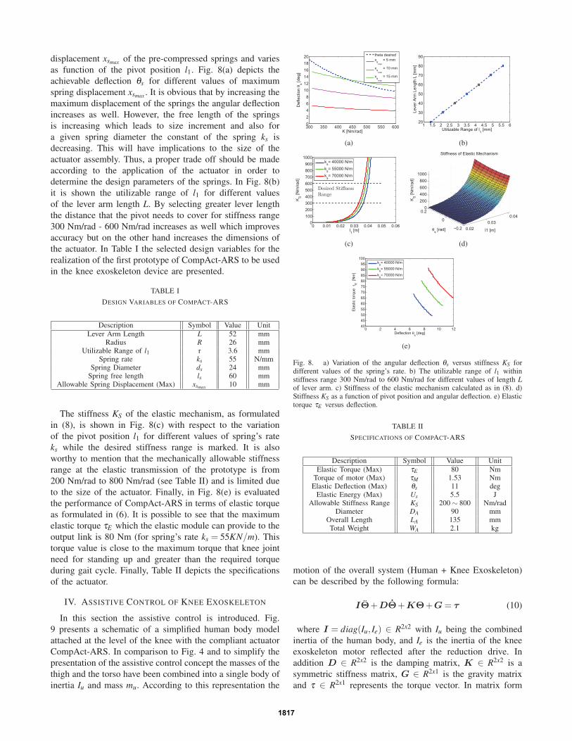
displacement xsmax of the pre-compressed springs and varies
as function of the pivot position l1. Fig. 8(a) depicts the
achievable deflection θs for different values of maximum
spring displacement xsmax . It is obvious that by increasing the
maximum displacement of the springs the angular deflection
increases as well. However, the free length of the springs
is increasing which leads to size increment and also for
a given spring diameter the constant of the spring ks is
decreasing. This will have implications to the size of the
actuator assembly. Thus, a proper trade off should be made
according to the application of the actuator in order to
determine the design parameters of the springs. In Fig. 8(b)
it is shown the utilizable range of l1 for different values
of the lever arm length L. By selecting greater lever length
the distance that the pivot needs to cover for stiffness range
300 Nm/rad - 600 Nm/rad increases as well which improves
accuracy but on the other hand increases the dimensions of
the actuator. In Table I the selected design variables for the
realization of the first prototype of CompAct-ARS to be used
in the knee exoskeleton device are presented.
TABLE I
DESIGN VARIABLES OF COMPACT-ARS
Description Symbol Value UnitLever Arm Length L 52 mm
Radius R 26 mmUtilizable Range of l1 r 3.6 mm
Spring rate ks 55 N/mmSpring Diameter ds 24 mm
Spring free length ls 60 mmAllowable Spring Displacement (Max) xsmax 10 mm
The stiffness KS of the elastic mechanism, as formulated
in (8), is shown in Fig. 8(c) with respect to the variation
of the pivot position l1 for different values of spring’s rate
ks while the desired stiffness range is marked. It is also
worthy to mention that the mechanically allowable stiffness
range at the elastic transmission of the prototype is from
200 Nm/rad to 800 Nm/rad (see Table II) and is limited due
to the size of the actuator. Finally, in Fig. 8(e) is evaluated
the performance of CompAct-ARS in terms of elastic torque
as formulated in (6). It is possible to see that the maximum
elastic torque τE which the elastic module can provide to the
output link is 80 Nm (for spring’s rate ks = 55KN/m). This
torque value is close to the maximum torque that knee joint
need for standing up and greater than the required torque
during gait cycle. Finally, Table II depicts the specifications
of the actuator.
IV. ASSISTIVE CONTROL OF KNEE EXOSKELETON
In this section the assistive control is introduced. Fig.
9 presents a schematic of a simplified human body model
attached at the level of the knee with the compliant actuator
CompAct-ARS. In comparison to Fig. 4 and to simplify the
presentation of the assistive control concept the masses of the
thigh and the torso have been combined into a single body of
inertia Iu and mass mu. According to this representation the
300 350 400 450 500 550 60002468
101214161820
K [Nm/rad]
Def
lect
ion
θ s [deg
]
theta desiredxs
max
= 5 mm
xsmax
= 10 mm
xsmax
= 15 mm
(a)
1 1.5 2 2.5 3 3.5 4 4.5 5 5.5 620
30
40
50
60
70
80
90
Leve
r Arm
Len
gth
L [m
m]
Utilizable Range of l1 [mm]
(b)
0 0.01 0.02 0.03 0.04 0.05 0.060
100200300400500600700800900
1000
l1 [m]
KS [N
m/ra
d]
ks= 40000 N/m
ks= 55000 N/m
ks= 70000 N/m
Desired StiffnessRange
(c)
0.020.03
0.04
−0.2
0
0.20
200400600800
1000
l1 [m]
Stiffness of Elastic Mechanism
θs [rad]
KS [N
m/ra
d]
(d)
0 2 4 6 8 10 12404550556065707580859095
100
Deflection θs [deg]
Ela
stic
torq
ueτ E
[N
m]
ks= 40000 N/mks= 55000 N/mks= 70000 N/m
(e)
Fig. 8. a) Variation of the angular deflection θs versus stiffness KS fordifferent values of the spring’s rate. b) The utilizable range of l1 withinstiffness range 300 Nm/rad to 600 Nm/rad for different values of length Lof lever arm. c) Stiffness of the elastic mechanism calculated as in (8). d)Stiffness KS as a function of pivot position and angular deflection. e) Elastictorque τE versus deflection.
TABLE II
SPECIFICATIONS OF COMPACT-ARS
Description Symbol Value UnitElastic Torque (Max) τE 80 Nm
Torque of motor (Max) τM 1.53 NmElastic Deflection (Max) θs 11 deg
Elastic Energy (Max) Us 5.5 JAllowable Stiffness Range KS 200 ∼ 800 Nm/rad
Diameter DA 90 mmOverall Length LA 135 mmTotal Weight WA 2.1 kg
motion of the overall system (Human + Knee Exoskeleton)
can be described by the following formula:
IΘ̈+DΘ̇+KΘ+G= τ (10)
where I = diag(Iu, Ie) ∈ R2x2 with Iu being the combined
inertia of the human body, and Ie is the inertia of the knee
exoskeleton motor reflected after the reduction drive. In
addition D ∈ R2x2 is the damping matrix, K ∈ R2x2 is a
symmetric stiffness matrix, G ∈ R2x1 is the gravity matrix
and τ ∈ R2x1 represents the torque vector. In matrix form
1817
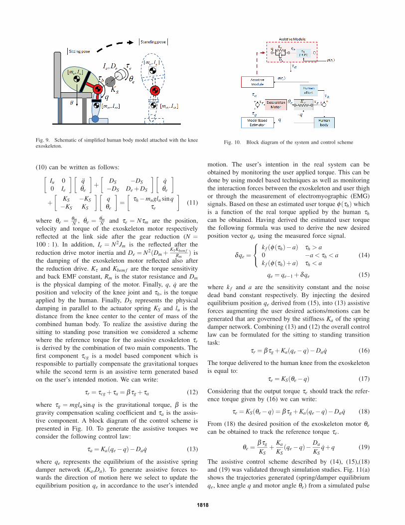
Fig. 9. Schematic of simplified human body model attached with the kneeexoskeleton.
(10) can be written as follows:
[Iu 0
0 Ie
][q̈θ̈e
]+
[DS −DS−DS De +DS
][q̇θ̇e
]
+
[KS −KS−KS KS
][qθe
]=
[τh −muglu sinq
τe
](11)
where θe = θmN , θ̇e = θ̇m
N and τe = Nτm are the position,
velocity and torque of the exoskeleton motor respectively
reflected at the link side after the gear reduction (N =100 : 1). In addition, Ie = N2Jm is the reflected after the
reduction drive motor inertia and De = N2(Dm +Kτ Kbem f
Rm) is
the damping of the exoskeleton motor reflected also after
the reduction drive. Kτ and Kbem f are the torque sensitivity
and back EMF constant, Rm is the stator resistance and Dmis the physical damping of the motor. Finally, q, q̇ are the
position and velocity of the knee joint and τh, is the torque
applied by the human. Finally, DS represents the physical
damping in parallel to the actuator spring KS and lu is the
distance from the knee center to the center of mass of the
combined human body. To realize the assistive during the
sitting to standing pose transition we considered a scheme
where the reference torque for the assistive exoskeleton τris derived by the combination of two main components. The
first component τcg is a model based component which is
responsible to partially compensate the gravitational torques
while the second term is an assistive term generated based
on the user’s intended motion. We can write:
τr = τcg + τa = βτg + τa (12)
where τg = mglu sinq is the gravitational torque, β is the
gravity compensation scaling coefficient and τa is the assis-
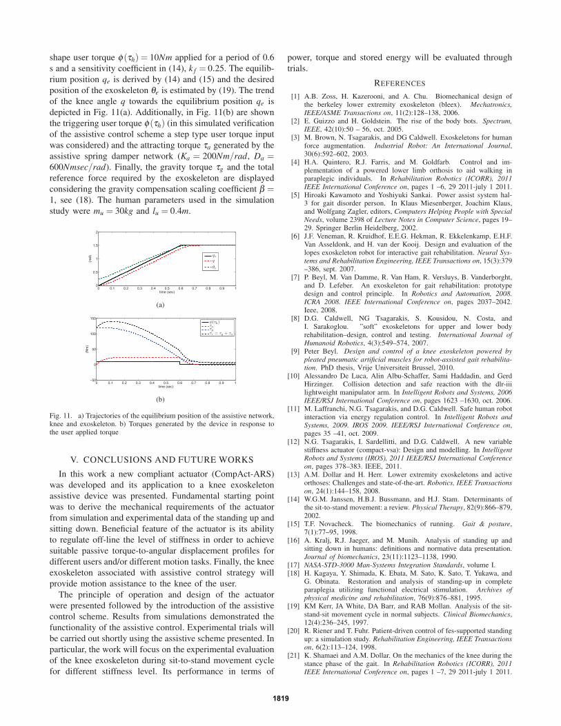
tive component. A block diagram of the control scheme is
presented in Fig. 10. To generate the assistive torques we
consider the following control law:
τa = Ka(qe −q)−Daq̇ (13)
where qe represents the equilibrium of the assistive spring
damper network (Ka,Da). To generate assistive forces to-
wards the direction of motion here we select to update the
equilibrium position qe in accordance to the user’s intended
Fig. 10. Block diagram of the system and control scheme
motion. The user’s intention in the real system can be
obtained by monitoring the user applied torque. This can be
done by using model based techniques as well as monitoring
the interaction forces between the exoskeleton and user thigh
or through the measurement of electromyographic (EMG)
signals. Based on these an estimated user torque φ(τh) which
is a function of the real torque applied by the human τhcan be obtained. Having derived the estimated user torque
the following formula was used to derive the new desired
position vector qe using the measured force signal.
δqe =
⎧⎨⎩
k f (φ(τh)−a) τh > a0 −a < τh < ak f (φ(τh)+a) τh < a
(14)
qe = qe−1 +δqe (15)
where k f and a are the sensitivity constant and the noise
dead band constant respectively. By injecting the desired
equilibrium position qe derived from (15), into (13) assistive
forces augmenting the user desired actions/motions can be
generated that are governed by the stiffness Ka of the spring
damper network. Combining (13) and (12) the overall control
law can be formulated for the sitting to standing transition
task:
τr = βτg +Ka(qe −q)−Daq̇ (16)
The torque delivered to the human knee from the exoskeleton
is equal to:
τe = KS(θe −q) (17)
Considering that the output torque τe should track the refer-
ence torque given by (16) we can write:
τe = KS(θe −q) = βτg +Ka(qe −q)−Daq̇ (18)
From (18) the desired position of the exoskeleton motor θecan be obtained to track the reference torque τe.
θe =βτg
KS+
Ka
KS(qe −q)− Da
KSq̇+q (19)
The assistive control scheme described by (14), (15),(18)
and (19) was validated through simulation studies. Fig. 11(a)
shows the trajectories generated (spring/damper equilibrium
qe, knee angle q and motor angle θe) from a simulated pulse
1818
shape user torque φ(τh) = 10Nm applied for a period of 0.6
s and a sensitivity coefficient in (14), k f = 0.25. The equilib-
rium position qe is derived by (14) and (15) and the desired
position of the exoskeleton θe is estimated by (19). The trend
of the knee angle q towards the equilibrium position qe is
depicted in Fig. 11(a). Additionally, in Fig. 11(b) are shown
the triggering user torque φ(τh) (in this simulated verification
of the assistive control scheme a step type user torque input
was considered) and the attracting torque τa generated by the
assistive spring damper network (Ka = 200Nm/rad, Da =600Nmsec/rad). Finally, the gravity torque τg and the total
reference force required by the exoskeleton are displayed
considering the gravity compensation scaling coefficient β =1, see (18). The human parameters used in the simulation
study were mu = 30kg and lu = 0.4m.
0 0.1 0.2 0.3 0.4 0.5 0.6 0.7 0.8 0.9 10
0.5
1
1.5
2
time (sec)
(rad
) qeq
θe
(a)
0 0.1 0.2 0.3 0.4 0.5 0.6 0.7 0.8 0.9 1−50
0
50
100
150
time (sec)
(Nm
)
φ(τh)τaτgτr = τg + τa
(b)
Fig. 11. a) Trajectories of the equilibrium position of the assistive network,knee and exoskeleton. b) Torques generated by the device in response tothe user applied torque
V. CONCLUSIONS AND FUTURE WORKS
In this work a new compliant actuator (CompAct-ARS)
was developed and its application to a knee exoskeleton
assistive device was presented. Fundamental starting point
was to derive the mechanical requirements of the actuator
from simulation and experimental data of the standing up and
sitting down. Beneficial feature of the actuator is its ability
to regulate off-line the level of stiffness in order to achieve
suitable passive torque-to-angular displacement profiles for
different users and/or different motion tasks. Finally, the knee
exoskeleton associated with assistive control strategy will
provide motion assistance to the knee of the user.
The principle of operation and design of the actuator
were presented followed by the introduction of the assistive
control scheme. Results from simulations demonstrated the
functionality of the assistive control. Experimental trials will
be carried out shortly using the assistive scheme presented. In
particular, the work will focus on the experimental evaluation
of the knee exoskeleton during sit-to-stand movement cycle
for different stiffness level. Its performance in terms of
power, torque and stored energy will be evaluated through
trials.
REFERENCES
[1] A.B. Zoss, H. Kazerooni, and A. Chu. Biomechanical design ofthe berkeley lower extremity exoskeleton (bleex). Mechatronics,IEEE/ASME Transactions on, 11(2):128–138, 2006.
[2] E. Guizzo and H. Goldstein. The rise of the body bots. Spectrum,IEEE, 42(10):50 – 56, oct. 2005.
[3] M. Brown, N. Tsagarakis, and DG Caldwell. Exoskeletons for humanforce augmentation. Industrial Robot: An International Journal,30(6):592–602, 2003.
[4] H.A. Quintero, R.J. Farris, and M. Goldfarb. Control and im-plementation of a powered lower limb orthosis to aid walking inparaplegic individuals. In Rehabilitation Robotics (ICORR), 2011IEEE International Conference on, pages 1 –6, 29 2011-july 1 2011.
[5] Hiroaki Kawamoto and Yoshiyuki Sankai. Power assist system hal-3 for gait disorder person. In Klaus Miesenberger, Joachim Klaus,and Wolfgang Zagler, editors, Computers Helping People with SpecialNeeds, volume 2398 of Lecture Notes in Computer Science, pages 19–29. Springer Berlin Heidelberg, 2002.
[6] J.F. Veneman, R. Kruidhof, E.E.G. Hekman, R. Ekkelenkamp, E.H.F.Van Asseldonk, and H. van der Kooij. Design and evaluation of thelopes exoskeleton robot for interactive gait rehabilitation. Neural Sys-tems and Rehabilitation Engineering, IEEE Transactions on, 15(3):379–386, sept. 2007.
[7] P. Beyl, M. Van Damme, R. Van Ham, R. Versluys, B. Vanderborght,and D. Lefeber. An exoskeleton for gait rehabilitation: prototypedesign and control principle. In Robotics and Automation, 2008.ICRA 2008. IEEE International Conference on, pages 2037–2042.Ieee, 2008.
[8] D.G. Caldwell, NG Tsagarakis, S. Kousidou, N. Costa, andI. Sarakoglou. ”soft” exoskeletons for upper and lower bodyrehabilitation–design, control and testing. International Journal ofHumanoid Robotics, 4(3):549–574, 2007.
[9] Peter Beyl. Design and control of a knee exoskeleton powered bypleated pneumatic artificial muscles for robot-assisted gait rehabilita-tion. PhD thesis, Vrije Universiteit Brussel, 2010.
[10] Alessandro De Luca, Alin Albu-Schaffer, Sami Haddadin, and GerdHirzinger. Collision detection and safe reaction with the dlr-iiilightweight manipulator arm. In Intelligent Robots and Systems, 2006IEEE/RSJ International Conference on, pages 1623 –1630, oct. 2006.
[11] M. Laffranchi, N.G. Tsagarakis, and D.G. Caldwell. Safe human robotinteraction via energy regulation control. In Intelligent Robots andSystems, 2009. IROS 2009. IEEE/RSJ International Conference on,pages 35 –41, oct. 2009.
[12] N.G. Tsagarakis, I. Sardellitti, and D.G. Caldwell. A new variablestiffness actuator (compact-vsa): Design and modelling. In IntelligentRobots and Systems (IROS), 2011 IEEE/RSJ International Conferenceon, pages 378–383. IEEE, 2011.
[13] A.M. Dollar and H. Herr. Lower extremity exoskeletons and activeorthoses: Challenges and state-of-the-art. Robotics, IEEE Transactionson, 24(1):144–158, 2008.
[14] W.G.M. Janssen, H.B.J. Bussmann, and H.J. Stam. Determinants ofthe sit-to-stand movement: a review. Physical Therapy, 82(9):866–879,2002.
[15] T.F. Novacheck. The biomechanics of running. Gait & posture,7(1):77–95, 1998.
[16] A. Kralj, R.J. Jaeger, and M. Munih. Analysis of standing up andsitting down in humans: definitions and normative data presentation.Journal of biomechanics, 23(11):1123–1138, 1990.
[17] NASA-STD-3000 Man-Systems Integration Standards, volume I.[18] H. Kagaya, Y. Shimada, K. Ebata, M. Sato, K. Sato, T. Yukawa, and
G. Obinata. Restoration and analysis of standing-up in completeparaplegia utilizing functional electrical stimulation. Archives ofphysical medicine and rehabilitation, 76(9):876–881, 1995.
[19] KM Kerr, JA White, DA Barr, and RAB Mollan. Analysis of the sit-stand-sit movement cycle in normal subjects. Clinical Biomechanics,12(4):236–245, 1997.
[20] R. Riener and T. Fuhr. Patient-driven control of fes-supported standingup: a simulation study. Rehabilitation Engineering, IEEE Transactionson, 6(2):113–124, 1998.
[21] K. Shamaei and A.M. Dollar. On the mechanics of the knee during thestance phase of the gait. In Rehabilitation Robotics (ICORR), 2011IEEE International Conference on, pages 1 –7, 29 2011-july 1 2011.
1819