Embed Size (px)
Citation preview
J. Eng. Technol. Educ. (2014) 11(2): 145-158 June 2014
Modeling and Estimating the Effective Elastic Properties of Carbon Nanotube Reinforced Composites by Finite Element Method
Minh-Tai Le, Shyh-Chour Huang*
Department of Mechanical Engineering,
National Kaohsiung University of Applied Sciences, Taiwan *E-mail: [email protected]
Abstract Carbon nanotubes (CNTs) possess extremely high stiffness, strength and resilience, and may provide the
ultimate reinforcing material for the development of nanocomposites. Evaluating the effective elastic properties of
such nanoscale materials is a difficult task. Modelings and simulations using continuum mechanics models can
play significant roles in this development. In this paper, the nanostructure is modeled as a linearly elastic
composite medium, which consists of a homogeneous matrix having hexagonal representative volume elements
(RVEs) and homogeneous cylindrical nanotubes. Formulas to extract the effective elastic constants from solutions
for the RVEs under axial as well as lateral loading conditions are derived based on the continuum mechanics
approach. An extended rule of mixtures is applied to evaluate the effective Young’s moduli for validation of the
proposed model. Numerical examples using the finite element method (FEM) are presented, which demonstrate
that the load carrying capacities of the CNTs in a matrix are significant. For the RVEs with long carbon nanotubes,
better values of stiffness in the axial direction are found, as compared to stiffness in the lateral direction. Also, a
comparative evaluation of both square and hexagonal RVEs with short carbon nanotubes is performed here, which
indicates that the hexagonal RVEs may be the preferred models for obtaining more accurate results. Finally, the
finite element results are compared with the rule of mixtures using formulae. It is found that the results offered by
proposed model, are in close proximity with those obtained by the rule of mixtures.
Keywords: Elastic properties, Carbon nanotubes, Composites, Finite element method (FEM)
1. Introduction Carbon nanotubes, discovered first by Iijima in 1991 [1], possess extremely high stiffness, strength and
resilience, as well as superior electrical and thermal properties, and may become the ultimate reinforcing material
for the development of an entirely new class of composites. Qian [2] found that by adding just 1% (by weight) of
CNTs in a matrix, the stiffness of the composite is increased between 36 and 42% and the tensile strength by 25%.
The load transfer mechanism of CNTs in nanocomposites has also been demonstrated experimentally [2, 3], and
preliminary simulations have been offered by Chen and Liu [4, 5]. The measured specific tensile strength of a
single layer of a multiwalled carbon nanotube can be as high as 100 times that of steel, and the graphene sheet
(in-plane) is as stiff as diamond at a low strain. These mechanical properties motivate further study of possible
applications for lightweight and high-strength materials.
The concept of unit cells or representative volume elements (RVEs), which has been applied successfully in
the studies of conventional fiber-reinforced composites at the micro scale, is extended to the study of
CNT-reinforced composites at the nanoscale. In this unit cell or RVE approach, a single nanotube with surrounding
Journal of Engineering Technology and Education, ISSN 1813-3851
Minh-Tai Le, Shyh-Chour Huang 146
matrix material can be modeled, with properly applied boundary and interface conditions to account for the effects
of the surrounding material. This RVE model can be employed to study the interactions of the nanotube with the
matrix, to investigate the load transfer mechanism, or to evaluate the effective elastic properties of the
nanocomposites. For example, the electrical properties of CNTs may be tuned by mechanical deformation. Such
properties are highly useful in the applications of sensors or smart materials. The study of these properties may be
multidisciplinary and may involve various branches of science and engineering [6].
However, much work still needs to be done before the potential of CNT-based composites can be fully
realized in real engineering applications. Evaluating the effective elastic properties of such nanoscale materials is
one of the challenging tasks for the development of nanocomposites. Computational approaches, based on the
molecular dynamics (MD) approach (for smaller scales) and continuum mechanics approach (for larger scales),
can play significant roles in the areas of characterizing CNT-based composites [7].
The MD approach has provided abundant simulation results for understanding the behaviors of individual and
bundled CNTs [8–13]. However, in nanocomposite studies, MD simulations of CNTs are currently limited to very
short length and time scales and cannot deal with the larger length scales. Nanocomposites for engineering
applications must expand from nano- to micro- and, eventually, to macro-length scales. Therefore, continuum
mechanics models can be applied initially for simulating the mechanical responses of CNTs in a matrix, as has
been done in [5,7] in studies on the overall responses of CNT composites, before efficient large multiscale models
are established.
The continuum mechanics approach has been employed for quite some time in studies of the mechanical
properties of individual CNTs or CNT bundles. The validity of the continuum approach in the modeling of CNTs is
still not fully established, and its practice will continue to be questioned for some time to come. However, at
present, it seems to be the only feasible approach for obtaining preliminary results for characterizing CNT-based
composites using modeling and simulations. The best argument for using this continuum approach for now is
simply the fact that it has been applied successfully for studying single or bundled CNTs, as given in Refs. [14–16].
In these studies, the CNTs are considered as homogeneous and isotropic materials using a continuum beam, shell,
as well as 3-D solid models, in the analyses of the deformation, buckling and dynamics responses of CNTs.
Material properties, such as equivalent Young’s modulus, Poisson’s ratio and buckling modes of CNTs, have been
successfully predicted by means of these continuum approaches. However, caution should be excised in applying
the continuum approach, as discussed in Ref. [7]. Emphasis should be placed on the overall responses of CNTs or
CNT-based composites, rather than on the local detailed phenomena, such as interfacial stresses or debonding, as
to where the nanoscale MD approach should be employed. Evaluations of the effective elastic properties of
CNT-reinforced composites center on the overall mechanical responses of the RVEs, as presented in Ref. [5]. Thus,
in this study, the continuum approach was deemed adequate, although further development and validation are
needed.
A method based on the elasticity theory for evaluating the effective elastic properties of CNT-based
composites using the representative volume elements (RVEs) (Fig. 1) was established and square RVEs (Fig. 1(a))
investigated in Ref. [4]. Formulas to extract the effective elastic properties from numerical solutions for
cylindrical RVEs under different loads were derived. Analytical results (extended rule of mixtures) based on the
strength of materials theory, used to estimate the effective Young’s modulus in the axial and lateral directions,
which can help validate the numerical solutions, were also derived for both long and short CNT cases in [4].
Modeling and Estimating the Effective Elastic Properties of Carbon Nanotube Reinforced Composites by Finite Element Method
147
Numerical results using the finite element method (FEM) for the square RVEs showed significant increases in the
stiffness in the CNT direction of the nanocomposites under various combinations of CNT and matrix material
properties [4]. However, although square RVEs are easy to use, for which analytical solutions can be derived and
efficient 2-D axisymmetric FEM models applied, they are the most primitive models and can lead to errors due to
the ignoring of materials not covered by the square cells.
In this study, the work initiated in [4] has been extended to hexagonal RVEs (Fig. 1(b)) for the evaluation of
the effective elastic properties of CNT-based composites. New formulas based on the elasticity theory for
extracting the effective elastic properties from solutions of the hexagonal RVEs were derived and numerical
studies using the FEM conducted. The numerical results from the hexagonal RVEs were compared with those
obtained using the square RVEs in [4]. The material properties, Young’s modulus and Poisson’s ratio were
evaluated by changing the CNT end conditions, i.e. both with and without hemispherical cap ends for short CNTs
in the lateral direction. Also, a comparative evaluation of both square and hexagonal RVEs with short carbon
nanotubes is presented here. Finally, the finite element results are compared with the rule of mixtures using
formulae.
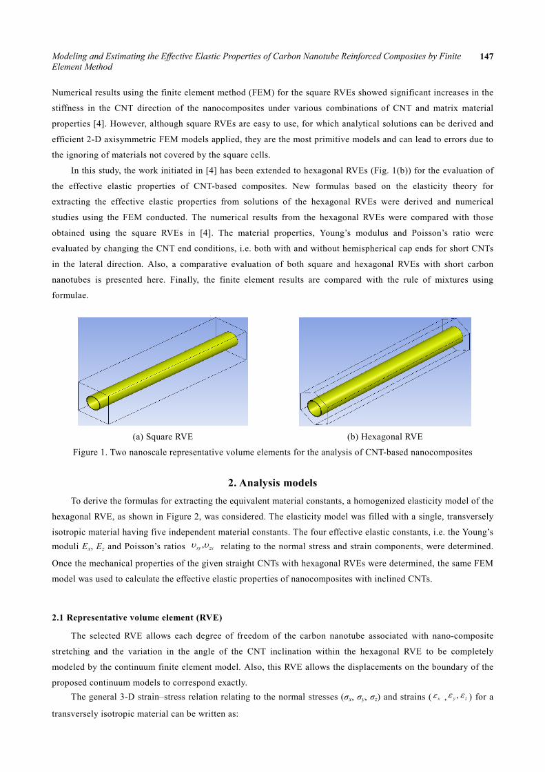
(a) Square RVE (b) Hexagonal RVE
Figure 1. Two nanoscale representative volume elements for the analysis of CNT-based nanocomposites
2. Analysis models To derive the formulas for extracting the equivalent material constants, a homogenized elasticity model of the
hexagonal RVE, as shown in Figure 2, was considered. The elasticity model was filled with a single, transversely
isotropic material having five independent material constants. The four effective elastic constants, i.e. the Young’s moduli Ex, Ez and Poisson’s ratios ,xy zxυ υ relating to the normal stress and strain components, were determined.
Once the mechanical properties of the given straight CNTs with hexagonal RVEs were determined, the same FEM
model was used to calculate the effective elastic properties of nanocomposites with inclined CNTs.
2.1 Representative volume element (RVE)
The selected RVE allows each degree of freedom of the carbon nanotube associated with nano-composite
stretching and the variation in the angle of the CNT inclination within the hexagonal RVE to be completely
modeled by the continuum finite element model. Also, this RVE allows the displacements on the boundary of the
proposed continuum models to correspond exactly. The general 3-D strain–stress relation relating to the normal stresses (σx, σy, σz) and strains ( xε , ,y zε ε ) for a
transversely isotropic material can be written as:
Minh-Tai Le, Shyh-Chour Huang 148
1
1
1
xy zx
x x zx x
xy zxy y
x x zz z
zx zx
z z z
E E E
E E E
E E E
υ υ
ε συ υε σ
ε συ υ
− −
= − −
− −
(1)
To solve four equations for four unknown material constants (Ex, Ez, ,zx xyυ υ ), an axial stretch ΔL and a lateral
load p were considered. The hexagonal RVE was considered to evaluate the four material constants (Ex, Ez, ,zx xyυ υ )
in the axial as well as the lateral direction.
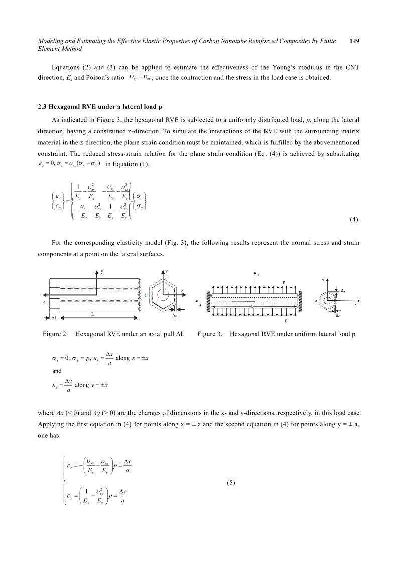
2.2 Hexagonal RVE under an axial stretch ΔL
In this load case, shown in Figure 2, the stress and strain components on the lateral surface are:
0, , along
and along
x y z x
y
L a x aL a
a y aa
σ σ ε ε
ε
∆ ∆= = = = = ±
∆= = ±
where a is the hexagonal base; and Δa is the change of dimension of the cross section under the stretch ΔL in
the z-direction (Δa < 0, if ΔL > 0). Integrating and averaging Equation (3) obtained from Equation (1), after
substituting the values of σx = σy = 0, on the plane Z = L/2, Ez is obtained as:
avez
zz
LEL
σ σε
= =∆ (2)
where the averaged value of stress is given by:
( )ave1 , , / 2zA
x y L dxdyA
σ σ= ∫
with A being the area of the end surface; σave can be evaluated for the RVE using the FEM results. Using the 1st or
2nd expression from Equations (1) and (2), along x = ± a:
zxz z zx
z
L aL a
υε σ υε
∆ ∆= − = − =
Thus, expression for the Poisson’s ratio is obtained as:
( ) ( )/ / /zx a a L Lυ = − ∆ ∆ (3)
Modeling and Estimating the Effective Elastic Properties of Carbon Nanotube Reinforced Composites by Finite Element Method
149
Equations (2) and (3) can be applied to estimate the effectiveness of the Young’s modulus in the CNT direction, Ez and Poison’s ratio zy zxυ υ= , once the contraction and the stress in the load case is obtained.
2.3 Hexagonal RVE under a lateral load p
As indicated in Figure 3, the hexagonal RVE is subjected to a uniformly distributed load, p, along the lateral
direction, having a constrained z-direction. To simulate the interactions of the RVE with the surrounding matrix
material in the z-direction, the plane strain condition must be maintained, which is fulfilled by the abovementioned
constraint. The reduced stress-strain relation for the plane strain condition (Eq. (4)) is achieved by substituting 0, ( )z z zx x yε σ υ σ σ= = + in Equation (1).
2 2
2 2
1
1
xyzx zx
x xx z x z
y yxy zx zx
x z x z
E E E E
E E E E
υυ υε σε συ υ υ
− − − =
− − − (4)
For the corresponding elasticity model (Fig. 3), the following results represent the normal stress and strain
components at a point on the lateral surfaces.
Figure 2. Hexagonal RVE under an axial pull ΔL Figure 3. Hexagonal RVE under uniform lateral load p
0, , along
and
along
x y x
y
xp x aa
y y aa
σ σ ε
ε
∆= = = = ±
∆= = ±
where Δx (< 0) and Δy (> 0) are the changes of dimensions in the x- and y-directions, respectively, in this load case.
Applying the first equation in (4) for points along x = ± a and the second equation in (4) for points along y = ± a,
one has:
(5)
21
xy zxx
x z
zxy
x z
xpE E a
ypE E a
υ υε
υε
∆= − + =
∆ = − =
Minh-Tai Le, Shyh-Chour Huang 150
By solving these two equations, the effective Young’s modulus and Poisson’s ratio in the transverse direction (xy plane) are obtained, in which Ez and zxυ are determined from Equations (2) and (3) of load case 1.
2
1( / ) ( / )x y
zx z
E Ey pa Eυ
= =∆ + (6)
2 2zx zx
xyz z
x ypa E pa E
υ υυ ∆ ∆
= − + +
(7)
Once the changes in dimensions Δx and Δy are determined for the hexagonal RVE, the values of Ex = Ey and xyυ can be computed from Equations (6) and (7), respectively.
3. Rules of mixtures based on the strength of materials theory Simple rules of mixtures can be established based on the strength of materials theory. These rules of mixtures
can be applied to verify the numerical results for the effective Young’s moduli in the CNT axial direction. More
general theories and extended results, in the context of fiber-reinforced composites, can be found in Refs. [17, 18].
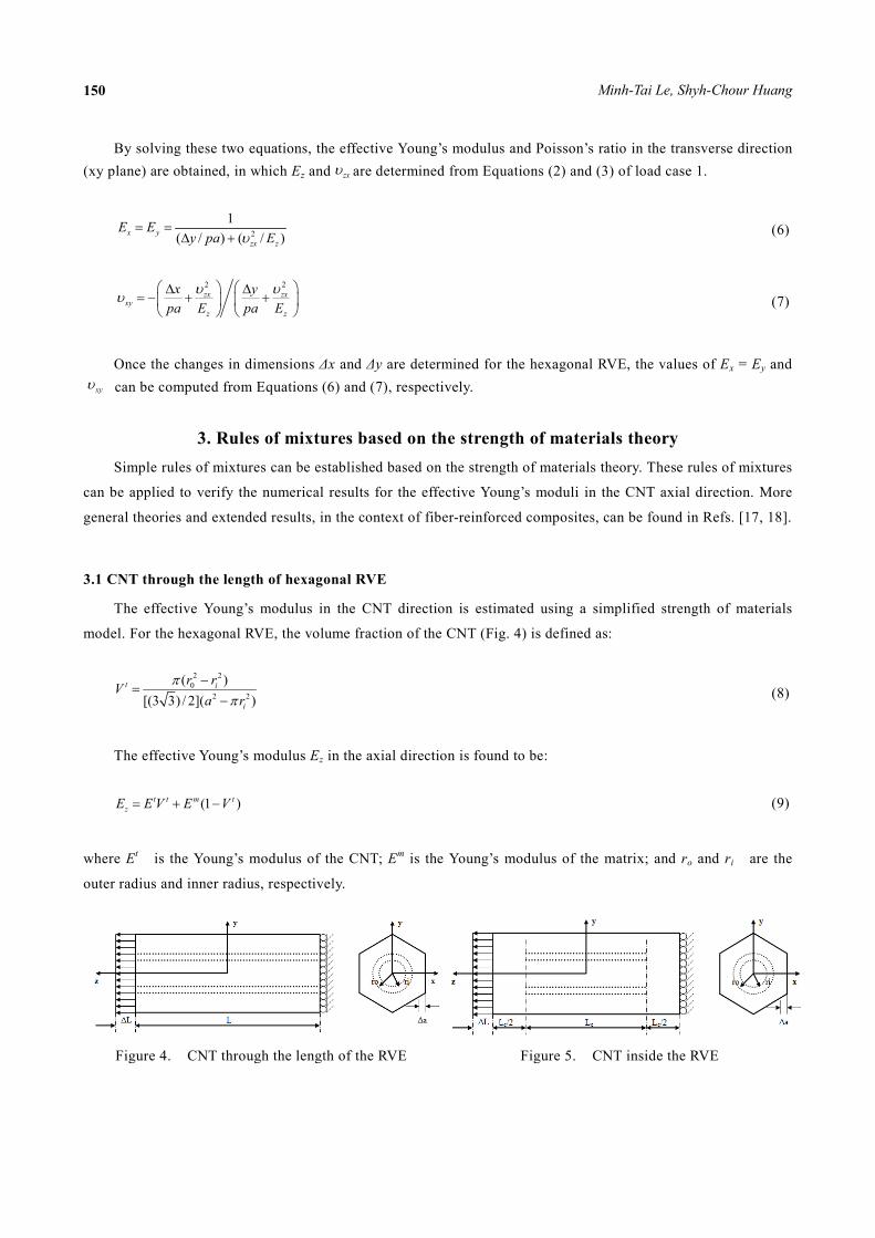
3.1 CNT through the length of hexagonal RVE
The effective Young’s modulus in the CNT direction is estimated using a simplified strength of materials
model. For the hexagonal RVE, the volume fraction of the CNT (Fig. 4) is defined as:
2 20
2 2
( )[(3 3) / 2]( )
t i
i
r rVa r
ππ
−=
− (8)
The effective Young’s modulus Ez in the axial direction is found to be:
(1 )t t m tzE E V E V= + − (9)
where Et is the Young’s modulus of the CNT; Em is the Young’s modulus of the matrix; and ro and ri are the
outer radius and inner radius, respectively.
Figure 4. CNT through the length of the RVE Figure 5. CNT inside the RVE
Modeling and Estimating the Effective Elastic Properties of Carbon Nanotube Reinforced Composites by Finite Element Method
151
3.2 CNT inside the hexagonal RVE
In this case (Fig. 5), the RVE can be divided into two segments: one segment accounting for the two ends
with total length Le and Young’s modulus Em; and the other segment accounting for the center part with length Lc
and an effective Young’s modulus Ec. Note that the two hemispherical end caps of the CNT have been ignored in
this derivation.
Since the center part is a special case of Figure 4, its effective Young’s modulus is found to be:
(1 )c t t m tE E V E V= + − (10)
Using Equation (5), in which the volume fraction of the CNT given by Equation (4) is computed based on the centre part
of the RVE (with length Lc) only, gives:
1 1 1e em c
z c
L L AE E L E L A
= +
(11)
where: 2 2 23 3 / 2, 3 3 / 2c iA L A L rπ= = −
Equations (9) and (11) are applied to compare the FEM estimates of the effective Young’s moduli in the axial
direction.
4. Numerical results and discussion The material properties of the CNT-reinforced composites were investigated for the axial load (Fig. 2) as well
as the lateral load (Fig. 3). Using Equations (2), (3), (6) and (7), the material properties, such as modulus of
elasticity and Poisson’s ratio, were calculated. With various conditions, such as long and short CNTs, with and
without end caps and axial and lateral loading cases, the hexagonal as well as the square RVEs were studied. In the proposed FE analysis, quadratic solid (3D) elements were built in ANSYS for simulation. Prior to the simulation,
we needed to make the measurement non-dimensional, as the scales of CNT are not the same as the general engineering
scales commonly used. The length unit L and force unit F, respectively, are enlarged as follows:
Fansys = 109 Freal ; Lansys = 103 Lreal (12) 9
92 2
1010
ansys realansys real
ansys ansys
F FE EL L
= = =
Subscript ansys means the input and output values in ANSYS, and the subscript real means the real value.
The conversion values of Young’s modulus E can then be deduced.
Although this takes more time to calculate, it enhances the correctness in estimating the mechanical
properties of CNT composites. Before the simulations could start, some basic assumptions for the RVE model
were required: that carbon nanotubes distribute in the matrix uniformly and the aggregation phenomenon will not
happen; and that the CNT and the matrix are the perfect combination.
Minh-Tai Le, Shyh-Chour Huang 152
4.1 A long CNT through the hexagonal RVE under an axial and lateral loading
An hexagonal RVE for a long CNT is considered through the RVE length. The dimensions used are:
For the matrix: length L= 100 nm; hexagonal base a = 11 nm.
For the CNT: length L= 100 nm; outer radius ro = 5 nm; inner radius ri = 4.6 nm.
The Young’s moduli and Poison’s ratio used for the CNT and matrix are:
CNT: Et = 1000 nN/nm2; tυ = 0.3.
Matrix: Em = 200, 100, 20 and 5 nN/nm2; mυ = 0.3.
The values of the dimensions and material constants chosen were within the wide range of those for CNTs as
reported in the literature [19-23].
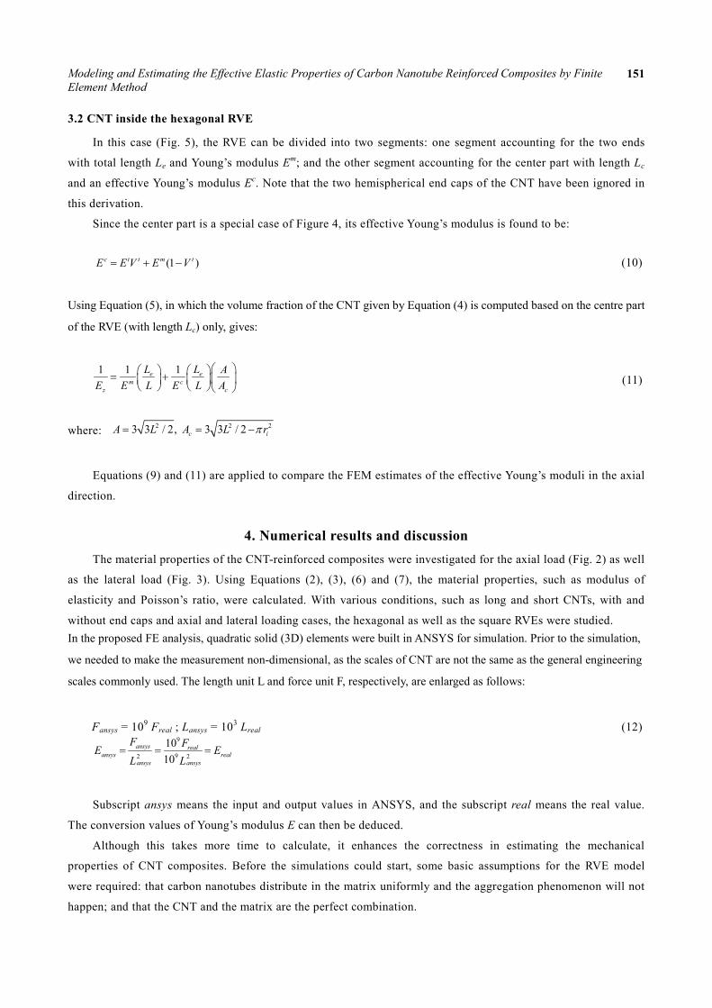
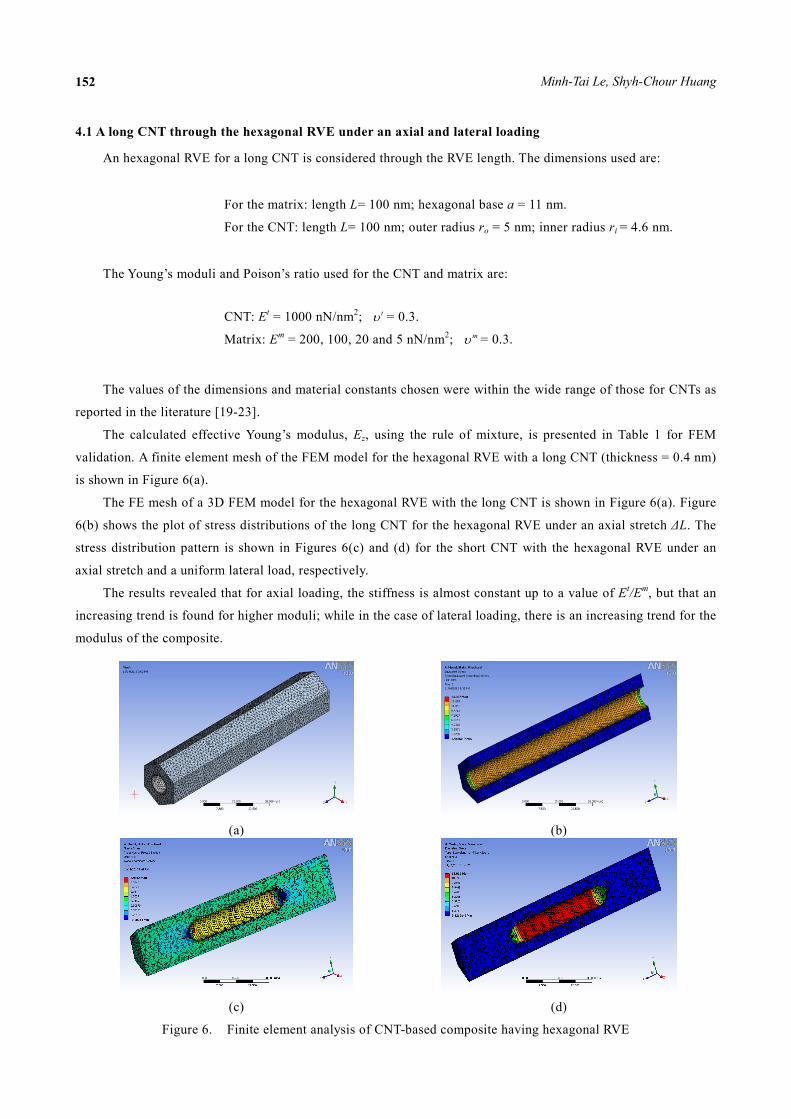
The calculated effective Young’s modulus, Ez, using the rule of mixture, is presented in Table 1 for FEM
validation. A finite element mesh of the FEM model for the hexagonal RVE with a long CNT (thickness = 0.4 nm)
is shown in Figure 6(a).
The FE mesh of a 3D FEM model for the hexagonal RVE with the long CNT is shown in Figure 6(a). Figure
6(b) shows the plot of stress distributions of the long CNT for the hexagonal RVE under an axial stretch ΔL. The
stress distribution pattern is shown in Figures 6(c) and (d) for the short CNT with the hexagonal RVE under an
axial stretch and a uniform lateral load, respectively.
The results revealed that for axial loading, the stiffness is almost constant up to a value of Et/Em, but that an
increasing trend is found for higher moduli; while in the case of lateral loading, there is an increasing trend for the
modulus of the composite.
(a) (b)
(c) (d)
Figure 6. Finite element analysis of CNT-based composite having hexagonal RVE
Modeling and Estimating the Effective Elastic Properties of Carbon Nanotube Reinforced Composites by Finite Element Method
153
Table 1. Calculated effective elastic constants for the long CNT with hexagonal RVE
Et/Em Ez/Em vzx, zy Ex/Em, Ey/Em vxy
FEM ERM FEM FEM ERM FEM ERM
5 1.1894 1.1945 0.3 1.9216 1.9635 1.2392 1.2392
10 1.4134 1.4377 0.3 2.1457 2.1633 0.9749 0.9813
50 3.2050 3.3832 0.3 2.8724 2.8856 0.5286 0.5323
200 9.9234 10.6786 0.3 3.3688 3.3724 0.3920 0.3897
4.2 A short CNT with and without hemispherical end caps inside the hexagonal RVE under axial and lateral
loading
The dimensions for the RVE are the same as in the previous example, except for the total length of the CNT,
which is 50 nm (including the two end hemispherical caps).
Computed effective elastic constants for the CNT inside the hexagonal RVE are listed in Table 2. The strength
of materials solution for the stiffness in the axial direction (Ez), using the extended rule of mixtures (Fig. 5 and Eq.
(11)), is quite close to the FEM solution, which is based on 3-D elasticity, with a difference of only about 1%.
Therefore, the extended rule of mixtures (Eq. (11)) can serve as a quick tool to estimate the stiffness of the
CNT-based composites in the axial direction when the CNTs are relatively short, while a uniform lateral load is
taken care of by Equation (6) and the conventional rule of mixtures (Eq. (9)) can continue to serve in cases when
the CNTs are relatively long.
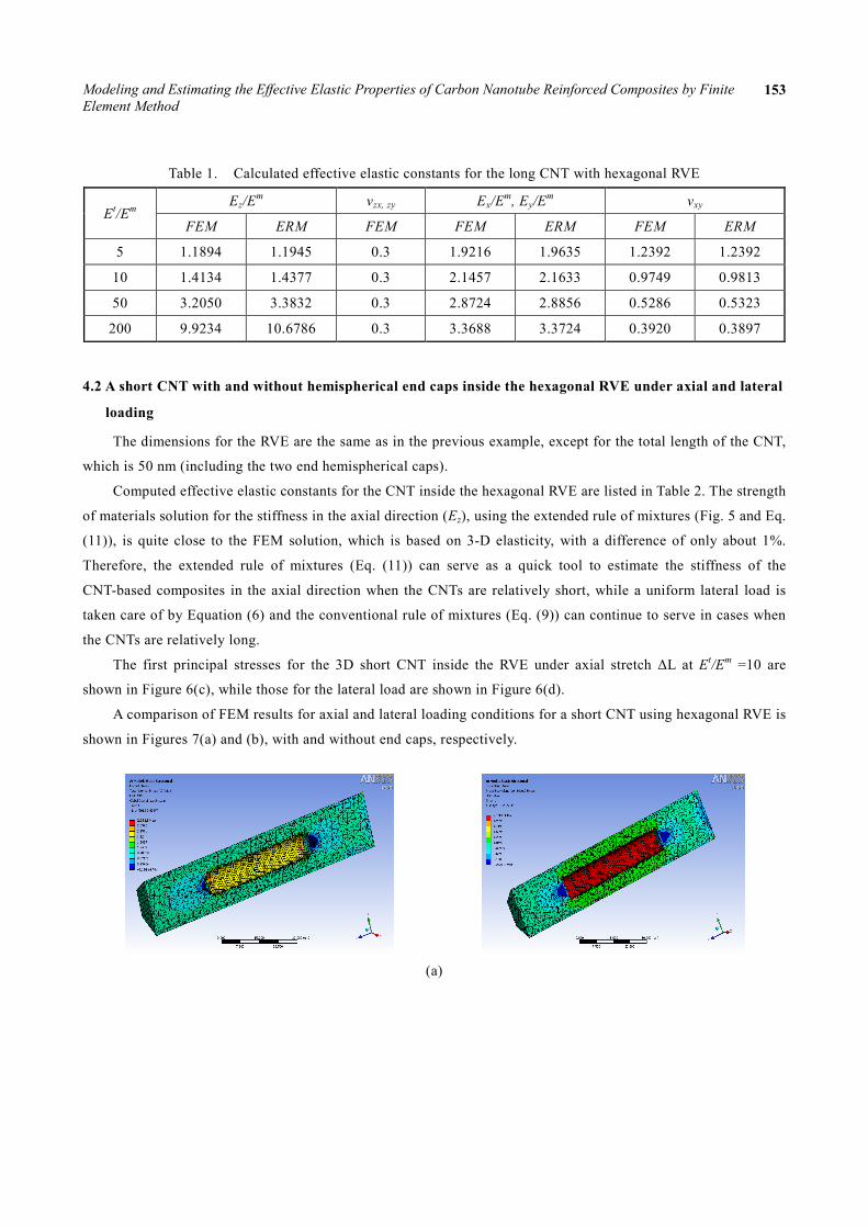
The first principal stresses for the 3D short CNT inside the RVE under axial stretch ΔL at Et/Em =10 are
shown in Figure 6(c), while those for the lateral load are shown in Figure 6(d).
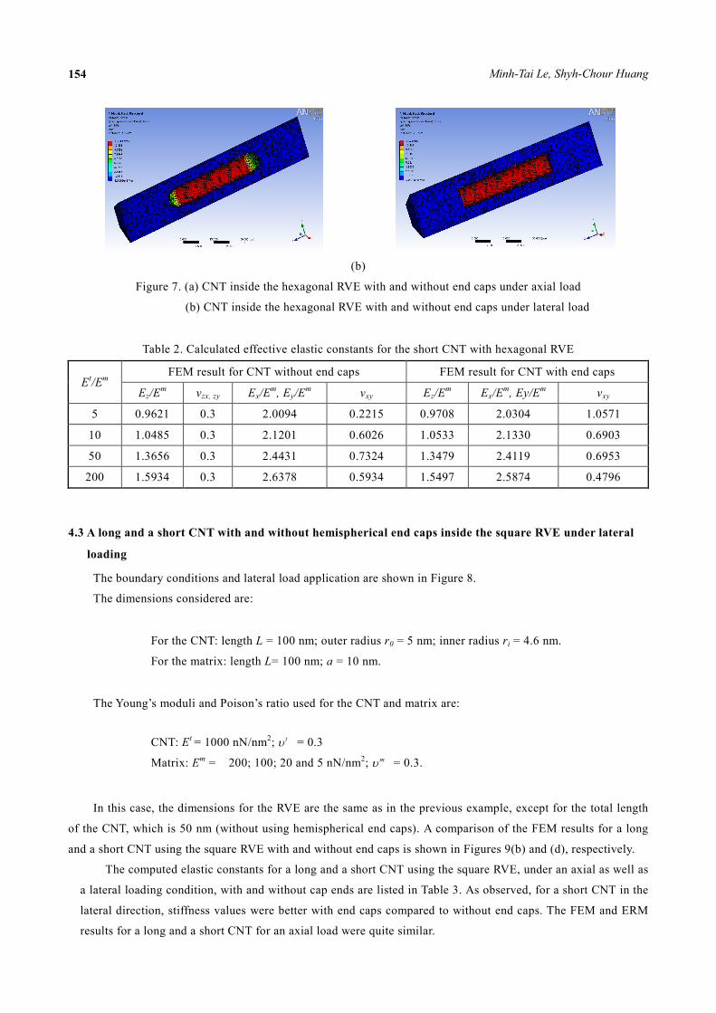
A comparison of FEM results for axial and lateral loading conditions for a short CNT using hexagonal RVE is
shown in Figures 7(a) and (b), with and without end caps, respectively.
(a)
Minh-Tai Le, Shyh-Chour Huang 154
(b)
Figure 7. (a) CNT inside the hexagonal RVE with and without end caps under axial load
(b) CNT inside the hexagonal RVE with and without end caps under lateral load
Table 2. Calculated effective elastic constants for the short CNT with hexagonal RVE
Et/Em FEM result for CNT without end caps FEM result for CNT with end caps
Ez/Em vzx, zy Ex/Em, Ey/Em vxy Ez/Em Ex/Em, Ey/Em vxy
5 0.9621 0.3 2.0094 0.2215 0.9708 2.0304 1.0571
10 1.0485 0.3 2.1201 0.6026 1.0533 2.1330 0.6903
50 1.3656 0.3 2.4431 0.7324 1.3479 2.4119 0.6953
200 1.5934 0.3 2.6378 0.5934 1.5497 2.5874 0.4796
4.3 A long and a short CNT with and without hemispherical end caps inside the square RVE under lateral
loading
The boundary conditions and lateral load application are shown in Figure 8.
The dimensions considered are:
For the CNT: length L = 100 nm; outer radius r0 = 5 nm; inner radius ri = 4.6 nm.
For the matrix: length L= 100 nm; a = 10 nm.
The Young’s moduli and Poison’s ratio used for the CNT and matrix are:
CNT: Et = 1000 nN/nm2; tυ = 0.3
Matrix: Em = 200; 100; 20 and 5 nN/nm2; mυ = 0.3.
In this case, the dimensions for the RVE are the same as in the previous example, except for the total length
of the CNT, which is 50 nm (without using hemispherical end caps). A comparison of the FEM results for a long
and a short CNT using the square RVE with and without end caps is shown in Figures 9(b) and (d), respectively.
The computed elastic constants for a long and a short CNT using the square RVE, under an axial as well as
a lateral loading condition, with and without cap ends are listed in Table 3. As observed, for a short CNT in the
lateral direction, stiffness values were better with end caps compared to without end caps. The FEM and ERM
results for a long and a short CNT for an axial load were quite similar.
Modeling and Estimating the Effective Elastic Properties of Carbon Nanotube Reinforced Composites by Finite Element Method
155
The material properties evaluated with and without end caps showed some differences in FEM results due
to the small change in the effective length.
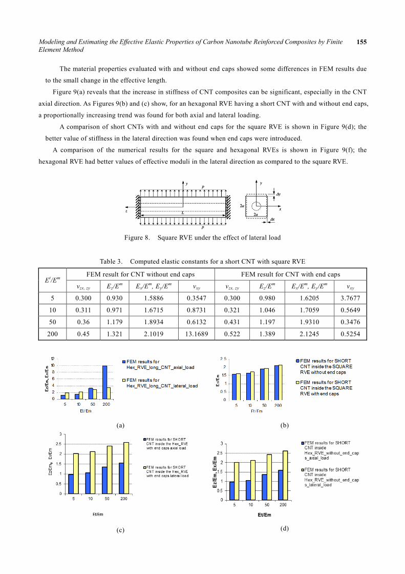
Figure 9(a) reveals that the increase in stiffness of CNT composites can be significant, especially in the CNT
axial direction. As Figures 9(b) and (c) show, for an hexagonal RVE having a short CNT with and without end caps,
a proportionally increasing trend was found for both axial and lateral loading.
A comparison of short CNTs with and without end caps for the square RVE is shown in Figure 9(d); the
better value of stiffness in the lateral direction was found when end caps were introduced.
A comparison of the numerical results for the square and hexagonal RVEs is shown in Figure 9(f); the
hexagonal RVE had better values of effective moduli in the lateral direction as compared to the square RVE.
Figure 8. Square RVE under the effect of lateral load
Table 3. Computed elastic constants for a short CNT with square RVE
Et/Em FEM result for CNT without end caps FEM result for CNT with end caps
vzx, zy Ez/Em Ex/Em, Ey/Em vxy vzx, zy Ez/Em Ex/Em, Ey/Em vxy
5 0.300 0.930 1.5886 0.3547 0.300 0.980 1.6205 3.7677
10 0.311 0.971 1.6715 0.8731 0.321 1.046 1.7059 0.5649
50 0.36 1.179 1.8934 0.6132 0.431 1.197 1.9310 0.3476
200 0.45 1.321 2.1019 13.1689 0.522 1.389 2.1245 0.5254
(a)
(b)
(c)
(d)
Minh-Tai Le, Shyh-Chour Huang 156
0
0.2
0.4
0.6
0.8
1
1.2
1.4
1.6
5 10 50 200
Ez/E
m
Et/Em
FEM results for SHORT CNT inside the SQUARE RVE with end caps
FEM results for SHORT CNT inside the SQUARE RVE without end caps
(e)
(f)
Figure 9. FEM results for a long and a short CNT using an hexagonal RVE and a square RVE under different loads
(a) The comparison between Ex/Em and Ez/Em of hexagonal RVE with long CNTs for different values of Et/Em
(b) The comparison between short CNTs with square matrix under lateral loading, with and without end caps
(c) The variation of Ex/Em and Ez/Em of hexagonal RVE with short CNTs, having end caps for different values of
Et/Em
(d) The variation of Ex/Em and Ez/Em of hexagonal RVE with short CNTs without end caps for different values of
Et/Em
(e) The comparison between short CNT with square matrix under an axial load, with and without end caps
(f) The comparison between square and hexagonal RVEs with long CNTs under uniform lateral load
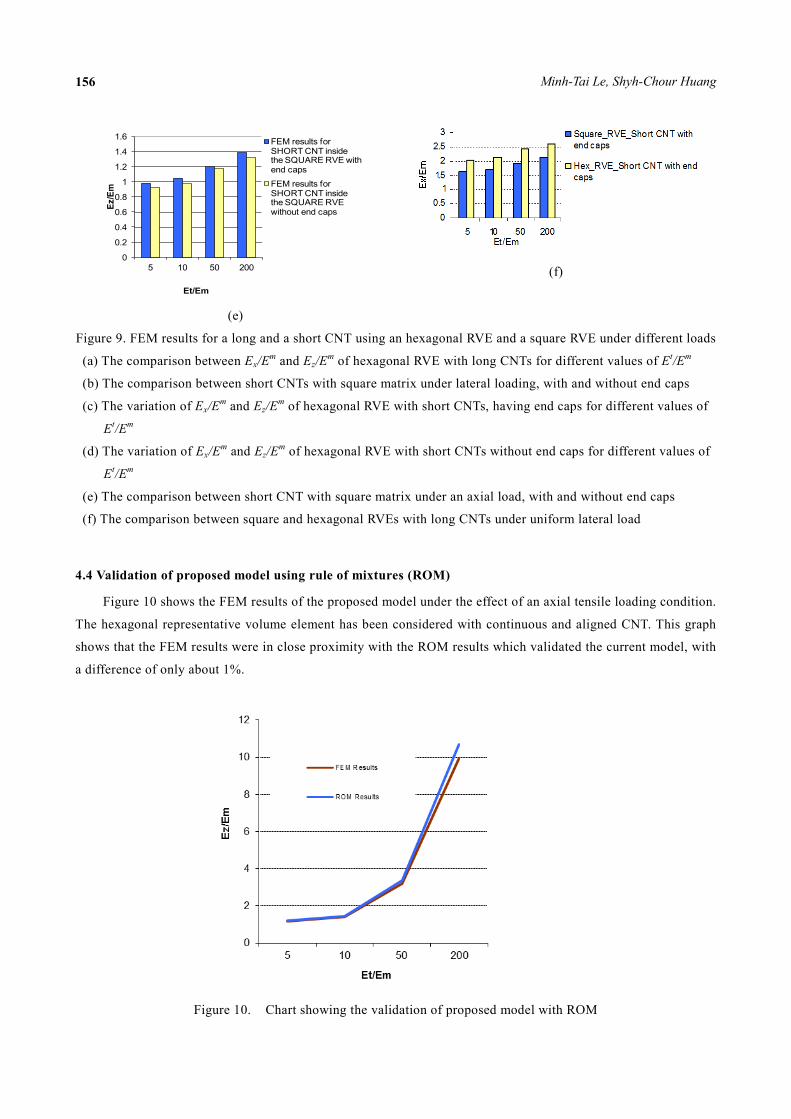
4.4 Validation of proposed model using rule of mixtures (ROM)
Figure 10 shows the FEM results of the proposed model under the effect of an axial tensile loading condition.
The hexagonal representative volume element has been considered with continuous and aligned CNT. This graph
shows that the FEM results were in close proximity with the ROM results which validated the current model, with
a difference of only about 1%.
Figure 10. Chart showing the validation of proposed model with ROM
Modeling and Estimating the Effective Elastic Properties of Carbon Nanotube Reinforced Composites by Finite Element Method
157
5. Conclusions In this paper, we estimated the Young’s modulus and Poisson’s ratio of carbon nanotube (CNT) composites by
using a simulation which combined equivalent homogeneous theory and the finite element method.
Formulas to extract the elastic constants from solutions for the hexagonal and square RVEs under different
loading cases were determined. The rules of mixtures, for both long and short CNT cases, were found to be quite
accurate in estimating the effective Young’s moduli in the CNT axial direction. Numerical examples using the
FEM to evaluate the effective elastic constants of CNT-based composites demonstrated that the reinforcing
capabilities of the CNTs in a matrix are significant.
These simulation results were consistent with the experimental results reported in the literature [24, 25, 26].
Comparison of numerical results for square and hexagonal RVEs revealed that the hexagonal RVE gave better
values of the effective Young’s modulus in the lateral direction. The long CNTs were found to be better
reinforcements than the short CNTs for the composites. For long CNTs, the axial Young’s modulus of elasticity
was found to be higher than that of the modulus in the lateral direction. Finally, the finite element results were
compared with the rule of mixtures using formulae. It was found that the results offered by proposed model, are in
close proximity with those obtained by the rule of mixtures.
In future research, the molecular dynamic (MD) and continuum approach should be integrated with a
multiscale modeling and simulation environment for the analysis of CNT-based composites. More efficient models
of CNTs in a matrix also need to be developed, so that a large number of CNTs, in different shapes and forms
(curved or twisted) or randomly distributed in a matrix, can be modeled.
Reference [1] Iijima, S., “Helical microtubules of graphitic carbon,” Nature, Vol. 354, No. 6348, pp. 56-58, 1991. [2] Qian, D., Liu, W. K. and Ruoff, R. S., “Mechanics of C60 in nanotubes,” Journal of Physics and Chemistry B, Vol. 105,
No. 44, pp. 10753-10758, 2001. [3] Bower, C., Rosen, R., Jin, L., Han, J. and Zhou, O., “Deformation of carbon nanotubes in nanotubepolymer composites,”
Applied Physics Letters, Vol. 74, No. 22, pp. 3317-3319, 1999. [4] Chen, X. L. and Liu, Y. J., “Square representative volume elements for evaluating the effective material properties of
carbon nanotube-based composites,” Computational Materials Science, Vol. 29, No. 1, pp. 1-11, 2004. [5] Liu, Y. J. and Chen, X. L., “Evaluations of the effective materials properties of carbon nanotube-based composites using a
nanoscale representative volume element,” Mechanics of Materials, Vol. 35, No. 1, pp. 69-81, 2003. [6] Ruoff, R. S., Qian, D. and Liu, Y. J., “Mechanical properties of carbon nanotubes: theoretical predictions and
experimental measurements,” Comptes Rendus Physique, Vol. 4, No. 9, pp. 993-1008, 2003. [7] Chen, X. L. and Liu, Y. J., “Continuum models of carbon nanotube-based composites by the BEM,” Electronic Journal of
Boundary Elements, Vol. 1, No. 2, pp. 316-335, 2003. [8] Han, J., Globus, A., Jaffe, R. and Deardorff, G., “Molecular dynamics simulations of carbon nanotube-based gears,”
Nanotechnology, Vol. 8, No. 3, pp. 95-102, 1997. [9] Cornwell, C. F. and Wille, L. T., “Elastic properties of singlewalled carbon nanotubes in compression,” Solid State
Communications, Vol. 101, No. 8, pp. 555-558, 1997. [10] Sinnott, S. B., Shenderova, O.A., White, C. T. and Brenner, D. W., “Mechanical properties of nanotubule fibers and
composites determined from theoretical calculations and simulations,” Carbon, Vol. 36, No. 1, pp. 1-9, 1998. [11] Halicioglu, T., “Stress calculations for carbon nanotubes,” Thin Solid Films, Vol. 312, No. 1, pp. 11-14, 1998. [12] Buongiorno Nardelli, M., Fattebert, J. L., Orlikowski, D., Roland, C., Zhao, Q. and Bernholc, J., “Mechanical properties,
defects and electronic behavior of carbon nanotubes,” Carbon, Vol. 38, No. 11, pp. 1703-1711, 2000. [13] Kang, J. W. and Hwang, H. J., “Mechanical deformation study of copper nanowire using atomistic simulation,”
Nanotechnology, Vol. 12, No. 3, pp. 295-300, 2001. [14] Wong, E. W., Sheehan, P. E., and Lieber, C. M., “Nanobeam mechanics: Elasticity, strength, and toughness of nanorods
and nanotubes,” Science, Vol. 277, No. 5334, pp. 1971-1975, 1997. [15] Sohlberg, K., Sumpter, B. G., Tuzun, R. E., and Noid, D. W., “Continuum methods of mechanics as a simplified approach
to structural engineering of nanostructures,” Nanotechnology, Vol. 9, No. 1, pp. 30-36, 1998. [16] Govindjee, S. and Sackman, J. L., “On the use of continuum mechanics to estimate the properties of nanotubes,” Solid
State Communications, Vol. 110, No. 4, pp. 227-230, 1999. [17] Hyer, M. W., Stress Analysis of Fiber-Reinforced Composite Materials, first ed., McGraw-Hill, Boston, 1998. [18] Nemat-Nasser, S. and Hori, M., Micromechanics: Overall Properties of Heterogeneous Materials, second ed., Elsevier,
Minh-Tai Le, Shyh-Chour Huang 158
Amsterdam, 1999. [19] Lu, J. P., “Elastic properties of single and multilayered nanotubes, Journal of Physics and Chemistry of Solids,” Vol. 58,
No. 11, pp. 1649-1652, 1997. [20] Krishnan, A., Dujardin, E., Ebbesen, T. W., Yianilos, P. N. and Treacy, M. M. J., “Young’s modulus of single-walled
nanotubes,” Physical Review B-Condensed Matter, Vol. 58, No. 20, pp. 14013-14019, 1998. [21] Yao, N. and Lordi, V., “Young’s modulus of single-walled carbon nanotubes,” Journal of Applied Physics, Vol. 84, No. 4,
pp. 1939-1943, 1998. [22] Goze, C., Bernier, P., Henrard, L., Vaccarini, L., Hernandez, E. and Rubio, A., “Elastic and mechanical properties of
carbon nanotubes,” Synthetic Metals, Vol. 103, No. 1, pp. 2500-2501, 1999. [23] Salvetat, J. P., Bonard, J. M., Thomson, N. H., Kulik, A. J., Forro, L., Benoit, W. and Zuppiroli, L., “Mechanical
properties of carbon nanotubes,” Applied Physics A-Materials Science and Processing, Vol. 69, No. 3, pp. 255-260, 1999. [24] Qian, D., Dickey, E. C., Andrews, R., and Rantell, T., “Load transfer and deformation mechanisms in carbon nanotube
polystyrene composites,” Applied Physics Letters, Vol. 76, No. 20, pp. 2868-2870, 2000. [25] Wagner, H. D., Lourie, O., Feldman, Y. and Tenne, R., “Stress-induced fragmentation of multiwall carbon nanotubes in a
polymer matrix,” Applied Physics Letters, Vol. 72, No. 2, pp. 188-190, 1998. [26] Schadler, L. S., Giannaris, S. C., and Ajayan, P. M., “Load transfer in carbon nanotube epoxy composites,” Applied
Physics Letters, Vol. 73, No. 26, pp. 3842-3844, 1998.