Embed Size (px)
Citation preview
1
faimtvqfcpstnsccaocgcn
sa�mvMsopSi
tm
J
C. B. W. Pedersene-mail: [email protected]
N. A. Flecke-mail: [email protected]
Department of Engineering,University of Cambridge,
Trumpington Street,Cambridge, CB2 1PZ,
United Kingdom
G. K. AnanthasureshDepartment of Mechanical Engineering,
Indian Institute of Science,Bangalore 560012,
Indiae-mail: [email protected]
Design of a CompliantMechanism to Modify an ActuatorCharacteristic to Deliver aConstant Output ForceTopology and size optimization methods are used to design compliant mechanisms thatproduce a constant output force for a given actuator characteristic of linearly decreasingforce versus displacement. The design procedure consists of two stages: (i) topologyoptimization using two-dimensional (2-D) continuum parametrization, and (ii) size opti-mization of the beam-element abstraction derived from the continuum topology solution.The examples considered are based upon electrostatic microactuators used widely inmicrosystems. The procedure described here provides conceptual as well as practicallyusable designs for compliant transmission mechanisms with a constant output force char-acteristic. For any given topology design, the maximum achievable constant force over agiven displacement range is determined. Ideal rigid-body and spring-equipped mecha-nisms are analyzed and their features are used to compare with the compliant solutionsobtained. �DOI: 10.1115/1.2218883�
IntroductionMost actuators possess a finite passive stiffness. Consequently,
or a given stimulus to the actuator, such as the applied voltage inn electrostatic actuator, the output force decreases with increas-ng output displacement �i.e., stroke�. Huber et al. �1� have sum-
arized the output force versus output displacement characteris-ics for a wide range of actuators. Most actuators exhibit aariable output force making them unsuitable for applications re-uiring constant force. Applications requiring constant outputorce over a range of displacement include devices to handle deli-ate parts and grips for wear and material testing. Hydraulic andneumatic actuators can provide a constant force, but have limiteduitability, especially in the field of Microelectromechanical Sys-ems �MEMS�. Bell et al. �2�, in their survey of microactuators,ote that the output force typically decreases with increasingtroke. The most widely used microactuator—the electrostaticomb-drive linear actuator—exhibits a linearly, or nonlinearly de-reasing force with increasing output displacement for a givenpplied voltage. A transmission mechanism is needed downstreamf the actuator if it is to be used in constant force applications. Aompliant mechanism can serve this purpose; it can be fully inte-rated into the comb drive without complicating the microfabri-ation process. Related studies on constant force mechanisms areow briefly reviewed.
Constant force mechanisms are not new. For example, Neg’atorprings and other spring-equipped devices are commercially avail-ble. Spring-equipped constant force mechanisms also existNathan �3�; Jenuwine and Midha �4��. In recent years, compliantechanisms, that deliver an almost constant force have been de-
eloped �Howell, Midha, and Murphy �5�; Boyle, Howell,agleby and Evans �6��. These are designed to store energy in
uch a way that the imposed force is almost constant over a rangef displacement. Actively controlled mechanisms are also able torovide constant applied forces of desired magnitude �Nahar andugar �7��. The constant force transmission mechanisms presented
n this paper differ from all of the above in that a constant output
Contributed by the Mechanisms and Robotics Committee of ASME for publica-ion in the JOURNAL OF MECHANICAL DESIGN. Manuscript received June 26, 2005; final
anuscript received December 6, 2005. Review conducted by Larry L. Howell.
ournal of Mechanical Design Copyright © 20
force is achieved over some stroke by conversion of an actuationforce obtained from an actuator of constant stiffness. The level ofoutput force can be made to scale linearly with the stall force ofthe actuator: the mechanism behaves as a passive but smart open-loop transmission device. Since the proposed transmission mecha-nism is a compliant mechanism, its constant force characteristic issufficiently accurate over a prescribed displacement range.
The methodology used to design compliant mechanisms isbriefly reviewed as follows. The topology optimization techniquehas been successfully applied to compliant mechanism design formechanical and nonmechanical actuation stimuli �Ananthasureshet al. �7�; Sigmund �8�; Frecker et al. �9�; Bendsøe and Sigmund�10�; Ananthasuresh �11��. In topology optimization, the design ofthe geometrical form of an elastic structure is posed as a problemof optimal material distribution in a given space. Strategies fortopology optimization for finite deflections are discussed by Brunsand Tortorelli �12�, Pedersen et al. �13�, and Saxena and Anantha-suresh �14�, and more recently by Saxena �15�, who used geneticalgorithms. Pedersen �16–18� also considered the problem of de-signing optimized structures for prescribed energy absorption andcrashworthiness. The methodology adopted in this paper is basedupon some of the above studies with suitable enhancements asrequired. The design variables in most of the published works inthis field are concerned with the fictitious density of continuumelements or sizes or cross-section areas of truss and beam ele-ments. Recently, alternate design parametrizations are being ex-plored �e.g., Zhou and Ting �19�; Wang et al. �20��. In this work,continuum element based and frame element based parametriza-tions are used in two stages to combine the benefits of both.
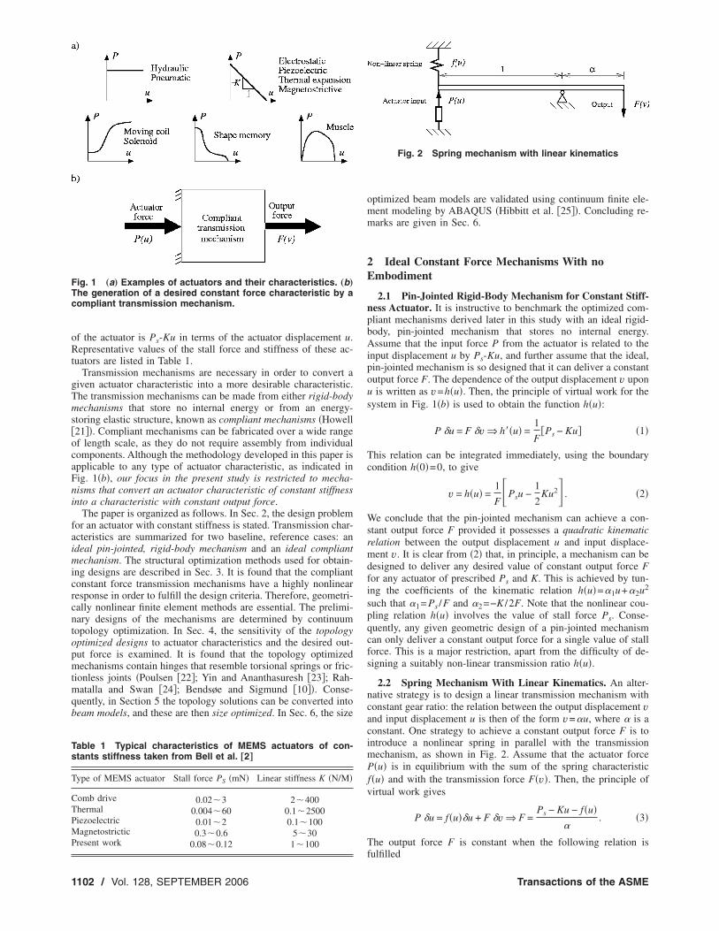
Problem Statement and Outline of Paper. Figure 1�a� showstypical force versus stroke characteristics P�u� of common actua-tors. These are taken from the comprehensive survey of Huber etal. �1�. Except for hydraulic and pneumatic actuators, the outputforce varies with displacement. The internal stiffness of the fol-lowing actuators is constant: electrostatic, piezoelectric, thermalexpansion, and magnetostrictive actuators. Let the stiffness, that isthe linear spring constant, of these actuators be denoted by K. Anddefine the stall force Ps of the actuator as the force it produces at
zero output displacement. The force P available at the output endSEPTEMBER 2006, Vol. 128 / 110106 by ASME
oRt
gTms�ocaFni
faimicrcntopmtmqb
FTc
Ts
T
CTPMP
1
f the actuator is Ps-Ku in terms of the actuator displacement u.epresentative values of the stall force and stiffness of these ac-
uators are listed in Table 1.Transmission mechanisms are necessary in order to convert a
iven actuator characteristic into a more desirable characteristic.he transmission mechanisms can be made from either rigid-bodyechanisms that store no internal energy or from an energy-
toring elastic structure, known as compliant mechanisms �Howell21��. Compliant mechanisms can be fabricated over a wide rangef length scale, as they do not require assembly from individualomponents. Although the methodology developed in this paper ispplicable to any type of actuator characteristic, as indicated inig. 1�b�, our focus in the present study is restricted to mecha-isms that convert an actuator characteristic of constant stiffnessnto a characteristic with constant output force.
The paper is organized as follows. In Sec. 2, the design problemor an actuator with constant stiffness is stated. Transmission char-cteristics are summarized for two baseline, reference cases: andeal pin-jointed, rigid-body mechanism and an ideal compliantechanism. The structural optimization methods used for obtain-
ng designs are described in Sec. 3. It is found that the compliantonstant force transmission mechanisms have a highly nonlinearesponse in order to fulfill the design criteria. Therefore, geometri-ally nonlinear finite element methods are essential. The prelimi-ary designs of the mechanisms are determined by continuumopology optimization. In Sec. 4, the sensitivity of the topologyptimized designs to actuator characteristics and the desired out-ut force is examined. It is found that the topology optimizedechanisms contain hinges that resemble torsional springs or fric-
ionless joints �Poulsen �22�; Yin and Ananthasuresh �23�; Rah-atalla and Swan �24�; Bendsøe and Sigmund �10��. Conse-
uently, in Section 5 the topology solutions can be converted intoeam models, and these are then size optimized. In Sec. 6, the size
ig. 1 „a… Examples of actuators and their characteristics. „b…he generation of a desired constant force characteristic by aompliant transmission mechanism.
able 1 Typical characteristics of MEMS actuators of con-tants stiffness taken from Bell et al. †2‡
ype of MEMS actuator Stall force PS �mN� Linear stiffness K �N/M�
omb drive 0.02�3 2�400hermal 0.004�60 0.1�2500iezoelectric 0.01�2 0.1�100agnetostrictic 0.3�0.6 5�30
resent work 0.08�0.12 1�100
102 / Vol. 128, SEPTEMBER 2006
optimized beam models are validated using continuum finite ele-ment modeling by ABAQUS �Hibbitt et al. �25��. Concluding re-marks are given in Sec. 6.
2 Ideal Constant Force Mechanisms With noEmbodiment
2.1 Pin-Jointed Rigid-Body Mechanism for Constant Stiff-ness Actuator. It is instructive to benchmark the optimized com-pliant mechanisms derived later in this study with an ideal rigid-body, pin-jointed mechanism that stores no internal energy.Assume that the input force P from the actuator is related to theinput displacement u by Ps-Ku, and further assume that the ideal,pin-jointed mechanism is so designed that it can deliver a constantoutput force F. The dependence of the output displacement v uponu is written as v=h�u�. Then, the principle of virtual work for thesystem in Fig. 1�b� is used to obtain the function h�u�:
P �u = F �v Þ h��u� =1
F�Ps − Ku� �1�
This relation can be integrated immediately, using the boundarycondition h�0�=0, to give
v = h�u� =1
F�Psu −
1
2Ku2� . �2�
We conclude that the pin-jointed mechanism can achieve a con-stant output force F provided it possesses a quadratic kinematicrelation between the output displacement u and input displace-ment v. It is clear from �2� that, in principle, a mechanism can bedesigned to deliver any desired value of constant output force Ffor any actuator of prescribed Ps and K. This is achieved by tun-ing the coefficients of the kinematic relation h�u�=�1u+�2u2
such that �1= Ps /F and �2=−K /2F. Note that the nonlinear cou-pling relation h�u� involves the value of stall force Ps. Conse-quently, any given geometric design of a pin-jointed mechanismcan only deliver a constant output force for a single value of stallforce. This is a major restriction, apart from the difficulty of de-signing a suitably non-linear transmission ratio h�u�.
2.2 Spring Mechanism With Linear Kinematics. An alter-native strategy is to design a linear transmission mechanism withconstant gear ratio: the relation between the output displacement vand input displacement u is then of the form v=�u, where � is aconstant. One strategy to achieve a constant output force F is tointroduce a nonlinear spring in parallel with the transmissionmechanism, as shown in Fig. 2. Assume that the actuator forceP�u� is in equilibrium with the sum of the spring characteristicf�u� and with the transmission force F�v�. Then, the principle ofvirtual work gives
P �u = f�u��u + F �v Þ F =Ps − Ku − f�u�
�. �3�
The output force F is constant when the following relation is
Fig. 2 Spring mechanism with linear kinematics
fulfilled
Transactions of the ASME
wtc
Cp
Imt
stbtftcm
3e
tioeem
ssegts
FntIfccocc
J
f�u� = c − Ku Þ F =Ps − c
��4�
here c is an arbitrary constant. We can select the value for c suchhat, over the input stroke of umax, no net energy is stored in theompliant component:
�u=0
u=umax
f�u�du = 0 �5�
onsequently, we take c= Ps /2. With vmax as the prescribed out-ut stroke, we have �=Kvmax/ Ps and the relation �4� reduces to
f�u�Ps
=1
2−
vvmax
ÞF
Ps=
Ps
2Kvmax�6�
t is concluded that the required values of c and � for the springechanism depend upon the choice of actuator stall force Ps and
he output stroke vmax.It is clear that the above ideal mechanisms can deliver a con-
tant output force, but the designs are dictated by the magnitude ofhe actuator force Ps. Structural optimization techniques are usedelow to determine the structural layout of compliant mechanismshat maximize the constant output force F, at fixed input stallorce Ps. The performance of the compliant mechanism for per-urbed values of stall force is also explored. The behavior of theseompliant mechanisms is then compared with the two idealizedechanisms above.
Optimization Strategy For Determining the Geom-try of a Compliant Transmission Mechanism
Our task is to design a transmission mechanism that convertshe actuator displacement u into a suitable output displacement v,deally at a constant output force F. We will relax the constraintsn the design of Sec. 2.2 and allow for nonlinear kinematics withnergy storage in the compliant mechanism. An optimization strat-gy is used to search for geometric designs with the desired trans-ission characteristic.
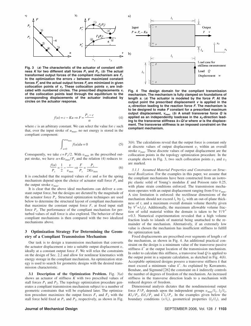
3.1 Description of the Optimization Problem. Fig. 3�a�hows an actuator of stiffness K with two prescribed values oftall forces P1 and P2. The topology optimization procedure gen-rates a compliant transmission mechanism subject to a number ofeometric constraints that will be explained later. The optimiza-ion procedure maximizes the output forces F1 and F2 with the
ig. 3 „a… The characteristic of the actuator of constant stiff-ess K for two different stall forces P1 and P2. „b… The actual
ransformed output forces of the compliant mechanism are Fj.n the optimization the errors � between maximized constantorces Fj
* and the actual output forces Fj are minimized in givenollocation points of vi. These collocation points vi are indi-ated with numbered circles. The prescribed displacements vif the collocation points lead through the equilibrium to theorresponding displacements of the actuator indicated byircles on the actuator response.
tall force held fixed at P1 and P2, respectively, as shown in Fig.
ournal of Mechanical Design
3�b�. The calculations reveal that the output force is constant onlyat discrete values of output displacement vi within an overallstroke vmax. These discrete values of output displacement are thecollocation points in the topology optimization procedure. In theexample shown in Fig. 3, two such collocation points v1 and v2are marked.
3.1.1 Assumed Material Properties and Constraints on Struc-tural Realization. For the examples in this paper, we assume thatthe compliant mechanisms have been constructed from an isotro-pic elastic solid of Young’s modulus E and Poisson ratio 0.25,with plane strain conditions enforced. The transmission mecha-nism operates with an output displacement ranging from 0 to vmax.A size limitation is enforced: the rectilinear dimensions of themechanism should not exceed l1 by l2, with an out-of-plane thick-ness of t, and a maximum overall domain volume thereby givenby V*= l1l2t. Additionally, the maximum allowable volume frac-tion of solid material within the domain is taken to be V /V*
=0.3. Numerical experimentation revealed that a high volumefraction leads to islands of material being unattached to the re-mainder of the mechanism. Alternatively, if an extremely lowvalue is chosen the mechanism has insufficient stiffness to fulfillthe optimization task.
Fixed displacements are prescribed over segments of length s ofthe mechanism, as shown in Fig. 4. An additional practical con-straint on the design is a minimum value of the transverse passivestiffness k* at the output location of the transmission mechanism.In order to calculate this stiffness, a transverse load Q is applied tothe output point in a separate calculation, as sketched in Fig. 4�b�.Acceptable optimized designs possess a transverse stiffness k thatmust exceed a minimum value k*. As explained by Kawamoto,Bendsøe, and Sigmund �26� the constraint on k indirectly controlsthe number of degrees of freedom of the mechanism. An increasedstiffness in the transverse direction leads to a mechanism withreduced degrees of freedom.
Dimensional analysis dictates that the nondimensional outputforce F / Ps depends upon the independent groups vmax/ l1, l2 / l1,Kl1 / Ps, Etl1 / Ps and k*l1 / Ps. In the examples given below the
Fig. 4 The design domain for the compliant transmissionmechanism. The mechanism is fully clamped on foundations oflength s. „a… The actuator is modeled by the force P. At theoutput point the prescribed displacement v is applied in thex1-direction leading to the reaction force F. The mechanism isto be designed to make F constant for a prescribed maximumoutput displacement, vmax. „b… A small transverse force Q isapplied as an independently loadcase in the x2-direction lead-ing to the transverse stiffness k=Q /w where w is the displace-ment. The transverse stiffness is an imposed constraint on thecompliant mechanism.
boundary conditions �s / l1�, geometrical properties �l2 / l1�, and
SEPTEMBER 2006, Vol. 128 / 1103
mptn
oo
Ttdlaoicitmt
Fd
1
aterial parameters �Etl1 / Ps� are held constant. Numerical ex-eriments on the topology optimization reveal the sensitivity ofhe design to the displacement range �vmax/ l1� and actuator stiff-ess �Kl1 / Ps�.
We now explain the structural optimization techniques used tobtain compliant mechanisms having a constant output force Fver a given output stroke vmax.
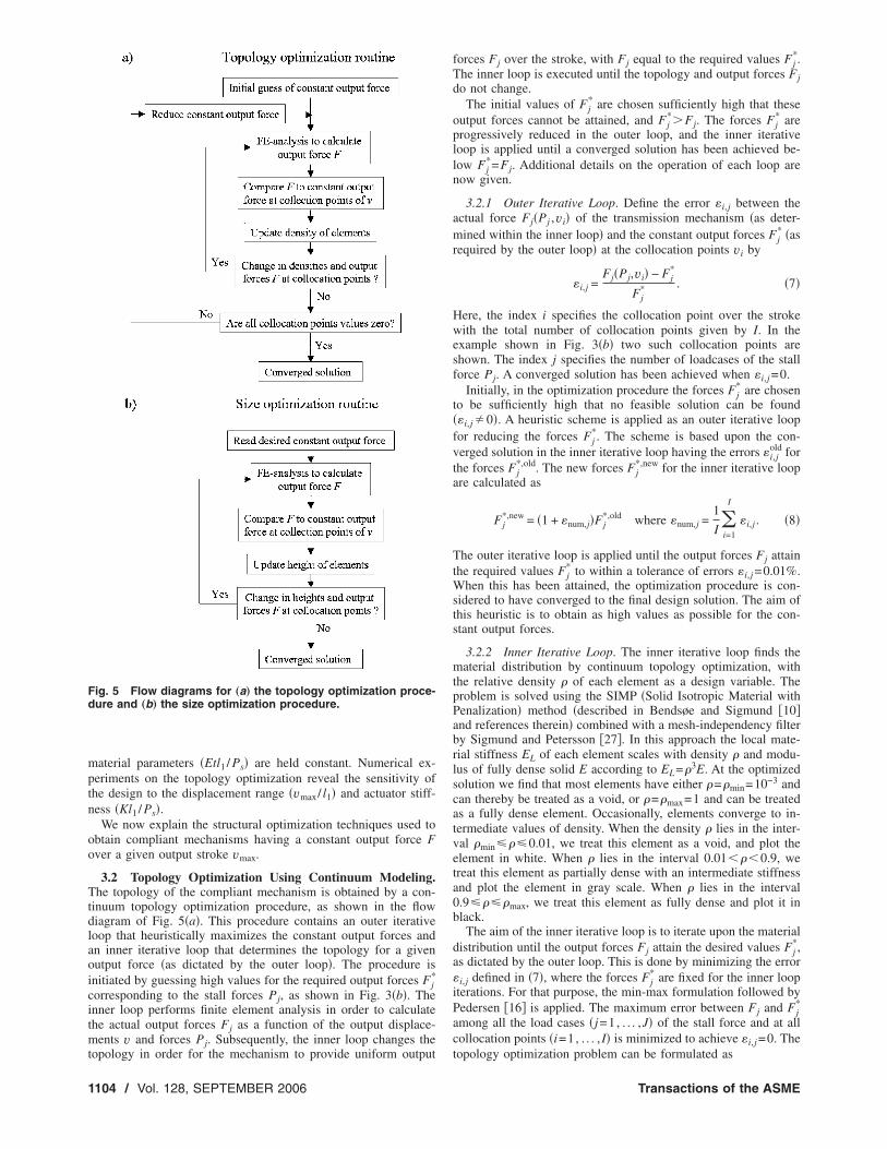
3.2 Topology Optimization Using Continuum Modeling.he topology of the compliant mechanism is obtained by a con-
inuum topology optimization procedure, as shown in the flowiagram of Fig. 5�a�. This procedure contains an outer iterativeoop that heuristically maximizes the constant output forces andn inner iterative loop that determines the topology for a givenutput force �as dictated by the outer loop�. The procedure isnitiated by guessing high values for the required output forces Fj
*
orresponding to the stall forces Pj, as shown in Fig. 3�b�. Thenner loop performs finite element analysis in order to calculatehe actual output forces Fj as a function of the output displace-ents v and forces Pj. Subsequently, the inner loop changes the
ig. 5 Flow diagrams for „a… the topology optimization proce-ure and „b… the size optimization procedure.
opology in order for the mechanism to provide uniform output
104 / Vol. 128, SEPTEMBER 2006
forces Fj over the stroke, with Fj equal to the required values Fj*.
The inner loop is executed until the topology and output forces Fjdo not change.
The initial values of Fj* are chosen sufficiently high that these
output forces cannot be attained, and Fj*�Fj. The forces Fj
* areprogressively reduced in the outer loop, and the inner iterativeloop is applied until a converged solution has been achieved be-low Fj
*=Fj. Additional details on the operation of each loop arenow given.
3.2.1 Outer Iterative Loop. Define the error �i,j between theactual force Fj�Pj ,vi� of the transmission mechanism �as deter-mined within the inner loop� and the constant output forces Fj
* �asrequired by the outer loop� at the collocation points vi by
�i,j =Fj�Pj,vi� − Fj
*
Fj* . �7�
Here, the index i specifies the collocation point over the strokewith the total number of collocation points given by I. In theexample shown in Fig. 3�b� two such collocation points areshown. The index j specifies the number of loadcases of the stallforce Pj. A converged solution has been achieved when �i,j =0.
Initially, in the optimization procedure the forces Fj* are chosen
to be sufficiently high that no feasible solution can be found��i,j�0�. A heuristic scheme is applied as an outer iterative loopfor reducing the forces Fj
*. The scheme is based upon the con-verged solution in the inner iterative loop having the errors �i,j
old forthe forces Fj
*,old. The new forces Fj*,new for the inner iterative loop
are calculated as
Fj*,new = �1 + �num,j�Fj
*,old where �num,j =1
I i=1
I
�i,j . �8�
The outer iterative loop is applied until the output forces Fj attainthe required values Fj
* to within a tolerance of errors �i,j =0.01%.When this has been attained, the optimization procedure is con-sidered to have converged to the final design solution. The aim ofthis heuristic is to obtain as high values as possible for the con-stant output forces.
3.2.2 Inner Iterative Loop. The inner iterative loop finds thematerial distribution by continuum topology optimization, withthe relative density � of each element as a design variable. Theproblem is solved using the SIMP �Solid Isotropic Material withPenalization� method �described in Bendsøe and Sigmund �10�and references therein� combined with a mesh-independency filterby Sigmund and Petersson �27�. In this approach the local mate-rial stiffness EL of each element scales with density � and modu-lus of fully dense solid E according to EL=�3E. At the optimizedsolution we find that most elements have either �=�min=10−3 andcan thereby be treated as a void, or �=�max=1 and can be treatedas a fully dense element. Occasionally, elements converge to in-termediate values of density. When the density � lies in the inter-val �min���0.01, we treat this element as a void, and plot theelement in white. When � lies in the interval 0.01���0.9, wetreat this element as partially dense with an intermediate stiffnessand plot the element in gray scale. When � lies in the interval0.9����max, we treat this element as fully dense and plot it inblack.
The aim of the inner iterative loop is to iterate upon the materialdistribution until the output forces Fj attain the desired values Fj
*,as dictated by the outer loop. This is done by minimizing the error�i,j defined in �7�, where the forces Fj
* are fixed for the inner loopiterations. For that purpose, the min-max formulation followed byPedersen �16� is applied. The maximum error between Fj and Fj
*
among all the load cases �j=1, . . . ,J� of the stall force and at allcollocation points �i=1, . . . , I� is minimized to achieve �i,j =0. The
topology optimization problem can be formulated asTransactions of the ASME
wtbigdRamFsB
sia�ccsnvhgffnfohos
r fu
J
min:max��
���i,j�� for i = 1 = 1, . . . I, j = 1, . . . ,J
subject to :k � k*,
:V � V*,
:0� � ��min � �� � ��max,
:R� = 0�
�9�
here the vector �� contains the design variables. The vectors��min and ��max contain the minimum and maximum values forhe densities, respectively. The transverse stiffness k is constrainedy k*, as shown in Fig. 4�b�. Furthermore, the material volume Vs constraint by V*. The residual for the static equilibrium of theeometrically nonlinear continuum element model, R�= 0�, isetermined using a combined incremental scheme and a Newton-aphson method. The sensitivity information is determined by thedjoint method and the optimization problem is solved using theethod of moving asymptotes �MMA� given in Svanberg �28�.or details about the numerical implementation, see Buhl, Peder-en, and Sigmund �29�, Pedersen, Buhl and Sigmund �13�, andruns and Tortorelli �12�.In topology optimized mechanisms, hinges often occur that re-
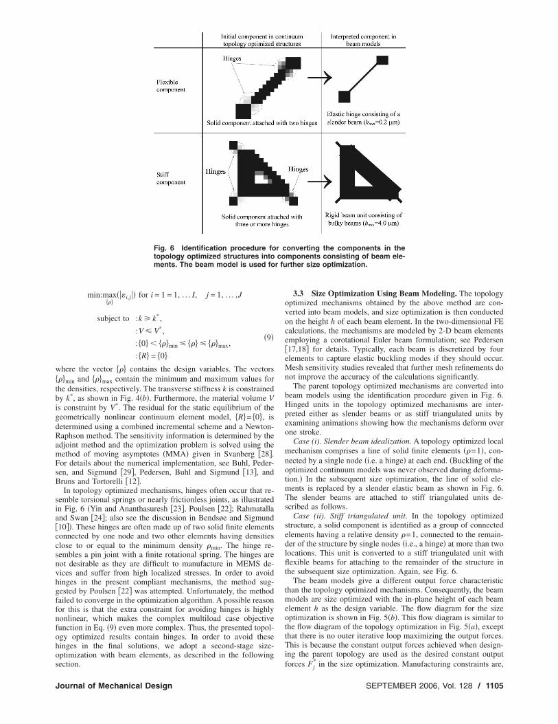
emble torsional springs or nearly frictionless joints, as illustratedn Fig. 6 �Yin and Ananthasuresh �23�, Poulsen �22�; Rahmatalland Swan �24�; also see the discussion in Bendsøe and Sigmund10��. These hinges are often made up of two solid finite elementsonnected by one node and two other elements having densitieslose to or equal to the minimum density �min. The hinge re-embles a pin joint with a finite rotational spring. The hinges areot desirable as they are difficult to manufacture in MEMS de-ices and suffer from high localized stresses. In order to avoidinges in the present compliant mechanisms, the method sug-ested by Poulsen �22� was attempted. Unfortunately, the methodailed to converge in the optimization algorithm. A possible reasonor this is that the extra constraint for avoiding hinges is highlyonlinear, which makes the complex multiload case objectiveunction in Eq. �9� even more complex. Thus, the presented topol-gy optimized results contain hinges. In order to avoid theseinges in the final solutions, we adopt a second-stage size-ptimization with beam elements, as described in the following
Fig. 6 Identification procedure fotopology optimized structures intoments. The beam model is used fo
ection.
ournal of Mechanical Design
3.3 Size Optimization Using Beam Modeling. The topologyoptimized mechanisms obtained by the above method are con-verted into beam models, and size optimization is then conductedon the height h of each beam element. In the two-dimensional FEcalculations, the mechanisms are modeled by 2-D beam elementsemploying a corotational Euler beam formulation; see Pedersen�17,18� for details. Typically, each beam is discretized by fourelements to capture elastic buckling modes if they should occur.Mesh sensitivity studies revealed that further mesh refinements donot improve the accuracy of the calculations significantly.
The parent topology optimized mechanisms are converted intobeam models using the identification procedure given in Fig. 6.Hinged units in the topology optimized mechanisms are inter-preted either as slender beams or as stiff triangulated units byexamining animations showing how the mechanisms deform overone stroke.
Case (i). Slender beam idealization. A topology optimized localmechanism comprises a line of solid finite elements ��=1�, con-nected by a single node �i.e. a hinge� at each end. �Buckling of theoptimized continuum models was never observed during deforma-tion.� In the subsequent size optimization, the line of solid ele-ments is replaced by a slender elastic beam as shown in Fig. 6.The slender beams are attached to stiff triangulated units de-scribed as follows.
Case (ii). Stiff triangulated unit. In the topology optimizedstructure, a solid component is identified as a group of connectedelements having a relative density �=1, connected to the remain-der of the structure by single nodes �i.e., a hinge� at more than twolocations. This unit is converted to a stiff triangulated unit withflexible beams for attaching to the remainder of the structure inthe subsequent size optimization. Again, see Fig. 6.
The beam models give a different output force characteristicthan the topology optimized mechanisms. Consequently, the beammodels are size optimized with the in-plane height of each beamelement h as the design variable. The flow diagram for the sizeoptimization is shown in Fig. 5�b�. This flow diagram is similar tothe flow diagram of the topology optimization in Fig. 5�a�, exceptthat there is no outer iterative loop maximizing the output forces.This is because the constant output forces achieved when design-ing the parent topology are used as the desired constant output
*
onverting the components in themponents consisting of beam ele-rther size optimization.
r cco
forces Fj in the size optimization. Manufacturing constraints are,
SEPTEMBER 2006, Vol. 128 / 1105
hmWriaa
t==dl
wmst�s
4
rmMdclmYecfco
mee1nr
satpno
Ifhfoocsb
1
owever, imposed within the size optimization scheme: a mini-um thickness is imposed on the heights of the beam elements.ith micromachining in mind, the slender beams in Fig. 6 are
estricted to have a minimum height of 0.2 m and the stiff beamsn the almost rigid beam units in Fig. 6 are restricted to havenother minimum height hmin=4 m. Furthermore, the maximumllowable height for all elements is set to hmax=10 m.
The maximum error �7� between the actual output force Fj andhe desired constant output force Fj
* among all the load cases �j1, . . . ,J� of the stall force and at all collocation points �i1, . . . , I� is minimized to achieve �i,j =0, as shown in the flowiagram of Fig. 5�b�. Then the following size optimization prob-em using the heights as design variables can be formulated as
min:maxh�
���i,j�� for i = 1 = 1, . . . I, j = 1, . . . ,J
subject to :k � k*,
:h�min � h� � h�max,
:R� = 0� �10�
here the vector h�min and h�max contain the minimum andaximum value of the heights, respectively. Manufacturing con-
traints are imposed through the constraints h�min and h�max. Theerms k and R� are defined as in �9�. The optimization problem of10� is solved using the modeling and sensitivity analysis as de-cribed in Pedersen �17,18�.
Numerical Examples for Topology OptimizationA set of topology optimizations has been performed, using rep-
esentative values of actuator stiffness K, output stroke vmax, geo-etrical properties l2 and t, and material parameter �E� for currentEMS devices. The design domain is sketched in Fig. 4. The
omain is supported over the length s=10.0 m at the top leftorner and the bottom left corner. The size of the design domain is1=200 m by l2=100 m and the thickness is 10.0 m. Theechanism is to be made from a single crystal or poly silicon ofoung’s modulus 160 GPa and Poisson ratio 0.25. In the presentxample the volume constraint is taken as V /V*=0.3. The volumeonstraint is always active for the present examples. The stallorce Pj and the actuator spring of stiffness K are applied at theenter of the left edge. The prescribed displacement v and theutput force Fj are both applied at the center of the right edge.
The design domain is discretized using four-noded finite ele-ents with bilinear shape functions. Unless otherwise stated, each
lement has a size of 2 m by 2 m, leading to a total of 5000lements. The prescribed output stroke is vmax=2.0 m or0.0 m. The transverse stiffness requirement k* for the mecha-isms is set to be 200 N/m in line with the practical designseviewed by Bell et al. �2�.
In Sec. 4.1 we report on a mechanism optimized for severaltall forces of the actuator. In Sec. 4.2 we explore the effect ofctuator stiffness upon the design, and it contains a mesh sensi-ivity analysis. In Sec. 4.3 the maximum prescribed output dis-lacement range vmax is increased for the transmission mecha-isms. And in Sec. 4.4 the sensitivity of the design to the numberf collocation values of output displacement is determined.
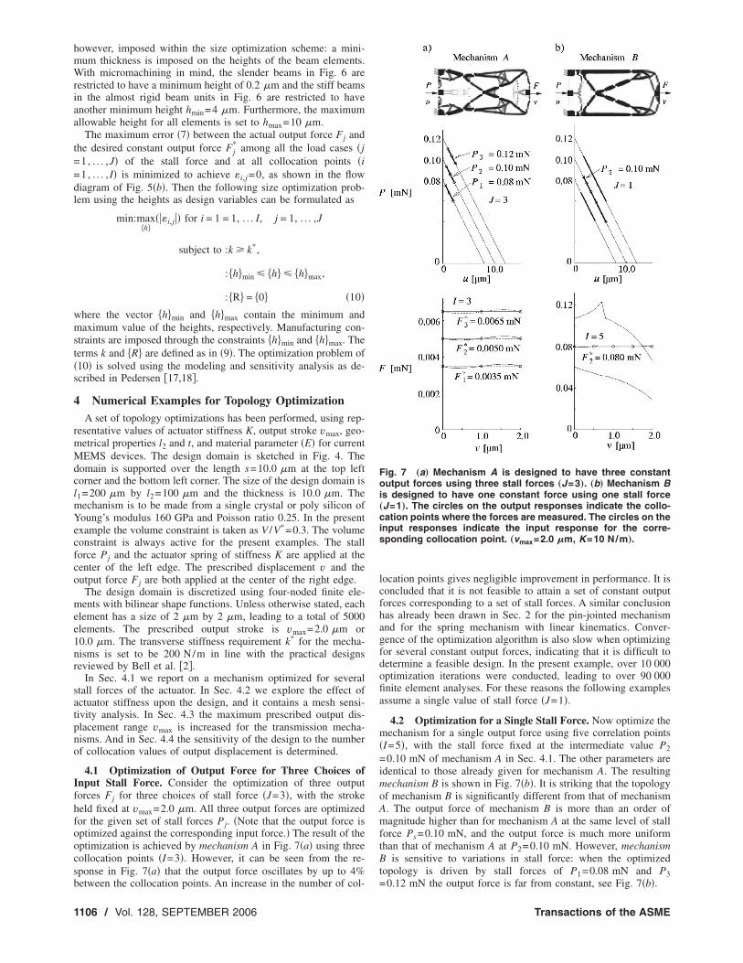
4.1 Optimization of Output Force for Three Choices ofnput Stall Force. Consider the optimization of three outputorces Fj for three choices of stall force �J=3�, with the strokeeld fixed at vmax=2.0 m. All three output forces are optimizedor the given set of stall forces Pj. �Note that the output force isptimized against the corresponding input force.� The result of theptimization is achieved by mechanism A in Fig. 7�a� using threeollocation points �I=3�. However, it can be seen from the re-ponse in Fig. 7�a� that the output force oscillates by up to 4%
etween the collocation points. An increase in the number of col-106 / Vol. 128, SEPTEMBER 2006
location points gives negligible improvement in performance. It isconcluded that it is not feasible to attain a set of constant outputforces corresponding to a set of stall forces. A similar conclusionhas already been drawn in Sec. 2 for the pin-jointed mechanismand for the spring mechanism with linear kinematics. Conver-gence of the optimization algorithm is also slow when optimizingfor several constant output forces, indicating that it is difficult todetermine a feasible design. In the present example, over 10 000optimization iterations were conducted, leading to over 90 000finite element analyses. For these reasons the following examplesassume a single value of stall force �J=1�.
4.2 Optimization for a Single Stall Force. Now optimize themechanism for a single output force using five correlation points�I=5�, with the stall force fixed at the intermediate value P2=0.10 mN of mechanism A in Sec. 4.1. The other parameters areidentical to those already given for mechanism A. The resultingmechanism B is shown in Fig. 7�b�. It is striking that the topologyof mechanism B is significantly different from that of mechanismA. The output force of mechanism B is more than an order ofmagnitude higher than for mechanism A at the same level of stallforce Ps=0.10 mN, and the output force is much more uniformthan that of mechanism A at P2=0.10 mN. However, mechanismB is sensitive to variations in stall force: when the optimizedtopology is driven by stall forces of P1=0.08 mN and P3
Fig. 7 „a… Mechanism A is designed to have three constantoutput forces using three stall forces „J=3…. „b… Mechanism Bis designed to have one constant force using one stall force„J=1…. The circles on the output responses indicate the collo-cation points where the forces are measured. The circles on theinput responses indicate the input response for the corre-sponding collocation point. „vmax=2.0 �m, K=10 N/m….
=0.12 mN the output force is far from constant, see Fig. 7�b�.
Transactions of the ASME
svtoe
FtsTioinwtts
odb=sfpFaFd
Oowwaml�aa
Fft
J
A mesh sensitivity study has been conducted to check if theolution of the topology optimization for mechanism B has con-erged with respect to the mesh discretization. Upon increasinghe number of elements from 5000 to 20 000 the overall topologyf mechanism B did not change and it is concluded that 5000lements suffice.
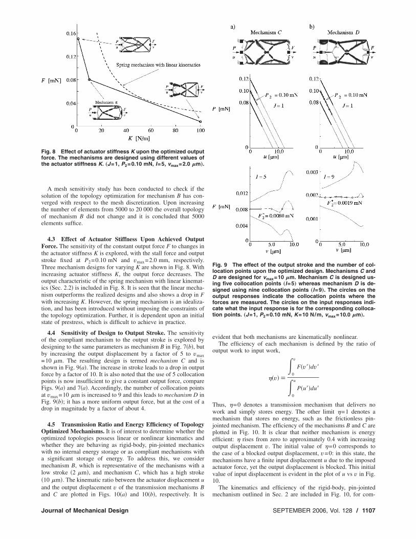
4.3 Effect of Actuator Stiffness Upon Achieved Outputorce. The sensitivity of the constant output force F to changes in
he actuator stiffness K is explored, with the stall force and outputtroke fixed at P2=0.10 mN and vmax=2.0 mm, respectively.hree mechanism designs for varying K are shown in Fig. 8. With
ncreasing actuator stiffness K, the output force decreases. Theutput characteristic of the spring mechanism with linear kinemat-cs �Sec. 2.2� is included in Fig. 8. It is seen that the linear mecha-ism outperforms the realized designs and also shows a drop in Fith increasing K. However, the spring mechanism is an idealiza-
ion, and has been introduced without imposing the constraints ofhe topology optimization. Further, it is dependent upon an initialtate of prestress, which is difficult to achieve in practice.
4.4 Sensitivity of Design to Output Stroke. The sensitivityf the compliant mechanism to the output stroke is explored byesigning to the same parameters as mechanism B in Fig. 7�b�, buty increasing the output displacement by a factor of 5 to vmax10 m. The resulting design is termed mechanism C and is
hown in Fig. 9�a�. The increase in stroke leads to a drop in outputorce by a factor of 10. It is also noted that the use of 5 collocationoints is now insufficient to give a constant output force, compareigs. 9�a� and 7�a�. Accordingly, the number of collocation pointst vmax=10 m is increased to 9 and this leads to mechanism D inig. 9�b�; it has a more uniform output force, but at the cost of arop in magnitude by a factor of about 4.
4.5 Transmission Ratio and Energy Efficiency of Topologyptimized Mechanisms. It is of interest to determine whether the
ptimized topologies possess linear or nonlinear kinematics andhether they are behaving as rigid-body, pin-jointed mechanicsith no internal energy storage or as compliant mechanisms withsignificant storage of energy. To address this, we considerechanism B, which is representative of the mechanisms with a
ow stroke �2 m�, and mechanism C, which has a high stroke10 m�. The kinematic ratio between the actuator displacement und the output displacement v of the transmission mechanisms B
ig. 8 Effect of actuator stiffness K upon the optimized outputorce. The mechanisms are designed using different values ofhe actuator stiffness K. „J=1, P2=0.10 mN, I=5, vmax=2.0 �m….
nd C are plotted in Figs. 10�a� and 10�b�, respectively. It is
ournal of Mechanical Design
evident that both mechanisms are kinematically nonlinear.The efficiency of each mechanism is defined by the ratio of
output work to input work,
�v�
�0
v
F�v��dv�
�0
u
P�u��du�
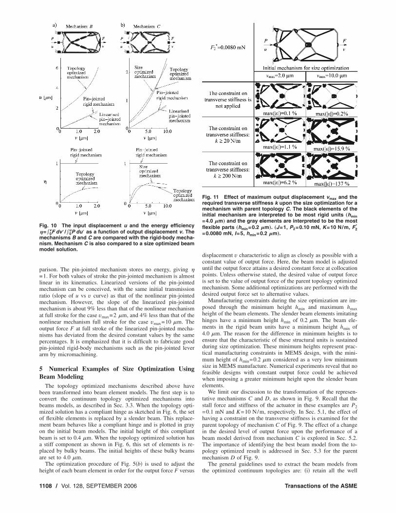
Thus, =0 denotes a transmission mechanism that delivers nowork and simply stores energy. The other limit =1 denotes amechanism that stores no energy, such as the frictionless pin-jointed mechanism. The efficiency of the mechanisms B and C areplotted in Fig. 10. It is clear that neither mechanism is energyefficient: rises from zero to approximately 0.4 with increasingoutput displacement v. The initial value of =0 corresponds tothe case of a blocked output displacement, v=0: in this state, themechanisms have a finite input displacement u due to the imposedactuator force, yet the output displacement is blocked. This initialvalue of input displacement is evident in the plot of u vs v in Fig.10.
The kinematics and efficiency of the rigid-body, pin-jointed
Fig. 9 The effect of the output stroke and the number of col-location points upon the optimized design. Mechanisms C andD are designed for vmax=10 �m. Mechanism C is designed us-ing five collocation points „I=5… whereas mechanism D is de-signed using nine collocation points „I=9…. The circles on theoutput responses indicate the collocation points where theforces are measured. The circles on the input responses indi-cate what the input response is for the corresponding colloca-tion points. „J=1, P2=0.10 mN, K=10 N/m, vmax=10.0 �m….
mechanism outlined in Sec. 2 are included in Fig. 10, for com-
SEPTEMBER 2006, Vol. 128 / 1107
p=lmrmmanonppa
5B
bcbmomobapa
h
F�mnm
1
arison. The pin-jointed mechanism stores no energy, giving 1. For both values of stroke the pin-jointed mechanism is almost
inear in its kinematics. Linearized versions of the pin-jointedechanism can be conceived, with the same initial transmission
atio �slope of u vs v curve� as that of the nonlinear pin-jointedechanism. However, the slope of the linearized pin-jointedechanism is about 9% less than that of the nonlinear mechanism
t full stroke for the case vmax=2 m, and 4% less than that of theonlinear mechanism full stroke for the case vmax=10 m. Theutput force F at full stroke of the linearized pin-jointed mecha-isms has deviated from the desired constant values by the sameercentages. It is emphasized that it is difficult to fabricate goodin-jointed rigid-body mechanisms such as the pin-jointed leverrm by micromachining.
Numerical Examples of Size Optimization Usingeam ModelingThe topology optimized mechanisms described above have
een transformed into beam element models. The first step is toonvert the continuum topology optimized mechanisms intoeams models, as described in Sec. 3.3. When the topology opti-ized solution has a compliant hinge as sketched in Fig. 6, the set
f flexible elements is replaced by a slender beam. This replace-ent beam behaves like a compliant hinge and is plotted in gray
n the initial beam models. The initial height of this complianteam is set to 0.4 m. When the topology optimized solution hasstiff component as shown in Fig. 6, this set of elements is re-
laced by bulky beams. The initial heights of these bulky beamsre set to 4.0 m.
The optimization procedure of Fig. 5�b� is used to adjust the
ig. 10 The input displacement u and the energy efficiency=�0
vF dv� /�0uP du� as a function of output displacement v. The
echanisms B and C are compared with the rigid-body mecha-ism. Mechanism C is also compared to a size optimized beamodel solution.
eight of each beam element in order for the output force F versus
108 / Vol. 128, SEPTEMBER 2006
displacement v characteristic to align as closely as possible with aconstant value of output force. Here, the beam model is adjusteduntil the output force attains a desired constant force at collocationpoints. Unless otherwise stated, the desired value of output forceis set to the value of output force of the parent topology optimizedmechanism. Some additional optimizations are performed with thedesired output force set to alternative values.
Manufacturing constraints during the size optimization are im-posed through the minimum height hmin and maximum hmaxheight of the beam elements. The slender beam elements imitatinghinges have a minimum height hmin of 0.2 m. The beam ele-ments in the rigid beam units have a minimum height hmin of4.0 m. The reason for the difference in minimum heights is toensure that the characteristic of these structural units is sustainedduring size optimization. These minimum heights represent prac-tical manufacturing constraints in MEMS design, with the mini-mum height of hmin=0.2 m considered as a very low minimumsize in MEMS manufacture. Numerical experiments reveal that nofeasible designs with constant output force could be achievedwhen imposing a greater minimum height upon the slender beamelements.
We limit our discussion to the transformation of the represen-tative mechanisms C and D, as shown in Fig. 9. Recall that thestall force and stiffness of the actuator in these examples are P2=0.1 mN and K=10 N/m, respectively. In Sec. 5.1, the effect ofhaving a constraint on the transverse stiffness is examined for theparent topology of mechanism C of Fig. 9. The effect of a changein the desired level of output force upon the performance of abeam model derived from mechanism C is explored in Sec. 5.2.The importance of identifying the best beam model from the to-pology optimized result is addressed in Sec. 5.3 for the parentmechanism D of Fig. 9.
The general guidelines used to extract the beam models from
Fig. 11 Effect of maximum output displacement vmax and therequired transverse stiffness k upon the size optimization for amechanism with parent topology C. The black elements of theinitial mechanism are interpreted to be most rigid units „hmin=4.0 �m… and the gray elements are interpreted to be the mostflexible parts „hmin=0.2 �m…. „J=1, P2=0.10 mN, K=10 N/m, F2
*
=0.0080 mN, I=5, hmin=0.2 �m….
the optimized continuum topologies are: �i� retain all the well
Transactions of the ASME
debaimtsi
vfmotl
5,
J
efined �i.e., black� regions in the exact shape, location, and ori-ntation, �ii� retain the gray regions �except those that excludedelow� that change the topology with minor deviations in shapend orientation, and �iii� ignore the gray regions if they appearnside a relatively rigid frame. Minor deviations in shape are per-
itted in guideline �ii� because gray regions, after size optimiza-ion, lead to flexible segments whose influence is not affected bymall changes in their shape. In guideline �iii�, the gray regionsnside a rigid substructure has little influence on the mechanism.
5.1 Sensitivity of Beam Model Performance to the Trans-erse Stiffness. The beam models contain compliant hinges in theorm of several slender beams. These slender beams attempt toimic the local hinges, as sketched in Fig. 11 in the topology
ptimization solution. Although these slender beams have low ro-ational stiffness they have the deficiency that they also possess a
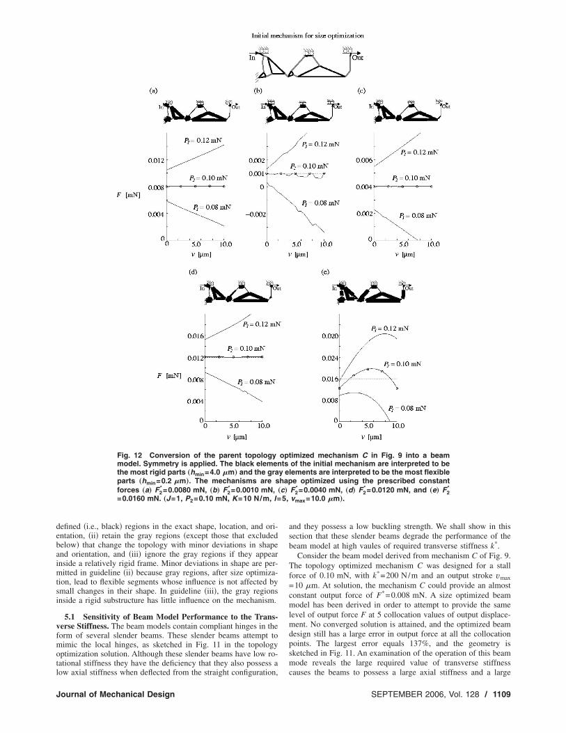
Fig. 12 Conversion of the parent topologymodel. Symmetry is applied. The black elementhe most rigid parts „hmin=4.0 �m… and the graparts „hmin=0.2 �m…. The mechanisms are sforces „a… F2
* =0.0080 mN, „b… F2* =0.0010 mN,
=0.0160 mN. „J=1, P2=0.10 mN, K=10 N/m, I=
ow axial stiffness when deflected from the straight configuration,
ournal of Mechanical Design
and they possess a low buckling strength. We shall show in thissection that these slender beams degrade the performance of thebeam model at high vaules of required transverse stiffness k*.
Consider the beam model derived from mechanism C of Fig. 9.The topology optimized mechanism C was designed for a stallforce of 0.10 mN, with k*=200 N/m and an output stroke vmax=10 m. At solution, the mechanism C could provide an almostconstant output force of F*=0.008 mN. A size optimized beammodel has been derived in order to attempt to provide the samelevel of output force F at 5 collocation values of output displace-ment. No converged solution is attained, and the optimized beamdesign still has a large error in output force at all the collocationpoints. The largest error equals 137%, and the geometry issketched in Fig. 11. An examination of the operation of this beammode reveals the large required value of transverse stiffness
imized mechanism C in Fig. 9 into a beamof the initial mechanism are interpreted to belements are interpreted to be the most flexiblee optimized using the prescribed constant
F2* =0.0040 mN, „d… F2
* =0.0120 mN, and „e… F2*
vmax=10.0 �m….
optts
y ehap„c…
causes the beams to possess a large axial stiffness and a large
SEPTEMBER 2006, Vol. 128 / 1109
bposp
vu=
CiT0=tscs
aca
1
ending stiffness. Consequently, the beam model is not able torovide a constant output force. A reduction in the required valuef k* or a reduction in stroke vmax leads to improved beam de-igns, with a smaller deviation in output force at the collocationoints. This is summarized in Fig. 11.
Subsequently, we relax the requirement of a minimum trans-erse stiffness k* in the beam models. However, we continue tose the topology optimized designs associated with k*
200 N/m as the parent structures for the beam models.
5.2 Ability of a Beam Model to Deliver Desired Values ofonstant Output Force. A size optimized beam model is shown
n Fig. 12�a� derived from the topology optimized mechanism C.he beam model has been optimized for the same stall force of.10 mN, output force of F*=0.008 mN, and output stroke vmax10 m as that of the parent mechanism C. The output force of
he beam model is able to achieve the desired value over the fulltroke, as can be seen in Fig. 12�a�. For completeness, the F vs vharacteristic is shown for a variation in stall force by ±20%. It iseen that F is no longer constant.
The height of the beams are now adjusted by size optimizationt fixed topology and fixed stall force in order to obtain otheronstant values of output force F*. Satisfactory designs that
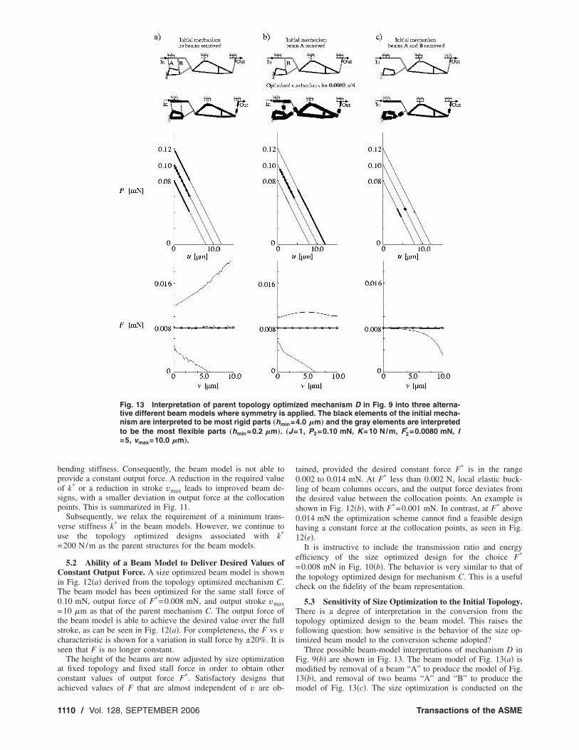
Fig. 13 Interpretation of parent topology opttive different beam models where symmetry isnism are interpreted to be most rigid parts „hm
to be the most flexible parts „hmin=0.2 �m….=5, vmax=10.0 �m….
chieved values of F that are almost independent of v are ob-
110 / Vol. 128, SEPTEMBER 2006
tained, provided the desired constant force F* is in the range0.002 to 0.014 mN. At F* less than 0.002 N, local elastic buck-ling of beam columns occurs, and the output force deviates fromthe desired value between the collocation points. An example isshown in Fig. 12�b�, with F*=0.001 mN. In contrast, at F* above0.014 mN the optimization scheme cannot find a feasible designhaving a constant force at the collocation points, as seen in Fig.12�e�.
It is instructive to include the transmission ratio and energyefficiency of the size optimized design for the choice F*
=0.008 mN in Fig. 10�b�. The behavior is very similar to that ofthe topology optimized design for mechanism C. This is a usefulcheck on the fidelity of the beam representation.
5.3 Sensitivity of Size Optimization to the Initial Topology.There is a degree of interpretation in the conversion from thetopology optimized design to the beam model. This raises thefollowing question: how sensitive is the behavior of the size op-timized beam model to the conversion scheme adopted?
Three possible beam-model interpretations of mechanism D inFig. 9�b� are shown in Fig. 13. The beam model of Fig. 13�a� ismodified by removal of a beam “A” to produce the model of Fig.13�b�, and removal of two beams “A” and “B” to produce the
zed mechanism D in Fig. 9 into three alterna-plied. The black elements of the initial mecha-4.0 �m… and the gray elements are interpreted1, P2=0.10 mN, K=10 N/m, F2
* =0.0080 mN, I
imiap
in=„J=
model of Fig. 13�c�. The size optimization is conducted on the
Transactions of the ASME
tFfmmbmAlHssieltnfrtt
MfibAbtAmP==cltdm
6
cscmeomsTdtz
J
hree beam models of Fig. 13, all for a desired output force of*=0.008 mN. All three models can produce the desired constant
orce at the collocation points. However, the two optimizedechanisms in Figs. 13�a� and 13�c� are not desirable. Theechanism in Fig. 13�a� does not provide a constant output force
etween the prescribed displacement points. Studying the defor-ation of the mechanism in Fig. 13�a� shows that the two beamsand B buckle during the deformation and give rise to the oscil-
ating load response between the displacement collocation points.owever, when the two beams are eliminated in the topology, as
hown in Fig. 13�c�, the size-optimized mechanism behaves as anap-through mechanism. The mechanism in Fig. 13�c� has a largenitial value for the input displacement u of the actuator and en-rgy is stored in the mechanism. The stored energy is then re-eased and the input displacement u remains almost constant whenhe output displacement v is increased. Consequently, this mecha-ism is not desirable. Therefore, only the mechanism in Fig. 13�b�ulfills our design objective. The results in Fig. 13 show that theesults of the size optimization are sensitive to small changes inhe interpretation of the topology obtained by topology optimiza-ion.
5.4 Verification of Size Optimized Transmissionechanisms. The accuracy of the beam models has been con-
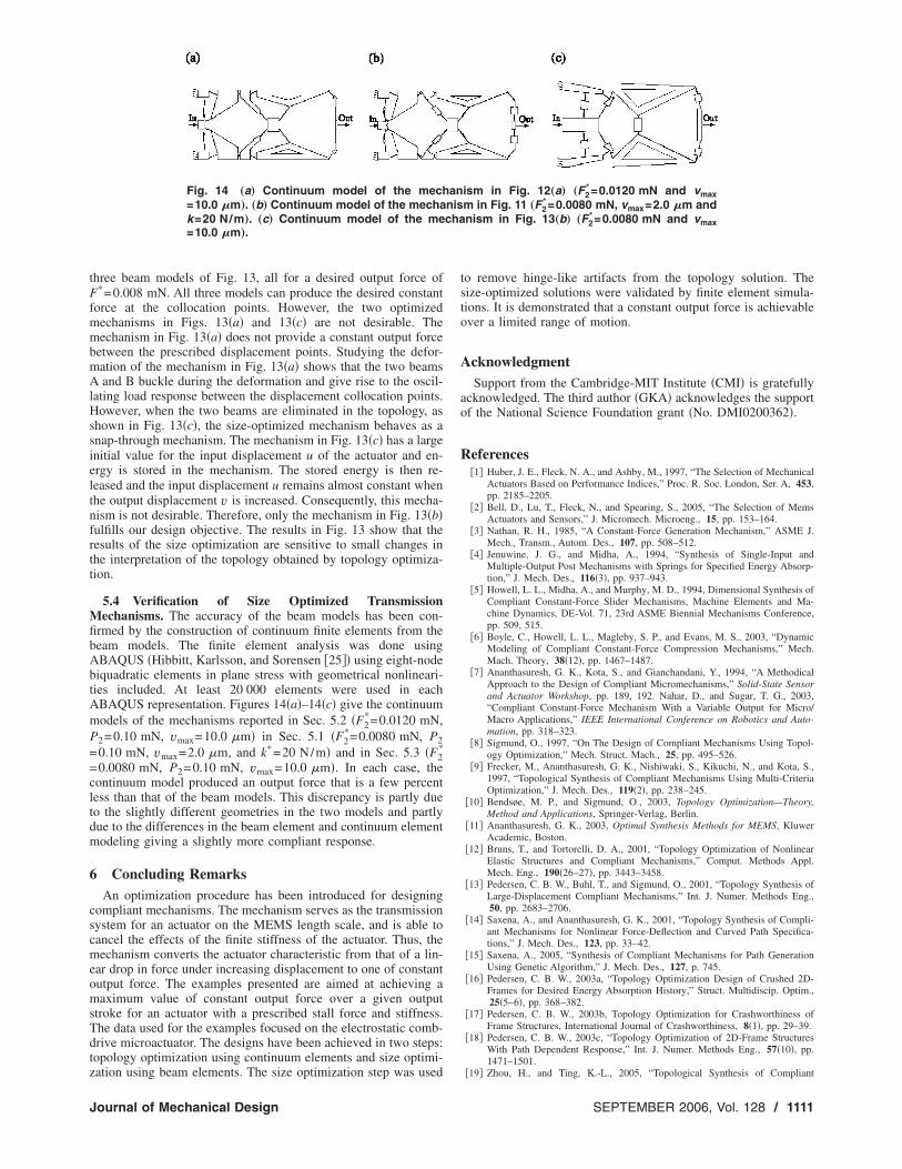
rmed by the construction of continuum finite elements from theeam models. The finite element analysis was done usingBAQUS �Hibbitt, Karlsson, and Sorensen �25�� using eight-nodeiquadratic elements in plane stress with geometrical nonlineari-ies included. At least 20 000 elements were used in eachBAQUS representation. Figures 14�a�–14�c� give the continuumodels of the mechanisms reported in Sec. 5.2 �F2
*=0.0120 mN,
2=0.10 mN, vmax=10.0 m� in Sec. 5.1 �F2*=0.0080 mN, P2
0.10 mN, vmax=2.0 m, and k*=20 N/m� and in Sec. 5.3 �F2*
0.0080 mN, P2=0.10 mN, vmax=10.0 m�. In each case, theontinuum model produced an output force that is a few percentess than that of the beam models. This discrepancy is partly dueo the slightly different geometries in the two models and partlyue to the differences in the beam element and continuum elementodeling giving a slightly more compliant response.
Concluding RemarksAn optimization procedure has been introduced for designing
ompliant mechanisms. The mechanism serves as the transmissionystem for an actuator on the MEMS length scale, and is able toancel the effects of the finite stiffness of the actuator. Thus, theechanism converts the actuator characteristic from that of a lin-
ar drop in force under increasing displacement to one of constantutput force. The examples presented are aimed at achieving aaximum value of constant output force over a given output
troke for an actuator with a prescribed stall force and stiffness.he data used for the examples focused on the electrostatic comb-rive microactuator. The designs have been achieved in two steps:opology optimization using continuum elements and size optimi-
Fig. 14 „a… Continuum model of the mech=10.0 �m…. „b… Continuum model of the mechak=20 N/m…. „c… Continuum model of the me=10.0 �m….
ation using beam elements. The size optimization step was used
ournal of Mechanical Design
to remove hinge-like artifacts from the topology solution. Thesize-optimized solutions were validated by finite element simula-tions. It is demonstrated that a constant output force is achievableover a limited range of motion.
AcknowledgmentSupport from the Cambridge-MIT Institute �CMI� is gratefully
acknowledged. The third author �GKA� acknowledges the supportof the National Science Foundation grant �No. DMI0200362�.
References�1� Huber, J. E., Fleck, N. A., and Ashby, M., 1997, “The Selection of Mechanical
Actuators Based on Performance Indices,” Proc. R. Soc. London, Ser. A, 453,pp. 2185–2205.
�2� Bell, D., Lu, T., Fleck, N., and Spearing, S., 2005, “The Selection of MemsActuators and Sensors,” J. Micromech. Microeng., 15, pp. 153–164.
�3� Nathan, R. H., 1985, “A Constant-Force Generation Mechanism,” ASME J.Mech., Transm., Autom. Des., 107, pp. 508–512.
�4� Jenuwine, J. G., and Midha, A., 1994, “Synthesis of Single-Input andMultiple-Output Post Mechanisms with Springs for Specified Energy Absorp-tion,” J. Mech. Des., 116�3�, pp. 937–943.
�5� Howell, L. L., Midha, A., and Murphy, M. D., 1994, Dimensional Synthesis ofCompliant Constant-Force Slider Mechanisms, Machine Elements and Ma-chine Dynamics, DE-Vol. 71, 23rd ASME Biennial Mechanisms Conference,pp. 509, 515.
�6� Boyle, C., Howell, L. L., Magleby, S. P., and Evans, M. S., 2003, “DynamicModeling of Compliant Constant-Force Compression Mechanisms,” Mech.Mach. Theory, 38�12�, pp. 1467–1487.
�7� Ananthasuresh, G. K., Kota, S., and Gianchandani, Y., 1994, “A MethodicalApproach to the Design of Compliant Micromechanisms,” Solid-State Sensorand Actuator Workshop, pp. 189, 192. Nahar, D., and Sugar, T. G., 2003,“Compliant Constant-Force Mechanism With a Variable Output for Micro/Macro Applications,” IEEE International Conference on Robotics and Auto-mation, pp. 318–323.
�8� Sigmund, O., 1997, “On The Design of Compliant Mechanisms Using Topol-ogy Optimization,” Mech. Struct. Mach., 25, pp. 495–526.
�9� Frecker, M., Ananthasuresh, G. K., Nishiwaki, S., Kikuchi, N., and Kota, S.,1997, “Topological Synthesis of Compliant Mechanisms Using Multi-CriteriaOptimization,” J. Mech. Des., 119�2�, pp. 238–245.
�10� Bendsøe, M. P., and Sigmund, O., 2003, Topology Optimization—Theory,Method and Applications, Springer-Verlag, Berlin.
�11� Ananthasuresh, G. K., 2003, Optimal Synthesis Methods for MEMS, KluwerAcademic, Boston.
�12� Bruns, T., and Tortorelli, D. A., 2001, “Topology Optimization of NonlinearElastic Structures and Compliant Mechanisms,” Comput. Methods Appl.Mech. Eng., 190�26–27�, pp. 3443–3458.
�13� Pedersen, C. B. W., Buhl, T., and Sigmund, O., 2001, “Topology Synthesis ofLarge-Displacement Compliant Mechanisms,” Int. J. Numer. Methods Eng.,50, pp. 2683–2706.
�14� Saxena, A., and Ananthasuresh, G. K., 2001, “Topology Synthesis of Compli-ant Mechanisms for Nonlinear Force-Deflection and Curved Path Specifica-tions,” J. Mech. Des., 123, pp. 33–42.
�15� Saxena, A., 2005, “Synthesis of Compliant Mechanisms for Path GenerationUsing Genetic Algorithm,” J. Mech. Des., 127, p. 745.
�16� Pedersen, C. B. W., 2003a, “Topology Optimization Design of Crushed 2D-Frames for Desired Energy Absorption History,” Struct. Multidiscip. Optim.,25�5–6�, pp. 368–382.
�17� Pedersen, C. B. W., 2003b, Topology Optimization for Crashworthiness ofFrame Structures, International Journal of Crashworthiness, 8�1�, pp. 29–39.
�18� Pedersen, C. B. W., 2003c, “Topology Optimization of 2D-Frame StructuresWith Path Dependent Response,” Int. J. Numer. Methods Eng., 57�10�, pp.1471–1501.
ism in Fig. 12„a… „F2* =0.0120 mN and vmax
m in Fig. 11 „F2* =0.0080 mN, vmax=2.0 �m and
nism in Fig. 13„b… „F2* =0.0080 mN and vmax
annischa
�19� Zhou, H., and Ting, K.-L., 2005, “Topological Synthesis of Compliant
SEPTEMBER 2006, Vol. 128 / 1111
1
Mechanisms Using Spanning Tree Theory,” J. Mech. Des., 127, p. 753.�20� Wang, M. Y., Chen, S., Wang, X., and Mei, Y., 2005, “Design of Multimaterial
Compliant Mechanisms Using Level-Set Methods,” J. Mech. Des., 127, p.941.
�21� Howell, L., 2001, Compliant Mechanisms, Wiley, New York.�22� Poulsen, T. A., 2002, “A Simple Scheme to Prevent Checkerboard Patterns and
One-Node Connected Hinges in Topology Optimization,” Struct. Multidiscip.Optim., 24, pp. 396–399.
�23� Yin, L., and Ananthasuresh, G. K., 2003, “Design of Distributed CompliantMechanisms,” Mech. Based Des. Struct. Mach., 31, pp. 151–179.
�24� Rahmatalla, S., and Swan, C. C., 2005, “Sparse Monolithic Compliant Mecha-nisms Using Continuum Structural Topology Optimization,” Int. J. Numer.
Methods Eng., 62, pp. 1579–1605.112 / Vol. 128, SEPTEMBER 2006
�25� Hibbitt, H. D., Karlsson, B. I., and Sorensen, P., 2001, ABAQUS/StandardUser’s Manual, Version 6.2, Providence, RI.
�26� Kawamoto, A., Bendsøe, M. P., and Sigmund, O., 2004, “Articulated Mecha-nism Design With a Degree of Freedom Constraint,” Int. J. Numer. MethodsEng., 61�9�, pp. 1520–1545.
�27� Sigmund, O., and Petersson, J., 1998, “Numerical Instabilities in TopologyOptimization: A Survey on Procedures Dealing With Checkerboards, Mesh-Dependencies and Local Minima,” Struct. Optim., 16, pp. 68–75.
�28� Svanberg, K., 1987, “The Method of Moving Asymptotes—A New Method forStructural Optimization,” Int. J. Numer. Methods Eng., 24, pp. 359–373.
�29� Buhl, T., Pedersen, C. B. W., and Sigmund, O., 2000, “Stiffness Design ofGeometrically Non-Linear Structures Using Topology Optimization,” Struct.Multidiscip. Optim., 19�2�, pp. 93–104.
Transactions of the ASME