Embed Size (px)
Citation preview
Mechanism and Machine Theory 70 (2013) 225–245
Contents lists available at SciVerse ScienceDirect
Mechanism and Machine Theory
j ourna l homepage: www.e lsev ie r .com/ locate /mechmt\
Dynamic modeling of 3-DOF pyramidal-shapedpiezo-driven mechanism
Vahid Hassani⁎, Tegoeh TjahjowidodoNanyang Technological University, School of Mechanical and Aerospace Engineering, Division of Mechatronics & Design, 50 Nanyang Avenue, 639798, Singapore
a r t i c l e i n f o
⁎ Corresponding author. Tel.: +65 84317280.E-mail address: [email protected] (V. Hassani).
0094-114X/$ – see front matter © 2013 Elsevier Ltd. Ahttp://dx.doi.org/10.1016/j.mechmachtheory.2013.07.
a b s t r a c t
Article history:Received 9 April 2013Received in revised form 15 July 2013Accepted 18 July 2013Available online xxxx
A new pyramidal shaped 3-DOF piezo-driven mechanism is proposed, modeled, manufacturedand tested. The mechanism, made of aluminum alloy (2024-T3), is equipped with threepiezoelectric elements that are separated by 120° angle. This mechanism is designed to deliverelliptical motion in 3-D planes with minimum numbers of actuators subject to differentfrequencies and phase differences applied to the piezoelectric elements. The design procedureis driven based on modal analysis through Finite Element Method (FEM) to ensure that therelevant mode shapes at different planes take place at almost identical frequency.Furthermore, the dynamic modeling of the mechanism is carried out to show that thedesignated structure is able to provide different types of motions at different sets of phasedifferences applied to the three piezoelectric elements. Through dynamic modeling, theresponse at the tip of the mechanism (end effector) is estimated with regard to two types ofdisplacement inputs imposed by piezoceramics at the contact point where the head of thepiezoelectric actuators meets the structure of the mechanism. The two types of displacementinputs are calculated using the newmethodology in terms of constitutive equations utilized formodeling the piezoelectric actuators. These inputs, known as the linear pure sinusoidal inputand the nonlinear hysteretic input, are applied to the contact point in order to compare theresponse on tip of the mechanism to both linear and nonlinear signals.
© 2013 Elsevier Ltd. All rights reserved.
Keywords:Piezo-driven mechanismModal analysisResonanceHysteresisPlanar motion
1. Introduction
In the past three decades, piezoelectric actuators have been playing an important role for high precision mechanisms andmotors which are extensively used in many practical industrial applications such as scanning probe microscopy [1],nanometer-precision piezostepper for ELID-grinding [2], photovoltaic-tracking system to maximize the energy conversion fromsolar radiation [3], innovative positioning methodology using rotary dual-stage actuator [4], minimal invasive surgery devices [5]and hard disk drive positioning system [6]. In addition to the aforementioned applications, rotary piezo-driven motors are alsowidely utilized in many applications such as robot eyes, missile seekers and medical instruments for endoscopic and magneticresonance imaging [7].
Several approaches to deliver planar and rotary motion using piezoactuators are presented in literatures. Shamoto andMoriwaki [8] introduced a walking drive mechanism that exploits nine piezoelectric actuators to generate rotary and linearmotions for a slider on the tip of the mechanism. Devos et al. [9] proposed a planar piezo-driven mechanism by utilization ofmerely four piezoelectric actuators to deliver 3-DOF linear motion to a slider laid on the tip of the mechanism. A complex
ll rights reserved.011
226 V. Hassani, T. Tjahjowidodo / Mechanism and Machine Theory 70 (2013) 225–245
structured XYZ translational compliant parallel micromanipulator is designed by Li and Xu [10] to provide decoupled motionalong x-, y- and z-coordinates.
In a different frame of working, many researchers attempted to model the dynamic behavior of piezo-based mechanisms bothwith regard to piezoelectric effect [11–13] and without it [14–17], particularly for micro/nanopositioning. Polit and Dong [18]proposed a high-bandwidth piezo-driven parallel kinematic nanopositioning XY mechanism. Dynamic analysis of the mechanismshows decoupled motion in XY direction considering its linear behavior.
In this paper, a 3-DOF pyramidal-shaped piezo-driven mechanism is proposed to deliver planar motion in x–y, z–y and x–zplanes. Themechanism is designed to operate in two different modes, i.e. stepping mode, where the mechanism is actuated at lowfrequency to allow high precision positioning and resonant mode, where the system is operated at its resonance frequency inorder to maximize the speed [9]. FEM-based modal analysis [19–21] is carried out to tune the resonance frequency of themechanism at the relevant mode shape. The designated planar motion from the mechanism is produced mainly by introducingphase differences at the three piezoelectric actuators.
Finally, the FE model incorporating the constitutive equations of the piezoelectric materials is derived to verify thedisplacement at the end effector of the mechanism. The dynamic modeling of the mechanism is validated using two prescribedsignals, i.e. pure sinusoidal signal, neglecting the hysteresis phenomenon in the piezoelectric elements, and nonlinear hystereticsignal obtained from the analysis of the hysteretic property on a manufactured proposed mechanism. The validation of themodeling results is carried out by comparing it to the experimental data.
In Section 2, the pyramidal-shaped piezo-drivenmechanism is introduced as a working platform and the motion characteristicof the mechanism is discussed. Subsequently, the analysis of the dynamics of the mechanism is presented in Section 3, by meansof modal analysis and transient dynamics incorporating the hysteresis property of the piezoelectric actuators. Finally, someconclusions are drawn and discussed in the last section.
2. Pyramidal-shaped piezo-driven mechanism
A new piezo-based mechanism is proposed to deliver 3-DOF motion in x–y, z–y and x–z planes. As a main goal, the mechanismis designed to produce motion in any planes with a minimum number of actuators as compared to its counterparts available inliterature.
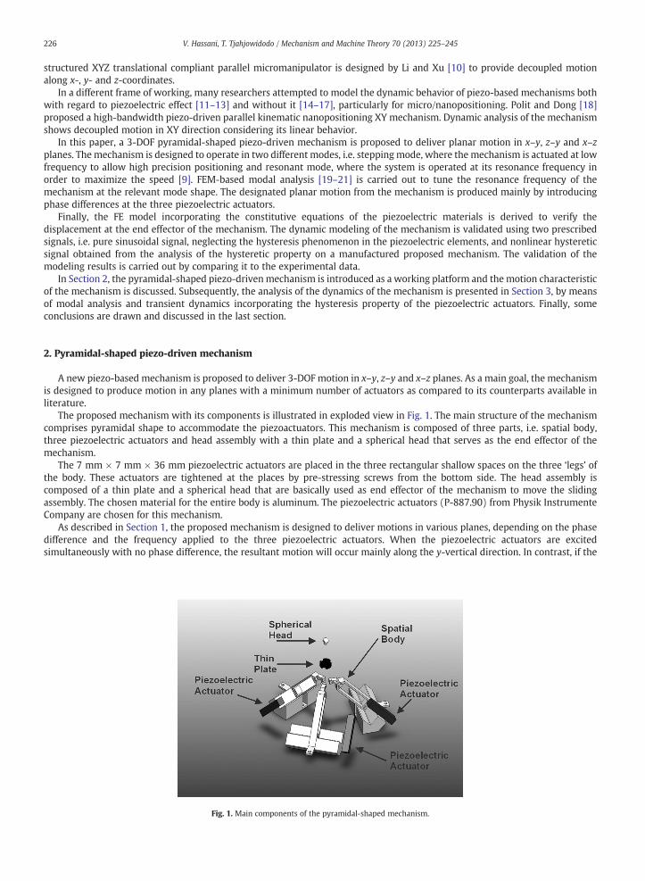
The proposed mechanism with its components is illustrated in exploded view in Fig. 1. The main structure of the mechanismcomprises pyramidal shape to accommodate the piezoactuators. This mechanism is composed of three parts, i.e. spatial body,three piezoelectric actuators and head assembly with a thin plate and a spherical head that serves as the end effector of themechanism.
The 7 mm × 7 mm × 36 mm piezoelectric actuators are placed in the three rectangular shallow spaces on the three ‘legs’ ofthe body. These actuators are tightened at the places by pre-stressing screws from the bottom side. The head assembly iscomposed of a thin plate and a spherical head that are basically used as end effector of the mechanism to move the slidingassembly. The chosen material for the entire body is aluminum. The piezoelectric actuators (P-887.90) from Physik InstrumenteCompany are chosen for this mechanism.
As described in Section 1, the proposed mechanism is designed to deliver motions in various planes, depending on the phasedifference and the frequency applied to the three piezoelectric actuators. When the piezoelectric actuators are excitedsimultaneously with no phase difference, the resultant motion will occur mainly along the y-vertical direction. In contrast, if the
Fig. 1. Main components of the pyramidal-shaped mechanism.
227V. Hassani, T. Tjahjowidodo / Mechanism and Machine Theory 70 (2013) 225–245
piezoelectric actuators are excited with a certain phase difference, a combination of motion in both horizontal and vertical planeswill occur.
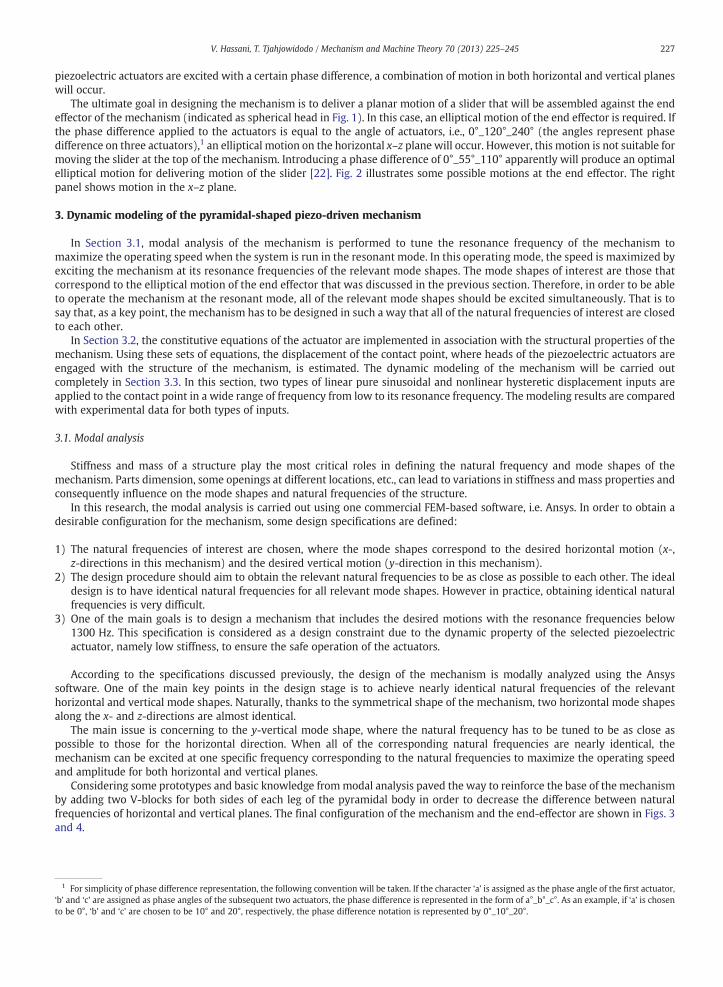
The ultimate goal in designing the mechanism is to deliver a planar motion of a slider that will be assembled against the endeffector of the mechanism (indicated as spherical head in Fig. 1). In this case, an elliptical motion of the end effector is required. Ifthe phase difference applied to the actuators is equal to the angle of actuators, i.e., 0°_120°_240° (the angles represent phasedifference on three actuators),1 an elliptical motion on the horizontal x–z plane will occur. However, this motion is not suitable formoving the slider at the top of the mechanism. Introducing a phase difference of 0°_55°_110° apparently will produce an optimalelliptical motion for delivering motion of the slider [22]. Fig. 2 illustrates some possible motions at the end effector. The rightpanel shows motion in the x–z plane.
3. Dynamic modeling of the pyramidal-shaped piezo-driven mechanism
In Section 3.1, modal analysis of the mechanism is performed to tune the resonance frequency of the mechanism tomaximize the operating speed when the system is run in the resonant mode. In this operating mode, the speed is maximized byexciting the mechanism at its resonance frequencies of the relevant mode shapes. The mode shapes of interest are those thatcorrespond to the elliptical motion of the end effector that was discussed in the previous section. Therefore, in order to be ableto operate the mechanism at the resonant mode, all of the relevant mode shapes should be excited simultaneously. That is tosay that, as a key point, the mechanism has to be designed in such a way that all of the natural frequencies of interest are closedto each other.
In Section 3.2, the constitutive equations of the actuator are implemented in association with the structural properties of themechanism. Using these sets of equations, the displacement of the contact point, where heads of the piezoelectric actuators areengaged with the structure of the mechanism, is estimated. The dynamic modeling of the mechanism will be carried outcompletely in Section 3.3. In this section, two types of linear pure sinusoidal and nonlinear hysteretic displacement inputs areapplied to the contact point in a wide range of frequency from low to its resonance frequency. The modeling results are comparedwith experimental data for both types of inputs.
3.1. Modal analysis
Stiffness and mass of a structure play the most critical roles in defining the natural frequency and mode shapes of themechanism. Parts dimension, some openings at different locations, etc., can lead to variations in stiffness and mass properties andconsequently influence on the mode shapes and natural frequencies of the structure.
In this research, the modal analysis is carried out using one commercial FEM-based software, i.e. Ansys. In order to obtain adesirable configuration for the mechanism, some design specifications are defined:
1) The natural frequencies of interest are chosen, where the mode shapes correspond to the desired horizontal motion (x-,z-directions in this mechanism) and the desired vertical motion (y-direction in this mechanism).
2) The design procedure should aim to obtain the relevant natural frequencies to be as close as possible to each other. The idealdesign is to have identical natural frequencies for all relevant mode shapes. However in practice, obtaining identical naturalfrequencies is very difficult.
3) One of the main goals is to design a mechanism that includes the desired motions with the resonance frequencies below1300 Hz. This specification is considered as a design constraint due to the dynamic property of the selected piezoelectricactuator, namely low stiffness, to ensure the safe operation of the actuators.
According to the specifications discussed previously, the design of the mechanism is modally analyzed using the Ansyssoftware. One of the main key points in the design stage is to achieve nearly identical natural frequencies of the relevanthorizontal and vertical mode shapes. Naturally, thanks to the symmetrical shape of the mechanism, two horizontal mode shapesalong the x- and z-directions are almost identical.
The main issue is concerning to the y-vertical mode shape, where the natural frequency has to be tuned to be as close aspossible to those for the horizontal direction. When all of the corresponding natural frequencies are nearly identical, themechanism can be excited at one specific frequency corresponding to the natural frequencies to maximize the operating speedand amplitude for both horizontal and vertical planes.
Considering some prototypes and basic knowledge frommodal analysis paved the way to reinforce the base of the mechanismby adding two V-blocks for both sides of each leg of the pyramidal body in order to decrease the difference between naturalfrequencies of horizontal and vertical planes. The final configuration of the mechanism and the end-effector are shown in Figs. 3and 4.
1 For simplicity of phase difference representation, the following convention will be taken. If the character ‘a’ is assigned as the phase angle of the first actuator,‘b’ and ‘c’ are assigned as phase angles of the subsequent two actuators, the phase difference is represented in the form of a°_b°_c°. As an example, if ‘a’ is chosento be 0°, ‘b’ and ‘c’ are chosen to be 10° and 20°, respectively, the phase difference notation is represented by 0°_10°_20°.
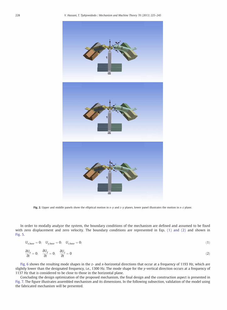
Fig. 2. Upper and middle panels show the elliptical motion in x–y and z–y planes, lower panel illustrates the motion in x–z plane.
228 V. Hassani, T. Tjahjowidodo / Mechanism and Machine Theory 70 (2013) 225–245
In order to modally analyze the system, the boundary conditions of the mechanism are defined and assumed to be fixedwith zero displacement and zero velocity. The boundary conditions are represented in Eqs. (1) and (2) and shown inFig. 5.
Ux;base ¼ 0; Uy;base ¼ 0; Uz;base ¼ 0; ð1Þ
∂Ux
∂t ¼ 0;∂Uy
∂t ¼ 0;∂Uz
∂t ¼ 0 ð2Þ
Fig. 6 shows the resulting mode shapes in the z- and x-horizontal directions that occur at a frequency of 1193 Hz, which areslightly lower than the designated frequency, i.e., 1300 Hz. The mode shape for the y-vertical direction occurs at a frequency of1137 Hz that is considered to be close to those in the horizontal plane.
Concluding the design optimization of the proposed mechanism, the final design and the construction aspect is presented inFig. 7. The figure illustrates assembled mechanism and its dimensions. In the following subsection, validation of the model usingthe fabricated mechanism will be presented.
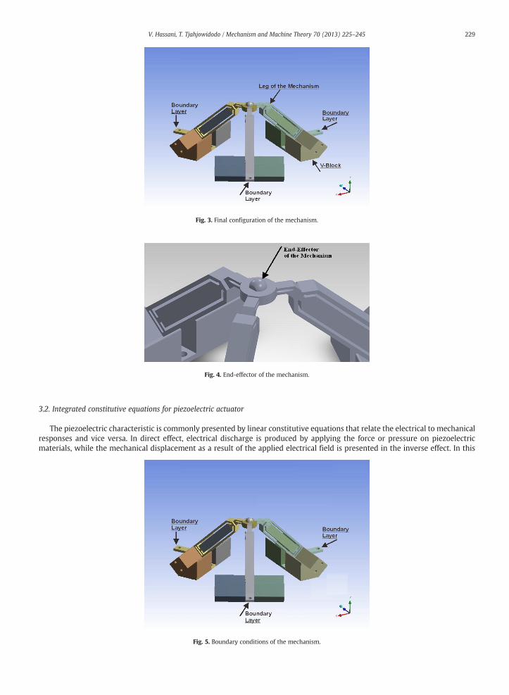
Fig. 4. End-effector of the mechanism.
Fig. 3. Final configuration of the mechanism.
229V. Hassani, T. Tjahjowidodo / Mechanism and Machine Theory 70 (2013) 225–245
3.2. Integrated constitutive equations for piezoelectric actuator
The piezoelectric characteristic is commonly presented by linear constitutive equations that relate the electrical to mechanicalresponses and vice versa. In direct effect, electrical discharge is produced by applying the force or pressure on piezoelectricmaterials, while the mechanical displacement as a result of the applied electrical field is presented in the inverse effect. In this
Fig. 5. Boundary conditions of the mechanism.
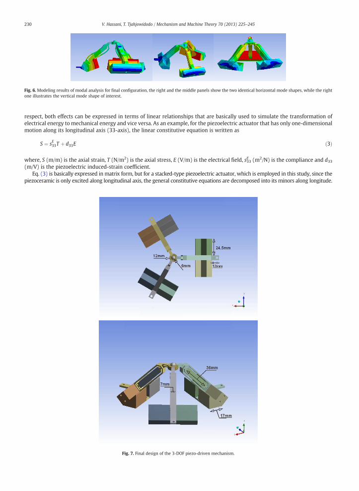
Fig. 6. Modeling results of modal analysis for final configuration, the right and the middle panels show the two identical horizontal mode shapes, while the rightone illustrates the vertical mode shape of interest.
230 V. Hassani, T. Tjahjowidodo / Mechanism and Machine Theory 70 (2013) 225–245
respect, both effects can be expressed in terms of linear relationships that are basically used to simulate the transformation ofelectrical energy to mechanical energy and vice versa. As an example, for the piezoelectric actuator that has only one-dimensionalmotion along its longitudinal axis (33-axis), the linear constitutive equation is written as
S ¼ sE33T þ d33E ð3Þ
, S (m/m) is the axial strain, T (N/m2) is the axial stress, E (V/m) is the electrical field, s33E (m2/N) is the compliance and d33
where(m/V) is the piezoelectric induced-strain coefficient.Eq. (3) is basically expressed in matrix form, but for a stacked-type piezoelectric actuator, which is employed in this study, since thepiezoceramic is only excited along longitudinal axis, the general constitutive equations are decomposed into its minors along longitude.
Fig. 7. Final design of the 3-DOF piezo-driven mechanism.
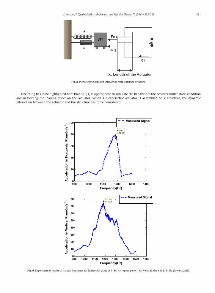
Fig. 8. Piezoelectric actuator interaction with external structure.
231V. Hassani, T. Tjahjowidodo / Mechanism and Machine Theory 70 (2013) 225–245
One thing has to be highlighted here that Eq. (3) is appropriate to simulate the behavior of the actuator under static conditionand neglecting the loading effect on the actuator. When a piezoelectric actuator is assembled on a structure, the dynamicinteraction between the actuator and the structure has to be considered.
900 1000 1100 1200 1300 14000
20
40
60
80
100
X: 1184Y: 77.08
Frequency(Hz)
Measured Signal
900 1000 1100 1200 1300 1400 1500 16000
10
20
30
40
50
60
70
80 X: 1184Y: 72.21
Frequency(Hz)
Acc
eler
atio
n in
Ver
tica
l Pla
ne(
m/s
2 )
Measured Signal
Acc
eler
atio
n in
Ho
rizo
nta
l Pla
ne(
m/s
2 )
Fig. 9. Experimental results of natural frequency for horizontal plane at 1184 Hz (upper panel); for vertical plane at 1184 Hz (lower panel).
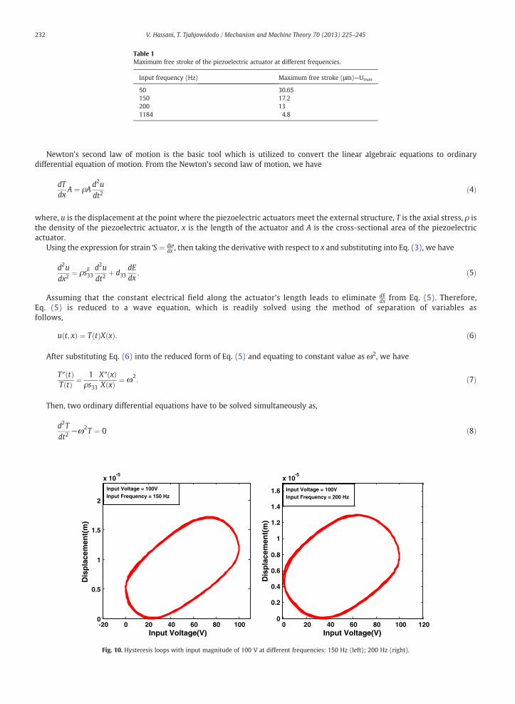
Table 1Maximum free stroke of the piezoelectric actuator at different frequencies.
Input frequency (Hz) Maximum free stroke (μm)—Umax
50 30.65150 17.2200 131184 4.8
232 V. Hassani, T. Tjahjowidodo / Mechanism and Machine Theory 70 (2013) 225–245
Newton's second law of motion is the basic tool which is utilized to convert the linear algebraic equations to ordinarydifferential equation of motion. From the Newton's second law of motion, we have
dTdx
A ¼ ρAd2udt2
ð4Þ
, u is the displacement at the point where the piezoelectric actuators meet the external structure, T is the axial stress, ρ is
wherethe density of the piezoelectric actuator, x is the length of the actuator and A is the cross-sectional area of the piezoelectricactuator.Using the expression for strain ‘S ¼ dudx’, then taking the derivative with respect to x and substituting into Eq. (3), we have
d2udx2
¼ ρsE33d2udt2
þ d33dEdx
: ð5Þ
Assuming that the constant electrical field along the actuator's length leads to eliminate dEdx from Eq. (5). Therefore,
Eq. (5) is reduced to a wave equation, which is readily solved using the method of separation of variables asfollows,
u t; xð Þ ¼ T tð ÞX xð Þ: ð6Þ
After substituting Eq. (6) into the reduced form of Eq. (5) and equating to constant value as ω2, we have
T″ tð ÞT tð Þ ¼ 1
ρs33
X″ xð ÞX xð Þ ¼ ω2
: ð7Þ
Then, two ordinary differential equations have to be solved simultaneously as,
d2Tdt2
−ω2T ¼ 0 ð8Þ
-20 0 20 40 60 80 1000
0.5
1
1.5
2
x 10-5
Input Voltage(V)
Dis
pla
cem
ent(
m)
Dis
pla
cem
ent(
m)
Input Voltage = 100VInput Frequency = 150 Hz
0 20 40 60 80 100 1200
0.2
0.4
0.6
0.8
1
1.2
1.4
1.6
x 10-5
Input Voltage(V)
Input Voltage = 100VInput Frequency = 200 Hz
Fig. 10. Hysteresis loops with input magnitude of 100 V at different frequencies: 150 Hz (left); 200 Hz (right).
where
a b
c d
0 0.01 0.02 0.03 0.040
0.5
1
1.5
2
2.5
3
x 10-5
Time(sec)
Dis
pla
cem
ent(
m)
Pure Sinusoidal InputHysteretic Input
0 0.002 0.004 0.006 0.008 0.01 0.0120
0.5
1
1.5
2x 10
-5
Time(sec)
Dis
pla
cem
ent(
m)
Pure Sinusoidal InputHysteretic Input
0 0.002 0.004 0.006 0.008 0.010
0.2
0.4
0.6
0.8
1
1.2
1.4
1.6x 10⁻⁵
Time(sec)
Dis
pla
cem
ent(
m)
Pure Sinusoidal InputHysteretic Input
0 0.5 1 1.5 2 2.5x 10
-3
0
0.5
1
1.5
2
2.5
x 10-6
Time(sec)
Dis
pla
cem
ent(
m)
Pure Sinusoidal InputHysteretic Input
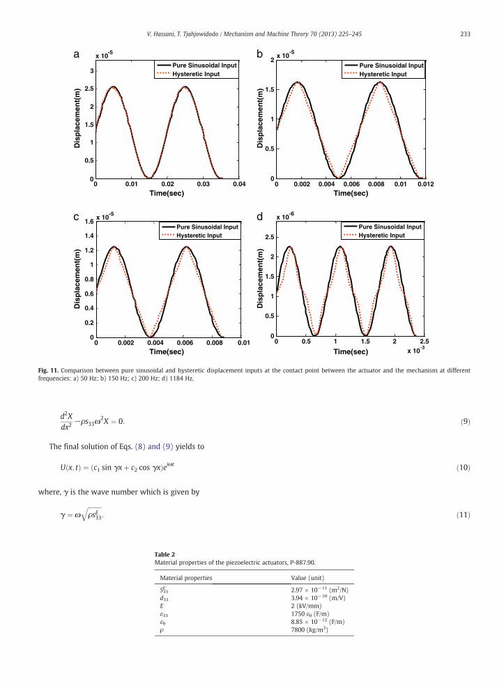
Fig. 11. Comparison between pure sinusoidal and hysteretic displacement inputs at the contact point between the actuator and the mechanism at differentfrequencies: a) 50 Hz; b) 150 Hz; c) 200 Hz; d) 1184 Hz.
233V. Hassani, T. Tjahjowidodo / Mechanism and Machine Theory 70 (2013) 225–245
d2Xdx2
−ρs33ω2X ¼ 0: ð9Þ
The final solution of Eqs. (8) and (9) yields to
U x; tð Þ ¼ c1 sin γxþ c2 cos γxð Þeiωt ð10Þ
, γ is the wave number which is given by
γ ¼ ωffiffiffiffiffiffiffiffiffiρsE33
q: ð11Þ
Table 2Material properties of the piezoelectric actuators, P-887.90.
Material properties Value (unit)
S33E 2.97 × 10⁻¹¹ (m2/N)d33 3.94 × 10⁻¹⁰ (m/V)E 2 (kV/mm)ε33 1750 ε0 (F/m)ε0 8.85 × 10⁻¹² (F/m)ρ 7800 (kg/m3)
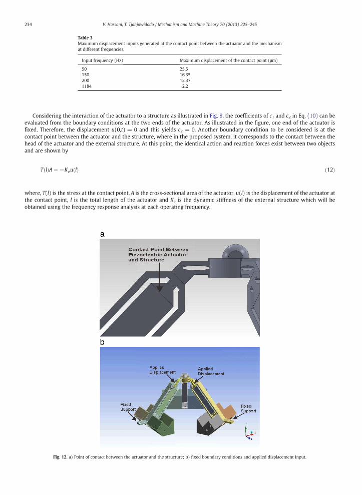
Table 3Maximum displacement inputs generated at the contact point between the actuator and the mechanismat different frequencies.
Input frequency (Hz) Maximum displacement of the contact point (μm)
50 25.5150 16.35200 12.371184 2.2
234 V. Hassani, T. Tjahjowidodo / Mechanism and Machine Theory 70 (2013) 225–245
Considering the interaction of the actuator to a structure as illustrated in Fig. 8, the coefficients of c1 and c2 in Eq. (10) can beevaluated from the boundary conditions at the two ends of the actuator. As illustrated in the figure, one end of the actuator isfixed. Therefore, the displacement u(0,t) = 0 and this yields c2 = 0. Another boundary condition to be considered is at thecontact point between the actuator and the structure, where in the proposed system, it corresponds to the contact between thehead of the actuator and the external structure. At this point, the identical action and reaction forces exist between two objectsand are shown by
T lð ÞA ¼ −Keu lð Þ ð12Þ
, T(l) is the stress at the contact point, A is the cross-sectional area of the actuator, u(l) is the displacement of the actuator at
wherethe contact point, l is the total length of the actuator and Ke is the dynamic stiffness of the external structure which will beobtained using the frequency response analysis at each operating frequency.Fig. 12. a) Point of contact between the actuator and the structure; b) fixed boundary conditions and applied displacement input.
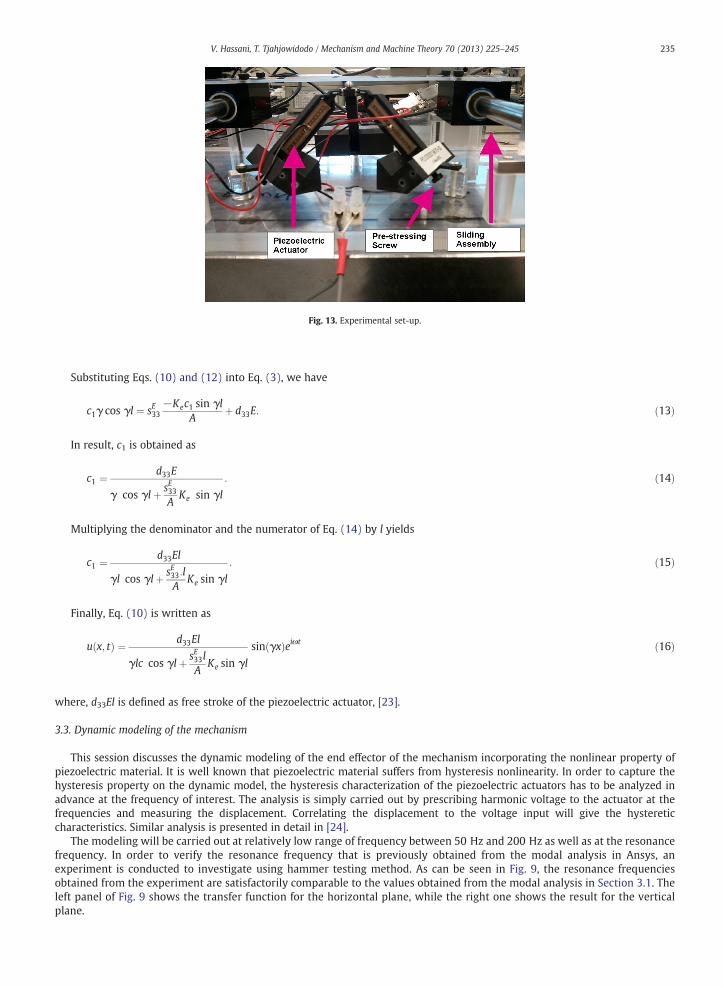
Fig. 13. Experimental set-up.
235V. Hassani, T. Tjahjowidodo / Mechanism and Machine Theory 70 (2013) 225–245
Substituting Eqs. (10) and (12) into Eq. (3), we have
where
c1γ cos γl ¼ sE33−Kec1 sin γl
Aþ d33E: ð13Þ
In result, c1 is obtained as
c1 ¼ d33E
γ cos γlþ sE33A
Ke sin γl
: ð14Þ
Multiplying the denominator and the numerator of Eq. (14) by l yields
c1 ¼ d33El
γl cos γlþ sE33:lA
Ke sin γl
: ð15Þ
Finally, Eq. (10) is written as
u x; tð Þ ¼ d33El
γlc cos γlþ sE33lA
Ke sin γl
sin γxð Þeiωt ð16Þ
, d33El is defined as free stroke of the piezoelectric actuator, [23].
3.3. Dynamic modeling of the mechanism
This session discusses the dynamic modeling of the end effector of the mechanism incorporating the nonlinear property ofpiezoelectric material. It is well known that piezoelectric material suffers from hysteresis nonlinearity. In order to capture thehysteresis property on the dynamic model, the hysteresis characterization of the piezoelectric actuators has to be analyzed inadvance at the frequency of interest. The analysis is simply carried out by prescribing harmonic voltage to the actuator at thefrequencies and measuring the displacement. Correlating the displacement to the voltage input will give the hystereticcharacteristics. Similar analysis is presented in detail in [24].
The modeling will be carried out at relatively low range of frequency between 50 Hz and 200 Hz as well as at the resonancefrequency. In order to verify the resonance frequency that is previously obtained from the modal analysis in Ansys, anexperiment is conducted to investigate using hammer testing method. As can be seen in Fig. 9, the resonance frequenciesobtained from the experiment are satisfactorily comparable to the values obtained from the modal analysis in Section 3.1. Theleft panel of Fig. 9 shows the transfer function for the horizontal plane, while the right one shows the result for the verticalplane.
236 V. Hassani, T. Tjahjowidodo / Mechanism and Machine Theory 70 (2013) 225–245
Having the resonance frequency at 1184 Hz for both the horizontal and vertical mode shapes, the maximum free stroke of theactuator is subsequently measured at this frequency in addition to a few low frequencies of interest. The free stroke is measuredon the actuators directly. Table 1 shows the maximum stroke of the actuator at different frequencies ranging from low to theresonance frequency.
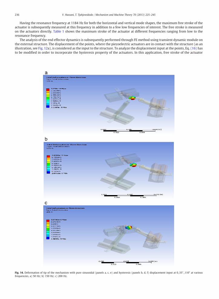
The analysis of the end effector dynamics is subsequently performed through FE method using transient dynamic module onthe external structure. The displacement of the points, where the piezoelectric actuators are in contact with the structure (as anillustration, see Fig. 12a), is considered as the input to the structure. To analyze the displacement input at the points, Eq. (16) hasto be modified in order to incorporate the hysteresis property of the actuators. In this application, free stroke of the actuator
Fig. 14. Deformation of tip of the mechanism with pure sinusoidal (panels a, c, e) and hysteresis (panels b, d, f) displacement input at 0_55°_110° at variousfrequencies, a) 50 Hz; b) 150 Hz; c) 200 Hz.
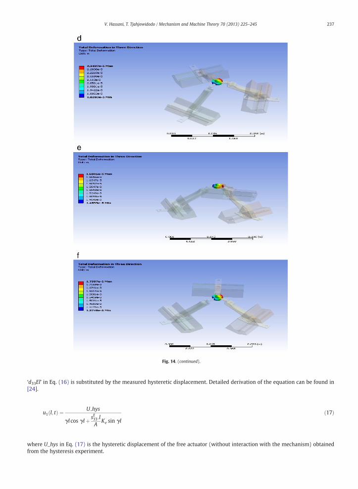
Fig. 14. (continued).
237V. Hassani, T. Tjahjowidodo / Mechanism and Machine Theory 70 (2013) 225–245
‘d33El’ in Eq. (16) is substituted by the measured hysteretic displacement. Detailed derivation of the equation can be found in[24].
u1 l; tð Þ ¼ U hys
γl cos γlþ sE33:lA
Ke sin γl
ð17Þ
U_hys in Eq. (17) is the hysteretic displacement of the free actuator (without interaction with the mechanism) obtained
wherefrom the hysteresis experiment.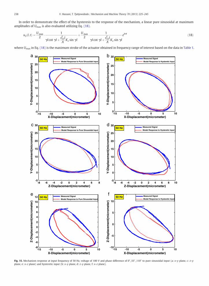
238 V. Hassani, T. Tjahjowidodo / Mechanism and Machine Theory 70 (2013) 225–245
In order to demonstrate the effect of the hysteresis to the response of the mechanism, a linear pure sinusoidal at maximumamplitudes of Umax is also evaluated utilizing Eq. (18).
where
Fig. 15.plane, e
u2 l; tð Þ ¼ Umax
2� 1
γl cot γlþ sE33lA
Ke sin γl
þ Umax
2� 1
γl cot γlþ sE33lA
Ke sin γl
eiωt ð18Þ
Umax in Eq. (18) is the maximum stroke of the actuator obtained in frequency range of interest based on the data in Table 1.
a b
c d
e f
-15 -10 -5 0 5 10-5
0
5
10
15
20
25
30
X-Displacement(micrometer)
Y-D
isp
lace
men
t(m
icro
met
er)
Y-D
isp
lace
men
t(m
icro
met
er)
Measured Signal
Model Response to Pure Sinusoidal input50 Hz
-15 -10 -5 0 5 100
5
10
15
20
25
30
X-Displacement(micrometer)
Measured Signal
Model Response to Hysteretic Input50 Hz
-8 -6 -4 -2 0 2 4 6 8-5
0
5
10
15
20
25
30
Z-Displacement(micrometer)
Measured Signal
Model Response to Pure Sinusoidal Input50 Hz
-8 -6 -4 -2 0 2 4 6 8 10-5
0
5
10
15
20
25
30
Z-Displacement(micrometer)
Measured Signal
Model Response to Hysteretic Input50 Hz
-15 -10 -5 0 5 10-8
-6
-4
-2
0
2
4
6
8
10
12
X-Displacement(micrometer)
Z-D
isp
lace
men
t(m
icro
met
er)
Y-D
isp
lace
men
t(m
icro
met
er)
Y-D
isp
lace
men
t(m
icro
met
er)
Z-D
isp
lace
men
t(m
icro
met
er)
Measured Signal
Model Response to Pure Sinusoidal Input50 Hz
-15 -10 -5 0 5 10-10
-5
0
5
10
X-Displacement(micrometer)
Measured Signal
Model Response to Hysteretic Input50 Hz
Mechanism response at input frequency of 50 Hz, voltage of 100 V and phase difference of 0°_55°_110° to pure sinusoidal input (a: x–y plane, c: z–y: x–z plane) and hysteretic input (b: x–y plane, d: z–y plane, f: x–z plane).
a b
c d
e f
-6 -4 -2 0 2 4 60
2
4
6
8
10
12
14
16
18
20
X-Displacement(micrometer)
Measured SignalModel Response to Pure Sinusoidal Input
150 Hz
-6 -4 -2 0 2 4 60
2
4
6
8
10
12
14
16
18
X-Displacement(micrometer)
Measured Signal
Model Response to Hysteretic Input150 Hz
-3 -2 -1 0 1 2 3 4-2
0
2
4
6
8
10
12
14
16
18
Z-Displacement(micrometer)
Y-D
isp
lace
men
t(m
icro
met
er)
Y-D
isp
lace
men
t(m
icro
met
er)
Measured Signal
Model Response to Pure Sinusoidal Input150 Hz
-3 -2 -1 0 1 2 3 40
2
4
6
8
10
12
14
16
18
Z-Displacement(micrometer)
Y-D
isp
lace
men
t(m
icro
met
er)
Y-D
isp
lace
men
t(m
icro
met
er)
Measured Signal
Model Response to Hysteretic Input150 Hz
-6 -4 -2 0 2 4 6
-2
0
2
4
6
8
X-Displacement(micrometer)
Z-D
isp
lace
men
t(m
icro
met
er)
Measured Signal
Model Response to Pure Sinusoidal Input150 Hz
-6 -4 -2 0 2 4 6
-2
0
2
4
6
8
X-Displacement(micrometer)
Z-D
isp
lace
men
t(m
icro
met
er)
Measured Signal
Model Response to Hysteretic Input150 Hz
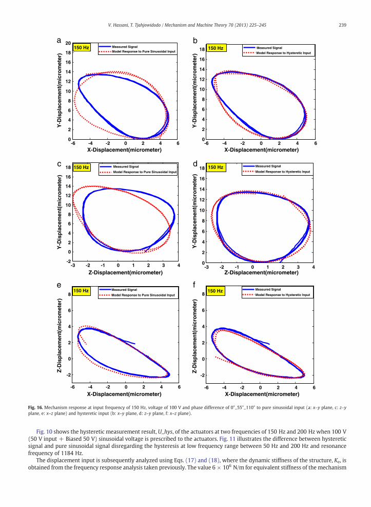
Fig. 16. Mechanism response at input frequency of 150 Hz, voltage of 100 V and phase difference of 0°_55°_110° to pure sinusoidal input (a: x–y plane, c: z–yplane, e: x–z plane) and hysteretic input (b: x–y plane, d: z–y plane, f: x–z plane).
239V. Hassani, T. Tjahjowidodo / Mechanism and Machine Theory 70 (2013) 225–245
Fig. 10 shows the hysteretic measurement result, U_hys, of the actuators at two frequencies of 150 Hz and 200 Hz when 100 V(50 V input + Biased 50 V) sinusoidal voltage is prescribed to the actuators. Fig. 11 illustrates the difference between hystereticsignal and pure sinusoidal signal disregarding the hysteresis at low frequency range between 50 Hz and 200 Hz and resonancefrequency of 1184 Hz.
The displacement input is subsequently analyzed using Eqs. (17) and (18), where the dynamic stiffness of the structure, Ke, isobtained from the frequency response analysis taken previously. The value 6 × 10⁶ N/m for equivalent stiffness of the mechanism
240 V. Hassani, T. Tjahjowidodo / Mechanism and Machine Theory 70 (2013) 225–245
at low frequency range of interest i.e. between 50 Hz and 200 Hz is obtained from the transfer function as shown in Fig. 9,while this value is reduced to 5 × 10⁶ N/m at the resonance frequency. Table 2 displays the material properties of thepiezoelectric actuator and Table 3 displays maximum displacement generated by the actuator at the contact point at differentfrequencies.
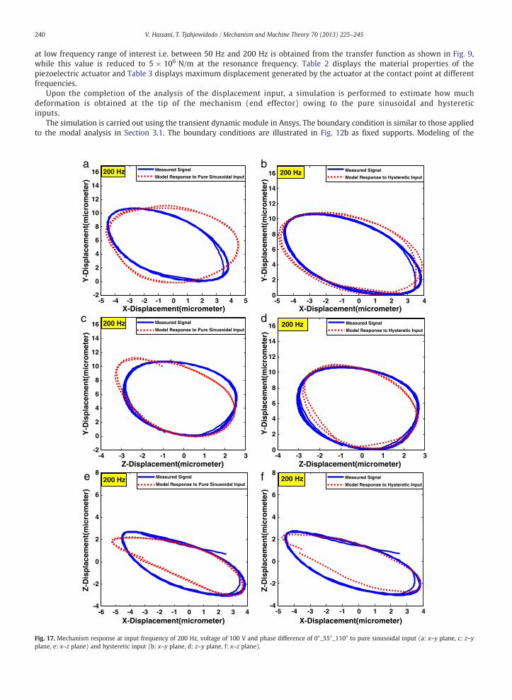
Upon the completion of the analysis of the displacement input, a simulation is performed to estimate how muchdeformation is obtained at the tip of the mechanism (end effector) owing to the pure sinusoidal and hystereticinputs.
The simulation is carried out using the transient dynamic module in Ansys. The boundary condition is similar to those appliedto the modal analysis in Section 3.1. The boundary conditions are illustrated in Fig. 12b as fixed supports. Modeling of the
a b
c d
e f
-5 -4 -3 -2 -1 0 1 2 3 4 5-2
0
2
4
6
8
10
12
14
16
X-Displacement(micrometer)
Measured Signal
Model Response to Pure Sinusoidal Input200 Hz
-5 -4 -3 -2 -1 0 1 2 3 40
2
4
6
8
10
12
14
16
X-Displacement(micrometer)
Measured Signal
Model Response to Hysteretic Input200 Hz
-4 -3 -2 -1 0 1 2 3-2
0
2
4
6
8
10
12
14
16
Z-Displacement(micrometer)
Y-D
isp
lace
men
t(m
icro
met
er)
Measured Signal
Model Response to Pure Sinusoidal Input200 Hz
-4 -3 -2 -1 0 1 2 30
2
4
6
8
10
12
14
16
Z-Displacement(micrometer)
Measured Signal
Model Response to Hysteretic Input200 Hz
-6 -5 -4 -3 -2 -1 0 1 2 3 4-4
-2
0
2
4
6
8
X-Displacement(micrometer)
Measured Signal
Model Response to Pure Sinusoidal Input200 Hz
-5 -4 -3 -2 -1 0 1 2 3 4-4
-2
0
2
4
6
8
X-Displacement(micrometer)
Measured Signal
Model Response to Hysteretic Input200 Hz
Y-D
isp
lace
men
t(m
icro
met
er)
Y-D
isp
lace
men
t(m
icro
met
er)
Y-D
isp
lace
men
t(m
icro
met
er)
Z-D
isp
lace
men
t(m
icro
met
er)
Z-D
isp
lace
men
t(m
icro
met
er)
Fig. 17. Mechanism response at input frequency of 200 Hz, voltage of 100 V and phase difference of 0°_55°_110° to pure sinusoidal input (a: x–y plane, c: z–yplane, e: x–z plane) and hysteretic input (b: x–y plane, d: z–y plane, f: x–z plane).
a b
c d
e f
-15 -10 -5 0 5 10-15
-10
-5
0
5
10
15
20
X-Displacement(micrometer)
Measured Signal
Model Response to Pure Sinusoidal Input50 Hz
-15 -10 -5 0 5 10-15
-10
-5
0
5
10
15
20
X-Displacement(micometer)
Measured Signal
Model Response to Hysteretic Input50 Hz
-6 -4 -2 0 2 4 6 8
-5
0
5
10
15
X-Displacement(micrometer)
Measured Signal
Model Response to Pure Sinusoidal Input150 Hz
-6 -4 -2 0 2 4 6 8-8
-6
-4
-2
0
2
4
6
8
10
12
X-Displacement(micrometer)
Measured Signal
Model Response to Hysteretic Input150 Hz
-5 -4 -3 -2 -1 0 1 2 3 4 5-6
-4
-2
0
2
4
6
8
10
X-Displacement(micrometer)
Measured Signal
Model Response to Pure Sinusoidal Input200 Hz
-5 -4 -3 -2 -1 0 1 2 3 4 5-6
-4
-2
0
2
4
6
8
10
12
X-Displacement(micrometer)
Z-D
isp
lace
men
t(m
ico
rmet
er)
Measured Signal
Model Response to Hysteretic Input200 Hz
Y-D
isp
lace
men
t(m
icro
met
er)
Z-D
isp
lace
men
t(m
icro
met
er)
Z-D
isp
lace
men
t(m
icro
met
er)
Z-D
isp
lace
men
t(m
icro
met
er)
Z-D
isp
lace
men
t(m
icro
met
er)
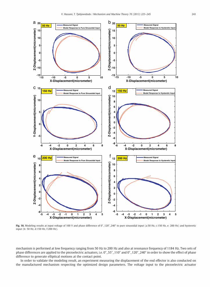
Fig. 18. Modeling results at input voltage of 100 V and phase difference of 0°_120°_240° to pure sinusoidal input (a:50 Hz, c:150 Hz, e: 200 Hz) and hystereticinput (b: 50 Hz, d:150 Hz, f:200 Hz).
241V. Hassani, T. Tjahjowidodo / Mechanism and Machine Theory 70 (2013) 225–245
mechanism is performed at low frequency ranging from 50 Hz to 200 Hz and also at resonance frequency of 1184 Hz. Two sets ofphase differences are applied to the piezoelectric actuators, i.e. 0°_55°_110° and 0°_120°_240° in order to show the effect of phasedifference to generate elliptical motions at the contact point.
In order to validate the modeling result, an experiment measuring the displacement of the end effector is also conducted onthe manufactured mechanism respecting the optimized design parameters. The voltage input to the piezoelectric actuator
a b
c d
e f
-3 -2 -1 0 1 2 3 4
0
0.5
1
1.5
2
X-Displacement(micrometer)
Y-D
isp
lace
men
t(m
icro
met
er)
Measured Signal
Model Response to Pure Sinusoidal Input1184 Hz
-3 -2 -1 0 1 2 3 4
0
0.5
1
1.5
2
X-Displacement(micrometer)
Y-D
isp
lace
men
t(m
icro
met
er)
Measured Signal
Model Response to Hysteretic Input1184 Hz
-1.5 -1 -0.5 0 0.5 1
0
0.5
1
1.5
2
Z-Displacement(micrometer)
Y-D
isp
lace
men
t(m
icro
met
r)
Measured Signal
Model Response to Pure Sinusoidal Input1184 Hz
-1 -0.8 -0.6 -0.4 -0.2 0 0.2 0.4 0.6 0.8
0
0.5
1
1.5
2
Z-Displacement(micrometer)
Y-D
isp
lace
men
t(m
icro
met
er)
Measured Signal
Model Response to Hysteretic Input1184 Hz
-3 -2 -1 0 1 2 3 4-1
-0.5
0
0.5
1
1.5
2
X-Displacement(micrometer)
Z-D
isp
lace
men
t(m
icro
met
er)
Measured Signal
Model Response to Pure Sinusoidal Input1184 Hz
-3 -2 -1 0 1 2 3 4-1
-0.5
0
0.5
1
1.5
2
X-Displacement(micrometer)
Z-D
isp
lace
men
t(m
icro
met
er)
Measured Signal
Model Response to Hysteretic Input1184 Hz
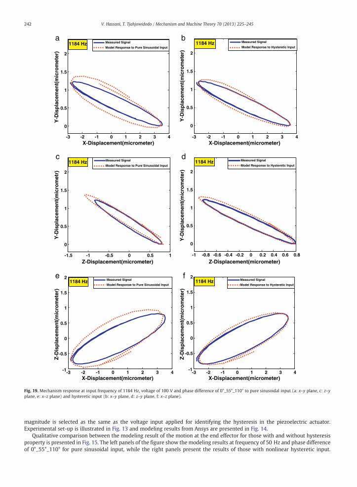
Fig. 19. Mechanism response at input frequency of 1184 Hz, voltage of 100 V and phase difference of 0°_55°_110° to pure sinusoidal input (a: x–y plane, c: z–yplane, e: x–z plane) and hysteretic input (b: x–y plane, d: z–y plane, f: x–z plane).
242 V. Hassani, T. Tjahjowidodo / Mechanism and Machine Theory 70 (2013) 225–245
magnitude is selected as the same as the voltage input applied for identifying the hysteresis in the piezoelectric actuator.Experimental set-up is illustrated in Fig. 13 and modeling results from Ansys are presented in Fig. 14.
Qualitative comparison between the modeling result of the motion at the end effector for those with and without hysteresisproperty is presented in Fig. 15. The left panels of the figure show the modeling results at frequency of 50 Hz and phase differenceof 0°_55°_110° for pure sinusoidal input, while the right panels present the results of those with nonlinear hysteretic input.
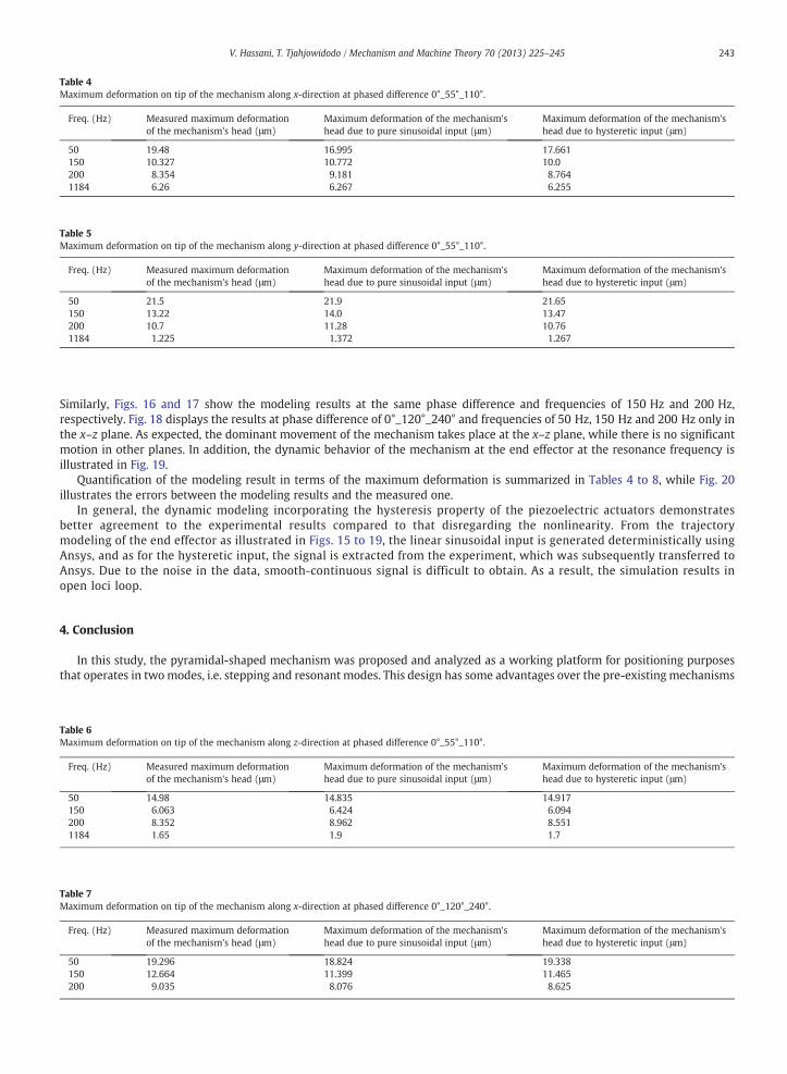
Table 4Maximum deformation on tip of the mechanism along x-direction at phased difference 0°_55°_110°.
Freq. (Hz) Measured maximum deformationof the mechanism's head (μm)
Maximum deformation of the mechanism'shead due to pure sinusoidal input (μm)
Maximum deformation of the mechanism'shead due to hysteretic input (μm)
50 19.48 16.995 17.661150 10.327 10.772 10.0200 8.354 9.181 8.7641184 6.26 6.267 6.255
Table 5Maximum deformation on tip of the mechanism along y-direction at phased difference 0°_55°_110°.
Freq. (Hz) Measured maximum deformationof the mechanism's head (μm)
Maximum deformation of the mechanism'shead due to pure sinusoidal input (μm)
Maximum deformation of the mechanism'shead due to hysteretic input (μm)
50 21.5 21.9 21.65150 13.22 14.0 13.47200 10.7 11.28 10.761184 1.225 1.372 1.267
243V. Hassani, T. Tjahjowidodo / Mechanism and Machine Theory 70 (2013) 225–245
Similarly, Figs. 16 and 17 show the modeling results at the same phase difference and frequencies of 150 Hz and 200 Hz,respectively. Fig. 18 displays the results at phase difference of 0°_120°_240° and frequencies of 50 Hz, 150 Hz and 200 Hz only inthe x–z plane. As expected, the dominant movement of the mechanism takes place at the x–z plane, while there is no significantmotion in other planes. In addition, the dynamic behavior of the mechanism at the end effector at the resonance frequency isillustrated in Fig. 19.
Quantification of the modeling result in terms of the maximum deformation is summarized in Tables 4 to 8, while Fig. 20illustrates the errors between the modeling results and the measured one.
In general, the dynamic modeling incorporating the hysteresis property of the piezoelectric actuators demonstratesbetter agreement to the experimental results compared to that disregarding the nonlinearity. From the trajectorymodeling of the end effector as illustrated in Figs. 15 to 19, the linear sinusoidal input is generated deterministically usingAnsys, and as for the hysteretic input, the signal is extracted from the experiment, which was subsequently transferred toAnsys. Due to the noise in the data, smooth-continuous signal is difficult to obtain. As a result, the simulation results inopen loci loop.
4. Conclusion
In this study, the pyramidal-shaped mechanism was proposed and analyzed as a working platform for positioning purposesthat operates in twomodes, i.e. stepping and resonant modes. This design has some advantages over the pre-existing mechanisms
Table 6Maximum deformation on tip of the mechanism along z-direction at phased difference 0°_55°_110°.
Freq. (Hz) Measured maximum deformationof the mechanism's head (μm)
Maximum deformation of the mechanism'shead due to pure sinusoidal input (μm)
Maximum deformation of the mechanism'shead due to hysteretic input (μm)
50 14.98 14.835 14.917150 6.063 6.424 6.094200 8.352 8.962 8.5511184 1.65 1.9 1.7
Table 7Maximum deformation on tip of the mechanism along x-direction at phased difference 0°_120°_240°.
Freq. (Hz) Measured maximum deformationof the mechanism's head (μm)
Maximum deformation of the mechanism'shead due to pure sinusoidal input (μm)
Maximum deformation of the mechanism'shead due to hysteretic input (μm)
50 19.296 18.824 19.338150 12.664 11.399 11.465200 9.035 8.076 8.625
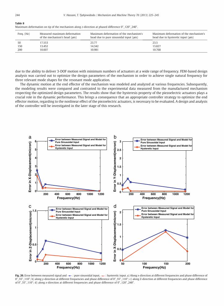
Table 8Maximum deformation on tip of the mechanism along z-direction at phased difference 0°_120°_240°.
Freq. (Hz) Measured maximum deformationof the mechanism's head (μm)
Maximum deformation of the mechanism'shead due to pure sinusoidal input (μm)
Maximum deformation of the mechanism'shead due to hysteretic input (μm)
50 17.553 23.77 23.5150 13.452 14.342 13.827200 10.607 10.981 10.768
244 V. Hassani, T. Tjahjowidodo / Mechanism and Machine Theory 70 (2013) 225–245
due to the ability to deliver 3-DOF motion with minimum numbers of actuators at a wide range of frequency. FEM-based designanalysis was carried out to optimize the design parameters of the mechanism in order to achieve single natural frequency forthree relevant mode shapes for the resonant mode application.
The dynamic motion at the end effector of the mechanism was modeled and analyzed at various frequencies. Subsequently,the modeling results were compared and contrasted to the experimental data measured from the manufactured mechanismrespecting the optimized design parameters. The results show that the hysteresis property of the piezoelectric actuators plays acrucial role in the dynamic performance. This brings a consequence that an appropriate controller strategy to optimize the endeffector motion, regarding to the nonlinear effect of the piezoelectric actuators, is necessary to be evaluated. A design and analysisof the controller will be investigated in the later stage of this research.
a b
200 400 600 800 1000 12000
1
2
3
4
5
6
Frequency(Hz)
Err
or
in X
-Dis
pla
cem
ent(
mic
ron
)
Error between Measured Signal and Model forPure Sinusoidal InputError between Measured Signal and Model forHysteretic Input
200 400 600 800 1000 12000
0.5
1
1.5
2
2.5
3
Frequency(Hz)
Err
or
in Y
-Dis
pla
cem
ent(
mic
ron
) Error between Measured Signal and Model forPure Sinusoidal InputError between Measured Signal and Model forHysteretic Input
c d
200 400 600 800 1000 12000
0.5
1
1.5
Frequency(Hz)
Err
or
in Z
-Dis
pla
cem
ent(
mic
ron
)
Error between Measured Signal and Model forPure Sinusoidal InputError between Measured Signal and Model forHysteretic Input
50 100 150 2000
0.5
1
1.5
2
Frequency(Hz)
Err
or
in X
-Dis
pla
cem
ent(
mic
ron
)
Error between Measured Signal and Model forPure Sinusoidal InputError between Measured Signal and Model forHysteretic Input
Fig. 20. Error between measured signal and : pure sinusoidal input, : hysteretic input. a) Along x-direction at different frequencies and phase difference of0°_55°_110°; b) along y-direction at different frequencies and phase difference of 0°_55°_110°; c) along Z-direction at different frequencies and phase differenceof 0°_55°_110°; d) along x-direction at different frequencies and phase difference of 0°_120°_240°.
245V. Hassani, T. Tjahjowidodo / Mechanism and Machine Theory 70 (2013) 225–245
References
[1] B.J. Kenton, K.K. Leang, Design and control of a three-axis serial-kinematic high-bandwidth nanopositioner, IEEE/ASME Transactions on Mechatronics 17(2012) 356–369.
[2] H. Van Brussel, D. Reynaerts, R. Vanherck, M. Versteyhe, S. Devos, A nanometre-precision, ultra-stiff piezostepper stage for ELID-grinding, CIRP Annals -Manufacturing Technology 52 (2003) 317–322.
[3] Y. Oner, E. Cetin, H.K. Ozturk, A. Yilanci, Design of a new three-degree of freedom spherical motor for photovoltaic-tracking systems, Journal of RenewableEnergy 34 (2009) 2751–2756.
[4] J. Zheng, A. Salton, M. Fu, A novel rotary dual-stage actuator positioner, 48th IEEE Conference on Decision and, Control, 2009, pp. 5426–5431.[5] G. Rogers, Three degree-of-freedom piezoelectric ultrasonic micro-motor with a major diameter of 350 μm, Journal of Micromechanics and
Microengineering 20 (2010) 1–5.[6] J.C. Zheng, M.Y. Fu, Y.Y. Wang, C.L. Du, Nonlinear tracking control for a hard disk drive dual-stage actuator system, IEEE/ASME Transactions on Mechatronics
13 (2007) 510–518.[7] Y. Ting, Y.D. Lee, Y.R. Tsai, C.Y. Chen, Stator design of a 2-DOF traveling-wave rotary piezoelectric motor, International Conference on Robotics and
Biomimetics, 2009, pp. 493–498.[8] E. Shamoto, T. Moriwaki, Rigid XYθ table for ultraprecision machine tool driven by means of walking drive, CIRP Annals - Manufacturing Technology 46
(1997) 301–304.[9] S. Devos, W. Van de Vijver, D. Mesonero-Romanos Vivanco, D. Reynaerts, H. Van Brussel, Piezoelectric motors with a stepping and a resonant operation
mode, Proceedings 9th International Conference on New Actuators, 2004, pp. 439–442.[10] Y.M. Li, Q.S. Xu, Design and optimization of an XYZ parallel micromanipulator with flexure hinges, Journal of Intelligent and Robotic Systems 55 (2009)
377–402.[11] M. Arafa, O. Aldraihem, A. Baz, Modeling and characterization of a linear piezomotor, Journal of Intelligent Material Systems and Structures 20 (2009)
1913–1921.[12] P.A. Juang, C.L. Lin, The electro-mechanical transfer function of an ultrasonic wheel system, Measurement: Journal of the International Measurement
Confederation 42 (2009) 1417–1425.[13] R. Merry, R. Van De Molengraft, M. Steinbuch, Modeling of a walking piezo actuator, IEEE International Conference on Control and Automation, 2009,
pp. 842–847.[14] M. Ishikawa, Y. Kinouchi, Modeling and control of spherical ultrasonic motor based on nonholonomic mechanics, International Conference on Intelligent
Robots and Systems, 2008, pp. 125–130.[15] S.L. Sharp, J.S.N. Paine, J.D. Blotter, Design of a linear ultrasonic piezoelectric motor, Journal of Intelligent Material Systems and Structures 21 (2010)
961–973.[16] Y. Tian, B. Shirinzadeh, D. Zhang, A flexure-based five-bar mechanism for micro/nano manipulation, Sensors and Actuators A: Physical 153 (2009) 96–104.[17] L. Xu, J. Xing, An inertial piezoelectric rotary motor, Proceedings of the Institution of Mechanical Engineers, Part C: Journal of Mechanical Engineering Science
224 (2010) 1165–1171.[18] S. Polit, J.Y. Dong, Development of a high-bandwidth XY nanopositioning stage for high-rate micro-/nanomanufacturing, IEEE/ASME Transactions on
Mechatronics 16 (2011) 724–733.[19] Y. Shi, Y. Li, C. Zhao, J. Zhang, A new type butterfly-shaped transducer linear ultrasonic motor, Journal of Intelligent Material Systems and Structures 22
(2011) 567–575.[20] N. Vittayaphadung, P. Smithmaitrie, Validation of the finite element model and vibration characteristic of the piezoelectric head gimbal assembly,
Proceedings of 12th International Conference on Computer Modelling and Simulation, 2010, pp. 375–379.[21] Y. Wang, J. Jin, W. Huang, A compact ultrasonic motor using two in plane modes, Symposium on Piezoelectricity, Acoustic Waves and Device Applications,
2010, pp. 171–174.[22] S. Ueha, Y. Tomikawa, M. Kurosawa, N. Nakamura, Ultrasonic Motors, Theory and Applications, Clarendon Press Oxford, 1993.[23] S.E. Lyshevski, Micromechatronics: Modeling, Analysis, and Design with MATLAB, CRC Press, 2003.[24] V. Hassani, T. Tjahjowidodo, Structural response investigation of a triangular-based piezoelectric drive mechanism to hysteresis effect of the piezoelectric
actuator, Journal of Mechanical Systems and Signal Processing 36 (1) (2013) 210–223.