Embed Size (px)
Citation preview

Journal of Engineering and Technology of The Open University of Sri Lanka (JET-OUSL), Vol. 1, No.1
35
Design of a Flight Control System in Compliance with Fling and Handling Quality Requirements
M. Ruwan Thilina Perera
Department of Mechanical Engineering, The Open University of Sri Lanka, Nawala,
Nugegoda, Sri Lanka.
Email: [email protected] Tele: +94112881477 ________________________________________________________________ Abstract- This paper presents the design of a flight control system (FCS) that offers the Aerosonde Unmanned Vehicle (UAV) with stability and control characteristics and capabilities of a classical aerial piloted aircraft. The design problem was formulated with a narrow focus on the following aspects of the UAV. The un-augmented open loop 6-DOF Aerosonde exhibits poor stability and control characteristics in compliance with MIL-F8785C flying quality standards. As in most classical fixed wing aircrafts, the control inputs to Aerosonde result in pitch, roll and yaw rate responses (rate command characteristics). This has made manual trimming of the UAV, at a given flight condition, with a human pilot-operator closing the loop, a daunting task. In the first phase of the design, a stability augmentation system was developed to improve the stability and control characteristics of the UAV compliance with MIL-F8785C flying qualities standard. In the second phase, a Rate-Command-Attitude-Hold system has been implemented to the FCS for longitudinal control of the UAV. In the third phase, an Auto-Stabilizer was deigned to control the Lateral-Directional command-response characteristics of the UAV. Both the Longitudinal and Lateral-Directional FCSs have been tested and simulated using linear and non-linear flight dynamic models of the UAV. Keywords: UAV, Flight Control, Stability and Control, Flying Qualities ______________________________________________________________________
Nomenclature A – State matrix B – Input matrix p – Roll rate (deg/s) q – Pitch rate (deg/s) r – Yaw rate (deg/s) u – Axial velocity (m/s), Input vector v – Lateral velocity (m/s) w – Normal velocity (m/s) h – Altitude (m) y – Output vector x – State vector Ku – Axial velocity gain constant Kw – Normal velocity gain constant Kθ – Pitch angle gain constant Kq – Axial velocity gain constant Kεq – Pitch rate integral gain const Kr – Yaw rate gain constant Kp – Roll rate gain constant Kari – Aileron-rudder interlink gain K – Gain vector qd – Pitch rate demand (deg/s) J – Performance index Tw – Washout filter time constant (s) Greek Letters
Journal of Engineering and Technology of The Open University of Sri Lanka (JET-OUSL), Vol. 1, No.1
36
ϕ – Roll angle (deg) θ – Pitch angle (deg) ψ – Yaw angle (deg) η – Elevator angle (deg) ζ – Rudder angle (deg) ξ – Aileron angle (deg) τ – Engine throttle position β – Sideslip angle (deg) ζs – Short period pitch oscillation damping ratio ζp – Phugoid damping ratio ζdr – Dutch roll damping ratio ωp– Phugoid natural frequency (rad/s) ωdr – Dutch roll natural frequency (rad/s) Tr – Roll subsidence time constant εq – Integral of pitch rate error ωs – Short period natural frequency (rad/s) ωw– Washout filter break frequency (rad/s) 1 INTRODUCTION UAVs have become a great source for future aerial operations. However, in Sri Lanka, UAV technology has been in a slow growth. The research work carried out by Tenakoon and Munasinghe (2008) to develop a UAV controller system provides a UAV good manoeuvrability with minimum overshoot settling time without oscillation. However, it would not guarantee flying and handling quality requirements of a UAV. Flying and handling quality requirements are of high importance, if the UAV is to be controlled by a human operator. The proposed UAV for this research is Aerosonde which has been built by Aerosonde Ltd. It is a small UAV designed to collect weather data over oceans and remote areas. The aerodynamic design of the UAV is largely classical and therefore building a similar model for further research work only needs a reasonable and a manageable effort. 1.1 Aim In general, UAVs are controlled autonomously or from a ground station human controller. In either event, a suitable flight control system should be implemented on the UAV to achieve objective tasks and missions. Due to poor dynamic properties of the natural Aerosonde airframe (in compliance with MIL-F-8785C flying quality standards), it is purely impossible for a human operator to control the open loop UAV. Therefore, the aim of this flight control system (FCS) design is to make it possible for a human operator to control the UAV. A classical flight dynamics principle defines the properties of FCSs that a piloted aircraft should have. This FCS design incorporates those properties and therefore it enables the UAV to attain control characteristics of a classical piloted aircraft. In addition, the design can later be extended to implement robust, optimal and trajectory planning control algorithms. 1.2 Aerosonde Dynamics For this research, the full non-linear Aerosonde dynamic model available on Aerosim Matlab/Simulink block set has been used.

Journal of Engineering and Technology of The Open University of Sri Lanka (JET-OUSL), Vol. 1, No.1
37
Figure 1 - Nonlinear Aerosonde open loop model
The control inputs to the UAV are deflections of Flap, Elevator, Aileron & Rudder control surfaces and change in Engine throttle position. In addition, the above model allows controlling of fuel mixture and ignition inputs and however, they are set at 13 and 1 for all operations of this research. 1.2.1 Trimming and Linearization Before applying any flight control algorithm the nonlinear model (Aerosim Aerosonde model) should be trimmed (steady-state equilibrium) and linearized. Trimming By definition, steady-state wings level flight and steady turning flight conditions are permitted to be trimmed flight conditions. If the change in atmospheric density with altitude is negligible, a wings-level climb and a climbing turn can also be taken as trimmed flight conditions (Cook, 1997). To design the objective FCS, the UAV is trimmed at the below mentioned wings-level flight condition with the following constrains applied on the states.
0,,, (p, q, r ≡ 0) Flight condition:
Trim airspeed – 30 m/s Trim altitude – 1000 m Trim bank angle – 0 rad Flap setting – 0 The result obtained is:
Journal of Engineering and Technology of The Open University of Sri Lanka (JET-OUSL), Vol. 1, No.1
38
mh
srsqsp
smwsmv
smu
e
e
e
e
e
e
e
e
e
e
1000deg44.0
deg41.1deg02.0
deg/0deg/0deg/0
/74.0/01.0
/99.29
, utrim =
1054.1deg05.0deg46.0deg02.2
e
e
e
e
, ytrim =
mh
smV
e
e
e
e
e
e
e
1000deg56.359
deg41.1deg02.0
deg41.1deg02.0/30
(1.1)
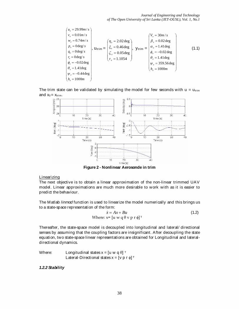
The trim state can be validated by simulating the model for few seconds with u = utrim
and x0 = xtrim.
Figure 2 - Nonlinear Aerosonde in trim
Linearizing The next objective is to obtain a linear approximation of the non-linear trimmed UAV model. Linear approximations are much more desirable to work with as it is easier to predict the behaviour. The Matlab linmod function is used to linearize the model numerically and this brings us to a state-space representation of the form:
BuAxx (1.2) Where: x= [u w q θ v p r ϕ] T
Thereafter, the state-space model is decoupled into longitudinal and lateral/directional senses by assuming that the coupling factors are insignificant. After decoupling the state equation, two state-space linear representations are obtained for Longitudinal and lateral-directional dynamics. Where: Longitudinal states x = [u w q θ] T
Lateral-Directional states x = [v p r ϕ] T 1.2.2 Stability
Journal of Engineering and Technology of The Open University of Sri Lanka (JET-OUSL), Vol. 1, No.1
39
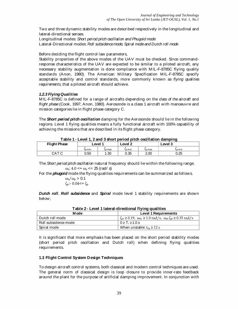
Two and three dynamic stability modes are described respectively in the longitudinal and lateral-directional senses. Longitudinal modes: Short period pitch oscillation and Phugoid mode Lateral-Directional modes: Roll subsidence mode, Spiral mode and Dutch roll mode Before deciding the flight control law parameters, Stability properties of the above modes of the UAV must be checked. Since command-response characteristics of the UAV are expected to be similar to a piloted aircraft, any necessary stability augmentation is done compliance with MIL-F-8785C flying quality standards (Anon, 1980). The American Military Specification MIL-F-8785C specify acceptable stability and control standards, more commonly known as flying qualities requirements, that a piloted aircraft should achieve. 1.2.3 Flying Qualities MIL-F-8785C is defined for a range of aircrafts depending on the class of the aircraft and flight phase (Cook, 1997; Anon, 1980). Aerosonde is a class 1 aircraft with manoeuvre and mission categories lie in flight phase category C. The Short period pitch oscillation damping for the Aerosonde should lie in the following regions. Level 1 flying qualities means a fully functional aircraft with 100% capability of achieving the missions that are described in its flight phase category.
Table 1 - Level 1, 2 and 3 short period pitch oscillation damping Level 1 Level 2 Level 3 Flight Phase
ζs min ζs max ζs min ζs max ζs min CAT C 0.50 1.30 0.35 2.00 0.25
The Short period pitch oscillation natural frequency should lie within the following range.
ωs: 4.0 <= ωs <= 25 (rad/s) For the phugoid mode the flying qualities requirements can be summarized as follows.
ωs/ωp > 0.1 ζp:- 0.04<= ζp
Dutch roll, Roll subsidence and Spiral mode level 1 stability requirements are shown below;
Table 2 - Level 1 lateral-directional flying qualities Mode Level 1 Requirements
Dutch roll mode ζdr ≥ 0.19, ωdr ≥ 1.0 rad/s, ωdr ζdr ≥ 0.35 rad/s Roll subsidence mode 0 ≥ Tr ≥ 1.0 s Spiral mode When unstable: t2ϕ ≥ 12 s It is significant that more emphasis has been placed on the short period stability modes (short period pitch oscillation and Dutch roll) when defining flying qualities requirements. 1.3 Flight Control System Design Techniques To design aircraft control systems, both classical and modern control techniques are used. The general norm of classical design is loop closure to provide inner-rate feedback around the plant for the purpose of artificial damping improvement. In conjunction with
Journal of Engineering and Technology of The Open University of Sri Lanka (JET-OUSL), Vol. 1, No.1
40
this, standard integral compensator structures are used to eliminate steady state errors. Modern control techniques on aircraft FCSs have been employed since mid 80’s (Stevens and Lewis, 1992). However, modern techniques are not highly encouraged on aircraft control due to their dependency on selecting large number of parameters such as performance index weighting matrices. There are many classical Command and Stability Augmentation Systems developed for aircraft control such as Longitudinal Rate Command Attitude Hold (RCAH) controller, C* controller (Example: A320), C*-U controller and Lateral-Directional Auto-stabilizer (LDA) controller etc. 1.3.1 Longitudinal Flight Control System Design The RCAH controller has been used for longitudinal control of the Aerosonde as the dynamic structure of the aircraft and its stability and control characteristics should remain classical. One reason for this is that classical control and stability characteristics can easily be tuned in compliance with the Flying Quality standards. In addition, when controlling the UAV on the Simulation or Real-Time the human intuition appreciates classical command-response characteristics. This RCAH design has been successfully used on F-16 fighter jet. 1.3.2 Lateral-Directional Flight Control System Design The LDA controller is proposed to use for lateral and directional control of the UAV with the same reasoning as mentioned above. Since the trim state is assumed in both lateral and directional senses, the LDA design is mainly concerned with manoeuvring the UAV about the trim state. 2 LONGITUDINAL FLIGHT CONTROL SYSTEM DESIGN As mentioned in the introduction, the linearized longitudinal state-space representation of the trim state can be shown as below (For elevator inputs only).
0 46.308-3.4212-0.2976-
0 1.0000 0 0 0 5.7174- 5.2290- 0.3421
0.2404- 29.3296 4.9550- 0.5318-9.7973- 0.7248- 0.4017 0.2690-
qwu
qwu
(2.1)
2.1 Flying qualities requirements With reference to MIL-F-8785C, the longitudinal flying qualities are analysed.
Table 3 - Open loop level 1 longitudinal flying qualities Mode Level 1 Requirements Aerosonde
Short Period Pitch Oscillation 0.5 ≥ ζs ≥ 1.30 4.0 <= ωs <= 25 (rad/s)
ζs = 0.396 ωs = 13.5 rad/s
Phugoid mode ωs/ωp > 0.1 0.04<= ζp
ωs/ωp = 27.6 ζp = 0.274
It is clear that the short period damping is too low while the mode frequency meets the requirements. The phugoid mode flying qualities requirements are already well within
Journal of Engineering and Technology of The Open University of Sri Lanka (JET-OUSL), Vol. 1, No.1
41
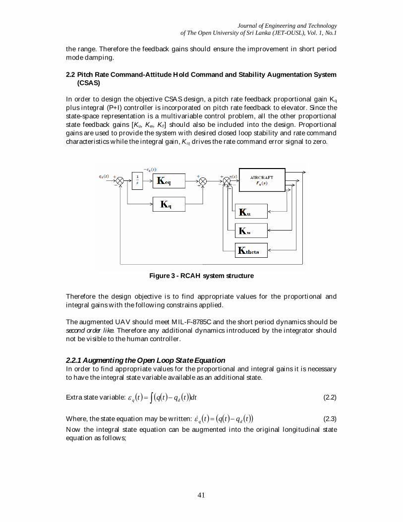
the range. Therefore the feedback gains should ensure the improvement in short period mode damping. 2.2 Pitch Rate Command-Attitude Hold Command and Stability Augmentation System
(CSAS) In order to design the objective CSAS design, a pitch rate feedback proportional gain Kq plus integral (P+I) controller is incorporated on pitch rate feedback to elevator. Since the state-space representation is a multivariable control problem, all the other proportional state feedback gains [Ku, Kw, Kθ] should also be included into the design. Proportional gains are used to provide the system with desired closed loop stability and rate command characteristics while the integral gain, Kεq drives the rate command error signal to zero.
Figure 3 - RCAH system structure
Therefore the design objective is to find appropriate values for the proportional and integral gains with the following constrains applied. The augmented UAV should meet MIL-F-8785C and the short period dynamics should be second order like. Therefore any additional dynamics introduced by the integrator should not be visible to the human controller.
2.2.1 Augmenting the Open Loop State Equation In order to find appropriate values for the proportional and integral gains it is necessary to have the integral state variable available as an additional state. Extra state variable: dttqtqt dq (2.2)
Where, the state equation may be written: tqtqt dq (2.3) Now the integral state equation can be augmented into the original longitudinal state equation as follows;
Journal of Engineering and Technology of The Open University of Sri Lanka (JET-OUSL), Vol. 1, No.1
42
d
qqwu
qwu
10000
0 0
46.308-3.4212-0.2976-
0 0 1.0000 0 0 0 0 1.0000 0 0 0 0 5.7174- 5.2290- 0.34210 0.2404- 29.3296 4.9550- 0.5318-0 9.7973- 0.7248- 0.4017 0.2690-
(2.4)
Then the open loop longitudinal state equation may be written as;
NvBuAxx (2.5) 2.2.2 Designing the closed loop system stability The feedback control law can be defined as follows;
MvKxu (2.6) where K is the feedback gain vector and M is the feed forward gain scalar which is assumed to be 1 at this instance (therefore no feed forward gain is illustrated in Figure 1). By substituting the control law into the previous state representation the closed loop state-space equation is obtained in the general form.
vNBMxBKAx ][][ (2.7) where K= [Ku Kw Kq Kθ Kεq]
Now the task is to select an appropriate feedback gain vector K such that it provides level 1 flying qualities in compliance with MIL-F-8785C and objective command-response characteristics. This has been achieved by solving a Linear Quadratic Regulator (LQR) control problem. LQR control problem If the open loop state-space representation is BuAxx , the problem is to find an optimal constant feedback controller K0 such that it minimizes the following quadratic cost function.
0
))()()()(( dttRututQxtxJ TT (2 .7)
where MvKxtu )( , Q and R are weighting matrices. LQR Solution: The Optimal controller is PBRK T
o1 (2.8)
where 0 TPP is the solution of 01 QPBPBRPAPA TT (2.9)
Matrix P is a positive definite (or semi-definite) matrix where 0PxxT for all .0x The choice of Q: As observed previously, it is desired to obtain level 1 flying qualities of the short period mode and pitch rate command-attitude hold characteristics. The short period mode is significant (dominant) in w and q responses while the integral action is critical in command-response characteristics and therefore Q can be selected such that it
Journal of Engineering and Technology of The Open University of Sri Lanka (JET-OUSL), Vol. 1, No.1
43
gives a considerable emphasis on Kw, Kq and Kεq gains and less emphasis on Ku and Kθ gains. After a series of trials the following Q matrix was selected.
100,1010,1010,1010,1010 104410 diagQ R is selected to be 1 to correctly scale the control inputs. After solving the above problem on Matlab the optimal feedback gain vector was found to be;
K= [-0.0092 0.0897 -0.4535 -0.0120 -9.9799] Closed loop system analysis The closed loop state equation,
d
qqwu
qwu
1.0000- 0
111.1390 8.2109 0.7142
0 0 1.0000 0 0 0 0 1.0000 0 0 462.1459- 0.5560- 26.7158- 1.0763- 0.0860-34.1431- 0.2815- 27.7783 4.6482- 0.5634-2.9700- 9.8009- 0.8597- 0.4284 0.2718-
(2.10)
w and q transfer functions:
502.5) + 27.16s + (s 0.3297)+(s 4.15)+(s s0.3284)+(s 4.511)+(s 9.98)-(s s 46.3079-
)(qq(s)
2d
s
502.5) + 27.16s + (s 0.3297)+(s 4.15)+(s s 0.1813) + 0.2756s + (s 9.98)-(s 402.7)+(s 3.4212-
)()(
2
2
sqsw
d
The closed loop integral lag pole is at (s + 4.15), which equates to a lag time of 0.241 seconds. Thus even if the lag is visible to the pilot it is less intrusive as it is much faster. However, the effect of the integral lag time constant can be diminished by a proper selection of M feed forward gain. 2.2.3 Designing the feed forward gain Up to now M was taken to be 1, since no information about the integrator pole was available. The feed forward gain determines the integral zero. Since the feedback gain vector K is known, the closed loop state equation may now be written as;
d
qqwu
qwu
1.0000- 0M
111.139M 8.2109M 0.7142M
0 0 1.0000 0 0 0 0 1.0000 0 0
462.1459- 0.5560- 26.7158- 1.0763- 0.0860-34.1431- 0.2815- 27.7783 4.6482- 0.5634-2.9700- 9.8009- 0.8597- 0.4284 0.2718-
(2.13)
It can easily be shown that integral zero is given by;

Journal of Engineering and Technology of The Open University of Sri Lanka (JET-OUSL), Vol. 1, No.1
44
MK
z q , since the integral gain is -9.9799 and integral pole is at 4.15, M = -2.4
w and q transfer functions with the feed forward gain M:
502.5) + 27.16s + (s 0.3297)+(s 4.15)+(s s 0.1813) + 0.2756s + (s 4.151)+(s 402.7)+(s 8.2246
)()(
2
2
sqsw
d
502.5) + 27.16s + (s 0.3297)+(s 4.15)+(s s0.3284)+(s 4.151)+(s 4.511)+(s s 111.3242
)(qq(s)
2d
s
Inspection of equations indicates that cancellation of the integral pole is exact and therefore the short period mode is second order like. The dynamics introduced by the integrator is not visible to the human controller. The stability characteristics of the closed loop UAV can be shown as follows;
Table 4 - Closed loop level 1 Longitudinal flying qualities Mode Closed Loop Aerosonde
Short Period Pitch Oscillation ζs = 0.606 ωs = 22.4 rad/s
Phugoid mode T1= 1/0 = s T2= 1/0.3297 = 3.03 s
Integrator lag Tlag = 1/4.15 = 0.241 s It is clear that the closed loop UAV holds level 1 flying qualities with the implemented controller. However, a significant change in the phugoid mode can be seen due to the integral feedback. The significant variable of the phugoid mode is θ and the integral of the pitch rat is also pitch attitude θ. Therefore, due to the change in q feedback integral gain the closed loop phugoid mode has considerably modified. The mode is no longer oscillatory. However, a non-oscillatory phugoid is acceptable with reference to MIL-F-8785C technical literature (Anon, 1980). 2.2.4 Implementing the controller design The corresponding system structure can be realized as follows,
Figure 4 - Equivalent classical P+I controller
Journal of Engineering and Technology of The Open University of Sri Lanka (JET-OUSL), Vol. 1, No.1
45
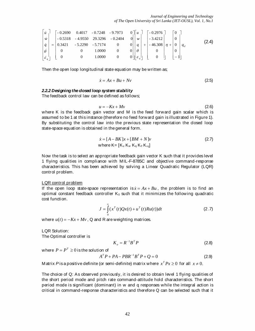
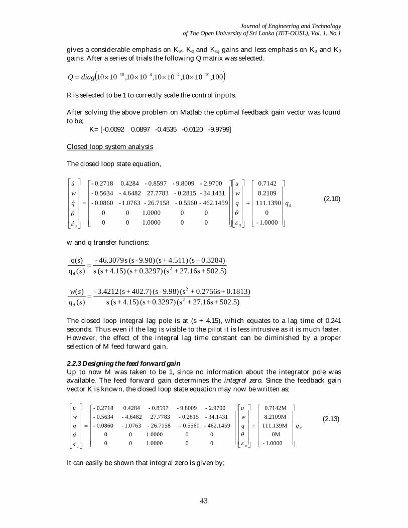
Response time histories
Figure 5 - Closed loop response to a 10 pitch rate demand
Figure 6 - Closed loop response to a 10 pitch rate demand of 3 second It is clear that the design objectives have been met successfully. The pitch rate responses like a well damped classical aircraft. When a demand for a pitch rate of 10/s is held for 3 seconds, the pitch attitude ramps up at 10/s and when the input is removed the attitude settles to 30 (Figure 6). This precisely describes the rate command-attitude hold characteristics of the design. 3 LATERAL-DIRECTIONAL FLIGHT CONTROL SYSTEM DESIGN The linearized lateral-directional state-space representation of the trim state for aileron and rudder inputs is shown below;
0 0 0 0
31.7508- 6.8154- 3.1102 172.8548-
5.0251 1.9687-
0 0 1.0003 0 0 0 0 0.0245 1.0000 0 0 0 1.2520- 3.2283- 0.8202 0 0 11.9786 24.8886- 5.0538- 0 9.7973 29.9906- 0.7358 0.7655-
rp
rpv
(3.1)
Journal of Engineering and Technology of The Open University of Sri Lanka (JET-OUSL), Vol. 1, No.1
46
Flying qualities requirements The MIL-F-8785C flying qualities requirements and Aerosonde lateral-directional mode stabilities are summarized as below;
Table 5 - Open loop level 1 lateral-directional flying qualities Mode Level 1 Requirements Aerosonde
Dutch roll mode ζdr ≥ 0.19 ωdr ≥ 1.0 rad/s
ωdr ζdr ≥ 0.35 rad/s
ζdr = 0.146 ωdr = 7.97 rad/s ωdr ζdr = 1.16 rad/s
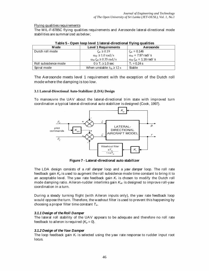
Roll subsidence mode 0 ≥ Tr ≥ 1.0 sec Tr = 0.24 s Spiral mode When unstable: t2ϕ ≥ 12 s Stable The Aerosonde meets level 1 requirement with the exception of the Dutch roll mode where the damping is too low. 3.1 Lateral-Directional Auto-Stabilizer (LDA) Design To manoeuvre the UAV about the lateral-directional trim state with improved turn coordination a typical lateral-directional auto stabilizer is designed (Cook, 1997).
Figure 7 - Lateral-directional auto stabilizer
The LDA design consists of a roll damper loop and a yaw damper loop. The roll rate feedback gain Kp is used to augment the roll subsidence mode time constant to bring it to an acceptable level. The yaw rate feedback gain Kr is chosen to modify the Dutch roll mode damping ratio. Aileron-rudder interlinks gain Kari is designed to improve roll-yaw coordination in a turn. During a steady turning flight (with Aileron inputs only), the yaw rate feedback loop would oppose the turn. Therefore, the washout filter is used to prevent this happening by choosing a proper filter time constant Tw. 3.1.1 Design of the Roll Damper The lateral roll stability of the UAV appears to be adequate and therefore no roll rate feedback to aileron is required (Kp = 0). 3.1.2 Design of the Yaw Damper The loop feedback gain Kr is selected using the yaw rate response to rudder input root locus.
Journal of Engineering and Technology of The Open University of Sri Lanka (JET-OUSL), Vol. 1, No.1
47
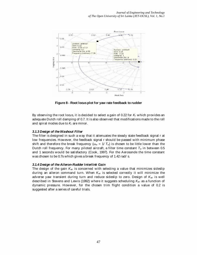
Figure 8 - Root locus plot for yaw rate feedback to rudder By observing the root locus, it is decided to select a gain of 0.22 for Kr which provides an adequate Dutch roll damping of 0.7. It is also observed that modifications made to the roll and spiral modes due to Kr are minor. 3.1.3 Design of the Washout Filter The filter is designed in such a way that it attenuates the steady state feedback signal r at low frequencies. However, the feedback signal r should be passed with minimum phase shift and therefore the break frequency (ωw = 1/Tw) is chosen to be little lower than the Dutch roll frequency. For many piloted aircraft, a filter time constant Tw in between 0.5 and 1 seconds would be satisfactory (Cook, 1997). For the Aerosonde the time constant was chosen to be 0.7s which gives a break frequency of 1.42 rad/s. 3.1.4 Design of the Aileron-Rudder Interlink Gain The design of the gain Kari is concerned with selecting a value that minimizes sideslip during an aileron command turn. When Kari is selected correctly it will minimize the adverse yaw transient during turn and reduce sideslip to zero. Design of Kari is well described in Stevens and Lewis (1992) where it suggests scheduling Kari as a function of dynamic pressure. However, for the chosen trim flight condition a value of 0.2 is suggested after a series of careful trials.
Journal of Engineering and Technology of The Open University of Sri Lanka (JET-OUSL), Vol. 1, No.1
48
Response time histories
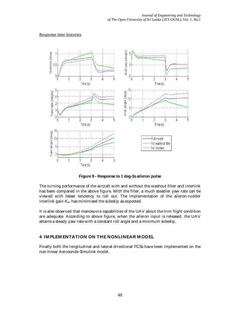
Figure 9 - Response to 1 deg-3s aileron pulse The turning performance of the aircraft with and without the washout filter and interlink has been compared in the above figure. With the filter, a much steadier yaw rate can be viewed with lesser tendency to roll out. The implementation of the aileron-rudder interlink gain Kari has minimised the sideslip as expected. It is also observed that manoeuvre capabilities of the UAV about the trim flight condition are adequate. According to above figure, when the aileron input is released, the UAV attains a steady yaw rate with a constant roll angle and a minimum sideslip. 4 IMPLEMENTATION ON THE NONLINEAR MODEL Finally both the longitudinal and lateral-directional FCSs have been implemented on the non-linear Aerosonde Simulink model.
Journal of Engineering and Technology of The Open University of Sri Lanka (JET-OUSL), Vol. 1, No.1
49
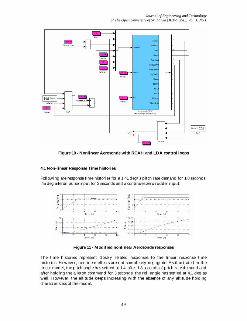
Figure 10 - Nonlinear Aerosonde with RCAH and LDA control loops 4.1 Non-linear Response Time histories Following are response time histories for a 1.41 deg/s pitch rate demand for 1.8 seconds, .45 deg aileron pulse input for 3 seconds and a continues zero rudder input.
Figure 11 - Modified nonlinear Aerosonde responses The time histories represent closely related responses to the linear response time histories. However, nonlinear effects are not completely negligible. As illustrated in the linear model, the pitch angle has settled at 1.4 after 1.8 seconds of pitch rate demand and after holding the aileron command for 3 seconds, the roll angle has settled at 4.1 deg as well. However, the altitude keeps increasing with the absence of any altitude holding characteristics of the model.
Journal of Engineering and Technology of The Open University of Sri Lanka (JET-OUSL), Vol. 1, No.1
50
5 CONCLUSIONS The full nonlinear Aerosonde model has been trimmed and linearized in order to apply the objective control schemes in compliance with MIL-F-8785C flying qualities requirements to enable the UAV to be controlled by a human operator. Two control schemes were developed in the longitudinal and lateral-directional senses on the linearized model and later the designs were tested on the nonlinear model. The control techniques used for the design are classical theories with the exception of LQR techniques. The FCSs has been proved, to work properly on nonlinear simulation, and to provide command-response characteristics that of a classical piloted aircraft. However, the design doesn’t contain speed and altitude auto-control loops and therefore a constant controlling of the engine throttle is required to maintain the airspeed and altitude. In addition, the FCS parameters have been decided for the chosen trim flight condition. Hence for the design to work over a larger flight envelop, the FCS parameters should be scheduled for changing flight conditions (gain scheduling). Further this design can be extended to have robust, optimal and path planning control algorithms. ACKNOWLEDGEMENTS Author would like to acknowledge Mr. P.G.D. Siriwardana, Mr. Achintha Madushanka and Mr. H.R. Jayathilaka for giving me their support and assistance throughout this work. REFERENCES [1] Cook, M. V. (1997) Flight Dynamics Principles. Butterworth Heinemann., Oxford,
England. [2] Anon (1980) Military Specification- Flying Qualities of Piloted Aeroplane, MIL-F-
8785C. Department of Defense, USA. [3] Stevens, B. L. and Lewis, F.L. (1992) Aircraft Control and Simulation. John Wiley &
Sons, Inc., New York. [4] Cowling, I. (2008) Towards Autonomy of a Quadrotor UAV. Cranfield University,
England. [5] Nelson, R.C. (1989) Flight Stability and Control. McGraw-Hill, Inc., USA. [6] Blakelock, J.H. (1991) Automatic Control of Aircraft and Missiles. John Wiley & Sons,
Inc., New York. [7] Carnduff, S., Erbsloeh, S.D., Cook, M. V., and Cooke A.K. (2007) Experimental
Investigation into UAV Flight Dynamics., 22nd International UAV Systems Conf. [8] Skogestad, S., and Postlethwaite, I. (1996) Multivariable Feedback Control. John
Wiley & Sons, Inc., New York. [9] Skogestad, S., and Postlethwaite, I. (1996) Multivariable Feedback Control. John
Wiley & Sons, Inc., New York. [10] Tennakoon, M.S., and Munasinghe, R., (2008) Design and Simulation of a UAV
controller system with high manoeuvrability.


![UKACC International Conference on Control 2012 Cardiff, …€¦ · · 2012-08-29Design and Implementation of Real-Time Control System Using RTAI and Matlab/RTW ... ,uCos[7],QNX[8]](https://img.pdfslide.net/doc/110x75/5abeeb347f8b9a8e3f8d9bbf/ukacc-international-conference-on-control-2012-cardiff-2012-08-29design-and.jpg)