Embed Size (px)
Citation preview

Louisiana State UniversityLSU Digital Commons
LSU Master's Theses Graduate School
2008
Design of a Fully Autonomous Mobile PipelineExploration Robot (FAMPER)Jong-Hoon KimLouisiana State University and Agricultural and Mechanical College, [email protected]
Follow this and additional works at: https://digitalcommons.lsu.edu/gradschool_theses
Part of the Computer Sciences Commons
This Thesis is brought to you for free and open access by the Graduate School at LSU Digital Commons. It has been accepted for inclusion in LSUMaster's Theses by an authorized graduate school editor of LSU Digital Commons. For more information, please contact [email protected].
Recommended CitationKim, Jong-Hoon, "Design of a Fully Autonomous Mobile Pipeline Exploration Robot (FAMPER)" (2008). LSU Master's Theses. 1284.https://digitalcommons.lsu.edu/gradschool_theses/1284

DESIGN OF A FULLY AUTONOMOUS MOBILE PIPELINE EXPLORATION ROBOT
(FAMPER)
A Thesis
Submitted to the Graduate Faculty of the
Louisiana State University and
Basic Science College
in partial fulfillment of the
requirements for the degree of
Master of Science in System Science
in
The Department of Computer Science
by
Jong-Hoon Kim
B.E., Seoul National University of Technology in Seoul, South Korea, 2005
December 2008

ACKNOWLEDGEMENTS
I am pleased to thank the many people who made this thesis possible. I cannot imagine
this thesis without their generous help. I will remember, and appreciate their contributions
forever. I would like to deeply thank Dr.Iyengar. He has enhanced my confidence, motivation,
and always inspired me. With his support I could complete this thesis. I wish to express sincere
thanks to Dr.Ullmer, both for his advice, and also for letting me use the equipments in the
Tangviz Lab generously. I am deeply grateful to Dr.El-Amawy, both for his support, and trust in
me and my work. Once again I would like to thank them all for being on my committee. I
would also like to extend my sincere thanks to Dr. Paramesh for his suggestions and help me
wind up my thesis.
I would like to thank my friends, Bhaskar, Rajesh, Lohit and Bharat. Bhaskar and Lohit
for their selfless help with Linux and Gumstixs, long hours of discussion and brain-storming on
design issues, and for painstakingly proof reading parts of my thesis. Thanks to Rajesh for initial
discussions on robot designs, and also engineering support. Bharat, my lab mate, gave me many
technical advices to successfully complete this thesis. I would like to thank YoungPyo Jeon, my
best friend. He made it very easy to come to a new country and start a life. Thanks to Jeong-Tae
Ok, Jihwan Park, SeoungHoon Park, Hee-Joung An, Yunmi Jeon, Hana Kim, Doan Kim,
Srikanth, Monika, Archana, Balachandran and many others for your company, support, and for
making my life in Baton Rouge enjoyable.
Finally, I would give great appreciation to my family. They always gave me
unquestioning faith and encouraged me in every time. Especially, I would love to express to
Keyyoung Park, my wife, my gratitude for her enormous support and devotion. Without her
sacrifices, I couldn’t have done this all and this thesis is dedicated to her.
ii

TABLE OF CONTENTS
ACKNOWLEDGEMENTS ............................................................................................................ ii
LIST OF TABLES ......................................................................................................................... v
LIST OF FIGURES ........................................................................................................................ vi
ABSTRACT ................................................................................................................................. viii
1. INTRODUCTION ....................................................................................................................... 1
1.1 Robot in Real World Domains ............................................................................................. 1
1.2 The Pipeline Domain ............................................................................................................ 2
1.2.1 Oil Pipelines ................................................................................................................. 3
1.2.2 Ethanol Pipelines ......................................................................................................... 4
1.2.3 Hydrogen Pipelines ...................................................................................................... 4
1.2.4 Water Pipelines ............................................................................................................ 5
1.3 Sewer/Plumbing Pipeline Robot Domain ............................................................................ 5
1.4 Navigations within Pipelines ................................................................................................ 7
2. BACKGROUND ......................................................................................................................... 9
2.1 Mechanical Classifications ................................................................................................... 9
2.2 Autonomy Based Classifications ....................................................................................... 12
2.2.1 Non Autonomous Robots ........................................................................................... 13
2.2.2 Semi Autonomous Robots .......................................................................................... 13
2.2.3 Fully Autonomous Robots ......................................................................................... 14
2.3 Challenges in Pipeline Robot Navigation .......................................................................... 16
2.3.1 Mechanical Challenges .............................................................................................. 16
2.3.2 Electrical Challenges .................................................................................................. 17
2.3.3 Programming Challenges ........................................................................................... 18
2.3.4 Application Challenges .............................................................................................. 18
3. DESIGN OF A FULLY AUTONOMOUS PIPELINE EXPLORATION ROBOT ................ 20
3.1 Design Features .................................................................................................................. 21
3.2 The Wall-Press Caterpillar Mechanism ............................................................................. 21
3.2.1 Continuous Track: Caterpillar .................................................................................... 21
3.2.2 Independently Enlargeable Suspension Link Model .................................................. 22
3.2.3 Caterpillar Vs Other Mechanisms .............................................................................. 25
3.3 FAMPER Operational Architecture ................................................................................... 25
3.4 Control Methods for Three Dimensional Movement in Pipelines ..................................... 28
3.5 FAMPER’s Electrical Architecture .................................................................................... 33
3.5.1 Sensor and Controller ................................................................................................. 33
3.5.2 Interface Board ........................................................................................................... 34
3.5.3 Expansion Board ........................................................................................................ 34
3.5.4 Gumstix Main Board .................................................................................................. 34
3.5.5 Application ................................................................................................................. 35
3.6 Hardware System for a Fully Autonomous Navigating System ........................................ 35
iii

3.6.1 Gumstix ...................................................................................................................... 36
4. IMPLEMENTATION OF FAMPER ........................................................................................ 38
4.1 FAMPER’s Disassembly ................................................................................................... 38
4.2 FAMPER’s Mechanical Platform ...................................................................................... 39
4.2.1 Caterpillar ................................................................................................................... 40
4.2.2 Flexible and Independent Links and Suspensions...................................................... 41
4.2.3 Skeletal Body Frame .................................................................................................. 41
4.3 FAMPER’s Electrical Platform .......................................................................................... 42
4.4 Electronic Architecture ...................................................................................................... 43
4.5 FAMPER Manual Control Program ................................................................................... 45
4.6 FAMPER Controller: FC ................................................................................................... 46
4.7 RF Video System ............................................................................................................... 46
5. EXPERIMENTAL EVALUATION ......................................................................................... 47
5.1 Elbow – 45 ......................................................................................................................... 47
5.2 Elbow – 90 ......................................................................................................................... 47
5.3 Branch T ............................................................................................................................. 48
5.4 Branch Y ............................................................................................................................ 49
5.5 Complex Pipeline Layout ................................................................................................... 50
5.6 FAMPER’s Performance Result ........................................................................................ 51
6. DISCUSSION ........................................................................................................................... 53
6.1 Mechanics........................................................................................................................... 53
6.2 Electronics .......................................................................................................................... 54
6.3 FAMPER System Programming ........................................................................................ 54
6.4 Environmental Concerns .................................................................................................... 55
7. CONCLUSION ......................................................................................................................... 56
REFERENCES .............................................................................................................................. 58
APPENDIX I : SCHEMATICS OF FAMPER ............................................................................. 60
A. Mechanical Schematics ....................................................................................................... 60
A-1 Robot Body .................................................................................................................. 60
A-2 Caterpillar Frame ......................................................................................................... 61
A-3 Links and Gears ........................................................................................................... 62
B. ELECTRICAL SCHEMATICS OF INTERFACE BOARD .............................................. 63
C. PCB OF INTERFACE BOARD ......................................................................................... 63
D. DETAILED GUMSTIX MOTHERBOARD SPECIFICATION ....................................... 64
APPENDIX II : GUMSTIX AND ROBOSTIX BASICS ............................................................ 65
A. Gumstix Basics .................................................................................................................... 65
B. Robostix Basics ................................................................................................................... 72
VITA ............................................................................................................................................. 77
iv

LIST OF TABLES
Table 1 - Forty five (45) degree elbow ........................................................................................ 30
Table 2 - Ninety (90) degree elbow ............................................................................................. 30
Table 3 - T–Branch ...................................................................................................................... 31
Table 4 - Y-Branch ........................................................................................................................ 32
Table 5 - Benchmark result of Gumstix PXA-270 with Pentium 90 and AMD K6/ 233 ............ 37
Table 6 - Inclination angle Vs. time for 4 feet straight pipeline .................................................. 51
Table 7 - Performance change with different elbows in 4 feet length ......................................... 51
Table A.1 - Detailed Gumstix motherboard specification ........................................................... 64
Table B.1 - UART ........................................................................................................................ 74
Table B.2 - Analog to digital (A/D) ............................................................................................. 74
Table B.3 - Port-C of Robostix .................................................................................................... 75
v
LIST OF FIGURES
Figure 1 - Welding robot in car factory, electronics assembling robot and surgery robot ............. 1
Figure 2 - Floor cleaning robot, landmine removing robot and gas pipeline inspection robot ....... 2
Figure 3 - Oil pipeline in Alaska ..................................................................................................... 3
Figure 4 - PIGS and SCRAPERS for oil pipeline inspection ......................................................... 4
Figure 5 - Man unclogging sewer overflow, Chennai, India .......................................................... 7
Figure 6 - Mechanical classification of pipeline robots .................................................................. 9
Figure 7 - Typical methods of steering in branch ......................................................................... 11
Figure 8 - Examples of non autonomous robots ........................................................................... 13
Figure 9 - Examples of semi autonomous robots .......................................................................... 14
Figure 10 - Examples of fully autonomous robots ........................................................................ 15
Figure 11 - FAMPER's design feature .......................................................................................... 20
Figure 12 - Model and feature of FAMPER's link mechanism ..................................................... 23
Figure 13 - Front view of FAMPER's link system ........................................................................ 25
Figure 14 - Flow-diagram for FAMPER’s operational architecture ............................................. 27
Figure 15 - Mode of FAMPER’s operation .................................................................................. 28
Figure 16 - Front view of FAMPER ............................................................................................. 29
Figure 17 - Block diagram of FAMPER’s electrical architecture ................................................. 33
Figure 18 - Initial structural design of FAMPER .......................................................................... 38
Figure 19 - First prototype of FAMPER ....................................................................................... 38
Figure 20 - FAMPER version 1.0 ................................................................................................. 38
Figure 21 - Disassembly of FAMPER .......................................................................................... 39
Figure 22 - Feature of caterpillar tracks ........................................................................................ 40
Figure 23 - Feature of links and suspensions ................................................................................ 41
vi

Figure 24 - Feature of central body frame ..................................................................................... 42
Figure 25 - FAMPER's electrical disassembly .............................................................................. 43
Figure 26 - Block-diagram of implemented electrical architecture .............................................. 44
Figure 27 - Feature of manual control program ............................................................................ 45
Figure 28 - Simple FAMPER controller: FC ................................................................................ 46
Figure 29 - RF video system ......................................................................................................... 46
Figure 30 - Test-bed of 45 degree elbow ...................................................................................... 47
Figure 31 - Test-bed of 90 degree elbow ...................................................................................... 48
Figure 32 - Test-bed of branch-T .................................................................................................. 49
Figure 33 - Test-bed of branch-Y .................................................................................................. 49
Figure 34 - Test-bed complex pipeline layout .............................................................................. 50
Figure A.1 - Robot body mechanical schematics .......................................................................... 60
Figure A.2 - Caterpillar frame mechanical schematics ................................................................ 61
Figure A.3 - Link and gear mechanical schematics ...................................................................... 62
Figure A.4 - Electrical schematics of interface board ................................................................... 63
Figure A.5 - PCB of interface board ............................................................................................. 63
Figure B.1 - Front and rear view of Gumstix ................................................................................ 65
Figure B.2 - Front and rear view of Robostix ............................................................................... 73
vii

ABSTRACT
Pipelines have been an integral part of our constructions for many centuries. However,
need to be maintained, and the cost of maintenance continues to increase. Robots have been
considered as an attractive alternative, and many different types of pipeline robots have been
proposed in the past. Unfortunately many of them work under only very restricted environments
such as customized pipelines, often have no vertical mobility, or can traverse through only a
simple pipeline structure due to wired control.
This thesis presents the design and implementation of a robot based on novel idea we call
“caterpillar navigational mechanism”. A Fully Autonomous Mobile Pipeline Exploration Robot
(FAMPER), for exploring pipeline structures autonomously has been built and its performance
has been evaluated. We present the design of a robot based on wall-pressed caterpillar type for
not only horizontal, but also vertical mobility in pipeline elements such as straight pipelines,
elbows and branches, and its autonomous navigational system providing useful information for
pipeline maintenance.
FAMPER has been designed for 6 inch sewer pipes, which are predominantly used in
urban constructions. The proposed design enables FAMPER to display formidable mobility and
controllability in most of the existing structure of pipeline, and provides a spacious body for
housing various electronic devices. Specifically, FAMPER is equipped with several sensors, and
a high performance processor for autonomous navigation. We have performed experiments to
evaluate the effectiveness of our architecture and we present here a discussion of the performed
results.
viii
1
1. INTRODUCTION
1.1 Robot in Real World Domains
An automatically operated machine that replaces human effort was difficult to imagine;
in the view of appearance or perform functions in a humanlike manner. By extension, robotic
engineering deals with the design, construction, and operation of robots. A robot is a mechanical
or virtual artificial agent, which has a brain of its own. In practice, it is usually an electro-
mechanical system, which by its appearance or movements conveys a sense that it has intent or
agency of its own.
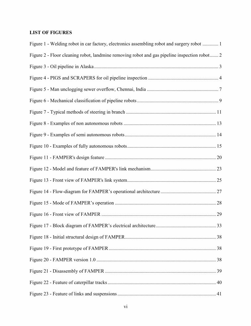
There were more than one million robots in operation worldwide in the first half of 2008,
with roughly half in Asia, 32% in Europe, 16% in North America, 1% in Australia and 1% in
Africa. Commercial and industrial robots are in widespread use, these robots performed jobs
with greater accuracy with no labor cost and more reliable than humans. Robots can be placed
into roughly two classifications based on the type of job they do. The first category includes
tasks which a robot can do with greater productivity, accuracy, or endurance than humans, and
the other category consists of doing dirty, dangerous or dull jobs which humans find undesirable.
Figure 1. Welding robot in car factory, electronics assembling robot and surgery robot

2
Figure 2. Floor cleaning robot, landmine removing robot and gas pipeline inspection robot
1.2 The Pipeline Domain
There are many areas where robots can be replaced for human; amongst them pipelines is
one of the most challengeable areas. Pipelines have been used in major utilities for long time.
Over billions of places from huge plants to an individual house, robots are employed by people.
But; many troubles like aging, corrosion, erosion, cracks and physical damages from third parties,
have occurred in pipelines. Therefore, maintenance of pipelines is essential in order to keep them
functional, and moreover the continuation cost for these activities are being increased.
Even with the above mentioned problems in pipeline, people still prefer them. The reason being,
pipelines are used in transporting substances through a mere pipe. Most of the time liquid and
gases are sent through pipes. Pneumatic tubes that transport solid capsules using compressed air
are also being used. Like gases and liquids, any chemically stable substance can be sent through
a pipeline. Hence sewage, slurry, water, and even beer pipelines exist. With this knowledge we
can classify pipelines with respect to the substance that it carries. We will look at each one in
detail.

3
1.2.1 Oil Pipelines
Dmitri Mendeleev in 1893 suggested pipelines for transporting Petroleum; most countries
have employed these pipelines. These pipes started to get widely used around the world. In the
year 2007, the total length of oil and gas pipelines in world was almost two millions km, and in
the United States had 793,285 km oil/gas pipelines. Pipelines are generally the most economical
way to transport large quantities of oil or natural gas
over land. Compared to railroad, they have lower cost
per unit with higher capacity.
The material used in manufacturing Oil pipes
are from steel or plastic tubes with inner diameter
typically varying from 4 to 48 inches. Most pipelines
are buried underground at a typical depth of about 3 to
6 feet. The oil is kept in motion by pump stations
along the pipeline, and usually flows at a speed of
about 1 to 6 m/s. Multi-product pipelines are used to transport two or more different products in
sequence on the same pipeline. Usually in multi-product pipelines there is no physical separation
between the different products. Some mixing of adjacent products occurs, producing interface.
This interface is removed from the pipeline at receiving facilities and segregated to prevent
contamination.
Oil contains varying amounts of wax, or paraffin. In colder climates wax accumulation
may occur within a pipeline. Often these pipelines are inspected and cleaned using pipeline
inspection gauges. There are varies gauges available like PIGS also known as SCRAPERS.
These devices are launched from PIG-launcher stations and travel through the pipeline to be
Figure 3. Oil pipeline in Alaska

4
received at any other station down-stream; Cleaning wax deposits and material that may have
accumulated along the line.
Figure 4. PIGS and SCRAPERS for oil pipeline inspection
1.2.2 Ethanol Pipelines
These pipelines are majorly used in Brazil and United States. There are several ethanol
pipeline projects in Brazil and the United States. Main problems related to the shipment of
ethanol by pipeline are its high oxygen content, which makes it corrosive, and absorption of
water and impurities in pipelines. Williams conducted an ethanol test in early 1980’s. Before the
test was conducted; PIGS were used in the pipeline. After the test a few suggestions were made
like; frequently dewatering of mainlines using PIGS and spheres, and using closed floater storage
tank to prevent rainwater ingestion.
1.2.3 Hydrogen Pipelines
The most cost-effective way to move gaseous hydrogen over a long distance is via pipeline.
Hydrogen pipeline is used for transportation of hydrogen through a pipe as part of the hydrogen
infrastructure. Hydrogen pipeline is used to connect the point of hydrogen production or delivery
of hydrogen with the point of demand, with transport costs similar to compressed natural gas
(CNG). Most hydrogen is produced at the place of demand with every 50 to 100 miles an

5
industrial production facility. The 1938 - Rhine-Ruhr 240 km hydrogen pipeline is still in
operation. As of 2004 there are 900 miles of low pressure hydrogen pipelines in the USA and
930 miles in Europe, In Hydrogen transportation, pipeline delivery pressures can go up to 700-
1,000 psi.
1.2.4 Water Pipelines
This is one of the most used pipelines all around the world and an ancient method as well.
The first people to transport water were the Romans to transport large aqueducts water from
higher altitudes by building the aqueducts in graduated segments that allowed gravity to simply
push the rushing water along until it reached its intended destination. As time passed by
hundreds of pipelines were built throughout Europe and elsewhere, and along with flour mills.
The ancient Chinese also made use of channels and pipe systems for public works. The infamous
Han Dynasty court eunuch Zhang Rang (189 AD) once ordered the engineer Bi Lan to construct
a series of square-pallet chain pumps outside the capital city of Luoyang. These chain pumps
serviced the imperial palaces and living quarters of the capital city as the water lifted by the
chain pumps were brought in by a stoneware pipe system. We will discuss water pipeline in
detail as we go on.
1.3 Sewer/Plumbing Pipeline Robot Domain
As we saw that pipelines are useful for transporting water for drinking or irrigation over
long distances when it needs to move over hills, or where canals or channels are poor choices
due to considerations of evaporation, pollution, or environmental impact. Plumbing derived from
the Latin plumbum for lead, is the skilled trade of working with pipes, tubing and plumbing
fixtures for drinking water systems and the drainage of waste. Plumbing is a piping system
constitutes the form of fluid transportation that is used to provide potable water to their homes

6
and business and also remove waste in the form of sewage. The plumbing industry is a basic and
substantial part of every developed economy, due to the need for clean water and proper
collection and transport of wastes.
A building's waste-disposal system has two parts: the drainage system and the venting
system. The drainage system, also called traps and drains, comprises pipes leading from various
plumbing fixtures to the building drain (indoors) and then the building sewer (outdoors). The
building sewer is then connected to a municipal sanitary sewage disposal system. Where
connection to a municipal sewage system is not possible, a local, private, code-approved septic
system is required. Cesspools and outhouses do not meet health codes.
Plumbing drainage and venting systems maintain neutral air pressure in the drains,
allowing flow of water and sewage down drains and through waste pipes by gravity. As such, it
is critical that a downward slope be maintained throughout. In relatively rare situations, a
downward slope out of a building to the sewer cannot be created, and a special collection pit and
grinding lift 'sewage ejector' pump are needed. By comparison, potable water supply systems
operate under pressure to distribute water up through buildings.
Water systems of ancient times relied on gravity for the supply of water, using pipes or
channels usually made of clay, lead or stone. Present-day water-supply systems use a network of
high-pressure pumps, and pipes are now made of copper, brass, plastic, steel, or other nontoxic
material. Present-day drain and vent lines are made of plastic, steel, cast-iron, and lead. Lead is
not used in modern water-supply piping due to its toxicity. The 'straight' sections of plumbing
systems are of pipe or tube. A pipe is typically formed via casting or welding, where a tube is
made through extrusion. Pipe normally has thicker walls and may be threaded or welded, where
tubing is thinner-walled and requires special joining techniques such as 'compression-fitting',

7
'brazing', 'crimping', or for plastics, 'solvent welding'.
1.4 Navigations within Pipelines
As mentioned above, pipelines have to be well maintained for sustaining their
functionality, although their material and structure engineering have remarkably improved for
the durability. Moreover, cost of the maintenance has been increased tremendously due to
increased length of pipelines. In addition, most of sewer pipelines are buried or hided into walls
for their protection and hiding their present in the surrounding. Thus, the pipeline accessibility to
human for maintenance activities
is very limited because many of
them are too small to work for
human. Even though there are few
big once, people don’t want to
work inside because of dirty as
well as hazardous. For example,
sewerage water can be overflowed when sewer pipelines are blocked by sludgy or dirty things. In
this case, blockages have to be removed from the pipe. Otherwise all areas can be spoiled by
dirty water due to outflow. There are several ways to remove these things. First, blocked pipes
can be penetrated with a long stick or wire but it is very difficult to do so when pipelines are bent.
Second, blockages can be blown out using air pressure, but it doesn’t work when pipe have
outlets or clacks between the blockage and starting point of air pressure. Third is an excavation
of the area which is suspected for clogging. The difficulty here is a finding clogged area and it
also takes long time and large cost. Now we can consider a pipeline robot at this situation. If a
pipeline robot can travel, find and remove these things in pipelines, we can significantly reduce
Figure 5. Man unclogging sewer overflow, Chennai, India

8
the recovery cost as well as time. We can avoid man power for these jobs. Therefore, a pipeline
robot can be a strongly recommendable solution for pipeline maintenance.
After introduction chapter, background is presented in chapter 3. Then FAMPER’s
concept and design is addressed in chapter 4. Implementation based on this is described in
chapter 5 and next experimental results are demonstrated in chapter 6. Finally, conclusion is
explained in chapter 7.

9
2. BACKGROUND
2.1 Mechanical Classifications
A pipeline exploration robot can be broadly classified into two types namely in-pipe and
out-pipe. We can clearly perceive that the out-pipe robots are a little less flexible than the in-pipe
robots. Also for the conditions which are being considered in the challenges mentioned above, an
out-pipe robot would be an in-appropriate choice, as the prime concentration of the FAMPER is
to deal with underground or in-wall conditions. So, the current robot “FAMPER” can be
classified as an in-pipe robot. Having said that, let us see how the in-pipe robots can be classified
into different sub-categories.
Figure 6. Mechanical classification of pipeline robots. [5]
With a considerable history behind the development of robotics, in-pipe robots can be coarsely
classified into seven different sub-categories, based on their applications. These are named as pig
type robot, wheel type robot, caterpillar type robot, wall-press robot, walking type robot,
inchworm type robot and screw type robot. Let us briefly discuss each one of them and their

10
probable applications.
Pig type robot as shown in fig 1(a) is one of the most popular commercial robots, which
don’t generally use additional driving utilities to move along the pipeline. This type of robot is
usually used when there is a sufficient flow in the pipeline, which can effectively aid and drive
the robot in phase with the flow in the pipeline. Practically this type of robot is used in pipelines
with large diameters [1]. Some modifications have been proposed to this type of robots by
adding a propeller that will basically make the robot cope up with the speed of the flow. Wheel
type robot as shown in fig. 1(b) is one of the basic types of robots, which is very much similar to
a plain mobile robot. And a considerable number of commercial robots have been reported for
implementing this specific classification [2], [3], [4], [5]. This type of robot is only applicable in
horizontal pipelines. One of the prime ways we could see on how to improve the present wheel
type robot is to add more gripping feature to the present wheel type robot. Apparently widening
the wheels a little bit and adding a band over those wheels can do this. This type is of a robot is
called Caterpillar type robot [6] as shown in fig. 1(c). Caterpillar type robots are usually used in
conditions that demand much more grip on the walls of the pipeline.
Wall-press type robot as shown in fig 1(d) is another type of in-pipe robot finding its
prime usage in vertical pipelines, which need some adequate force to be exerted on the walls of
the pipeline that will in turn prevent the robot from falling down. The advantages of wall-press
type robot correspond to the robot with flexible mechanism for pressing the wall by whatever
means they apply with [5], [7]. Walking type robot as depicted in fig. 1(e) is a robot with
articulated legs that will help the robot in movements that are highly sophisticated [8], [9]. This
type of robot usually has a complex design due to its sophisticated motion nature, so this design
not usually employed unless the pipeline where this is subjected to demands it. As shown in fig.

11
1(f), Inchworm type robot does in a way mimic the movement of a worm. Apparently this kind
of motion is slow and prefers smaller diameter pipelines [10], [11]. As the motion is slow we
cannot implement this model for pipelines that are longer in distance. Last but not the least
Screw type robot also called helical drive type robot as shown in fig. 1(g) is named after the
motion of this robot [12].
Now that we have seen all the different types of in-pine robots we can have a better
prejudice on what features should a given in-pipe robot possess in order for it to be efficient for
the job defined. At the same time the robot should perform the required task-space specifications
for which it has been designed, like exploring the pipeline. And also depending on the pipeline
for which the robot is being designed, we can implement multiple classifications of in-pipe
robots, such that the final in-pipe robot will efficiently tackle the complex layout of the pipeline.
The pipeline exploration robots existing today can traverse through the horizontal
pipelines but only a part of them can work their way out when the pipelines employ some
complex layout that avails one or more of elbows (also called L-Shaped bends) and vertical
pipelines. And even from those robots which successfully takes care of the previously mentioned
layouts, only a few of them will be able to tackle and negotiate the T-Shaped branches.
Figure 7. Typical methods of steering in branch. (a) Articulated active joint type: straight drive. (b) Articulated active joint type: steering drive. (c) Differential drive type: straight drive. (d) Differential drive type: steering drive [5]
12
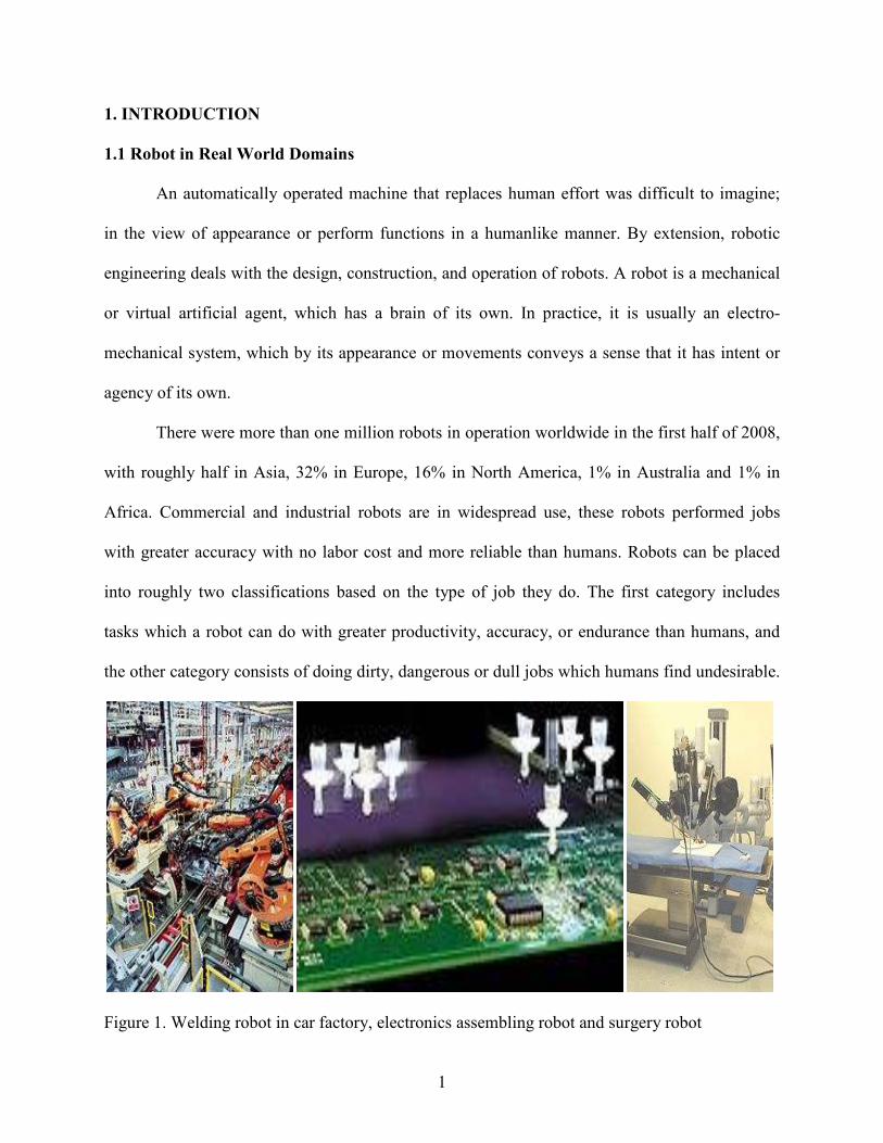
And a successful implementation of an in-pipe robot demands all these layouts to be
handled efficiently, as most of the practical pipeline layouts that exist today employ all these
special fittings like elbows, T-shaped branches, vertical pipes, Y-shaped branches etc. in the
complete layout of the pipeline structure.
Most of the robots described above also employ some kind of a steering functionality in
order to make the robot move. Though they employ specific steering procedures, all of these
procedures can be broadly categorized as Articulated-type drive and Differential drive types. The
articulated-type robot with active articulated joints is similar to those of a snake or annelid type
of reptile, which might be most adequate mechanism, even though the steering mechanism
becomes complicated to implement for steering joint [13] and double action universal joint [7].
The alternative way of steering is differential drive steering type as shown in fig. 2 (c) and (d),
where speeds of all the driving wheels are modulated in order to steer the robot in those special
fittings of the pipeline.
In order to cope up with all the problems and challenges mentioned above FAMPER is
designed to employ both the Caterpillar type and Wall-press type, so that it will be able to tackle
all those special fittings that are used in the modern pipeline layouts and also increases the
vertical mobility and enables the driving modules to change directions in the pipeline.
2.2 Autonomy Based Classifications
Autonomy as the word means by itself leads us to compromise on what different types of
sensors, extra hardware and computational equipments we might possibly need to make the robot
fully autonomous. Depending on the functionality of the robot, any given robot can be classified
as Non-autonomic, Semi Autonomic or Fully autonomic robot.
13
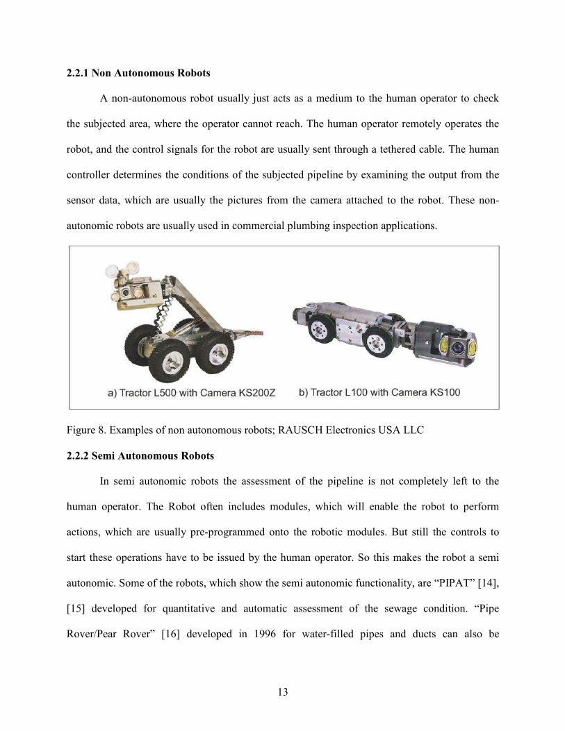
2.2.1 Non Autonomous Robots
A non-autonomous robot usually just acts as a medium to the human operator to check
the subjected area, where the operator cannot reach. The human operator remotely operates the
robot, and the control signals for the robot are usually sent through a tethered cable. The human
controller determines the conditions of the subjected pipeline by examining the output from the
sensor data, which are usually the pictures from the camera attached to the robot. These non-
autonomic robots are usually used in commercial plumbing inspection applications.
Figure 8. Examples of non autonomous robots; RAUSCH Electronics USA LLC
2.2.2 Semi Autonomous Robots
In semi autonomic robots the assessment of the pipeline is not completely left to the
human operator. The Robot often includes modules, which will enable the robot to perform
actions, which are usually pre-programmed onto the robotic modules. But still the controls to
start these operations have to be issued by the human operator. So this makes the robot a semi
autonomic. Some of the robots, which show the semi autonomic functionality, are “PIPAT” [14],
[15] developed for quantitative and automatic assessment of the sewage condition. “Pipe
Rover/Pear Rover” [16] developed in 1996 for water-filled pipes and ducts can also be

14
categorized as a semi autonomic robot.
Figure 9. Examples of semi autonomous robot
“KARO” [17] uses a tethered cable as a medium to transmit and receive signals from the
controller. It was primarily designed for sewer inspection and testing sensory equipment. So all
these robots can be categorized as semi autonomic as they do not have the ability to completely
perceive the condition of the pipeline without the prompt intervention from a human controller.
2.2.3 Fully Autonomous Robots
Fully autonomic robots are one such field where the research and development when
compared to the other robots is comparatively fewer than the research being done in other types
of robots. A Fully autonomic robot usually carries all the required modules that are required for
it to assess and process the condition of the pipeline. These are usually un-tethered robots, so all
the control signals are transmitted over a radio link. The control programs that usually run on the
on-board computing equipment take care of the robotic navigation and the decisions on the paths
to be followed by the robot. And time to time all the status messages are communicated to the
human inspector or an Artificial Intelligence unit over the radio link, so that if there are any
adjustments that are to be made can be communicated to the robot, so that those adjustments will

15
be adapted by the robot in further actions that will be taken by the robotic controllers. The
analysis of the acquired data can be done on the robot itself and/or can be transmitted to the
remote inspector for further processing. Only a few of the fully autonomic robots have been
developed for pipeline inspection, “KURT” [18] and “MAKRO” are two such robot platforms
for pipeline inspection that are designed for fully autonomic navigation in more or less cleaned
pipelines with diameters ranging from 300 mm to 600 mm, and under dry weather conditions.
KURT is able to navigate to ground level pipe junctions, was designed for inspecting pipelines
assisted by maps uploaded into the robot. MAKRO consists of six segments connected by five
motor driven active joints, these components enable it to simultaneously climb a step and turn in
the pipeline junctions. MAKRO was designed to establish that robots can navigate themselves
autonomously inside sewer pipelines.
Figure 10. Examples of fully autonomous robots
KANTARO [20] is another fully autonomous robot designed and developed in Japan for
navigating through sewer pipelines with varying inner diameter range of 8-12. But this robot
only considers the horizontal mobility and the vertical mobility have been ignored.
Although we have quite a few fully autonomous robots for pipelines, none of them
guarantee the usage and robustness to be safe and reliable in the pipeline. And most of these

16
robots include complex navigating mechanism and multiple sensors for motion control. There
are a lot of complexities involved in building the navigation mechanism and yet none of the
models implemented guarantee the reliability of the system, this makes these robots not to be
accepted by the commercial market, although PERMER was more or less successful in
implementing a robot for small range of pipes up to 6 inches in diameter.
FAMPER’s design is implemented in such a way that it has the ability to be a fully
autonomous robot. It has 23 ports for sensors, a high performance processor and big enough
memory to conduct all the processing that a pipeline layout demands to be performed on-board.
Also FAMPER is equipped with radio link modules, if should there be a requirement that needs
the sensor readings to be recorded and notified to a remote inspector. Thus all these features aid
FAMPER in becoming a fully autonomous robot.
2.3 Challenges in Pipeline Robot Navigation
2.3.1 Mechanical Challenges
The first and foremost challenge is mobility, a sewer pipeline robot should possess
excellent mobility and structure that will enable it to be flexible in horizontal, vertical or any
other type of special fitting that is employed in the pipeline layout. One big issue that has to be
considered deliberately is the ability to handle the vertical pipeline situations. Vertical pipeline
situations also introduce issues related to gravity, frictional force, rolling resistance etc. In
addition, layouts including vertical pipelines along with other branching special fittings will
complicate these real time issues. Moreover in a given complete pipeline network, we can
certainly expect the pipelines to grow and shrink in diameter. So in order to overcome these
kinds of situations the robot has to be flexible enough to tackle the challenges. FAMPER is
flexible to handle most of these situations, except for being adaptable to variable diameter

17
pipelines. But FAMPER can be extended in order to include this additional functionality. Most
of these real time complications get even more complicated if the subjected pipeline is spoiled or
damaged, in some cases this can even make the situations impossible for the robot to solve.
However, there are many researches being done and many new approaches are being proposed
for reliable accomplishment of mobility, which will always give us better conscience on which
particular approach to adapt.
Secondly, another challenge that would occur when dealing with in-pipe sewer pipelines
is to make the robot waterproof, because in most of the cases the pipeline is still partially filled
with some water that could bring up a potential problem in the operation of the robot. In order to
prevent such problems from arising, all the electrical devices should be properly insulated from
water.
Thirdly, space management is another issue, which for the most part decides the
adaptability of the robot in smaller diameter pipelines. In order to have good and powerful
system and additional equipment for increasing their performance, we need spacious body to
provide enough room for all these devices. But as the space itself is a limiting feature, we need to
find a tradeoff between size and performance.
2.3.2 Electrical Challenges
Firstly as mentioned previously in mechanical challenges section, space issues are to be
considered for robot’s performance. So, there is always a requirement for devices that are small
yet powerful. One such device is Gumstix, which is used in the implementation of the FAMPER.
We need to consider the applications and the goals for which the robot has been implemented,
while making the selections for the devices on which the robot will be built. For instance, if the
robot being designed is a pipeline exploration robot, which does the explorations using sonars,

18
then considerable amount of space have to be dedicated for housing powerful sonars.
Secondly accurate and reliable control system is a requirement for the robot to detect and
respond to the situations encountered in the subjected environment. Wireless connectivity has to
be maximized in order for the robot to transmit the sensor data to a remote inspector, so that the
processor included on-board can be used in doing things that are proximally demanding. The
sensors should be tuned such that the sensor dependent devices do not waste their processing
power in doing job for false triggers from the sensors. A good processor that is small yet
powerful enough along with large memory will definitely serve an added advantage in the
operation of the robot. Also as the robots have to be operated in conditions where providing
power becomes impossible without losing mobility, we need to use powerful batteries that could
power the robot and the attached components for a period of time. Selecting devices that have
low power consumption can increase them longevity reasonable.
2.3.3 Programming Challenges
Though the robot is fully autonomous it should be able to provide the required control
interface for the remote inspector in order to assess the performance of the robot. Also the robot
should be capable enough to learn and practically implement those learning in real time with the
help of Artificial Intelligence based controller software that helps in navigating autonomously.
The Software framework should be chosen in such a way that it would provide the
implementation of the software’s in multi coordinate system.
2.3.4 Application Challenges
Some of the possible applications for a pipeline-based robot could be, drawing blueprints
for pipelines that are under the ground or inside the walls by exploring through the pipeline
layout, and simultaneously generating the blueprint. Inspecting the pipelines for any damages

19
that have to be repaired and fixing them if possible. Cleaning the pipelines is most desirable for
maintenance of pipelines. Finding lost items in the pipelines is one of the most pleasing options
for general community.

20
3. DEIGN OF A FULLY AUTONOMOUS MOBILE PIPELINE EXPLORATION
ROBOT
FAMPER has three major goals in its concept and design. First and foremost thing is
mobility of FAMPER which will enable it to travel in horizontal, vertical conditions involving
with any kind of special fittings that a pipeline might be using for a 6 inch pipeline. Secondly the
operating architecture being used has to be simple yet flexible enough and adaptable enough for
the environment being considered. Thirdly it should be comprised of a powerful computing
system for handling navigational complications both autonomously as well as efficiently that
pipeline network might be having.
Figure 11. FAMPER's design feature
1) Wide track belt
2) Independent Suspension
3) Flexible Links
4) Spacious Body
5) A bird’s eye View
6) High resolution sensors
7) Centralized connections
8) Stacked Electrical Board
9) Powerful battery

21
3.1 Design Features
FAMPER has four caterpillar tracks that provide good gripping force in both vertical and
horizontal pipeline situations. Independent suspensions and links enable FAMPER to travel in
any type of pipeline network available. Spacious central body frame allows the ability of
installing powerful computing system. Centralized interface provides easily reachable
connections to many of the sensors that FAMPER uses. Powerful batteries help FAMPER to be
mobile, and also in increasing its ability to perform the given actions long enough in the given
mission range.
3.2 The Wall-Press Caterpillar Mechanism
3.2.1 Continuous Track: Caterpillar
The caterpillar tracks used here help the robot to distribute its weight evenly over a larger
surface of the track, when compared to the wheel-based robot. The caterpillar tracks have this
ability because as the tracked robot moves forward the segment which is used for the track is laid
out flat on the ground at the front and picked up again at the back. So this feature of the
caterpillar track helps the robot to handle the uneven surfaces much efficiently. The rollers at the
front and back of the robot, which aid in the movement of the rolling segment, take up the
additional load. The complete rolling track of the robot will help the robot in handling the
movement smoothly in loose areas, where the wheel-based robot of the same potential would fail
to do the job. Also the caterpillar-based robot will have additional grip provided from the rolling
segment in situations with surfaces having steeper gradients and slippery textures. We can see
that for equilibrium the ground pressure of a car must be equivalent to the pressure of the air in
the tires. For most of the cars this is around 30 psi (207 kPa), whereas for a seventy-ton M1
Abrams tank has the ground pressure of around 15 psi (103 kPa), which is exactly half that of the

22
car. Thus we can see that the caterpillar track helps the robot to exert less pressure on the
pipeline than when compared to the wheel-based robots in a horizontal pipeline. In case of a
vertical pipeline a wheel-based wall-press robot have to exert considerably more pressure on the
pipeline walls than when compared to the caterpillar-based wall-press robot, because the
caterpillar-based wall press robot have larger area in contact with the surface of the pipeline.
Also when passing onto any kind of special fittings from the vertical pipeline, a wheel-based
wall-press robot might lose its balance when the contact between its wheels and the pipeline
surface is lost, but in case of a caterpillar-based wall-press robot the rolling segment will always
have contact with the pipeline surface, so it will prevent this robot from loosing its balance.
Also as we have discussed before, the track-based robot will have better mobility than the
regular wheel-based robots over uneven surfaces, tracks smooth out the bumps and glide over
small obstacles. Tracks are less likely to get stuck up on the muddy surfaces as they distribute the
weight all over the rolling segment. Tracks can also give better mobility, as a track-based robot
can turn in its own radius by driving the tracks in opposite directions.
The main disadvantage with track-based robot is, tracks have lower top speeds due to
friction but this friction is necessary to vertical movement in pipeline. Tracks-based robots are
mechanically challenging, when compared to wheel-based robots. But caterpillar-based robots
cause lesser damage to the inner surface of the pipeline because of their smooth rolling surface,
than the wheel-based robots. Thus we can say that the advantages of using a caterpillar-based
robot will convince us enough to adapt track-based architecture for FAMPER.
3.2.2 Independently Enlargeable Suspension Link Model
In the mechanism used in the FAMPER, the distance between the central body and the
tracks can be determined based on the movement of the flexible links, the elastic restoration

23
force of the spring at the each suspension link, and reaction forces from the wall. From the above
figure.12 we can deduce the height of the track from the central body using the Pythagorean
Theorem, and the following equations can be derived,
Figure 12. Model and feature of FAMPER's link mechanism.
Here L1 is the length of the link connecting the track and the body also called
crank, another link of length ½ L1 connects the midpoint of the crank and the central body. Θxy
is the suspension angle between the crank and the central body of the robot. ∆x and ∆y are the
displacements along the x and y axes respectively. The vertical displacement of the track from
the central body can be calculated using the above equation involving the horizontal
displacement ∆x of the links on the central body. The force with which the tracks press on the

24
inner surface of the pipeline can be determined by adjusting the stiffness of the spring in the
initial stage of designing, and also the tractive force of the robot is determined accordingly. Since
the above-mentioned mechanism has been implemented in building FAMPER, we can be sure
that FAMPER will have effective contact with the inner surface of the pipeline, and also the
adaptable nature of the tracks and suspensions will make sure that FAMPER can sustain even in
conditions with uncertain pipeline conditions, as well as providing sufficient traction forces
during movements.
tan(θ) = ����
and by Pythagoreans’ theorem
��� ���� ����
��� �� �� �� ����� ����
��� ��� � ����� � �����
and also
� � ������������
Also FAMPER is additionally equipped with the capability of having suspension
independent of other suspension modules. In other words we can say that the track can move in
any particular way, in order to meet the subjected conditions and the pipeline situations. These
independent suspensions help the caterpillar track to be more flexible as shown in the pictures
below.
When the track meets any kind of obstacles, which only obstructs only a part of the track,
the track has the ability to be tilted for increasing the contact surface of the track. This feature of
having flexible tracks increases the gripping force of the track, which is very helpful in
conditions where pipelines are damaged.

25
Figure 13. Front view of FAMPER's link system
3.2.3 Caterpillar Vs Other Mechanisms
Pig type is not suitable in sewer pipeline network because it is difficult for it to turn in
elbows and branches as well as to move without sufficient driving flow by water or any carrier.
Thus, most of pig type robots are used in long and straight pipeline such as oil or gas pipelines.
Screw type also faces the difficulty in turning at elbows and branches. Wheel type has been used
for many different sewer pipeline robots but most of the sewer pipelines have some kind of dirt
on the inner walls that could make the movement of the wheels problematic. When wheel-type
robot is combined with wall-press type, it can have vertical mobility but, the exerted force on the
walls of the pipeline should be completely coming from the wheels, so if one of the wheels
looses contact from the inner pipeline surface, the robot might lose its balance. In general, it has
more simple mechanism than caterpillar type but caterpillar with wall-pressed type gives more
stable grip because of larges surface contact in vertical situations. Walking type robot can have
climbing ability but needs complicated mechanical and control systems. Especially, this type is
more difficult to make for small sized pipelines. Inchworm type is too slow to travel longer
distances. Thus, wall-press caterpillar type is best solution for sewer pipeline inspection robot.
3.3. FAMPER Operational Architecture
FAMPER’s operational architecture consists of three operator modules; Supreme
Operator, Perception Operator and Action Operator. Each operator has different manager
Left gradient track
Balanced track
Right gradient track

26
modules which perform fundamental operations with their own property values. The property
values are saved in a central repository which can be referred and updated by the module which
is accessing it and/or any other operator/s based on the rules formulated. This modular ability of
FAMPER’s architecture enables each module to be developed independently, for instance action
operator as we know only depends on the property values that are defined for the action operator,
now the way the action is performed can be changed only by changing the property values of the
action operator. These property values can be changed by supreme operator or perception
operator depending on the environmental conditions or the changes that any other operator might
require for performing that action.
As the architecture is modular, we can manually set those property values and the
decision message in order for the action controller to take the required action. The supreme
operator just send the decision message to the action operator and also supreme operator might
tune the property values of the action operator to make the action being performed adaptable to
the environment, based on the indirect feedback from the perception operator in real time.
These messages can be feedback indirectly and receiver’s property values can be tuned
by message sender using that feedback. For example, Perception Operator senses 90 degree
branch and sends sensor message to the Navigating Manager in Supreme Operator. Supreme
Operator makes the decision to turn 90 degree and Navigator manager just sends their decision
message to the Caterpillar Manager in the Action Operator, for instance “turn 90 degree” instead
of each motor speed value. After receiving the message, the Caterpillar Manager reads their
properties about 90 degree turn, and controls the DC motors in caterpillars tracks using different
speed values.
When the action event is started, Caterpillar Manager sends the action message to

27
Perception Operator. The Perception Operator then observes changes and sends the observed
result to Supreme Operator within monitoring term property value in central repository. Supreme
operator tunes properties of Action Operator based on the sensor message which is a feedback of
the decision to be taken. The central repository contains properties of operators and managers,
rules, sensed data, map information, results of actions and history of events.
Figure 14. Flow-diagram for FAMPER’s operational architecture
Action Operator
Robot Arm
Manager
Caterpillar
Manager
Perception Operator
Image Process
Manager
Sensor
Manager
Supreme Operator
Map Generation
Manager
Communication
Manager
Navigating
Manager
Reasoning
Manager
Repository
Control Center
for Human
Wireless
Router
CCD
Camera Sonar Temperature
Sensor
Rotary
Encoder
Chemical
Sensor DC Motor Actuator Servo
Action
Message
Decision
Message Sensor Message

28
3.4 Control Methods for Three-Dimensional Movement in Pipelines
Proposed model enables FAMPER to turn easily at elbows and branches without
complicated control mechanism by using four independent caterpillar tracks. With various
combinations of speeds and rotating direction of tracks, FAMPER can perform very
sophisticated turning operation in any three dimensional direction. Figure 15.describes motor
speeds for all the 4 tracks depending on the direction in which robot is intended to turn. If a robot
wants to move forward, Z direction, all tracks rotate with same direction and speed.
Figure 15. Mode of FAMPER’s operation
In addition, the model allows FAMPER to adapt its control properties based on the
environmental situations because control actions can be monitored and speed of each motor can

29
be changed by feedback results only. For example, when robot wants to turn 90 degree,
caterpillar controller has to set that motor speed of track1 to 0, motor speed of tracks 2, 3 and 4
to 10 based on the property values described on the fig. 15 above.
Figure 16. Front view of FAMPER
Let’s say that Track 2 side of the inner pipeline-wall is contaminated by oil, and then the
robot will be turning 45 degree instead of 90 degree because 50% of the rotation on track 2 slips,
and speeds of tracks has to be changed. If robot keeps trying to turn with same combination of
motor speeds, robot could be stuck in the pipeline and it could have been damaged. The proposed
model can monitor this action and adjust the motor speeds based on the feedback that is

30
generated by Perception Operator. Below we describe the control mechanism in basic elbow type
and branch type fittings of the pipeline.
Table 1. Forty five (45) degree elbow
1) All tracks turn at speed 10
2) Track 2 reduce speed by 5 but the other tracks
3) Track 2 reduce speed by 5 but the other speed 10
4) Track 2 reduce speed by 5 but the other speed 10
5) All tracks turn at speed 10
Table 2. Ninety (90) degree elbow
1) All tracks turn at speed 10
2) Track 2 reduces speed by 5 but the other tracks continue at speed 10
3) Track 2 stops but the other tracks continue at speed 10

31
Table 2. (Continued)
4) Track 2 stops but the other tracks continue at speed 10
5) Track 2 increases speed by 5 but the other tracks continue at speed 10
6) All tracks turn at speed 10
Table 3. T–Branch
1) All tracks turn at speed 10
2) All tracks turn at speed 10
3) Track 4 reduces speed by 5 but the other tracks continue at speed 10
4) Track 4 continue at speed 5 but the other tracks continue at speed 10
5) Track 4 stops but the other tracks continue at speed 10
6) Track 4 make reverse turn at speed 5 but the other tracks continue at speed 10
7) All tracks turn at speed 10

32
Table 4. Y-Branch
1) All tracks turn at speed 10
2) All tracks turn at speed 10
3) All tracks turn at speed 10
4) All tracks turn at speed 10
5) All tracks turn at speed 10
6) Track 2 stops but the other tracks make reverse turn at speed 10
7) Track 2 make reverse turn at speed 5 but the other tracks continue reverse turn at speed 10
8) All tracks make reverse turn at speed 10
9) All tracks make reverse turn at speed 10
10) All tracks make reverse turn at speed 10

33
3.5 FAMPER’s Electrical Architecture
Figure 17. Block diagram of FAMPER’s electrical architecture
3.5.1 Sensor and Controller
In the sensor and controller level of the electrical architecture, we will be implementing
the sensors that will be used to set or modify the property values, which can be later used in
Embedded Linux on Gumstix main board
Wifistix Wireless connect
Robostix
Motor-
Controller
3D-Accelerometer
Compass Rotary
Encoder
UART1
UART0
A2D Port Digital
FAMPER navigation program daemon
/dev/ttyS2
USB-
Webcam
PWM
Servo -Robot
Arm
USB host
Dropbear
SSH daemon
BerkeleyDB Repository for properties of operators and data from inspecting and
navigating in pipelines
Top/Bottom Interface Board
USB- hub
Battery
120-pin bus
header
Power port
Image
process
Mobility
Control
Sensing data
process
Map
generation
Sonar

34
tuning the robot, so that the robot will make its movements according to the environment. We
can use any type of sensor like sonar for scanning the surroundings. The sonar gives back the
distance at which the obstacle or hole is, so we can save these values in the database and other
operator can use this data for future actions. A compass can be used for obtaining the direction in
which the robot is heading, a 3D accelerometer can be used to get the tilt information of the
robot, and a rotary encoder can be used get the distance that the robot travelled thus far.
3.5.2 Interface Board
The interface board is used to provide the efficient and easy to reach connections to all
the sensors and some controllers, so that even when one or more sensors are damaged then we
can replace them without disassembling the entire robot. This interface board can also be used to
connect all the expansion modules on to their respective interface board. And also it regulates
proper voltages of all devices and removes noises from large current consuming from Motors.
3.5.3 Expansion Board
Although Gumstix is a small yet powerful motherboard, it does not include all the
additional modules that we need for communicating with the gumstix, so in order to add these
abilities to the gumstix, we can insert some additional expansion boards with the required
capabilities. Some of the expansion boards, which we are using, are, WIFI-Stix, Robostix, GPS-
Stix and AudioStix. Also these expansion boards can eliminate the limitations of gumstix to be
used for robotics itself.
3.5.4 Gumstix Main Board
As already mentioned above, Gumstix is a small yet powerful motherboard which is
flexible enough to make any kind of applications with it. The benefit of using gumstix is,
because it is minute, we can use it in any small sized device and also as it is powerful enough,

35
the designed applications can take advantage of its processing power, by using high level
languages, instead of programming in low level languages such as assembly language, PBASIC
and etc.
3.5.5 Application
Using the benefit of gumstix architecture and Linux operating system, we can use high
level language programs like Java, Python and etc. to make the applications secure, user friendly.
Also with the use of open source operating system, we will always have the flexibility of adding
and implementing any new applications on to the Linux platform. In FAMPER’s architecture we
will be using a central database to hold all the property values and sensor data from different
operators.
With the proposed design, we can expect that FAMPER has excellent mobility in
horizontal and vertical sections in a complex pipeline network, flexible crossing over obstacles,
deformities or cracks that could happen in pipelines, and fully autonomous navigation system
with its own processor.
3.6 Hardware System for a Fully Autonomous Navigating System
In order to satisfy with the proposed operation model, FAMPER’s navigating system
requires high performance processor and large memory in order to drive controlling robot with
large sensed data. Especially, 6 inch pipe only allows very narrow choice in size of main board.
In general, even the smallest sized main boards of desktop pc or laptop have more than 8 x 10
inch in dimension. Boards with these dimensions are too big to fit into 6 inch pipeline. Recently,
mini sized motherboards have been available in the market. One of them is Gumstix which is a
very small sized motherboard with powerful processor and big enough memory.
36
3.6.1 Gumstix
Gumstix is basically a ARM Architecture based motherboard, which can be used in every
way we would use a regular computer with the similar potential. Gumstix based products are
distributed as both cased packages, which comprises of the required peripherals for
communication and also as a single board package, where we only have the motherboard. For a
basic Gumstix board the I/O is usually provided using additional expansion boards. The gumstix
motherboards started the evolution from Basix with a 4 MB flash, whereas the basix-xm models
extend the flash to 16 MB, Connex motherboards also come with 16 MB flash whereas they have
an additional bus header of 92 pins, which can be used for connecting additional expansion
boards. The latest motherboard from gumstix is called Verdex and it comes in many
configurations with variety of processor speeds and flash sizes. The key ability of a verdex board
is its ability to be a USB host, higher RAM and higher flash memory.
Gumstix has created an extensive line of Xscale based processor and peripheral modules
that can be used to create systems which are very compact yet very flexible. Robostix, which is
also used in this project, is a module which when put together with the gumstix give us an
enormous potential to build autonomous as well as controlled systems. The Robostix by itself
provides connections for power and it has its own 8-bit AVR micro-controller.
Basically Gumstix is a single board motherboard which provides a lot of flexible options
for Robotics or any other field you could think of. These computers are pre-installed with a
version of the Linux 2.6 (Kernel) Operating System and have a variety of feature-rich expansion
components for adding WiFi, BlueTooth, Ethernet (RJ-45), and many other capabilities. Though
small, speeds of these computers range between 200 and 600 MHz and support 64 or 128 MB of
SDRAM. They do not support hard disk drives but store data in Flash memory available from 4

37
to 32 MBs. Though the Gumstix come preloaded with Linux, Windows CE has been successfully
placed on Gumstix. The various configurations of CPU, RAM, and Flash memory storage are
based on the design of three different types of motherboards. Because of the difference between
motherboard designs, many expansion components are compatible with only certain models.
Table 5. Benchmark result of Gumstix PXA-270 with Pentium 90 and AMD K6/ 233
Operation Performed
Iterations
/sec.
Pentium 90 / Gumstix
600HMz PXA270
AMD K6-233 / Gumstix
600HMz PXA270
NUMERIC SORT 198.12 5.08 / 1 1.67 / 1
STRING SORT 17.469 7.81 / 1 1.21 / 1
BITFIELD 6.6802e+07 11.46 / 1 2.39 / 1
FP EMULATION 41.583 19.95 / 1 4.60 / 1
ASSIGNMENT 1.2438 4.73 / 1 1.23 / 1
IDEA 538.49 8.24 / 1 2.45 / 1
HUFFMAN 302.12 8.38 / 1 2.68 / 1
Baseline: Pentium 90 with 256 KB cache running MSDOS
Baseline: AMD K6/233*, 512 KB L2-cache, gcc 2.7.2.3, libc-5.4.38, Linux 2.0.32
As we can see in table 1, 600 MHz PXA270-based gumstix is generally twice as fast as 233
Mhz K6 or about 8 -10 times the speed of a Pentium 90. [104]

38
4. IMPLEMENTATION OF FAMPER
This particular implementation of FAMPER focuses on verification of mobility in
vertical and horizontal pipelines with manual controlling system based on FAMPER’s
operational architecture using Gumstix based devices. In the FAMPER’s operational architecture,
I completed implementation of action operator without Supreme and Perception operators. Other
operators can be developed independently with minor changes in the action operator, which I
already implemented. This wouldn’t have been possible if FAMPER was not using modular
architecture.
Figure 18.Initial Structural Design of FAMPER
Figure 19. First prototype of FAMPER
Figure 20. FAMPER version 1.0
4.1 FAMPER’s Disassembly
FAMPER is designed as a competent fully autonomous and un-tethered robot which can
navigate through 6 inch sewer pipelines in both vertical as well as horizontal situations involving
all types of special fittings for a given pipeline network. The fore mentioned FAMPER’s
capability for autonomy and its mobility can remarkably extend its potential to larger mission
ranges, when comparing with other traditional inspection equipment that is limited by the cable
and poor mobility. FAMPER is equipped with all the required resources in its body, like sensors,
batteries, video camera, and main control board. FAMPER is ready with Four Li-ion 2400mA
batteries that supply power to 8 motors, a RF camera, two LED-lights, and a Gumstix based

39
computer system which includes wifi-connection module and sensors, supporting about an hour
for its mission performance.
Figure 21. Disassembly of FAMPER
4.2 FAMPER’s Mechanical Platform
All commercial sewer pipe robots are capable of moving in straight pipes but not in any
kinds of bended or branched pipes. Moreover, most of those robots are not capable to travel in
vertical pipeline network. However, mobility in vertical pipelines is one of biggest challenge for
a sewer pipeline robot, because most of sewer pipelines in general houses and buildings consist
of very complicated network, including vertical as well as horizontal pipelines. In the mechanical
model of FAMPER, wall-press type is considered for vertical mobility and caterpillar type is

40
combined with the former for increasing the gripping force.
4.2.1 Caterpillar
Figure 22 Feature of Caterpillar tracks
As we know that a caterpillar-based wall-press robot would be much more efficient for a
sewer pipeline system, I have implemented 4 caterpillar tracks each 33mm wide and 148mm in
length. Each caterpillar track is equipped with a rotary encoder to calculate the distance moved
thus far and also as an added advantage we will be aware, if one or any of the tracks are not
moving as they are expected to be. So these tracks can be tuned for future operations. For giving
better torque for the rotation, each caterpillar track has 2 motors attached one on each side of the
track.

41
4.2.2 Flexible and Independent Links and Suspensions
Figure 23. Feature of links and suspensions
Along with the caterpillar system, we also need the wall-pressing ability for the robot to
be able to climb up in the vertical situations as well. Each caterpillar track is mounted to the
central body using 4 independent suspension links. These links are responsible in giving the
required gripping force to the robot and also the robot can be contracted from 157mm to 127mm
using these links. This ability of being able to contract and expand will make the FAMPER in
being flexibly moving through disfigured pipelines as well.
4.2.3 Skeletal Body Frame
As we discussed previously that spacious body can give us the capability of using better
computing devices and sensors, so the central body frame of FAMPER has 40mm X 40mm X
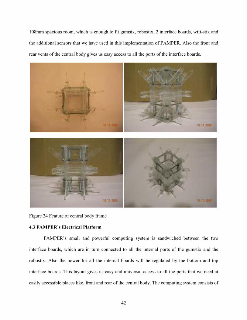
42
108mm spacious room, which is enough to fit gumsix, robostix, 2 interface boards, wifi-stix and
the additional sensors that we have used in this implementation of FAMPER. Also the front and
rear vents of the central body gives us easy access to all the ports of the interface boards.
Figure 24 Feature of central body frame
4.3 FAMPER’s Electrical Platform
FAMPER’s small and powerful computing system is sandwiched between the two
interface boards, which are in turn connected to all the internal ports of the gumstix and the
robostix. Also the power for all the internal boards will be regulated by the bottom and top
interface boards. This layout gives us easy and universal access to all the ports that we need at
easily accessible places like, front and rear of the central body. The computing system consists of

43
a stack of 5 boards, which are bottom interface board, Robostix, Gumstix, Wifi-stix and top
interface board from bottom to top respectively.
Figure 25 FAMPER's electrical disassembly
4.4 Electronic Architecture
FAMPER has been implemented with a RF-CCD Camera which can send the video
stream independently without any intervention from other modules implemented. The sensors
that are included in this particular implementation of FAMPER are 3D-Accelerometer, Compass
and Rotary Encoder. Here, 3D accelerometer will give us the tilting information of the robot,
compass gives us the direction on which the robot is heading and rotary encoder will calculate
the distance travelled by the robot so far.
The interface board allows convenient connectivity of these sensors to the main board
and supply the required power to those modules. The Gumstix based expansion modules used in
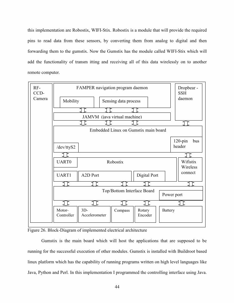
44
this implementation are Robostix, WIFI-Stix. Robostix is a module that will provide the required
pins to read data from these sensors, by converting them from analog to digital and then
forwarding them to the gumstix. Now the Gumstix has the module called WIFI-Stix which will
add the functionality of transm itting and receiving all of this data wirelessly on to another
remote computer.
Figure 26. Block-Diagram of implemented electrical architecture
Gumstix is the main board which will host the applications that are supposed to be
running for the successful execution of other modules. Gumstix is installed with Buildroot based
linux platform which has the capability of running programs written on high level languages like
Java, Python and Perl. In this implementation I programmed the controlling interface using Java.
Robostix
Embedded Linux on Gumstix main board
Wifistix Wireless
connect
Motor-Controller
3D-Accelerometer
Compass Rotary Encoder
UART1
UART0
A2D Port Digital Port
FAMPER navigation program daemon
JAMVM (java virtual machine)
/dev/ttyS2
RF-CCD-
Camera
Dropbear - SSH
daemon
Top/Bottom Interface Board
Battery
120-pin bus
header
Power port
Mobility Sensing data process

45
The sensor readings have been read using programs written in AVR-C, which are then ported to
the robostix.
4.5 FAMPER Manual Control Program
Figure 27. Feature of manual control program
In this implementation I have built a manual control interface program, which can aid us
in operating the FAMPER in most of the pipeline layouts. The interface mainly comprises of
four major panels, 3D view of FAMPER’s positions, RF video panel, which can display video
stream from the FAMPER’s RF camera, Control Panel, which gives us the ability to control the
FAMPER by using FC or even by using the GUI interface and also the tilt and direction of
FAMPER are indicated in mini 3D view, and Message Console which can display the detailed
information of the status of FAMPER.
RF Video
FC -Com Port
FC Movement
FAMPER’s tilt and direction
Message
Console
FAMPER ‘s 3D -position
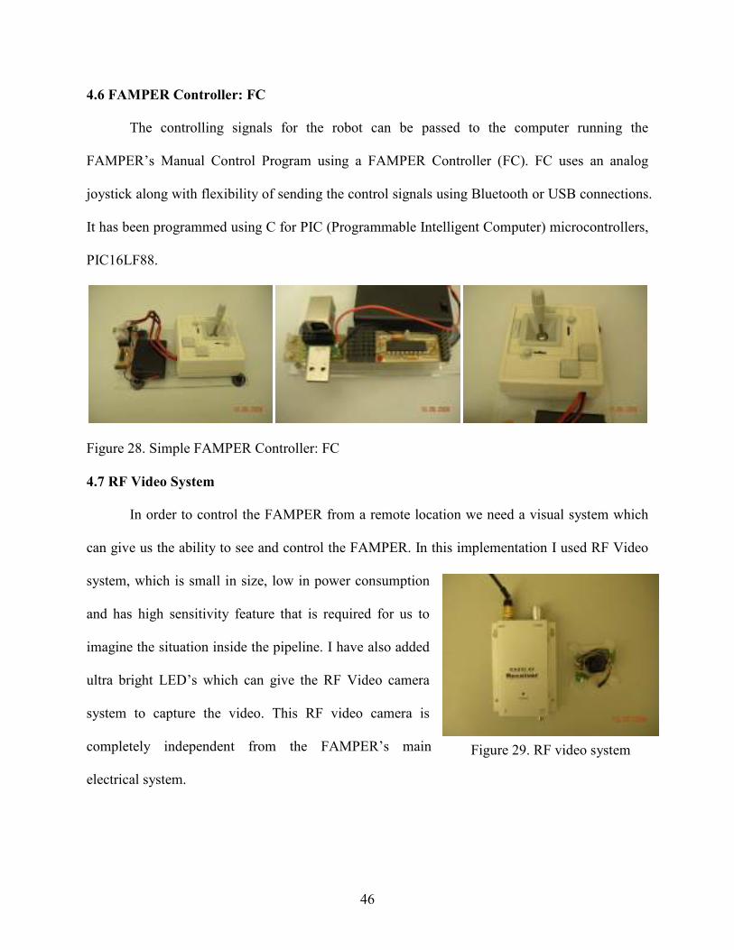
46
4.6 FAMPER Controller: FC
The controlling signals for the robot can be passed to the computer running the
FAMPER’s Manual Control Program using a FAMPER Controller (FC). FC uses an analog
joystick along with flexibility of sending the control signals using Bluetooth or USB connections.
It has been programmed using C for PIC (Programmable Intelligent Computer) microcontrollers,
PIC16LF88.
Figure 28. Simple FAMPER Controller: FC
4.7 RF Video System
In order to control the FAMPER from a remote location we need a visual system which
can give us the ability to see and control the FAMPER. In this implementation I used RF Video
system, which is small in size, low in power consumption
and has high sensitivity feature that is required for us to
imagine the situation inside the pipeline. I have also added
ultra bright LED’s which can give the RF Video camera
system to capture the video. This RF video camera is
completely independent from the FAMPER’s main
electrical system.
Figure 29. RF video system

47
5. EXPERIMENTAL EVALUATION
5.1 Elbow – 45
Figure 30. Test-bed of 45 degree elbow
As we can see from the fig.30 above, the robot starts travelling in straight pipeline and makes a
transition to a 45’ and back to the straight pipeline. Now by changing the direction of the motors
we can go backwards by following the exact path.
5.2 Elbow – 90
As we can see from the fig. 31 above, the robot starts travelling in straight pipeline and
makes a transition to a 90’ and back to the straight pipeline. Now by changing the direction of
the motors we can go backwards by following the exact path.

48
Figure 31. Test-bed of 90 degree elbow
5.3 Branch T
As we can see from the fig. 32 above, the robot starts travelling in straight pipeline and
makes a transition to right of a T branch, in the similar fashion as it would for a 90’ turn and
back to the straight pipeline. Now by changing the direction of the motors we can go backwards
by following the exact path until the T branch, and then following the straight path ahead.
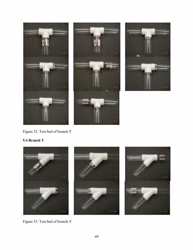
49
Figure 32. Test-bed of branch-T
5.4 Branch Y
Figure 33. Test-bed of branch-Y

50
As we can see from the fig. 33 above, the robot starts travelling in straight pipeline by
taking the path to the right of the Y-branch, and on its way back to the Y branch it moves ahead
on the straight path to meet the straight pipeline on the other end.
5.5 Complex Pipeline Layout
Figure 34. Test-bed Complex pipeline layout
The pipeline layout has been constructed using the available special fittings that a typical
pipeline layout uses. FAMPER can travel through the complete pipeline layout by changing the
motor speeds as described in Chapter 4.

51
5.6 FAMPER’s Performance Result
Table 6. Inclination angle Vs. time for 4 feet straight pipeline
I have evaluated the FAMPER’s performance in crossing a straight pipeline from one end
to the other at different inclination angles, to see how the speed would be affected with the
inclination angles. As we can see from Graph 1 quite apparently, as the inclination angle
increases from 0’ to 90’, the time taken by FAMPER to reach the other end for a downhill case,
decreases and for an uphill case, increases.
Table 7. Performance change with different elbows in 4 feet length
0 degree 15 degree 30 degree 45 degree 60 degree 75 degree 90 degree
Down 16.21 16.09 15.88 15.2 14.86 14.56 14.52
Up 16.21 16.45 17.17 17.28 18.21 18.73 18.85
121314151617181920
Tim
e /
se
c
Inclination angle Vs Time
(for 4 feet Straight pipeline)
Holizonal Down Holizonal Up Vertical Down Vertical Up
0 degree (straight) 16.84 16.84 14.32 19.06
45 degree (elbow) 20.22 20.22 19.21 20.47
90 degree (elbow) 22.37 22.37 21.21 24.66
12
14
16
18
20
22
24
26
Tim
e /
se
c
Performance changes with different elbows
52
I have compared the FAMPER’s performance in crossing different types of elbows from
one end to the other through the elbow. All the pipelines considered for this experiment are of
the same length. As we can observe from the Graph 2, the time taken for completing the trip
from one end to the other increases with the bending angle of the elbow, because, in elbows with
different bending angles FAMPER has to adjust the speed of motors in different ways as
mentioned earlier in Chapter 4, in order to successfully pass the elbow. And also we can observe
that the horizontal and vertical conditions behave in the similar way as it did for the previous
experiment.
We can conclude from the experimental results that FAMPER can effectively navigate
through most of the pipeline layouts involving both horizontal and vertical pipelines. Even when
the gravitational force, frictional force hinders the vertical movement of a robot, FAMPER was
able to successfully overcome these with minor performance changes.

53
6. DISCUSSION
Although FAMPER has been designed and developed for specific purpose, the concepts
discussed in this thesis can be extended for many other applications which require these
functionalities. And in this implementation of FAMPER, we have proved that it did accomplish
the fundamental requirements for transforming it into a fully autonomous robot, i.e. vertical and
horizontal mobility, flexible control, powerful computing system, sensitive sensors. Also we
have encountered some issues that we would like to discuss about.
6.1 Mechanics
Many robots have been designed so far in order to achieve their specific tasks. But most
of these robots are designed with a limited perspective. In other words, a robot designed by a
mechanical engineer might not consider or give much weight to the electrical and software issues
and vice versa. FAMPER has been designed in such that it could take care of the limitations
imposed for those robots. So, these issues can impose additional limitations in the design phase,
like we need to allocate enough room for the electrical compartment and also for the mechanical
structure, without neglecting the overall size specifications. We have encountered one such
problem by miscalculating the length of the caterpillar links by 2 mm which in turn posed
problem navigating through Y-branches. So we can have an idea of how a difference in
millimeters can cause malfunctions in miniature sized robots. We have to decide if we need more
flexibility or more functional performance by adding Artificial intelligence to the robot, this can
be a debatable issue on whether to sacrifice flexibility or the functionality. As we are talking
about a fully autonomous robot, sacrificing the functionality could make it a failure even before
starting it, so here in the design of FAMPER we have sacrificed a little bit of flexibility to make
it a strong contender to be a fully autonomous robot, although we do not need all the
54
computational prowess that FAMPER offers in this implementation for basic navigation of a
robot.
6.2 Electronics
Power is one of the main issues which could limit the ability to use the robots in many
applications. FAMPER is designed to run on 4 batteries, which are the only source of power for
the entire robot, both the mechanical and electrical devices. Most of the power from the batteries
is used for the operation of the motors and the rest for the computational devices. So, one of the
core challenges that we should be taking care of in the future implementations is to make
FAMPER intelligent enough to avoid taking the paths which are already explored, so in a way
we will be saving the power for exploring the unexplored paths of the pipeline. From the
experiments conducted using the present implementation of FAMPER, we have observed that
motors consume about 75-80 % of the power from the batteries, so we can be aware of how
important it is to regulate this to an efficient level.
6.3 FAMPER System Programming
As we mentioned previously we need a good Artificial intelligence system to make the
robot both efficient in performance and the overall power consumption. So far many different
algorithms have been proposed in normal field operations such as Unmanaged Autonomous
Vehicle, Unmanned Aerial Vehicle, etc. These algorithms can be extended to the pipeline
situations, but might not be as efficient as they were for the designed purposes. This leaves us an
opportunity to develop new artificial intelligence algorithms for pipeline structures. We have
also considered of implementing multiple robots, so that they can do the given job in co-
ordination with each other robots. This will help us save the time taken to complete the given
mission. The multi-robot strategy can also be used in rescuing other robots in certain conditions

55
which we will be discussing shortly. Also we need to add the required functionality in order for
the robot to get back to the dock or a predetermined location in case of low power conditions,
which will basically help it in not creating problems while trying to solve them.
6.4 Environmental Concerns
When working with real world pipeline structures, the inner pipeline conditions could be
uncertain to the robot, such as residual water in the pipelines, disfigured pipelines, etc. Especially
water could cause unrecoverable damage to the robot if it is not protected from the same. So we
have to consider this issue by making electrical compartment waterproof. FAMPER has been
designed to have a homogenous electrical body that could be enclosed into a waterproof capsule
with minor changes. Also malfunctioned or damaged robot could hinder the operation of the
pipeline by obstructing the path; we can clear this path with the help of other autonomous robots
similar to the way the rescue team save the subject in trouble.
So in order satisfy all these limitations we need to come up with a truly efficient
algorithms to take care of the same. Thus we can confidently propose that these could provide
the required springboard to FAMPER, in order to take its first plunge as a fully autonomously
mobile robot.

56
7. CONCLUSION
Robots have been used in many areas to replace the human efforts. Specially, pipeline
maintenance is challenging area for which robots can be employed. Many robots have been
developed for various pipeline based applications. There are sound ways to inspect pipelines; In-
pipe inspection is one of them, on which I have focused my research. This thesis pays attention
to the concept and design of mobile autonomous robot to explore pipelines by browsing them. A
fully autonomous mobile pipeline inspection robot should have five principle features; firstly
good mobility in the pipeline network is a must, secondly good sensing ability for pipeline
inspection, thirdly good artificial intelligence for autonomous navigation, fourthly powerful
computing system for processing large sensed data and sophisticated control and lastly powerful
battery to increase its potential mission range. In this thesis, I propose design of a fully
autonomous mobile pipeline inspection robot, named FAMPER. I have also described the
mechanism that FAMPER provides for excellent mobility in vertical as well as horizontal
pipelines, and proposed the system architecture that would enable FAMPER to be fully
autonomous. In this implementation, FAMPER is equipped with a small yet powerful computing
system, which allows it to be capable enough to execute complicated artificial intelligence
algorithms. In addition, it has easy and extendable interfaces for various sensors. In the
experiments, FAMPER showed excellent mobility in 6 inch sewer pipeline layout using its wide
caterpillar tracks, independent flexible links and thanks to the sophisticated control mechanism.
During evaluation, certain limitations in control of FAMPER while navigating through T
and Y branches were found. But it is a minor implementation problem, which can be easily
remedied by making simple modifications to the caterpillar track. The main challenge that we
could be facing is to completely implement the mentioned operational architecture of FAMPER,
57
to make it fully autonomous robot. Also we have to consider the pipeline inspection
methodology which can increase the FAMPER’s application areas.

58
REFERENCES
[1]” PIGGING: Increasing Appreciation Of An Industry Truly Come Of Age”, staff report in Pipeline & Gas Journal – p.48 ~ 51 /August 2002/pipelineandgasjournalonline.com [2] S. Hirose, H. Ohno, T. Mitsui, and K. Suyama, “Design of in-pipe inspection vehicles for -25, -50, -150 pipes,” in Proc. IEEE Int. Conf. Robotics, Automation, 1999, pp. 2309–2314. [3] Kawaguchi, Y.; Yoshida, I.; Kurumatani, H.; Kikuta, T.; Yamada, Y.,” Internal pipe inspection robot” Robotics and Automation, 1995. Proceedings., 1995 IEEE International Conference on Volume 1, 21-27 May 1995 Page(s):857 - 862 vol.1 [4] Suzumori, K.; Miyagawa, T.; Kimura, M.; Hasegawa, Y., “Micro inspection robot for 1-in pipes“ ,Mechatronics, IEEE/ASME Transactions on Volume 4, Issue 3, Sept. 1999 Page(s):286 [5] Se-gon Roh; Hyouk Ryeol Choi , “Differential-drive in-pipe robot for moving inside urban gas pipelines” Robotics, IEEE Transactions on [see also Robotics and Automation, IEEE Transactions on] Volume 21, Issue 1, Feb 2005 Page(s):1 – 17 [6] Roman, H.T.; Pellegrino, B.A.; Sigrist, W.R., “Pipe crawling inspection robots: an overview”, Energy Conversion, IEEE Transaction on Volume 8, Issue 3, Sept. 1993 Page(s):576 – 583 [7] Ryew, S.M.; Baik, S.H.; Ryu, S.W.; Jung, K.M.; Roh, S.G.; Choi, H.R., “In-pipe inspection robot system with active steering mechanism” , Intelligent Robots and Systems, 2000. (IROS 2000). Proceedings. 2000 IEEE/RSJ International Conference on Volume 3, 31 Oct.-5 Nov. 2000 Page(s):1652 - 1657 vol.3 [8] Neubauer, W.,” A spider-like robot that climbs vertically in ducts or pipes”, Intelligent Robots and Systems '94. 'Advanced Robotic Systems and the Real World', IROS '94. Proceedings of the IEEE/RSJ/GI International Conference on Volume 2, 12-16 Sept. 1994 Page(s):1178 - 1185 vol.2 [9] Pfeiffer, F.; Rossmann, Th.; Loffler, K., “Control of a tube crawling machine”, Control of Oscillations and Chaos, 2000. Proceedings. 2000 2nd International Conference Volume 3, 5-7 July 2000 Page(s):586 - 591 vol.3 [10] Bertetto, A.M.; Ruggiu, M., “In-pipe inch-worm pneumatic flexible robot” , Advanced Intelligent Mechatronics, 2001. Proceedings. 2001 IEEE/ASME International Conference on Volume 2, 8-12 July 2001 Page(s):1226 - 1231 vol.2 [11] Menciassi, A.; Park, J.H.; Lee, S.; Gorini, S.; Dario, P.; Jong-Oh Park, “Robotic solutions and mechanisms for a semi-autonomous endoscope “, Intelligent Robots and System, 2002. IEEE/RSJ International Conference on Volume 2, 30 Sept.-5 Oct. 2002 Page(s):1379 - 1384 vol.2 [12] Hayashi, I.; Iwatuki, N., “Micro moving robotics”, Micromechatronics and Human Science,

59
1998. MHS '98. Proceedings of the 1998 International Symposium on 25-28 Nov. 1998 Page(s):41 – 50 [13] Ilg, W.; Berns, K.; Cordes, S.; Eberl, M.; Dillmann, R., “A wheeled multijoint robot for autonomous sewer inspection “, Intelligent Robots and Systems, 1997. IROS '97., Proceedings of the 1997 IEEE/RSJ International Conference on Volume 3, 7-11 Sept. 1997 Page(s):1687 - 1693 vol.3 [14] Kirkham R, Kearney P, Rogers K, Mashford J. 2000. PIRAT - A System for Quantitative Sewer Pipe Assessment. In: International Journal of Robotics Research. 19(11): 1033-1053. [15] implementation of PIRAT - http://www.csiro.au/solutions/pswg.html [16] R.Bradbeer., “The Pearl Rover underwater inspection robot”, In Mechatronics and Machine vision, J.Billingsley (ed), Research Studies Press, UK, pp. 255–262, 2000. [17]Hustadt, U.; Dixon, C.; Schmidt, R.A.; Fisher, M.; Meyer, J.-J.; van der Hoek, W., “Reasoning about agents in the KARO framework” , Temporal Representation and Reasoning, 2001. TIME 2001. Proceedings. Eighth International Symposium on 14-16 June 2001 Page(s):206 – 213 [18] Hertzberg, J.; Kirchner, F., “Landmark-based autonomous navigation in sewerage pipes”, Advanced Mobile Robot, 1996., Proceedings of the First Euromicro Workshop on 9-11 Oct. 1996 Page(s):68 – 73 [19] Erich Rome, Hartmut Surmann, Hermann Streich, Ulrich Licht, and Karl-Ludwig Paap, “ A Custom IR Scanner for Landmark Detection with the Autonomous Sewer Robot MAKRO” , GMD – National Research Center for Information Technology, Institute for Autonomous intelligent Systems, http://ais.gmd.de/projects/Makro/makro.html [20] Nassiraei, A.A.F.; Kawamura, Y.; Ahrary, A.; Mikuriya, Y.; Ishii, K., “Concept and Design of A Fully Autonomous Sewer Pipe Inspection Mobile Robot : KANTARO ", Robotics and Automation, 2007 IEEE International Conference on 10-14 April 2007 Page(s):136 – 143 [21] Robots Today and Tomorrow: IFR Presents the 2007 World Robotics Statistics Survey, Posted: October 29, 2007 [22] Total length of pipelines mostly based on The World Factbook, accessed in June 2008. [23] Gumstix Benchmarks , http:// www. gumstix.net/wiki/index.php?title=Benchmarks [24] Tractor L500 with Camera KS200Z, Tractor L150 w/ Camera KS150, http://www.rauschtv-usa.com/ commercial pipe-inspection robot
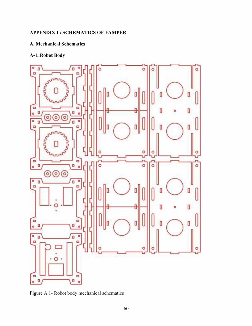
60
APPENDIX I : SCHEMATICS OF FAMPER
A. Mechanical Schematics
A-1. Robot Body
Figure A.1- Robot body mechanical schematics

61
A-2. Caterpillar Frame
Figure A.2- Caterpillar frame mechanical schematics

62
A-3. Links and Gears
Figure A.3- Link and gear mechanical schematics
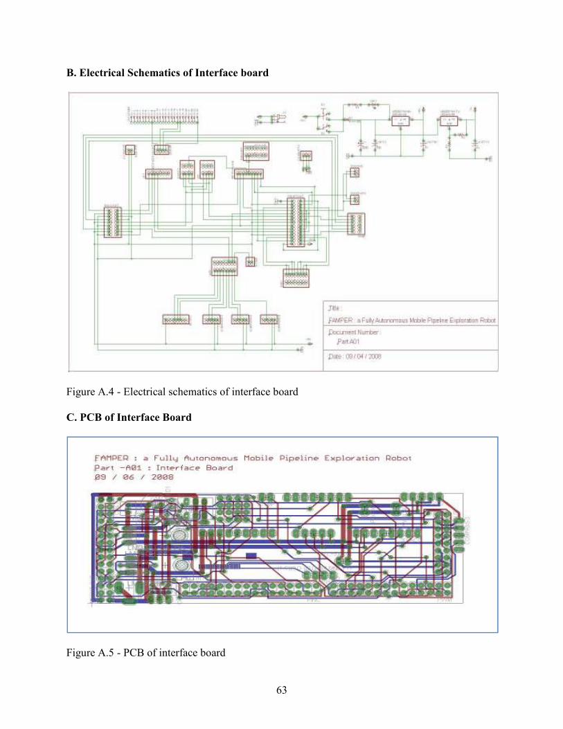
63
B. Electrical Schematics of Interface board
Figure A.4 - Electrical schematics of interface board
C. PCB of Interface Board
Figure A.5 - PCB of interface board
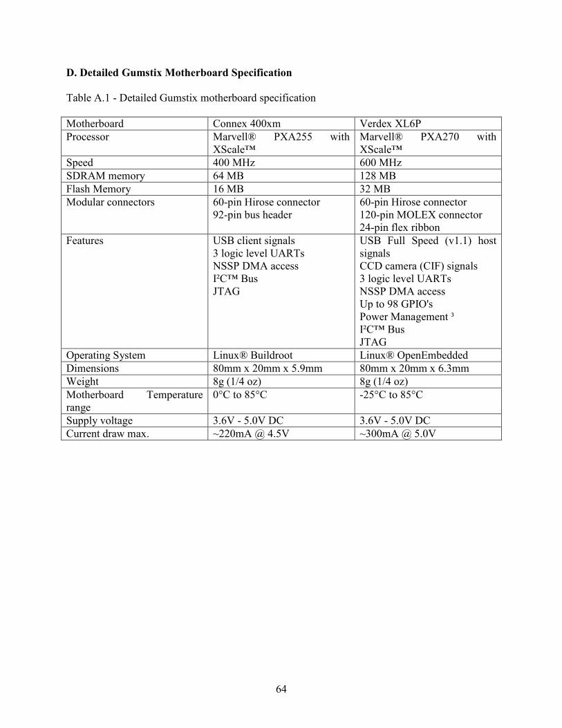
64
D. Detailed Gumstix Motherboard Specification
Table A.1 - Detailed Gumstix motherboard specification
Motherboard Connex 400xm Verdex XL6P
Processor Marvell® PXA255 with XScale™
Marvell® PXA270 with XScale™
Speed 400 MHz 600 MHz
SDRAM memory 64 MB 128 MB
Flash Memory 16 MB 32 MB
Modular connectors 60-pin Hirose connector 92-pin bus header
60-pin Hirose connector 120-pin MOLEX connector 24-pin flex ribbon
Features USB client signals 3 logic level UARTs NSSP DMA access I²C™ Bus JTAG
USB Full Speed (v1.1) host signals CCD camera (CIF) signals 3 logic level UARTs NSSP DMA access Up to 98 GPIO's Power Management ³ I²C™ Bus JTAG
Operating System Linux® Buildroot Linux® OpenEmbedded
Dimensions 80mm x 20mm x 5.9mm 80mm x 20mm x 6.3mm
Weight 8g (1/4 oz) 8g (1/4 oz)
Motherboard Temperature range
0°C to 85°C -25°C to 85°C
Supply voltage 3.6V - 5.0V DC 3.6V - 5.0V DC
Current draw max. ~220mA @ 4.5V ~300mA @ 5.0V

65
APPENDIX II : GUMSTIX AND ROBOSTIX BASICS
A. Gumstix Basics
Gumstix is entirely based on the software framework called Open Embedded or Buildroot,
which are the forms of Linux frameworks for embedded architectures. We can cross compile the
packages needed for the project and port them to Gumstix using Serial interface, USB, MMC,
Ethernet or Wireless mediums. Also the base Linux open embedded image needs to be built on a
regular computer (with Linux preferred) by bitbaking the required recipe, which can be found at
http://www.gumstix.net. The earlier way of building the Linux image for the Gumstix was done
using Buildroot method of building images, which uses make files instead of bitbake recipes in
the case of the more recently adapted procedure of building Linux images for Gumstix’s.
Figure B.1 - Front and back view of Gumstix
As you might be wondering on how the packages compiled on one architecture work on
an entirely different architecture. They won’t work if we have compiled the packages for that
particular machines architecture, then we should be using a compiler called avr-gcc which is a
gcc compiler for AVR architecture based chips. Thus, we could be sure that the packages will be
compiled for AVR architecture. So as we will be using the avr-gcc to compile the packages, we
can just transfer the binaries to the Gumstix by packaging all the binaries together. We will not

66
have the complete libraries on the Gumstix as we have minimal flash memory on the Gumstix.
As even with the most recent Verdex based Gumstix motherboard, we will only have a flash of
about 32 MB.
The basic process outline of getting a Gumstix to work for our needs can be outlined as,
obtaining a buildroot, creating filesystem image, recompile the Linux kernel, replacing the
filesystem image, cross-compiling any other required packages and transferring the binaries onto
the Gumstix.
We will discuss the procedures of building the Linux image for the Gumstix as some of
the packages that we need to compile for the Gumstix may not come with the bitbake recipe. In
such a case we can still compile the package using the traditional makefile compilation
procedure. Let us see how we can setup the environment needed for building the Linux image for
Gumstix using either Buildroot procedure or the Open Embedded (bitbake based) procedure. We
have used Ubuntu (Debian based Linux Distribution) as the base platform for setting up the
Buildroot as well as open embedded environment.
After setting up the basic Ubuntu installation, we need to install some basic packages so
that we will be able to get the flash filesystem image using Buildroot procedure. The packages
required are, autoconf, automake, libtool etc. All of these packages, which are essential for
setting up the build environment, can be installed using a single package in Ubuntu called build-
essentials. Now we need some more packages depending on the way we would like to setup the
flash filesystem image. For a person who prefers much like a graphical interface, we might also
need to install a package called ncurses, which is provided as libncurses, libncurses-dev in
Ubuntu. In addition we also need packages like bison, flex, texinfo, and set of utilities which will

67
provide the framework for generating multi-lingual messages; also some libraries which are used
by these packages. All of these can be installed a single command in Ubuntu.
sudo apt-get install build-essential libncurses-dev bison flex texinfo zlib1g-dev gettext openssl-
dev autoconf
Once we install all of the above packages, we then have to build environment setup. Now
we need to check out the Buildroot packages from the Gumstix repository using svn and wget.
Thus, in order to use them we need install subversion and wget on the machine, which can be
done as,
sudo apt-get install subversion wget
And also once we have our flash filesystem image built, we need some kind of interface
which will basically allow us to transfer files to the Gumstix and see what’s happening with the
Gumstix. In order to do so, we need some more packages like tftpd, kermit or minicom and lrzsz
(serial z-modem drivers). We can install them as,
sudo apt-get install ckermit tftpd-hpa lrzsz
Finally we have completed setting up the basic environment needed for building the basic
flash filesystem image. Now we are ready to check out the buildroot packages from the Gumstix
repository.
svn co -rXXX http://svn.gumstix.com/gumstix-buildroot/trunk gumstix-buildroot
Here, XXX denotes the release number of the Buildroot which we would like to check
out. So far, we have found out that versions 1161, 1541 and 1588 are the stables ones. So we can
check out one of these releases. The more recent the release is, the more recent the kernel version
is. So we might need to make sure all the packages that we will need for the setup of the Gumstix
are indeed supported for that particular kernel version. Once we check out the Buildroot package

68
from the Gumstix repository, we can start the compilation by first creating the configuration file,
which will indeed tell the makefile how to compile the packages and what to compile.
cd gumstix-buildroot
rm .config
make defconfig
make
Here we get into the gumstix-buildroot folder which we checked out using svn, remove
any pre-existing configuration file (if exists) and then make the default configuration file with
the filename .config. Now once we get the .config file we can open this file using any text editor
and edit the file by commenting out the packages which we do not need, and by un-commenting
the packages which we need. If you think we need a better looking interface for editing
the .config file, we can do,
make menuconfig
The menuconfig argument to the make command will give us a curses based interface for
editing .config file. Once we have completed the making the configuration file, we can issue the
make command to compile all the selected packages and make flash filesystem image. Once the
flash filesystem image has been successfully built, we can find the image file with .jffs2
extension.
In order to use the latest flash file system image which we have built using the Buildroot
package, we need to deploy that image onto the Gumstix. The flash image can be found in the
gumstix-buildroot directory, which we checked out from the Gumstix repository and started the
compilation in. Along with the rootfs.arm_nofpu.jffs2 file we can also find a couple of more files
named uImage and u-boot.bin file. If you notice the directory structure of which the image was

69
made (Directory structure can be found under $GUMROOT/build_arm_nofpu/root/), you can see
that the /boot directory is missing in that structure. The boot directory has been packaged as
another image uImage, and u-boot.bin is the boot-loader file which tells the Gumstix where to
look for the newly installed file system image.
For transferring the images which we have built till now, we need to connect the Gumstix
to the computer which has those images using kermit or minicom. We will be using the serial
connection to connect the Gumstix to the computer, so we can launch the kermit as,
kermit -l /dev/ttyS0
Here ttyS0 is the name given for the serial port on the Linux machine. Once we get
connected to /dev/ttyS0, in order to listen to the Gumstix, we need to set the parameters on the
kermit as required by the Gumstix.
set carrier-watch off
set reliable
fast
set prefixing all
set file type bin
set rec pack 4096
set send pack 4096
set window 5
set modem type none
set flow-control none
Some of these parameters need to be set only if we are transferring files to the Gumstix
(rec pack, send pack, window, modem type) as we are now. Once we set these parameters on the

70
kermit, we can simply start listening by typing 'connect' on kermit prompt. We can then start
spewing out the output from the Gumstix, and stop at the login prompt. We can login to the
Gumstix using the user name 'root' and the password 'gumstix'. The reason we are able to login is
because the Gumstix is pre-installed with Linux from the factory. In order to change the file
system image we need to stop the Gumstix at the boot-loader prompt 'GUM>'. We can do that by
hitting any key while the Gumstix is starting and gives us a timeout of 3 seconds to get into the
bootloader. Once we are at the boot-loader prompt we can start the transfer by issuing these
series of commands.
GUM>loadb a2000000
kermit>send rootfs.arm_nofpu.jffs2
kermit>connect
GUM>pro on 1:0-1 && jera all && cp.b a2000000 40000 ${filesize}
Initially by loadb we are asking the Gumstix to load whatever comes next has to be
received in binary mode at the given address. Then we go back to the kermit (by holding Ctrl +
\ and c) and send the root file system image. Once we are done sending the file we connect back
to the Gumstix and copy the image to the right location. And, we can transfer the uImage file in
the similar fashion,
GUM>loadb a2000000
kermit>send uImage
kermit>connect
GUM>katinstall 100000
GUM>katload 100000
GUM>bootm
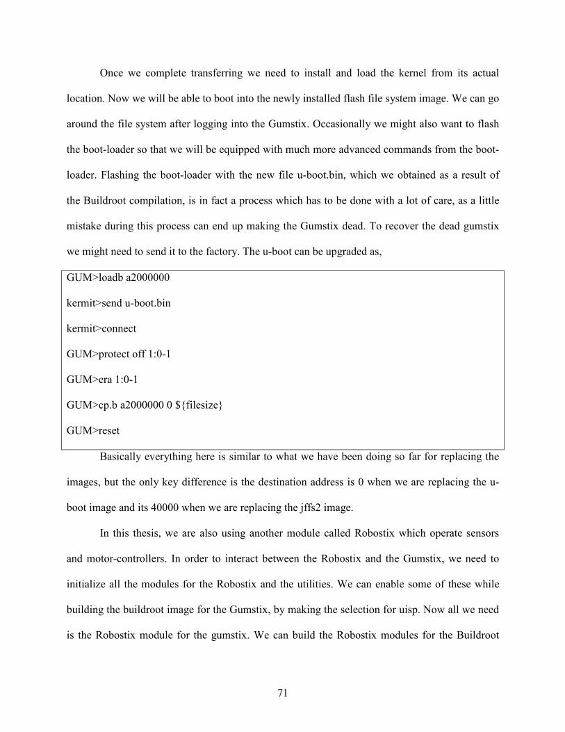
71
Once we complete transferring we need to install and load the kernel from its actual
location. Now we will be able to boot into the newly installed flash file system image. We can go
around the file system after logging into the Gumstix. Occasionally we might also want to flash
the boot-loader so that we will be equipped with much more advanced commands from the boot-
loader. Flashing the boot-loader with the new file u-boot.bin, which we obtained as a result of
the Buildroot compilation, is in fact a process which has to be done with a lot of care, as a little
mistake during this process can end up making the Gumstix dead. To recover the dead gumstix
we might need to send it to the factory. The u-boot can be upgraded as,
GUM>loadb a2000000
kermit>send u-boot.bin
kermit>connect
GUM>protect off 1:0-1
GUM>era 1:0-1
GUM>cp.b a2000000 0 ${filesize}
GUM>reset
Basically everything here is similar to what we have been doing so far for replacing the
images, but the only key difference is the destination address is 0 when we are replacing the u-
boot image and its 40000 when we are replacing the jffs2 image.
In this thesis, we are also using another module called Robostix which operate sensors
and motor-controllers. In order to interact between the Robostix and the Gumstix, we need to
initialize all the modules for the Robostix and the utilities. We can enable some of these while
building the buildroot image for the Gumstix, by making the selection for uisp. Now all we need
is the Robostix module for the gumstix. We can build the Robostix modules for the Buildroot

72
version as,
cd (to the directory containing gumstix-buildroot)
svn co -rXXX http://svn.gumstix.com/gumstix-buildroot/branches/projects/robostix robostix
cd robostix/gumstix
make
Here it is important that we check out the Robostix repository in parallel to the Gumstix
repository, in other words, both the gumstix-buildroot directory and the robostix directory in the
same parent directory. Once we complete the compilation successfully, we can find the Robostix
module as robostix_drv.ko. We need to copy all the essential files like, robostix_drv.ko, robostix,
sertest onto the Gumstix. When we have these files on the Gumstix, we can insert the Robostix
module by issuing the command,
insmod robostix_drv.ko (if this file is in the present working directory)
lsmod
Once we insert the module we can check if the Gumstix is recognizing the Robostix by
issuing the command uisp, which will if everything is done successfully, acknowledge by saying
“ATMega 128 found”.
B. Robostix Basics
Robostix is one of the expansion modules that is designed to accompany the Gumstix in
applications. Robostix comes with an AVR ATmega 128 micro controller with the capability of
converting analog to digital, digital to digital, and pulse width modulation. It has 8 ADC (Analog
to Digital Converter) channels which will make it an eligible choice for this implementation of
FAMPER. The Robostix board also consists of I/O pins that can be used to control any of the
external sensors connected to them or modules that we might connect to the Robostix. For

73
instance we can connect additional LED's to the I/O pins of the Robostix and make them to
dictate the status of the robot. Robostix can run the code as a standalone micro controller, but it
has a very slower processor and smaller memory than the Gumstix. In order to use the sensor
values in the Gumstix, we need to connect the Gumstix to the Robostix. Hence we can clearly
say that Robostix will add much more flexibility to the Gumstix in every way.
Figure 1 Front and Rear view of Robostix
As of now the Gumstix does not ship with the ability of converting analog to digital, but
we can use Robostix which is included with an analog to digital converter and grab the digital
outputs. Robostix inherits this ADC functionality from its AVR Atmega 128 micro controller.
The Gumstix and the Robostix are connected together using serial port also called, STUART
(/dev/ttyS2) and UART0, in other words the serial port STUART on Gumstix is connected to the
UART0 serial port of Robostix in such a way that the Tx port of the Gumstix connected to the
Rx port of the Robostix and the Rx port of the Gumstix connected to the Tx port of Robostix.
Now as the Gumstix is now successfully connected to the Robostix we can use programs like
uisp, which allows you to program the AVR Atmega 128 micro controller through the serial
ports of the Gumstix and Robostix.

74
Table B.1 - UART
Function Pin Pin Function
STUART RxD (GPIO 46) 1 2 Gnd
+5 3 4 robostix UART-0 TxD (Port E.1)
STUART TxD (GPIO 47) 5 6 +5
Gnd 7 8 robostix UART-0 RxD (Port E.0)
robostix UART-1 RxD (Port D.2) 9 10 Gnd
+5 11 12 I2C SDA (Port D.1) labelled TX
robostix UART-1 TxD (Port D.3) 13 14 +5
Gnd 15 16 I2C SCL (Port D.0) labelled RX
Table B.2 -. Analog to digital (A/D)
Pin Label GPIO JTAG
1 AD0 Port F.0
2 AD1 Port F.1
3 AD2 Port F.2
4 AD3 Port F.3
5 AD4 Port F.4 TCK
6 AD5 Port F.5 TMS
7 AD6 Port F.6 TDO
8 AD7 Port F.7 TDI
The communication protocol on the Robostix waits for any incoming ASCII characters
on UART0, that would represent ADC channel numbers from 0 to 7, and then responds with the
current voltage value on that particular ADC channel, in hexadecimal format encoded as ASCII

75
string. As we have a little bit of basics on how the Robostix works and all, we can start and learn
on how to flash new programs onto the Robostix.
Table B.3 - PortC of Robostix
Pin Label GPIO
1 PC0 Port C.0
2 PC1 Port C.1
3 PC2 Port C.2
4 PC3 Port C.3
5 PC4 Port C.4
6 PC5 Port C.5
7 PC6 Port C.6
8 PC7 Port C.7
We can compile the program that we have made for the Robostix using a makefile that
will generate the hex file for flashing the Robostix. Once we have the required hex file on our
machine, we can connect to the Gumstix and insert the Robostix module so that the Gumstix
could see the Robostix.
insmod robostix_drv.ko
lsmod
Once the Robostix module is inserted, we can start the application uisp by using the command,
# uisp
AVR ATMega 128 Found
if the uisp program does not acknowledge with the AVR ATMega found message, you might
need to check if you have the connected the Rx port of the STUART to Tx of UART0 and Tx of
76
STUART to Rx of UART0. Now once we get the acknowledgment, we need to set the fuses on
the Robostix. We can do that by,
uisp --wr_fuse_l=0xbf --wr_fuse_h=0xc9 --wr_fuse_e=0xff
Now the Robostix is ready to accept the flash file for the micro controller. We can send the hex
file to the Robostix using the command,
uisp --erase --upload if=Motor.hex
With the added capabilities of Robostix on Gumstix, the FAMPER's architecture will
certainly give the ability of being a Fully Autonomous Mobile robot.

77
VITA
Jong-Hoon Kim was born in Jeongseon, South Korea, in November 1972. He graduated
Jaedong Elementary School in Seoul, South Korea, followed by Choongang Middle School in
the same city. Next, he graduated Jeongseon High School in Jeongseon, South Korea, in
February 1991. He served in Korean Amy for twenty seven months. In February 1996, he earned
a college diploma from department of legal studies at KyungBuk College, South Korea. He was
employed as a system administrator for NICES project in IBM-Korea from April 2000 to
February 2002. He worked as a system supervising manager in I-BUS from March 2002 to
September 2004. During his tenure at I-BUS, he earned a Bachelor of Engineering in Seoul
National University of Technology in Seoul, South Korea, 2005. Further, he began his studies at
Louisiana State University in August of 2005. JongHoon Kim will receive the degree of Master
of Science in System Science in December 2008.


![[ICIT-2010] FAMPER - a Fully Autonomous Mobile Robot for Pipeline Exploration](https://img.pdfslide.net/doc/110x75/55cf988e550346d033985323/icit-2010-famper-a-fully-autonomous-mobile-robot-for-pipeline-exploration.jpg)