Embed Size (px)
Citation preview


AT 151Megahy, James A.Design of a reinforcedconcrete arch


Design of a R&lnfofced Ooncreije Af©h
A THESD.PRESENTED BY ..
^^ ^..TO THE...
PRESIDENT ^ND FACULTYOF THE
ARMOUR INSTITUTE OF TECHNOLOGYFOR THE DEGPIEE OF
Bachelor of Science in Civil Engineering
Having Completed the Prescribed Course of Study in Civil
ENGINEERING
APRIL 1ST 1909 ^
ILLINOIS INSTITUTE OF TECHNOLOGY
PAUL V.GALVIN LIBRARY
35 WEST 33RD STREET
CHICAGO, IL 60616
<^^ti^
^^ ^J-eji4^ Y^t^^^- ^^^a^c/^


•' THESIS."
" THE DESIGN CF A REINFORCED CCNCR^ITE ARCH
OF 80 SPAil."
The arch is to have a total width of 38ft • , 22 ft* for road-
way and two 8 foot cement sidewalks • The live load is to 'oe 10*-' lbs
per sq» ft« and provision is to "be made for street car traffic.
LOA DING:- The car track occupies a width of 16 2/3 ft • and tlie live
load T>er linear foot of track 1300 p er sq»ft. Remaining floor
surface 160 lbs ver sq.ft« including sidewalks*
DEAD LOAD:- Concrete 150 lbs per cu«ft»Hlarth fill 120 • ^Pavement 12''deep 150 lbs per cu.ft*Car track 25 lbs per sq.ft*
//
LIVE LOAD:- 1800 lbs per linear ft. of bridge over 16 2/3 width100 " "sq.ft* for remainder of floor surfac e»
" METHOD OF DESIGN."
The method used is that of Prof« Cain, with the construction of the
deflection polygons from Prof* Burr's "i^tresses in Bridge and Roof
Trusses." The methos of finding the summations by tabulation is due
to Mr* Thacher. In the design of an arch, the rr.ethod consists in
finding the true equilibrium polygon for any system of loading and
its true position in the arch ring. The conditions which, when
fulfilled, give the results are (I) that the ^tangen+r^ ^^ ^^^ neutral
line of the ring at the springing are fixed in direction (2) that
the span is invariable; and (3) that the vertical deflection of one
springing line with respect to the other is zero*
Expressed mathematically, these conditions are;
FT '
^ EX - '

I
- 2 -
m »hict, (s) 13 the le,^th of a 3„an division of seg,„e„t of th,rins measured on the neutral line and (y) and (x) are, reer ectiveiy
,
the ordinate and absiasa of the center of (a) with the origin at one'
Bprinsln^; Por a reinforoed concrete ring theae equations of condl-tion take the form
Let H ^horizontal thrust, which is constant throughout the ring forany ^iven loading.
,the intercept of the ordinate between the neutral axis and the line .
of pressure.
M.Ht, and ^.E^<, practically constant thro^hcUhen,/ we make 3^t^^.„„.Wb,c.«^^,„J^---^rnayhe placed outside of the sign of summation and we have , I
Zt^o . Xty= o . and ZtK - o'
l.^lsi^ constant throughout the ring, therefore making Sfleconstantfulfills the condition.
smoe I^b'h-^12, Where (o') Is the tnlcknesa of the slice of the ringconalderod. usually 12 inches and (h) ia the radial depth of the ringwe r.&y construct s^-tf constant.
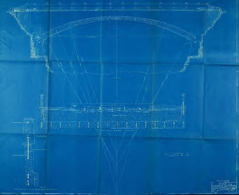
iSir^.ris* (^) was made. V8 of the span or lo feet-The radius of the center line.(R), ,,HfiL4-4) where L is the le.^th ofthe spsm. ^^
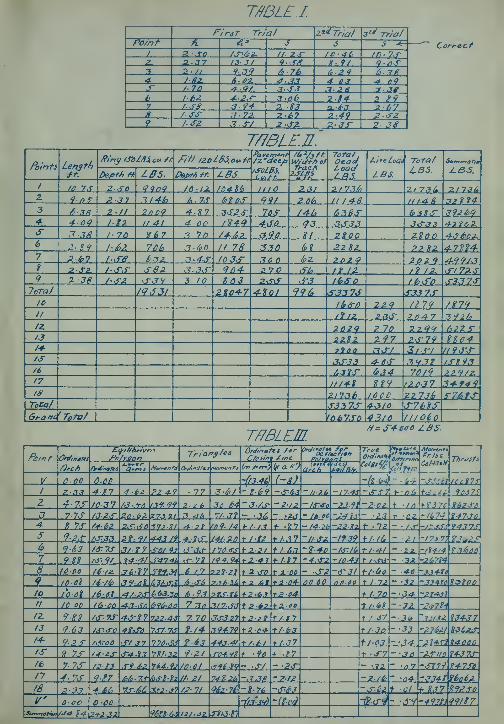
The ring was propotioned and subdivided into 18 segments ^^^so as tomake .^^j3con8tant. The Bracing is shown in table I . The loads arethen commuted by table II, the live load is placed over the half spanto give benditt;^ ..
moments, maxiciuir. or nearly maxiiruEi.


- 3 -
TEIffERA.TUHE STRESSES.
Sin ce the top of the arch is covered and the underside cannot be
reached by the sun's rays, the chanfces in temperature do not affect
the arch in most cases, an appreciable amount. If temperature stress
are considered, the thrusts and bend inp- iroments °" ^"^ section can
be computed from the formula H _ Ee ^ re Xc-g-Xs where
1 - the span of the neutraA surface.c = the change of temperature of" the ring in degrees Farh.r nrate of expansion per degree Farh.m = (Jo"y )^nn=:number of divisions of the ring,"s" ;
The thrust on any section will be resultant of H perpendicular to
that section, and the bending rcomentt will be ,M=H x ( y-n^ )
.
Table IV gives the thrust and sending moments of several points
oof the ring for a change in temperature of 42 Farh.
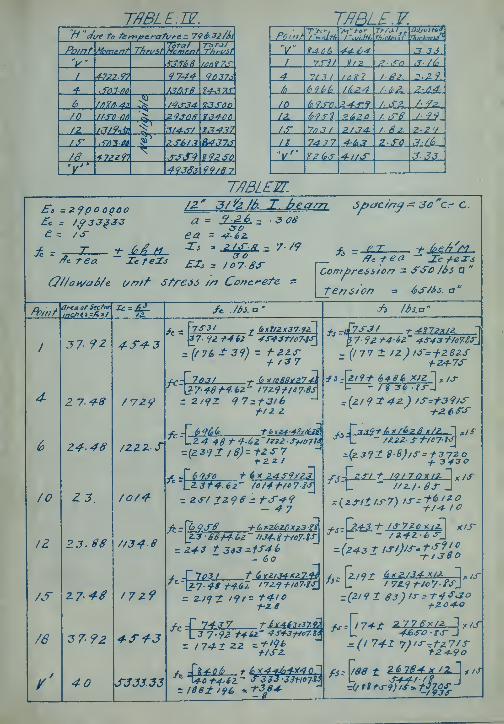
Table V gives the final stresses per sq.in* in the ring at the crit-
ical points a] 30 the assured and adjusted thicknesses. After
finding the final stresses, the intensities of the stresses in al]
parts of the concrete and of the steel reinforcement are computed
frcM.. Thaoher-, for^^^-s ii=^^t^,.„d h-^t^^^,r, ^W,ch
fc=intensity of stresses in the concrete,fj- " " " " " steel.
T^thrust on section line I wide^^, in lbs.
Ac=area of section of concrete I wide, square inches.
e= Es4Ecwhere Es=modulu3 of elasticity of steel andEc- " " " " concrete.
a - area of steel per inch width As-fb , square inches .
h.:i depth of concrete in inches. „
M=ibending moment on section 1 wide -ft lbs.
Icsrmoment t of inertia of concrete, Ac, abo ut tne neutral axis
of the com.bination.Issmoment -.0 of inertia of steel, (a), about the neutral axis
of the combination.b=distance from center to center of steel members, in the
direction of the width of the arch, inches


- 4 -
H =depth of steft] in inches*
The coirputation of the stresses in the steel and concrete are found
in taole VI •
The total heif^ht of the spandrel wall will be 12 ft* at
the springing • Supposing the earth fi31 to have an angle of repose
of 26 34 or a natural slope of 1 on 2, then the horizontal thrust
Pn wY ^ /t-^i>ii_') w = 12^0 (bs, oi> ft.
p^izoK]^^ xrilli^^T,)- 3301-25 Ib6.2 Vlt-44'7^
Bending moment ^"^ junction of spandrel wall and top of arch*
- 330l.a5 x:i^- 13^05 ftlbs.
This stress is within the allowable limits and the wall will be 10
thick at top and 13 at bottom*
SPECIFICATIONS*
These consists of the portiohof the structure indicated on the plans
and^ are either monolithic or of reinforced concrete* They embrace
providing all materials and labor to construct and complete the work
making and placing of forms, bending and placing of steel, mixing and
placing of concrete , removal of forms, removing rubbish and finish-
ing of surfaces*
FORMS: -,Tlie forms should be of such a character that after they are
removed all surfaces will be plain and level and have the proper ele-
\^atioas called for * Vi/herever a surface finish is to be used, rough
lumber can be used on that side* The size, thickness, and quality
of the lumber being left to the discretion of tne contractor. The
forms should not be removed until the concrete has become hard
- 5-
enough to sustain its own weight and the prooaole weight liacle to be
superimposed. Shores should be left in place at least four weeks.
Before concreting , all forirs should be cleaned of saw-dust, blocks
shavings, dirt and dust, holes patched with tin , oiled and sprink-
led.
CONCRETE:- The concrete is required to be mixed by volume; 1-3-6 being
required for footings and foundations and 1-2-4 for structural members
1-2 mortar for finish and this should never be less tham 1/2 inch in
thickness. Water enough to make a pasty mixture is required*
( Note - By 1-3-6 is meant 1 part cement, 3 parts sand, 6 parts by
volume of broken stone or gravel*
CEMENT:- All cement used shall be Portland cement and shall be inspec-
ted either at the place of manufacture or on the work. In order to
allow ample time for inspecting and testing, the cement shall be
stored in a suitable weather-tight building, having the floor prop-
erly blocked or raised from the ground. The ce ment shall be stored
in such a manner as to permit easy acceuo for proper inspection and
identification of each shipment. Every facility shall be provided
by the contractor and a period of at least 12 days allowed for the
inspection and necessary tests. Cement shall be delivered in suit -i
able packages with the brand and name of the manufacturer plainly
marked thereon.
A bag of cement shall contain 94 lbs of cement net. Each barrel of
Portland cement shall 4 bags of the above ^^^ weight. Cement failing
to meet the seven days requirements may be held awaiting the results
of the 28 day tests before rejection* All tests shall be made in
accordance with the methods proposed by the committee on Uniform
Tests of Cement of the American Society of Civil Engineers,


- o -
presented to the society January 21, 1903 and amended Jan. 20 1904,
with all subsequent amendments thereto* The acceptance or rejection
shall he based on the following requirements: Portland Cement:
Definition : This term is applied to the finely pulverized, product
resulting from the calcination to incipient fusion of an intimateand
mixture of properly propotioned argillaceous calcareous materials
and to which no addition greater than 3/fe has been made subsequent to
calcination*
SPECIFIC GRAVITY'.
The specific gravity of the cement thouroughly dried at 100 C shall
be not less than 3.1D*
PINETIESS.
It shall leave by weiii^ht a residae of not more than 8 /« on the Nc
100, and not more than 25/^ on the No* 200 seive*
TIME OF SETTING.
It shall develop initial set in not less than 30 minutes, but must
develop hard set in not less than one hour, nor more tnan lO hours.
TENSILE STRENGTH.
The TT'lnimum requirements for tensile strength for briq.'tettes 1 square
in section shall "be within the following limits, and shall show no
retrogression in strength within the periods specified:
NEAT CEMENT.AGE STRENGTH.24 hours in moist air 150 - 200 lbs*
7 days ( 1 day in moist air, 6 days in water) ---450 - 550 lbs*
28 days ( 1 day in moist air, 27 days in water) 550 - 650 lbs*
One part cement, three parts sand*
7 days( % day in moist air, 6 days in water) 150 - 200 lbs.
28 days ( 1 day in m.oist air, 2'? days in water) 200 - 30O lbs.

.- 7 -
CONSTANCY OF VOLJME.
Pats of neat cement about 3 diameter , 1/2 thick at the center, and
taperinp; to a thin edpe, shall be kept in moist air for a period of
24 hours, (a) a rat is then kept in air at normal temperature and ob-
served at intervals for at least 23 days . (b) Another pat is kept in
o
water maintained as near 70 F. as practicable and observed at inter-
vals for at least 23 day3« (c) A third pat is exposed in any con-
venient way in an atmosphere of steam , above boiling water , in a
loosely closed vessel for five hours* These pats, to satisfactorily
pass the requirements, shall remain firm and hard and show no signs
of distortion, checking, cracking or disintegrating.
SULPHURIC ACID AND MAGNESIA.
The cement shall not contain more than 1.7570 of anhydrons sulphuric
acid ( « not more than 4/o of magnesia ( -^u).
SAMPLING.
The sample shall be a fair average of the contents of the packafre;
edit is recommend' that, where these conditions permit , one barrel
in ev«^y 10 be sarrpjed^ All sairples shall be passed throu5;h a seive
having 20 meshes per linear inch in order to bre^ up lumps eind re-
move foreign matter; this is also a very effective method of mixing
them together in order to obtain an average. For determining the
charact^ri'stics of a shipment of cement, the individual sample may
be mixed and the avereige tested^ where time will permit , however, it
is recommended: that they be tested seperately.
METHOD OF SAMPLING.
Cement in barrels should be sampled through a hole made in the cen-
ter of one of tne staves, midway between the heads, or in the headby means of an auger or a sampling iron similar to that used by

- 3 -
sugar inspectors* If in bags, it should be taken fron surface to
center*
SAM).
All sand shall be clean sharp sand, not having any excessive amount
of foreign material in the form of loam or clay; 10 yo can be allowed.
BROKEN STOIIE.
Stone should pass a 3/4 in. ring for small work, 1 1/2 for large
work; screenings, if clean, are permitted. All stone should be free
from dirt which mufrht keep the cement from axJhering to the stone.
Sandstone/ limestone, frranite, traprock or other stone can be used.
GRAYIilL.
/•/
Gravel should be not larger than that passing a 3/4 ring and shall
contain no sand unless the portion of sand in the mixture used is
reduced. It shall also be free from clay:, loeim and other extraneous
material.
MIXING AND PLACING.
The miixmg can either be done by hand , the cement, sand and stone
being placed on a water tight mixing board, or mixed in a batch mixer
The propotion of water determined according to the nature of the
materials biing mixed ^ to give same a good, pasty, well mixed con-
sistency. The concrete shall be handled quickly and brought to the
points of placing by hoists, derricks, concrete buggies or wheel-
barrows, proper runs being supplied so that the steel may not be
displaced. No concrete that has begun to show signs of set shall
be used.
WATERPBOOFING.
The top of the arch and the sides of the spandrel walls shall be


- 9 -
//
w at erp roofed with 1/2 coating of cement mortar consisting of 1 part
cement to two parts of sand and averafre shall he provided at the
haunches by means of an unrlazed clay pipe reaching diagonally from
the center of the space over the abutment to the soffits of the arch,
through whivh it projects about an inch. The surface of tne abutment
is dished toward the upper end of the pipe, which is covered with
wire netting to exclude coarse material and a bed of broken stone
is laid over all to receive the earth fill*
SPAITDREL 7/ALL AND PARAPET WALLS.
THe spandrel wall shall be made of 1-2-4 concrete and shall be con-
nected to the cornice by para^^et walls by means of an anchor bolt 1
square and five ft« long as shown in plans.
The cornice is to be of 1-2-4 concrete and made in seven foot sections
and laid in sections like cut stone.
The parapet wall shall consist of concrete posts 8 x 12 of 1-2-4 con-
crete and shall be moulded on the bolt from the spandrel wall as
shown in plans. A hand rail of wrought iron pipe 2 internal diam-
eter shall be provided and moulded into the parapet wall. The hand
rail shall enter the smallest dimension of the posts, and to a depth
not less than four inches. All joints between the arch ring, span-
drel walls, cornice, and parapet walls, shall be filled with ce-
ment mortar of a consistency of 1-2.
RE DTFORCSMENT
.
All steel shall be medium steel, having an ultimate trnsile strength
of from 6 0,000 to 68,000 lbs per sq.in. and an elastic limit of not
less than 1/2 the ultimate strength and should elongate not less
than 22^ in 8"and bend cold 180° around a diameter equal to the

- 10 -
thicVness of the piece tested without fracture on the outside of
bend.
The I toeauns used shall "be riveted at the abutments to a 5x5x1/2
anp:le iron extending along the entire length of the abutment and
embedded therein. All reinforcement shall be not less tnan 3 in-
from the exposed surface of the concrete.
Signed '^^^^^^.^ .W^- /xT̂ ^^A^.

rmtE I.


B
Trw/ /^rch for t-he design
ofa Re.inforcec/CcncrcfeOrd,
'OurlmMtfe cf^chnr/cay


.«asafe
It


>

Sr-C '-^