Embed Size (px)
Citation preview
Abstract— This paper describes the design of composite
shock absorber mounting for an innovative rail vehicle end in which structural, crash and aerodynamic functionalities are realized in a single integrated element. An experimental activity has been conducted in order to characterize the basic stiffness and strength parameters of the selected composite material. Results of the material characterization have been used for the laminate composite material card of the FE software. The computational analysis has been performed to optimize the sandwich configuration of the composite component and to assess the structural requirements. The final configuration of the composite sandwich shock absorber mounting exhibits strength and stiffness that are very close to the existing metallic one with a significant weight saving. The activities have been performed in the context of the Italian research project “SCILLA-M” (Structures, Innovative Components, Light Applications for Metro) funded by the MIUR (Ministry of Education, University and Research).
Index Terms— Rail vehicle; shock absorber mounting; composite material; sandwich structure; lightweight design.
I. INTRODUCTION
OMPOSITE materials have been used in a wide range of applications due to their superior specific mechanical
properties over conventional materials such as metals. For example, in aerospace and automotive industries, several structures are built from composite materials in order to have high strength and stiffness to weight ratios.
Also in the railway industry composites are becoming an attractive alternative to standard metallic solution. Applications of the composite materials in railway vehicles include front cab, roof, sidewall and interior components, such as seats and paneling.
M. Grasso is with the Department of Industrial Engineering, University
of Naples Federico II, 80125 ITALY (e-mail: [email protected]). A. Genovese is with the Department of Industrial Engineering,
University of Naples Federico II, 80125 ITALY (e-mail: [email protected]).
L. Lenzi is with the Department of Carbody structures of AnsaldoBreda S.p.A., 51100 ITALY (e-mail: [email protected]).
L. Macera is with the Department of Industrial Engineering, University of Naples Federico II, 80125 ITALY (e-mail: [email protected]).
F. Penta is with the Department of Industrial Engineering, University of Naples Federico II, 80125 ITALY (e-mail: [email protected]).
G. Pucillo is with the Department of Industrial Engineering, University of Naples Federico II, 80125 ITALY (e-mail: [email protected]).
S. Strano is with the Department of Industrial Engineering, University of Naples Federico II, 80125 ITALY (corresponding author, phone: +390817683277; e-mail: [email protected]).
In [1] the manufacture of a complete vehicle bodyshell using glass and carbon fibers in a filament winding process, is presented. A mechanical characterization of a glass fiber composite/foam sandwich structure, used for the construction of the front shield of a high speed train, is presented in [2]. In [3], the manufacturing process of a composite carbody has been investigated and structural behavior has been evaluated by static load tests. A multiscale approach has been presented in [4] as optimum tool for the structural design of composite sandwich structures for a roof of railway vehicle.
The study presented in this paper is a part of a research project focusing on the design of lightweight components for a metro train produced by AnsaldoBreda.
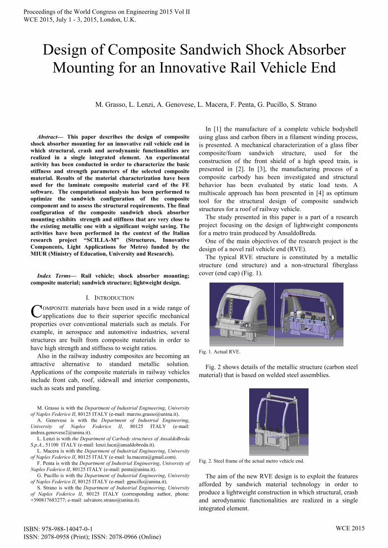
One of the main objectives of the research project is the design of a novel rail vehicle end (RVE).
The typical RVE structure is constituted by a metallic structure (end structure) and a non-structural fiberglass cover (end cap) (Fig. 1).
Fig. 1. Actual RVE.
Fig. 2 shows details of the metallic structure (carbon steel
material) that is based on welded steel assemblies.
Fig. 2. Steel frame of the actual metro vehicle end.
The aim of the new RVE design is to exploit the features
afforded by sandwich material technology in order to produce a lightweight construction in which structural, crash and aerodynamic functionalities are realized in a single integrated element.
Design of Composite Sandwich Shock Absorber Mounting for an Innovative Rail Vehicle End
M. Grasso, L. Lenzi, A. Genovese, L. Macera, F. Penta, G. Pucillo, S. Strano
C
Proceedings of the World Congress on Engineering 2015 Vol II WCE 2015, July 1 - 3, 2015, London, U.K.
ISBN: 978-988-14047-0-1 ISSN: 2078-0958 (Print); ISSN: 2078-0966 (Online)
WCE 2015
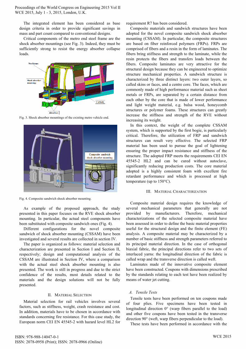
The integrated element has been considered as base design criteria in order to provide significant savings in mass and part count compared to conventional designs.
Critical components of the metro end steel frame are the shock absorber mountings (see Fig. 3). Indeed, they must be sufficiently strong to resist the energy absorber collapse loads.
Fig. 3. Shock absorber mountings of the existing metro vehicle end.
Fig. 4. Composite sandwich shock absorber mounting.
As example of the proposed approach, the study
presented in this paper focuses on the RVE shock absorber mounting. In particular, the actual steel components have been substituted with composite sandwich ones (Fig. 4).
Different configurations for the novel composite sandwich of shock absorber mounting (CSSAM) have been investigated and several results are collected in section IV.
The paper is organized as follows: material selection and characterization are presented in Section I and Section II, respectively; design and computational analysis of the CSSAM are illustrated in Section IV, where a comparison with the actual steel shock absorber mounting is also presented. The work is still in progress and due to the strict confidence of the results, most details related to the materials and the design solutions will not be fully presented.
II. MATERIAL SELECTION
Material selection for rail vehicles involves several factors, such as stiffness, weight, crash resistance and cost. In addition, materials have to be chosen in accordance with standards concerning fire resistance. For this case study, the European norm CEI EN 45545-2 with hazard level HL2 for
requirement R7 has been considered. Composite materials and sandwich structures have been
adopted for the novel composite sandwich shock absorber mounting (CSSAM). In particular, the composite structures are based on fiber reinforced polymers (FRPs). FRPs are comprised of fibers and a resin in the form of laminates. The fibers bring stiffness and strength to the laminate, while the resin protects the fibers and transfers loads between the fibers. Composite laminates are very attractive for the structural design because they can be engineered to optimize structure mechanical properties. A sandwich structure is characterized by three distinct layers: two outer layers, so called skins or faces, and a centre core. The faces, which are commonly made of high performance material such as sheet metals or FRPs, are separated by a certain distance from each other by the core that is made of lower performance and light weight material, e.g. balsa wood, honeycomb structures or polymer foams. These structures can greatly increase the stiffness and strength of the RVE without increasing its weight.
In this context, the weight of the complete CSSAM system, which is supported by the first bogie, is particularly critical. Therefore, the utilization of FRP and sandwich structures can result very effective. The selected FRP material has been used to pursue the goal of lightening ensuring the proper impact resistance and stiffness of the structure. The adopted FRP meets the requirements CEI EN 45545-2 HL2 and can be cured without autoclave, significantly reducing production costs. The core material adopted is a highly consistent foam with excellent fire retardant performance and which is processed at high temperature (up to 150°C).
III. MATERIAL CHARACTERIZATION
Composite material design requires the knowledge of
several mechanical parameters that generally are not provided by manufacturers. Therefore, mechanical characterizations of the selected composite material have been assessed in order to define the basic material properties useful for the structural design and the finite element (FE) analysis. A composite material may be characterized by a number of basic stiffness and strength parameters referred to its principal material direction. In the case of orthogonal biaxial fabric, the principal directions refer to two sets of interlaced yarns: the longitudinal direction of the fabric is called wrap and the transverse direction is called weft.
Laminates made of the innovative composite element have been constructed. Coupons with dimensions prescribed by the standards relating to each test have been realized by means of water jet cutting.
A. Tensile Tests
Tensile tests have been performed on ten coupons made of four plies. Five specimens have been tested in longitudinal direction 0° (warp fibers parallel to the load) and other five coupons have been tested in the transverse direction 90° (weft, warp fibers perpendicular to the load).
These tests have been performed in accordance with the
Proceedings of the World Congress on Engineering 2015 Vol II WCE 2015, July 1 - 3, 2015, London, U.K.
ISBN: 978-988-14047-0-1 ISSN: 2078-0958 (Print); ISSN: 2078-0966 (Online)
WCE 2015

ASTM D3039M standard [5]. Tests have been conducted at a constant cross head velocity of 2 mm/min. Figs. 5 and 6 show the stress-strain curves for both warp and weft directions, respectively.
Fig. 5. Tensile tests: stress-strain curves for warp direction.
Fig. 6. Tensile tests: stress-strain curves for weft direction.
Ultimate tensile stress and strain, elastic modulus, and
Poisson’s ratio have been measured for both the warp and weft directions.
B. Compressive Tests
Compressive tests have conducted in accordance with the ASTM D6641 standard [6]. Ten coupons, made of four plies, have been tested: five in the longitudinal direction 0° (warp) and five in the transverse direction 90° (weft). Tests have been conducted at a constant cross head velocity of 1 mm/min. Figs. 7 and 8 show the stress-strain curves for both warp and weft directions, respectively.
Fig. 7. Compressive tests: stress-strain curves for warp direction.
Fig. 8. Compressive tests: stress-strain curves for weft direction.
Ultimate tensile stress and strain and elastic modulus
have been measured for both warp and weft directions.
C. In-Plane Shear Tests
In-plane shear tests have been conducted in accordance with the ASTM D3518 standard [7]. Five coupons made of 9 plies with a [+45/-45] stacking sequence have been tested. Tests have been conducted at a constant cross head velocity of 2 mm/min.
Fig. 9 shows the shear stress-crosshead displacement curves.
Fig. 9. In-plane shear tests: shear stress-displacement curves.
Ultimate in-plane shear stress and strain and in-plane
shear modulus have been derived. The ultimate in-plane shear strain has been considered equal to 5%.
D. Interlaminar Shear Tests
Interlaminar shear tests have been performed in accordance with the ASTM D2344M standard [8]. Tests have been conducted at a constant cross head velocity of 1 mm/min. Interlaminar shear strength have been derived as function of ultimate applied load. Fig. 10 shows the interlaminar shear stress-crosshead displacement curves.
Proceedings of the World Congress on Engineering 2015 Vol II WCE 2015, July 1 - 3, 2015, London, U.K.
ISBN: 978-988-14047-0-1 ISSN: 2078-0958 (Print); ISSN: 2078-0966 (Online)
WCE 2015

Fig. 10. Interlaminar shear tests: shear stress-displacement curves.
E. Summary of Test Results
Elastic properties and strength values of the adopted FRP, obtained in static tests, are reported in Table I (mean values).
TABLE I MECHANICAL PROPERTIES OF THE FRP INVESTIGATED IN THE PRESENT
STUDY
Tensile Young Modulus Warp E1 (GPa) 58.2 Weft E2 (GPa) 57.4
Poisson’s Modulus* Warp ν12 (-) 0.07 Weft ν21 (-) 0.069
Ultimate tensile Strength Warp X1t (MPa) 906.5 Weft Y2t (MPa) 872.8
Ultimate tensile Strain Warp ε1u (%) 1.55 Weft ε2u (%) 1.77
Compressive Young Modulus Warp E1 (GPa) 54 Weft E2 (GPa) 55
Ultimate Compressive Strength Warp X1c (MPa) 734.5 Weft Y2c (MPa) 721.3
In-plane shear Modulus G12 (GPa) 4.6 Ultimate In-plane Shear Stress S (MPa) 66.8 Interlaminar shear strength -
ILSS ILSS (GPa) 39.2
*Poisson's ratio values are from literature. Mechanical properties of the foam employed as core,
declared by the manufacturer, has been reported in Table II.
TABLE II MECHANICAL PROPERTIES OF THE FOAM
Nominal Density ρ (kg/m3) 100 Compression Strength Xc (MPa) 1.36 Compression Modulus Ec (MPa) 56
Shear Strength Sc (MPa) 0.96 Shear Modulus Gc (MPa) 21
The values of Tables I and II have been implemented in
the laminate composite material card of the FE software as described in the next section.
IV. DESIGN AND COMPUTATIONAL ANALYSIS
In the present section, design and computational analysis of the CSSAM is presented. A FE model has been developed using MSC Nastran® code, starting from geometrical information of the actual metallic shock absorber mounting.
The CSSAM consists of an array of bonded foam cores wrapped in FRP in order to realize a macro-cellular structure [9]. In this structure, the core is particularly
suitable to increase flexural stiffness and to avoid the instability of FRP internal plates. The internal plates have the task to stiffen the structure and to transmit the heavy loads from the absorber.
Fig. 11 shows a scheme of the proposed solution; the adopted design variables are the number of foam core blocks (nc), the lay-up and thickness (ti) of the internal FRP and the lay-up and thickness (te) of the external FRP. Therefore, the component design optimization has been carried out by assessing the CSSAM performances, in terms of structural strength and weight reduction, varying the parameters above mentioned.
Fig. 11. Scheme of the proposed CSSAM: component and cell structure
detail.
Since the purpose of the study is to compare the new
CSSAM with the existing one, the same load condition and constraints have been set for both cases. Fig. 12 shows details of the static load case (Force = 500 kN) and the constraint configuration (translational DOFs are locked at the upper and lower edge).
Fig. 12. CSSAM static load case: load and constraints.
The FE analysis of the existing metallic shock absorber
mounting has been developed in order to have the benchmark for the design optimization of the novel CSSAM. FEM of the steel shock absorber mounting has been implemented adopting shell elements, tetra elements and a linear elastic material card.
Fig. 13 shows the results of the FE simulation in terms of displacement.
Proceedings of the World Congress on Engineering 2015 Vol II WCE 2015, July 1 - 3, 2015, London, U.K.
ISBN: 978-988-14047-0-1 ISSN: 2078-0958 (Print); ISSN: 2078-0966 (Online)
WCE 2015

Fig. 13. Steel shock absorber mounting: magnitude displacement shaped
configuration.
The maximum deflection f of the steel box (see Fig. 13
for reference) in the load direction (y-direction) has been considered as a reference parameter; its value, equal to 0.47 mm, is located in the middle of the rear plate. The overall mass of the steel box is 77 kg.
The CSSAM has been meshed using hexa elements for the foam blocks, shell elements for the FRPs and tetra element for the buffer support. Different mesh sizes for faces, core and buffer support have been used to optimize the computational time without compromising the accuracy of the results. The connection between the parts has been modeled using a glued contact with a node-to-segment algorithm. A 2D linear elastic orthotropic material card and an isotropic 3D material card have been adopted to define plies and core, respectively.
A first FE analysis (Test 1) of CSSAM has been performed with nc=4x4, ti =7 mm and te = 7 mm and the same ten plies lay-up [0/90; 0/90; ±45; ±45; 0/90]s for all FRPs. The displacement map for Test 1 is shown in Fig. 14.
Fig. 14. CSSAM shaped configuration for Test 1; a) Displacement magnitude; b) Deflection in y-direction.
The maximum rear deflection of CSSAM for Test 1 is f=0.91 mm.
The Tsai-Wu failure criteria has been assumed to evaluate the CSSAM strength in terms of ply stress and interlaminar shear stress. The maximum Failure Index (FI) map for Test 1 is reported in Fig. 15.
As shown in Fig. 15, the CSSAM in Test 1 configuration has adequate strength, indeed values of FI are less than one for all the elements. In terms of stiffness, the value of f is 94% greater than the one referred to the steel box.
Fig. 15. CSSAM shaped configuration for Test 1: Tsai-Wu Failure Index.
Several simulations have been performed in order to
investigate the effect of the design variables on the CSSAM performances. Starting from nominal dimensions, the weight of each configuration has been theoretically evaluated. The weight of the composite plates has been estimated determining the equivalent density by means of the mixture rule. Results of all the simulations, in terms of f and CSSAM weight (W), are collected in Table III. Details of lay-up sequences for all the tests are reported in Table IV.
TABLE III FE ANALYSIS RESULTS FOR DIFFERENT CSSAM CONFIGURATIONS
Test case nc f
(mm) Δf %
W (kg)
ΔW %
Steel shock absorber mounting (reference)
- 0.470 - 77 -
Test 1 4x4 0.912 94.0% 39.5 -49% Test 2 4x4 0.873 85.7% 42.9 -44% Test 3 4x4 0.885 88.3% 41.8 -46% Test 4 4x4 0.839 78.5% 45.3 -41% Test 5 5x5 0.787 67.4% 42.9 -44% Test 6 5x5 0.716 52.3% 49.6 -36% Test 7 6x6 0.686 46.0% 46.6 -40% Test 8 6x6 0.619 31.7% 54 -30% Test 9 8x8 0.554 17.9% 54 -30% Test 10 8x8 0.498 6.0% 62 -20%
TABLE IV
DETAILS OF LAY-UP SEQUENCES FOR DIFFERENT CSSAM CONFIGURATIONS
Test case Internal lay-up External lay-up
Test 1 [0/90; 0/90; ±45; ±45; 0/90]s
[0/90; 0/90; ±45; ±45; 0/90]s
Test 2 [0/90; 0/90; ±45; ±45; 0/90]s
[0/90; 0/90; ±45; ±45; 0/90; 0/90]s
Test 3 [0/90; 0/90; ±45; ±45; 0/90; 0/90]s
[0/90; 0/90; ±45; ±45; 0/90]s
Test 4 [0/90; 0/90; ±45; ±45; 0/90; 0/90]s
[0/90; 0/90; ±45; ±45; 0/90; 0/90]s
Test 5 [0/90; 0/90; ±45; ±45; 0/90]s
[0/90; 0/90; ±45; ±45; 0/90]s
Test 6 [0/90; 0/90; ±45; ±45; 0/90; 0/90]s
[0/90; 0/90; ±45; ±45; 0/90; 0/90]s
Test 7 [0/90; 0/90; ±45; ±45; 0/90]s
[0/90; 0/90; ±45; ±45; 0/90]s
Test 8 [0/90; 0/90; ±45; ±45; 0/90; 0/90]s
[0/90; 0/90; ±45; ±45; 0/90; 0/90]s
Test 9 [0/90; 0/90; ±45; ±45; 0/90]s
[0/90; 0/90; ±45; ±45; 0/90]s
Test 10 [0/90; 0/90; ±45; ±45; 0/90; 0/90]s
[0/90; 0/90; ±45; ±45; 0/90; 0/90]s
Proceedings of the World Congress on Engineering 2015 Vol II WCE 2015, July 1 - 3, 2015, London, U.K.
ISBN: 978-988-14047-0-1 ISSN: 2078-0958 (Print); ISSN: 2078-0966 (Online)
WCE 2015

Test results clearly show the effect of each design parameter on f and W. For example, an increase of the number of external plies provides a reduction of f greater than the one obtained by increasing the number of internal plies.
Tests show that the best way to attain the stiffness target and the CSSAM weight reduction consists in changing the number of foam core blocks and so the number of internal FRP plates.
FE analysis results for Test 10, referred to the optimized solution of the CSSAM, are presented in Figs. 16 and 17, where the displacement map and the FI map are reported respectively.
The optimized CSSAM configuration has nc = 8x8, ti = 8.4 mm, te = 8.4 mm. Concerning the CSSAM strength, the stress analysis provides a maximum value of FI equal to 0.54. The maximum deflection value shows that the stiffness of CSSAM is very close to the steel shock absorber mounting one, with a weight saving of 20%.
Fig. 16. CSSAM shaped configuration for Test 10; a) Displacement magnitude; b) Deflection in y-direction.
Fig. 17. CSSAM shaped configuration for Test 10; Tsai-Wu Failure Index.
Another interesting result provided by the stress analysis of the optimized CSSAM is that the largest number of foam core blocks and internal FRP plates involves a better stress distribution between internal FRP plates and between internal and external FRP plates, reducing local stress concentration.
V. CONCLUSION
In the present paper the design procedure concerning a composite sandwich shock absorber mounting of an innovative metro end is presented. An experimental activity has been conducted in order to define the laminate composite material card of the FE software. The computational analysis has been performed to optimize the
sandwich configuration of the composite component and to assess the structural requirements. The last ones have been obtained by FE analysis of the metallic shock absorber mounting of the existing metro end steel frame.
The final solution of the composite sandwich shock absorber mounting exhibits a very good strength and a stiffness that is very close to the one of the existing metallic shock absorber mounting. Therefore, it is possible to substitute the metallic shock absorber mounting with the novel composite sandwich one, obtaining a significant weight saving.
Validation of the design procedure could be performed by testing shock absorber mounting prototypes with different sandwich configurations.
ACKNOWLEDGMENT
The activities have been performed in the context of the Italian research project “SCILLA-M” (Structures, Innovative Components, Light Applications for Metro) funded by the MIUR (Ministry of Education, University and Research), which are gratefully acknowledged.
REFERENCES [1] Schindler pioneers complete bodyshell. Railway Gazette Int.
1995;151(7):419. [2] Belingardi G., Cavatorta M.P., Duella R. - "Material characterisation
of a composite-foam sandwich for the front structure of a high speed train", Composite Structures, 2003, n. 61, pp. 13-25.
[3] Kim J.S., Lee S.J., Shin K.B. Manufacturing and structural safety evaluation of a composite train carbody. Composite Structures, 78, pp. 468–76 (2007).
[4] Zinno A., Fusco E., Prota A., Manfredi G. Multiscale approach for the design of composite sandwich structures for train application. Composite Structures, 92, pp. 2208–2219 (2010).
[5] ASTM D 3039. Standard Test Method for Tensile Properties of Polymer Matrix Composite Materials (2008).
[6] ASTM D 6641. Standard Test Method for Compressive Properties of Polymer Matrix Composite Materials Using a Combined Loading Compression (CLC) Test Fixture (2009).
[7] ASTM D 3518. Standard Test Method for In-Plane Shear Response of Polymer Matrix Composite Materials by Tensile Test of a ±45° Laminate (2007).
[8] ASTM D 2344. Standard Test Method for Short-Beam Strength of Polymer Matrix Composite Materials and Their Laminates (2000).
[9] Robinson M,, Carruthers J., O’Neill C., Ingleton S., Grasso M., “Transport of DE-LIGHT: The Design and Prototyping of a Lightweight Crashworthy Rail Vehicle Driver's Cab”, Procedia - Social and Behavioral Sciences, Volume 48, 2012, Pages 672-681, ISSN 1877-0428, 10.1016/j.sbspro.2012.06.1045;
Proceedings of the World Congress on Engineering 2015 Vol II WCE 2015, July 1 - 3, 2015, London, U.K.
ISBN: 978-988-14047-0-1 ISSN: 2078-0958 (Print); ISSN: 2078-0966 (Online)
WCE 2015