Embed Size (px)
Citation preview
Department of Architecture and Civil Engineering Division of Structural Engineering Lightweight Structures CHALMERS UNIVERSITY OF TECHNOLOGY Master’s Thesis ACEX30 Gothenburg, Sweden 2021
Design of floor-to-wall connections in hybrid structures Study of robustness in CLT floor to concrete wall connections Master’s thesis in Structural Engineering and Building Technology
ARMEL ALIBASIC VIDAL VOCAL


MASTER’S THESIS ACEX30
Design of floor-to-wall connections in hybrid structures Study of robustness in CLT floor to concrete wall connections
Master’s Thesis in the Master’s Programme Structural Engineering and Building Technology
ARMEL ALIBASIC VIDAL VOCAL
Department of Architecture and Civil Engineering Division of Structural Engineering
Lightweight structures CHALMERS UNIVERSITY OF TECHNOLOGY
Göteborg, Sweden 2021


i
Design of floor-to-wall connections in hybrid structures Study of robustness in CLT floor to concrete wall connections Master’s Thesis in the Master’s Programme Structural Engineering and Building Technology
ARMEL ALIBASIC
VIDAL VOCAL
© ARMEL ALIBASIC, VIDAL VOCAL, 2021 Examensarbete ACEX30 Institutionen för arkitektur och samhällsbyggnadsteknik Chalmers tekniska högskola, 2021 Department of Architecture and Civil Engineering Division of Structural Engineering Lightweight Structures Chalmers University of Technology SE-412 96 Göteborg Sweden Telephone: + 46 (0)31-772 1000 Cover: An isometric view of the housing project used as the case study extracted from Solibri Department of Architecture and Civil Engineering Göteborg, Sweden, 2021

ii
Design of floor-to-wall connections in hybrid structures
Study of robustness in CLT floor to concrete wall connections
Master’s thesis in the Master’s Programme Structural Engineering and Building Technology
ARMEL ALIBASIC
VIDAL VOCAL
Department of Architecture and Civil Engineering Division of Structural Engineering Lightweight Structures Chalmers University of Technology
ABSTRACT
The construction industry has taken an approach towards implementing sustainable alternatives combining conventional concrete or steel elements with timber. Concrete has been the most popular construction material in the past century, but the amount consumed has considerable negative environmental impacts compared to its alternatives. In an effort towards a sustainable industry, construction of hybrid structures is encouraged. These types of structures combine different materials, allowing more diversity in the structural design. However, replacing structural elements with “green” materials needs further study about its performance regarding robustness and the prevention of progressive collapse. Following the availability of prefabricated timber in the Swedish construction industry, this material is to gradually replace concrete elements. Limited research currently exists regarding robustness criteria when combining timber and concrete. The Eurocode and national design guidelines provide design procedures for each individual material, but not the effects when combined in a hybrid structure. Additionally, cross-laminated timber has different material properties and structural behavior than regular solid timber which are not considered. Referral to external research articles and foreign guidelines were studied to understand the mechanical behavior and determine a design approach to reach robustness demands. The aim of this thesis is to study and design the connection of a CLT floor to a precast concrete wall by performing a case study of a housing project in Malmö. Results showed that a combination of the tying method with an alternate load path analysis, cross-laminated timber could provide the ductility and strength necessary for load redistribution to alternate load paths. Precast concrete walls together with CLT floors worked together to each contribute to the overall robustness with the capability of triggering different collapse resistance mechanisms such as hanging action and deep beam behavior. The replacement of hollow-core slabs with CLT floors provided a reduction of 30% in the self-weight and negative values in carbon dioxide equivalent emissions where timber stored more carbon dioxide than the amount required for their production. Key words: Robustness, progressive collapse, deep beam behavior, alternate load path analysis, hybrid connections, redundancy, cross-laminated timber, carbon dioxide equivalents

CHALMERS Architecture and Civil Engineering, Master’s Thesis ACEX30 iii
Contents
ABSTRACT II
CONTENTS III
LIST OF FIGURES VI
LIST OF TABLES VIII
PREFACE IX
NOTATIONS X
1 INTRODUCTION 1
1.1 Aim and objectives 2
1.2 Limitations 2
1.3 Method 2
2 STRUCTURAL CONNECTIONS 4
2.1 Overview 4
2.2 Timber connections 4
2.2.1 Connections subjected to shear 5
2.2.2 Connections subjected to axial loads and withdrawal 5
2.3 Precast concrete connections 6
2.3.1 Compression joints 7
2.3.2 Tensile joints 7
2.4 Hybrid timber-concrete connections 8
2.4.1 Wet connections 8
2.4.2 Dry connections 9
3 CROSS-LAMINATED TIMBER 12
3.1 Panel-to-panel connections 13
4 ROBUSTNESS 14
4.1 Tying method 15
4.1.1 Peripheral ties 16
4.1.2 Internal ties 17
4.1.3 Vertical ties 17
4.2 Notional removal method 18
4.2.1 Procedure 18
4.3 Collapse resistance mechanisms in load-bearing wall construction 19 4.3.1 Catenary action 19
4.3.2 Hanging action 20
4.3.3 Deep beam behavior 21

CHALMERS, Architecture and Civil Engineering, Master’s Thesis ACEX30 iv
4.3.4 Membrane action 23
5 ENVIRONMENTAL IMPACT 25
5.1 Life cycle analysis 25
5.2 Environmental product declarations 26
6 DESIGN 27
6.1 Design strategy 28
6.1.1 Wall-to-wall interaction 28
6.1.2 Floor-to-wall interaction 28
6.1.3 Wall removal scenarios 29
6.2 Wall-to-wall connections 31
6.2.1 Connection design 33
6.3 Floor-to-wall connections 34
6.3.1 Alternative 1 35
6.3.2 Alternative 2 39
6.3.3 Alternative 3 41
6.4 Results 43
6.4.1 Alternative 1 43
6.4.2 Alternative 2 43
6.4.3 Alternative 3 45
6.4.4 Design validations 45
7 ESTIMATION OF CARBON FOOTPRINT 49
8 DISCUSSION 52
8.1 Discussion and conclusion 52
8.2 Potential for further research 53
9 REFERENCES 54
10 APPENDIX A - CATEGORISATION OF CONSEQUENCE CLASSES FOR BUILDINGS 58
11 APPENDIX B - CHARACTERISTIC VARIABLE LOADS ON FLOORS 60
12 APPENDIX C- ENVIRONMENTAL IMPACT OF HOLLOW CORE ELEMENTS AND CLT PANELS 63
13 APPENDIX D - TIMBER CONNECTIONS SUBJECTED TO SHEAR, AXIAL, AND WITHDRAWAL LOADS 65
14 APPENDIX E - DESIGN LOADS FOR WALL-TO-WALL CONNECTIONS 67

CHALMERS Architecture and Civil Engineering, Master’s Thesis ACEX30 v
15 APPENDIX F – MATERIAL PROPERTIES OF CLT ELEMENTS, MARTINSSON’S TRÄ 69
16 APPENDIX G - DESIGN LOADS FOR FLOOR-TO-WALL CONNECTION 70

CHALMERS, Architecture and Civil Engineering, Master’s Thesis ACEX30 vi
List of Figures Figure 2.1 Load-deformation behavior for brittle, semi ductile, and ductile timber
connections. 4
Figure 2.2 Examples of connections subjected to shear. ........................................... 5
Figure 2.3 Examples of connections subjected to axial loads and withdrawal. ........ 5
Figure 2.4 Beam-to-floor connections. ...................................................................... 6
Figure 2.5 Vertical transfer of compressive forces and splitting effects. .................. 7
Figure 2.6 Embedded steel details for bolted connections with a) and end anchor and b)
embedded insert with welded anchor bars ..................................................................... 8
Figure 2.7 Grouted wall-to-floor wet connection. ..................................................... 9
Figure 2.8 Dry connections in timber structures ..................................................... 10
Figure 2.9 Dry connections in steel structures ......................................................... 10
Figure 3.1 Cross-lamination from alternating grain direction of stacked panels. ... 12
Figure 3.2 Development of CLT production in european countries ........................ 12
Figure 3.3 Conventional material property distribution of a 7-layer CLT panel ..... 13
Figure 3.4 Profiled steel tube panel-to-panel connection. ....................................... 13
Figure 4.1 Categorization of design method for robustness. ................................... 14
Figure 4.2 Horizontal and vertical ties in a framed structure. ................................. 16
Figure 4.3 Illustration of horizontal, peripheral, and internal ties. .......................... 17
Figure 4.4 Catenary action, with tensile force T, gravity load G and effects on the
remaining structure as dotted arrows, extracted from Huber et. al. (2018). ................. 19
Figure 4.5 Novel steel-tube tension rod connection in platform-type construction.20
Figure 4.6 Hogging (left) and sagging (right) of the connection due to slab rotation.20
Figure 4.7 Distribution of internal forces due to hogging. ...................................... 21
Figure 4.8 Mechanism of floor and wall diaphragms: a) shear forces; b) bending moment.
22
Figure 4.9 FE model of deep beam behavior in wall panel diaphragms. ................ 22
Figure 4.10 Force distribution for diaphragm panel connections subjected to deep beam
behavior. 23
Figure 4.11 Membrane action in floor diaphragms. ............................................... 23
Figure 5.1 Life-cycle stages and modules for LCA assessment of buildings. ......... 25
Figure 6.1 3D view of the case study structure. ...................................................... 27

CHALMERS Architecture and Civil Engineering, Master’s Thesis ACEX30 vii
Figure 6.2 Concrete-to-concrete interaction (left) and concrete-to-timber interaction (right).
28
Figure 6.3 South-east view of four blocks of the building ...................................... 29
Figure 6.4 Scenario 1: Identification of removed corner wall, eastern block .......... 30
Figure 6.5 Scenario 2: Identification of removed façade wall in northern block .... 30
Figure 6.6 SUMO wall shoe and anchor bolt wall connection. ............................... 31
Figure 6.7 Wall shoe mechanical connector. ........................................................... 31
Figure 6.8 Transmission of the tensile forces across the anchor bolts. ................... 32
Figure 6.9 Load redistribution through vertical ties into floors above. ................... 33
Figure 6.10 Withdrawal behavior of lag screws from CLT face lamination. ........ 35
Figure 6.11 Alternative 1 conceptual design. ........................................................ 36
Figure 6.12 Internal load distribution due to sagging in alternative 1. .................. 37
Figure 6.13 Internal load distribution due to hogging in alternative 1 .................. 37
Figure 6.14 Hanging action of alternative 1; hogging (left) and sagging (right). .. 38
Figure 6.15 Alternative 1 floor-to-wall and wall-to-wall connection. ................... 39
Figure 6.16 Alternative 2 conceptual design. ........................................................ 40
Figure 6.17 Reaction forces against uplifting force applied by the slab ................ 41
Figure 6.18 Conceptual design of alternative 3 ..................................................... 42
Figure 6.19 Internal stress distribution due to hogging, alternative 3 .................... 42
Figure 6.20 Tensile load on CLT slab due to sagging of angle bracket ................ 44
Figure 6.21 Angle bracket rotation vs CLT tensile load curve .............................. 44
Figure 6.22 Bending moment equilibrium in angle bracket .................................. 46
Figure 6.23 Effective cross section of CLT slab parallel to the span direction ..... 47
Figure 11.1 Characteristic variable loads in buildings ........................................... 60
Figure 11.2 Load combination factors EKS 11...................................................... 61
Figure 11.3 CLT material properties ...................................................................... 62
Figure 13.1 Connection subjected to shear ............................................................ 65
Figure 13.2 Connections subjected to axial loads and withdrawal ........................ 66
Figure 16.1 Bending moment equilibrium in angle bracket due to sagging .......... 70
Figure 16.2 Tensile load equilibrium of CLT slab due to sagging ........................ 71
Figure 16.3 Effective cross section of CLT slab parallel to the span direction ..... 71
Figure 16.4 Distribution of angle brackets, top view ............................................. 73

CHALMERS, Architecture and Civil Engineering, Master’s Thesis ACEX30 viii
List of Tables Table 6.1 Design resistance values of SUMO wall shoes for concrete grade C25/30
32
Table 6.2 Input values for design loads of wall-to-wall connections ..................... 33
Table 6.3 Design loads for wall-to-wall connections for hollow-core and CLT slabs
34
Table 6.4 Existing contributing components against progressive collpase ............ 43
Table 6.5 Geometrical and material properties of angle bracket ........................... 45
Table 7.1 Global warming potential of hollow-core slabs and a CLT flooring system.
50
Table 12.1 Environmental impact of hollow-core elements. ................................... 63
Table 12.2 Climate impact of hollow-core elements with different sectional height for LCA
stage A1-A3 63
Table 12.3 Environmental impact of CLT for LCA stage A1-A3 ........................... 63

CHALMERS Architecture and Civil Engineering, Master’s Thesis ACEX30 ix
Preface In this study, the tying method and notional removal method were used to determine the robustness of a floor-to-wall connection. The work carried out concerning the possibility of replacing hollow-core slabs with cross-laminated timber floor and determine if robustness can still be achieved with this new configuration. Three alternative designs were compared, where one would be chosen as the proposed solution according to different criteria such as structural performance and possibility of disassembly. Further estimations of carbon dioxide emission of hollow-core slabs and CLT floors were analysed to compare their potential environmental impact. This master thesis was performed with the collaboration of Strängbetong and Consolis. Calculations and analyses were carried out considering Swedish construction products from Strängbetong and Martinsson’s Trä. Göteborg, June 2021
Armel Alibasic
Vidal Vocal

CHALMERS, Architecture and Civil Engineering, Master’s Thesis ACEX30 x
Notations Roman upper-case letters
��� area of lower angle bracket flange ��� effective cross-section area of CLT element ���� effective cross-section area of a bolt ���� total area of the elements Young’s modulus �� design shear resistance per bolt �� vertical loads due to wall removal ����� declared GWP per cubic meter of the element ����� declared or calculated GWP ������ total GWP for the total area of the structural element ��� effective sectional height of CLT element � rotational stiffness of the angle bracket � distance between two columns or walls in longitudinal direction �� total bending moment in flange of angel bracket ��� bending moment of angel bracket 1 ��� bending moment of angel bracket 2 �� design value of resistance of individual SUMO wall shoes T� design tensile load in internal ties T� design tensile load in the vertical ties T�� design tensile load of vertical ties in internal wall T� design tensile load of vertical ties in façade wall ! CLT floor design tensile load ! CLT floor design tensile stress "# design compression load due to crushing "#�� effective compressive stress due to crushing Roman lower-case letters
$� width of angle bracket % width of CLT slab &#,(), design compression strength perpendicular to the grain &#,(),* characteristic compression strength perpendicular to the grain &+,), design tensile strength parallel to the grain &+,),* characteristic tensile strength parallel to the grain &,� characteristic yield strength of grade 4.6 steel bolt -* characteristic permanent load on the floor -. linearly distributed load of self-weight of wall ℎ sectional height of the element ℎ� height of angle bracket 0�1 modification factor for service class and load duration 2� span perpendicular to the peripheral tie 2� length of angle bracket 2� the average distance between 2� and 2�

CHALMERS Architecture and Civil Engineering, Master’s Thesis ACEX30 xi
3� number of bolts 3) layer parallel to span length 4* characteristic variable load on the floor q� distributed design tensile load in internal ties 6� thickness of angle bracket 6#�7 thickness of CLT grade C24 layer Greek letters
8� load combination factor for quasi-permanent variable load 9 rotation of the angle bracket :; partial safety factor for CLT :;� resistance of bolts partial safety factor <� partial safety factor for bolts subjected to shear = Poisson’s ratio

CHALMERS, Architecture and Civil Engineering, Master’s Thesis ACEX30 xii

CHALMERS Architecture and Civil Engineering, Master’s Thesis ACEX30 1
1 Introduction In recent years, the construction industry has taken an approach towards implementing sustainable alternatives. One of these is structural design and the choice of building materials. Since 2001, the total cement production in Europe has declined by 8%. In that same time period, the region has also seen an increase of 24% in timber production. Sustainability is becoming a more popular word among construction companies, whether it be by making concrete “green” or considering its alternatives like structural timber (CEMBUREAU, 2018 & Eurostat, 2020). Concrete is the most popular construction material. It is the most used material in the world, after water. The decline or increase in consumption does not reflect the reality that the amount of concrete used is still vastly higher than the volumes of timber. For comparison, it is roughly estimated that 25 billion tonnes of concrete are consumed every year. Timber on the other hand amounts to barely 250 million tonnes consumed. With timber having a lower volumetric density than concrete, different approaches can be analysed according to the application or type of construction (Klee, Howard, 2009). A better grasp of timber as a sustainable replacement of concrete can be understood by looking into the carbon footprint of their production. The amount of concrete used has considerable negative environmental impacts due to the CO2 emissions during production compared to alternatives like timber. To this day, the production of Portland cement accounts to around 8% of all man-made CO2 emissions. While for timber, the carbon footprint is negative since the amount of carbon stored inside the material is higher than the amount of CO2 emitted during the different processing steps (Svenskt Trä, 2020). In an effort towards a more sustainable industry, companies are encouraged to consider hybrid structures. Concrete’s accessibility and affordability remain as dominant factors of why they are used in most infrastructure and housing projects. Hybrid structures can be interpreted as a transition into more eco-friendly construction. These types of structures combine materials to compose unique buildings. The concept offers the design team an opportunity to explore different ideas to meet the goals of a project. Thus, gradually combining concrete and timber elements in the structural system allows for a more sustainable construction. However, the new structural system must still comply with the Eurocode, local regulations, and construction standards. Construction with prefabricated elements is very popular in Sweden, as they are large producers of timber (Svenskt Trä, 2020). Implementing cross-laminated timber (CLT) floor panels as load bearing elements in a precast concrete structure needs to be considered robust as described in EN-1991-1-7. Eurocode recommends different strategies to mitigate the risk of accidental actions, one being by ensuring the structure has sufficient robustness. This is achieved by implementing one or more of the following approaches: 1. Design key elements of the structure to ensure stability in case of accidental events; 2. Design structural members with sufficient ductility to prevent failure; 3. Facilitate the transfer of actions to alternative load paths by incorporating redundancy to specific elements in the structure (European Committee for Standardization, 2006). Unfortunately, neither the Eurocode nor Swedish Boverket has specific regulations regarding the behavior of wood-to-concrete connections for these cases. Studying the connection details between CLT floor panels to concrete walls can provide design alternatives with features like the ability to disassemble and reuse the elements. This way, an extra step is taken towards

CHALMERS, Architecture and Civil Engineering, Master’s Thesis ACEX30 2
sustainable solutions by improving construction and demolition waste management. With hollow core floors replaced with CLT panels, the structure also has the potential to reduce its overall weight. It is expected that replacing concrete elements with timber elements, the carbon footprint of the building will be reduced as well.
1.1 Aim and objectives The aim of this master’s thesis is to study and design the connection of a CLT floor to a concrete wall according to the Eurocode 1 SS-EN-1997-1-7 robustness criteria as a sustainable alternative. Additionally, its application will serve to analyse its environmental impact by achieving a connection with the capacity to be disassembled in order for the elements to be reusable; thus, reducing the carbon footprint. The objectives to fulfil the aim were described as follows:
• Review literature and examples of behavior between different types of connections with a focus on the interaction between cross-laminated timber and precast concrete.
• Identify the design requirements of structural connections and the strategies to achieve robustness according to SS-EN-1991-1-7.
• Perform a case study where the knowledge obtained from the literature is applied to design the connection between a CLT floor and a precast concrete wall.
• Analyse the feasibility of assembly and disassembly of the connection. • Compare the estimated carbon footprint between the design of the case study
and its alternative.
1.2 Limitations The focus of this work was to study the possibility of using timber as a structural replacement to concrete for sustainability purposes. The case study refers to replacing precast hollow core slabs with cross-laminated timber panels. Therefore, timber-to-concrete connections with other types of elements such as beams, and columns were not thoroughly investigated. Sustainability and building performance studies in building structures entail subjects such as:
- Life Cycle Assessment - Air tightness - Acoustic performance - Water/moisture tightness
Though these features are important in and of themselves, an accurate study requires larger amounts of data and analysis that would exceed the time available. These topics may be mentioned but were not considered in the structural design.
1.3 Method Literature reviews were performed to gain a deeper understanding on how timber and concrete connections behave independently. They provided insight on the relevance of their material properties and structural behavior. Proceeding to study how timber and

CHALMERS Architecture and Civil Engineering, Master’s Thesis ACEX30 3
concrete interact now with each other, a more specific type of material could be analysed; a cross-laminated timber slab connected to a precast load bearing wall. A further study on the standards showed the contribution of structural connections to the overall robustness of a building. By reviewing the Eurocode regarding the mitigation of accidental actions to prevent progressive collapse, design strategies and procedures were identified following the approaches recommended in Section 3.2 in SS-EN-1991-1-7 and selected guidelines. A structure can count of sufficient robustness by adopting one or more approaches earlier mentioned. The information and data used for the design of the connection was obtained from a case study provided by Strängbetong, as this work would serve as a potential solution on their pursuit of a more sustainable alternative to precast concrete. The design took into consideration existing products and tools in the Swedish construction market. These criteria would serve as groundwork to determine the most suitable alternative. A complementary feature considered in the design was the possibility of having the connection be disassembled in the future; such that the elements can be reused or recycled. This benefitted the sustainability purposes as it would improve construction & demolition waste management for the company. The design was applied to the case study by replacing the precast hollow core slabs in the building structure with CLT panels. Calculations were performed to estimate the environmental impact with this replacement. A simplified method was used where the total amount of the two different materials reflected on comparable measures, for example CO2 emissions, of their production. Finally, a discussion took place to decide whether the aim of a sustainable alternative was achieved.

CHALMERS, Architecture and Civil Engineering, Master’s Thesis ACEX30 4
2 Structural connections
2.1 Overview Connections are structural elements with the purpose to transfer loads through the elements to the foundation. The structural performance is dominated by the individual material and geometrical properties. It involves complex interactions, especially when working with elements of different materials, like timber and concrete. A hybrid connection requires more in-depth analysis as successful load transfer mechanisms rely on the strengths of each material that may not necessarily be considered in the Eurocode and other guidelines.
2.2 Timber connections Timber as a material is inherently brittle. In case of failure of the element, proper load redistribution is unlikely. To prevent or mitigate the damage of progressive collapse, the connection must withstand large deformations before reaching its ultimate strength. Thus, ductile behavior is recommended when working with timber. Figure 2.1 shows the behavior of timber connections according to the failure mode desired.
Figure 2.1 Load-deformation behavior for brittle, semi ductile, and ductile timber
connections.
The load carrying capacity of the connections is governed by different characteristics such as embedding strength, bending moments capacity, axial resistance, and failure mode of the material. Regarding failure modes, connections are considered as statically indeterminate. The composition of the connection, including load transfer mechanism and materials depend on the type of failure the design requires. For example, a nailed connection as seen in Figure 2.2, subjected to axial forces depends on the withdrawal capacity of the connector. This failure mode can be avoided if the load remains unaltered, but the configuration of the connections is changed. Bolted connections, with a bearing plate in the lower part of the element causes compressive stresses in the connection. The connection’s load carrying capacity now depends on the strength of timber against crushing and the pull-through resistance.

CHALMERS Architecture and Civil Engineering, Master’s Thesis ACEX30 5
2.2.1 Connections subjected to shear The load transfer mechanism in panels subjected to shear is carried out by overlapping members with dowelled connectors (fasteners with circular cross-section) or connecting the ends with a cover plate. Figure 2.2 illustrates examples of how continuity can be achieved between CLT members in uniaxial tension or compression (Schneider et al., 2018).
Figure 2.2 Examples of connections subjected to shear.
To achieve membrane action as described in section 4.3, members must be able to transfer shear loads through the panel-to-panel connections. In plane shear strength of timber is low when the tensile stresses act perpendicular to the grain. However, intermediate panels act as reinforcement and mitigate these forces to prevent early failure in tension perpendicular to the grain, block shear, and row shear (Mohammad et al., 2013). More examples of connections subjected to shear can be seen in Appendix D.
2.2.2 Connections subjected to axial loads and withdrawal As previously stated, the connections are the governing factor to reach robustness demands. Axial loads shown in Figure 2.3 are more common to be applied perpendicular to the grain and to the plane. Cross-lamination offers little to no contribution to the withdrawal capacity. Hence, recommendations are made to design the connectors so that in case of axial loads being present, they would not trigger increased risk of withdrawal (Hewson, 2016) More examples of connections subjected to axial loads can be seen in Appendix D.
Figure 2.3 Examples of connections subjected to axial loads and withdrawal.

CHALMERS, Architecture and Civil Engineering, Master’s Thesis ACEX30 6
Unlike reinforced concrete, it is not common to have reinforcement in timber. The recommended strategy to achieve ductile behavior is to perform what is called Capacity Based Design. This method portrays that it is imperative to design the connection such that it reaches failure before the timber element. Hence, the steel connectors will enter plastic behavior triggering alternative load paths. In simplified terms, the load carrying capacity of the connectors must be less than that of the elements (Department of Defence, 2009). A common but accurate approach is to determine the load carrying capacity of a single connector. Consequently, the total capacity will be the sum of the number of connectors required. The properties, dimensions, and number of connectors (ie. dowels, bolts, nails) influence the design. Some of them are simplified to safety factors according to Eurocode 5. The number of connectors, however, are to be analysed based on iterative design methodology. As the number of connectors increases, so does the stiffness of the connection. This is not recommended as high stiffness equals low deformation capacity, increasing the probability of brittle failure, showing no potential to achieve robustness. Design of timber connections are to consider the location and direction of acting forces as timber is not an isotropic material. Timber is brittle in shear and tension perpendicular to the grain. It is also brittle in tension parallel to the grain due to the nature of knots that might cause weakened regions (Huber et al., 2018).
2.3 Precast concrete connections Elements in a precast concrete structure are mainly connected mechanically by bolts, welding, or by inserting steel reinforcement followed by grouting. Having reinforcement in concrete covers the basic principle attempted to achieve with timber structures; to have a ductile behavior of the element. Since the structural integrity and stability of the structure depend on the connections, the design must revolve around them. Cast in-situ concrete structures have the great advantage of continuity. The high ductility of the embedded steel has a great contribution towards robustness and load redistribution since concrete, like timber, is a brittle material (Stanton, 1987). The benefit of continuity by grouting steel in between concrete connections is difficult to replicate in timber structures. However, tension and compression joints can each have varying behavior and considerations to be accounted for in concrete. The geometry and dimensions of the elements and connections affect how stresses are transferred. Different types of connections as seen in Figure 2.4 for precast concrete depend on the purpose and requirements of the connection.
Figure 2.4 Beam-to-floor connections.
Additional to the load transfer mechanism, grouting in precast concrete connections is also part of the procedure to achieve robustness in concrete structures through the tying method. The added reinforcement serves as both vertical and horizontal ties, the

CHALMERS Architecture and Civil Engineering, Master’s Thesis ACEX30 7
recommended strategy for robustness, which will be discussed further in later chapters of this document.
2.3.1 Compression joints When connections are exposed to concentrated compressive forces, the stress field is spread to the adjacent element. This leads to transverse stresses which leads to cracks if the tensile strength of cross-section is exceeded, thus reducing the strength of the connection. Connections often have an intermediate material between elements (ie. mortar, concrete, bearing pads). Difference in elastic response between the intermediate layer and the elements may lead to reduced joint strength, resulting in splitting effects, see Figure 2.5 These can be accounted for in design by providing splitting reinforcement using recommended values described in Eurocode 2 (Stanton, 1987).
Figure 2.5 Vertical transfer of compressive forces and splitting effects.
2.3.2 Tensile joints A tensile connection must be designed to have a ductile behavior in order to avoid brittle failure. A tensile connection is achieved by anchoring different steel connectors (ribbed, threaded bars, or plain bars with an end anchor, bolts etc.) into the elements. The anchor is activated mainly by the bond along the embedment length. The capacity is governed by the resistance to the bar’s pull-out strength (Engström, 2008). Accidental loads may subject load bearing walls to tensile stresses. To avoid cracking or displacements, vertical ties in the form additional reinforcement are introduced to absorb such stresses, see Figure 2.6.

CHALMERS, Architecture and Civil Engineering, Master’s Thesis ACEX30 8
Figure 2.6 Embedded steel details for bolted connections with a) and end anchor
and b) embedded insert with welded anchor bars
2.4 Hybrid timber-concrete connections Literature that focuses on connections between timber and concrete elements is scarce, especially regarding the fulfillment of robustness requirements as described in EN-1991-1-7. Design guidelines about robust connections take into account a variety of scenarios of construction types, along with different stresses and considerations. However, these do not expand further into the effects triggered on other materials. For example, the brittleness of precast concrete elements is not discussed in detail because the addition of reinforcement mitigates the problem of low deformation capacity of concrete. The load transfer mechanism in timber connections is to be designed on a case-by-case basis as it is not an isotropic material. The strength and weaknesses of timber are governed by the direction of the grain and types of stresses. These considerations are neglected or simply not discussed in literature about concrete connections. When combining prefabricated materials, common practice is to use steel connectors. Composite connections are not recommended for the goal of this thesis because the production method does not allow for disassembly or reassembly of the connection. The ductility and high deformation capacity of steel offers an advantage in capacity-based design of timber as a connector between timber and concrete.
2.4.1 Wet connections A connection is considered a wet connection when grouting is implemented. Though grouting is common in precast concrete connections, it is not recommended in a hybrid connection for considerations mentioned above and challenges the possibility of efficient disassembly. The continuity provided for load redistribution is difficult to mirror in timber. Attempting to disassemble a grouted connection increases the risk of damaging the original element. In a wall-to-floor connection as seen in Figure 2.7, for example, the wall element comes with embedded steel rods, an important component for vertical and horizontal ties. The destruction of the grouted concrete reduces the overall strength of the element. Additional steps and considerations to mitigate or prevent the damage leads to inefficient use of resources.

CHALMERS Architecture and Civil Engineering, Master’s Thesis ACEX30 9
Figure 2.7 Grouted wall-to-floor wet connection.
2.4.2 Dry connections Apart from the risk of damaging the element, grouting also requires equipment and trained personnel. More time is invested in this wet connection as concrete needs to dry to reach the required strength. Contrary to grouting, welding of steel connectors can be considered a dry connection as seen in Figure 2.8. However, it also requires additional equipment and personnel. Removing such necessity increases the feasibility of a recyclable connection with increased speed of construction and fewer resources invested (MyTiCon, 2019b)

CHALMERS, Architecture and Civil Engineering, Master’s Thesis ACEX30 10
Figure 2.8 Dry connections in timber structures
Steel connectors like bolted screws and rods provide high potential for a variety of connections and design alternatives. Standardized geometrical and material properties simplify its design. The shape and dimensions of the connectors will play a different role when considering catenary action or deep beam behavior. These aspects, along with the approaches to achieve structural robustness are discussed in further detail in section 4.3.
Figure 2.9 Dry connections in steel structures
Welded connections as seen in Figure 2.9, though considered dry, required additional equipment for their installation. In case of demolition or attempt of removal,

CHALMERS Architecture and Civil Engineering, Master’s Thesis ACEX30 11
disassembly is much more complicated. The procedure could damage the elements, reducing the potential for reuse (CEN, 2005)

CHALMERS, Architecture and Civil Engineering, Master’s Thesis ACEX30 12
3 Cross-laminated timber Cross-laminated timber (CLT) panels have the advantage of a more homogeneous and isotropic composition. Stacking CLT panels perpendicular to each other, as seen in Figure 3.1 below, provide improved characteristics to the element, such as resistance to splitting, impact resistance, resistance to puncture, and panel shear strength. the strength towards loads parallel to the grain now in both directions. As mentioned in section 2.1, tension perpendicular to the grain is a weak spot in timber. With CLT, such stresses are mitigated by the stacked panels. The flooring system will have a more predictable behavior from stresses when subjected to accidental loads from the Eurocode (Moroder, 2016).
Figure 3.1 Cross-lamination from alternating grain direction of stacked panels. Since 1990, the production of CLT has grown exponentially, see Figure 3.2, due to its advantages compared to solid timber. With the growing trend of sustainable alternatives in construction, its production and consumptions are encouraged in the construction industry. Its structural performance provides high capacity both parallel and perpendicular to the span of the element. The conventional composition is having the top and bottom panels with the same grain direction. As a result, the normal cross-section of a CLT panel consists of an odd number of layers. Under normal conditions, see Figure 3.3, the layers with grain direction parallel to the design load have a higher strength than the intermediate layer (RISE, 2019).
Figure 3.2 Development of CLT production in european countries

CHALMERS Architecture and Civil Engineering, Master’s Thesis ACEX30 13
This configuration allows the timber to work in two directions when necessary. Flooring systems using CLT works as diaphragms in resistance to horizontal loads such as wind. Load cases include the load direction towards the structure from different directions. The flooring system takes advantage of the orthogonal layers to increase the overall strength during diaphragm action (RISE, 2019).
Figure 3.3 Conventional material property distribution of a 7-layer CLT panel
3.1 Panel-to-panel connections Transport and production limitations of CLT panels require them to be assembled and connected on site. Profiled steel tube connections with glue-in rods in Figure 3.4 is an example of load transfer mechanisms through the floor system. More examples of panel-to-panel connections in CLT can be seen in the Appendix D. The variety of connectors for CLT panels provide different advantages like resistance to different stresses, speed of installation, and additional tools or equipment that might be needed (Mohammad et al., 2013).
Figure 3.4 Profiled steel tube panel-to-panel connection.
The load transfer mechanism will determine the capacity of the floor system to be considered robust and prevent progressive collapse. The CLT internal structure offers the advantage of tensile strength parallel to the grain in both directions. In the case of a supporting member like a load bearing wall being removed, the floor system contributes to the overall robustness through membrane action described in section 4.3.3.

CHALMERS, Architecture and Civil Engineering, Master’s Thesis ACEX30 14
4 Robustness Robustness is defined in EN-1991-1-7 (CEN, 2006) as the structure’s ability to prevent progressive collapse by limiting the extent of localised failure due to accidental actions. These range events like fires or explosions, and they extend to consider unidentified accidental actions. To reach the robustness demands, EN-1991-1-7 presents three different methods:
- The tying method: Provides increased ductility of structural members through three-dimensional tying
- The notional removal method: The structural design should consider the event of failure of a supporting element in order to remain stable.
- Key elements method: Used as a last resort approach where key structural elements are designed with over-strength capacity and avoid failure.
Design for robustness have comprehensive guides about concrete and steel structures. Specifications in Eurocode 5 design recommendations for timber connections are basic that are applicable when designing for serviceability limit state. The considerations do not expand further into details regarding deformation capacity or plastic behavior of the connectors. These characteristics are important when the connection is designed to trigger catenary action, membrane action, or deep beam behavior (Mohammad, 2013). EN-1991-1-7 recommends these strategies according to the categorisation of consequence classes presented in Table A.1 of the document. Table A.1, seen in Appendix A, categorizes a structure based on characteristics such as number of stories, building type, and occupancy. If a building’s description falls inside two consequence classes, the most onerous type is recommended to apply the appropriate strategy (CEN, 2006). Key elements method should only be considered as a last resort if the building cannot be designed to sustain element removals. By this stage, an additional risk assessment of the structure is recommended as the building type will probably enter consequence class 3 (Huber et al, 2018 & DoD, 2016).
Figure 4.1 Categorization of design method for robustness.
CHALMERS Architecture and Civil Engineering, Master’s Thesis ACEX30 15
A simplified understanding of the strategies is portrayed in Figure 4.1 above which divides them into direct and indirect methods. Direct methods like ALPA and key elements take in consideration specific damage situations to the structure. On the other hand, an indirect method like ties follow suggested values and forces that do not necessarily equate to a wall removal or partial collapse of the floor system (Huber et. al., 2018). Through these methods, the structural engineer can validate whether the structural design is considered robust and capable of preventing progressive collapse.
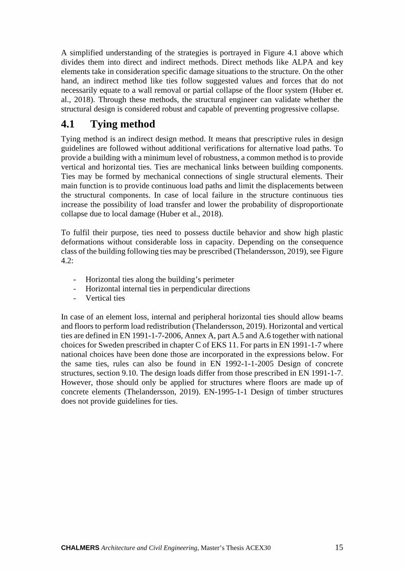
4.1 Tying method Tying method is an indirect design method. It means that prescriptive rules in design guidelines are followed without additional verifications for alternative load paths. To provide a building with a minimum level of robustness, a common method is to provide vertical and horizontal ties. Ties are mechanical links between building components. Ties may be formed by mechanical connections of single structural elements. Their main function is to provide continuous load paths and limit the displacements between the structural components. In case of local failure in the structure continuous ties increase the possibility of load transfer and lower the probability of disproportionate collapse due to local damage (Huber et al., 2018). To fulfil their purpose, ties need to possess ductile behavior and show high plastic deformations without considerable loss in capacity. Depending on the consequence class of the building following ties may be prescribed (Thelandersson, 2019), see Figure 4.2:
- Horizontal ties along the building’s perimeter - Horizontal internal ties in perpendicular directions - Vertical ties
In case of an element loss, internal and peripheral horizontal ties should allow beams and floors to perform load redistribution (Thelandersson, 2019). Horizontal and vertical ties are defined in EN 1991-1-7-2006, Annex A, part A.5 and A.6 together with national choices for Sweden prescribed in chapter C of EKS 11. For parts in EN 1991-1-7 where national choices have been done those are incorporated in the expressions below. For the same ties, rules can also be found in EN 1992-1-1-2005 Design of concrete structures, section 9.10. The design loads differ from those prescribed in EN 1991-1-7. However, those should only be applied for structures where floors are made up of concrete elements (Thelandersson, 2019). EN-1995-1-1 Design of timber structures does not provide guidelines for ties.

CHALMERS, Architecture and Civil Engineering, Master’s Thesis ACEX30 16
Figure 4.2 Horizontal and vertical ties in a framed structure.
The prescriptive rules for horizontal ties are defined in EN 1991-1-7, Annex A, part A.5. Different rules are prescribed for framed structures and load-bearing wall structures. The rules given in EN 1991-1-7, Annex A, part A.5.2 for load-bearing wall structure are not recommended to be used in Sweden. Additionally, the horizontal ties for framed and load-bearing wall structures should be designed according to the expressions prescribed in 17§ of EKS11 as described below (Thelandersson, 2019).
4.1.1 Peripheral ties Continuous ties shall be arranged around the perimeter of the building on each floor within a zone of 1.2 m along the floor edge. It is important that the ties are continuous even around the corner of the floor. The design tensile load !> in the ties should be determined as follows (Thelandersson, 2019):
!> ? 0.3 ∙ D-* E 8� ∙ 4*F ∙ 2� ∙ � (4.1)
Where:
-*= Characteristic permanent load on the floor GHIJ�K
4*= Characteristic variable load on the floor GHIJ�K
8�= Load combination factor for quasi-permanent variable load [-] 2�= Span perpendicular to the peripheral tie [m] �= The distance between two columns in longitudinal direction [m] Figure 4.3 shows an example of a framed structure with load bearing columns, beams, and slabs. In case where the vertical elements are made up of load bearing walls the distance L can be set to at least 3,6m or the entire length of the wall element (Boverket, 2019a). The characteristic variable load 4* depends on the type of building as defined in part C of EKS 11, see Figure 11.1 in Appendix B. The load combination factor for

CHALMERS Architecture and Civil Engineering, Master’s Thesis ACEX30 17
quasi-permanent variable load 8� for buildings depends on the type of space as defined in part B of EKS11, see Figure 11.2 in Appendix B.
Figure 4.3 Illustration of horizontal, peripheral, and internal ties.
4.1.2 Internal ties Continuous internal ties shall be arranged in two perpendicular directions, at each floor level of the building. The internal ties must be properly anchored in the peripheral ties or alternatively to vertical load bearing elements, i.e., columns or walls that form support for the floors. The ties must also be continuous over internal supports. Forces that must be absorbed by the internal ties must therefore be able to be transferred to walls or columns in the facade. If the internal ties can be equally spread over the floor area as for the transverse ties in Figure 4.3 the design tensile load should be determined according to equation (4.2). If it is not possible to evenly spread the ties across the floor area as for the longitudinal internal tie in Figure 4.3 the design tensile force should be determined according to equation (4.3) (Thelandersson, 2019):
4L ? 0.6 ∙ D-* E 8� ∙ 4*F ∙ 2� no greater than 80 G*N��K (4.2)
!L ? 0.6 ∙ D-* E 8� ∙ 4*F ∙ 2� ∙ � not greater than 600 [kN] (4.3)
Where: 2�= Average distance between 2� and 2� [m]
4.1.3 Vertical ties
Vertical ties are provided for two purposes, provide resistance to vertical elements against horizontal loads and the other to allow floors to be suspended from the storey above and thus limit the damage of collapse of a floor in case of accidental loss of a load bearing column or wall below. Therefore, each column and wall should be tied continuously from the foundations to the roof level.

CHALMERS, Architecture and Civil Engineering, Master’s Thesis ACEX30 18
The vertical ties should be capable of carrying a tensile force equal to the design force of permanent and variable load, from any floor, per meter of wall. The ties in the walls should also be evenly distributed. In other words, the capacity is determined so that the ties are capable of carrying the load acting on the floor above the removed wall or column (Boverket, 2019a). The capacity of the vertical ties in the longitudinal outer column line according to Figure 4.3 can be calculated as (Thelandersson, 2019):
!�O ? D-* E 8� ∙ 4*F ∙ 0.5 ∙ 2� ∙ � (4.4)
The vertical ties in the longitudinal inner column line according to Figure 4.3 can be calculated as:
!�Q ? D-* E 8� ∙ 4*F ∙ 2� ∙ � (4.5)
Vertical and horizontal ties are more common in steel and concrete structures where procedures such as grouting, or welding can be performed to provide continuity in connections. Diaphragms for timber structures such as walls and floor systems depend on steel connectors to benefit from load transfer mechanisms (Bita, 2019) and (Schneider, 2018). Therefore, robustness for timber elements is encouraged to implement the notional removal method.
4.2 Notional removal method The notional removal method also known as the alternate load path analysis (ALPA), is employed to analyse the behavior of a building in the notional removal of an element. A removed column or wall is applied when considering the building as a framed or load bearing wall structure, respectively (Huber et al, 2018). The main concept is to predict the consequences of the hypothetical situation. While the tying method provides reinforcement when subjected to specific loads, the notional removal method presents a more accurate approach when subjected to unidentified accidental actions. When referring to load-bearing wall construction, ALPA is considered the best approach as the structure can benefit from deep beam behavior of the walls, which is a major contributor to robustness in wall removal scenarios (Department of Defence, 2009).
4.2.1 Procedure The ALPA must be performed by removing one section of a wall at a time following design guidelines in (DoD, 2016, EN 1991-1-7, and Huber et al, 2018). There are three removal scenarios to consider when designing for robustness:
1. Removal of a nominal section of an interior wall 2. Removal of a nominal section of an exterior wall 3. Removal of a nominal section of an exterior corner wall
The first scenario presents the opportunity to floor systems to trigger catenary action as seen in Figure 4.4. Moment and rotational capacity are distributed through two wall-to-floor connections, thus transferring less tensile stress to the floor diaphragms. In the case on the exterior wall, catenary action is replaced by hanging action, further explained in section 4.3. While the contribution is diminished, the wall panels can act as a deep beam spanning over the removed wall area. These mechanisms work together

CHALMERS Architecture and Civil Engineering, Master’s Thesis ACEX30 19
to provide alternate load paths to supporting members of the structure. Following the removal of an element, possible collapse resistance mechanisms must be identified and their respective loads acting on the structures according to load factors and load combinations in Eurocode 1.
4.3 Collapse resistance mechanisms in load-bearing wall construction
4.3.1 Catenary action
Catenary action in load bearing wall structures is carried out by the slabs. In the scenario of a wall removal, disproportionate collapse can be prevented by vertical loads transferred to adjacent supports. With no bearing element below, the statically indeterminate structure must be designed to achieve the load redistribution through the horizontal elements as shown in the figure below.
Figure 4.4 Catenary action, with tensile force T, gravity load G and effects on the
remaining structure as dotted arrows, extracted from Huber et. al. (2018).
Catenary action occurs when the floor system is laterally restrained. Large deformations are a result of vertical loads from the walls above transforming into tensile forces. Ductility to withstand these deformations, which would otherwise induce failure in brittle materials like timber, are supplied by the connections (Moroder, 2016). As mentioned in section 2.1, a connection with adequate ductility and rotational capacity develops an elastic-plastic behavior. It is important to address the possibility of catenary action developing in timber structures has scarce literature where it has been researched. This collapse prevention mechanism is most common in structures where continuity of the horizontal elements can be guaranteed. In precast concrete structures, while robustness can be achieved solely with vertical and horizontal ties, the reinforcement grouted in the connection supplies the load transfer capability. Similar behavior can be seen with welding in steel structures. For timber structures, however, the situation is different that depends also on the type of construction desired (Moroder, 2016)

CHALMERS, Architecture and Civil Engineering, Master’s Thesis ACEX30 20
Figure 4.5 Novel steel-tube tension rod connection in platform-type construction.
Previous studies delve into different connections capable of having plastic behavior and providing load transfer mechanisms. Experimental research carried out by Mpidi Bita (2019) and Tannert (2018) show potential benefits of using novel steel tubes together with tension rods; see figure above. High tensile capacity and sufficient ductility to trigger catenary action are the highlights of such connection applied in platform-type constructions. A timber-concrete hybrid structure presents a challenge if any other type of construction is implemented. A balloon frame structure where load bearing walls are continuous cannot benefit from these transfer mechanisms. Thus, other alternatives must be developed to mimic similar tensile and rotational capacities.
4.3.2 Hanging action In the case an exterior supporting element is removed, instead of catenary action, the slab element will develop hanging action. The weight of the wall above causes displacement of the slab, and displacement causes rotation of the slab. The result is called hogging and sagging in the internal and external floor-to-wall connections, respectively, see Figure 4.6 below.
Figure 4.6 Hogging (left) and sagging (right) of the connection due to slab
rotation.
Pisarek (2015) developed an analytical model to study the internal force distribution in a steel beam-to-column connection when subjected to hogging and sagging. The hypothetical case was considered for a column removal scenario (Pisarek, 2015). Results showed that stresses due to bending could be translated into tensile and

CHALMERS Architecture and Civil Engineering, Master’s Thesis ACEX30 21
compression zones. The case study considered a bolted end plate connection and a composite slab on top, see Figure 4.7.
Figure 4.7 Distribution of internal forces due to hogging.
According to the connection’s composition, hogging of the slab will cause compressive stresses at the bottom and tensile stresses at the top. Such forces were transmitted through four components:
- A distributed tensile load across the height of the concrete slab (ft,c) - A tensile force in the reinforcement steel (Ft,s) - Top bolt subjected to a tensile force (Ft,b,2) - Bottom bolt subjected to a compressive force (Fc,a)
Similar models are recommended when designing the connection. Components and stresses will differ according to the type of connection, cross-section of the horizontal and vertical elements, and connectors involved. Once the model of distribution of internal forces is performed, these are to be compared with technical specifications of manufacturers’ products that can withstand these stresses in order to prevent progressive collapse.
4.3.3 Deep beam behavior Floor and wall diaphragms composed by multiple panels, as seen in Figure 4.8, subjected to a distributed load trigger a behavior similar to a simply supported beam. Given the dimensions of shear or load bearing walls, this is interpreted as deep beam behavior (Moroder, 2016). The analogy idealizes the geometry to determine the force distribution across the diaphragm.

CHALMERS, Architecture and Civil Engineering, Master’s Thesis ACEX30 22
Figure 4.8 Mechanism of floor and wall diaphragms: a) shear forces; b) bending
moment.
With the shear and bending moment exemplified, the load distribution to adjacent supporting elements is carried out by panel-to-panel connectors working in shear. In a study by Daniel Moroder (2016) regarding floor and wall diaphragms in multi-storey buildings, the finite element analysis performed confirms the deep beam behavior triggered in the diaphragm. Figure 4.9 illustrates the presence of both tension and compression zones. In a reinforced concrete beam, these stresses are absorbed by steel reinforcement in the bottom and top part of the cross-section. Precast wall diaphragms achieve this through bolted or screwed steel fasteners.
Figure 4.9 FE model of deep beam behavior in wall panel diaphragms.
Performance of a wall diaphragm is determined through Serviceability Limit State (SLS) analysis. Prevention of progressive collapse and robustness requirements allow for larger deformations due to accidental loads. Following capacity based design, these deformations must occur in the panel to panel connection. Figure 4.10 shows an idealized force distribution (a) where shear forces are distributed along the height of the wall and critical tensile and compressive stresses are more critical at the top and bottom of the cross section.

CHALMERS Architecture and Civil Engineering, Master’s Thesis ACEX30 23
Figure 4.10 Force distribution for diaphragm panel connections subjected to deep
beam behavior.
However, prefabricated wall panels are connected via a select number of steel fasteners with determined spacing along the height of the wall according to Eurocode 2 standards (CEN, 2006). Additionally, tensile and compressive stresses are present across the entire height of the wall, which means that the location of each connector will determine the magnitude of both shear and/or tensile and compressive stresses in each of them. Hence, a real force distribution (b) provides simplified but accurate information to verify ductile behavior of the connection to meet robustness requirements.
4.3.4 Membrane action In load bearing wall construction, the notional removal method presents the floor system as a contributor towards robustness and prevention of progressive collapse. With continuity provided through the panel-to-panel connections, the slabs behave as a membrane or shell with the ability to redistribute loads to adjacent supports (Huber et. al., 2018). In case of an inner column removed, see Figure 4.11, vertical loads are redistributed to the adjacent columns.
Figure 4.11 Membrane action in floor diaphragms.
Panel-to-panel connections are commonly perpendicular to the action load; thus, the stability depends on the shear capacity of the connectors. Fasteners in panel-to-panel connections have a ductile behavior when subjected to shear loads (MTC, 2019). Membrane action, catenary action, and deep beam behavior all play a role in the prevention of progressive collapse. The contribution of each will depend on the removal scenario described in section 4.2. For CLT floor systems, dowel-type fasteners such as screws and bolts are critical elements to provide ductility and the capacity for the

CHALMERS, Architecture and Civil Engineering, Master’s Thesis ACEX30 24
connectors to work in shear when the panels are subjected to tensile stresses (Schneider, Tanner, 2018).

CHALMERS Architecture and Civil Engineering, Master’s Thesis ACEX30 25
5 Environmental impact
5.1 Life cycle analysis Life cycle analysis (LCA) is a method for calculating the environmental impact during a product's entire life cycle. With an LCA it is possible to find out at what stage of a building's life cycle a certain environmental impact is greatest and at what stage the greatest environmental improvements can be done (Boverket, 2019a). Designing and building a house with a low environmental impact is an important part of contributing to a more sustainable society. The greatest opportunity for environmental improvements to be done by comparing different design alternatives and choice of materials is during the design phase while during construction the chances for environmental improvements are lower since the material and product choices are already done. The life cycle of a building is divided into following three main stages (Boverket, 2019a), see Figure 5.1:
- A- The construction stage - A1-A3 Product stage - A4-A5 Construction process stage
- B- the use stage - C- the end-of-life stage
The LCA stages are divided into sixteen information modules that describe the processes during the life cycle. The product stage (A1–3) includes all steps from extraction of raw materials to manufacturing of the construction products. The construction process stage (A4–5) includes transport and installation of the construction products to the site. The use stage (B1–7) includes use, maintenance, repairs and operation of the building. The end of life stage (C1–4 ) includes all processes from demolition to disposal of the building parts (Swedish Institute for Standards, 2013).
Figure 5.1 Life-cycle stages and modules for LCA assessment of buildings.
In an LCA, the environmental impact is described by seven environmental impact categories or so-called environmental indicators. An LCA may be based on one or more of those categories presented next (Boverket, 2019d):
- Global warming potential (GWP) - Acidification for soil and water potential (AP) - Eutrophication potential (EP)
CHALMERS, Architecture and Civil Engineering, Master’s Thesis ACEX30 26
- Depletion of abiotic resources potential – non fossil resources (ADPe) - Depletion of abiotic resources potential – fossil resources (ADPf) - Ozone depletion potential (ODP) - Photochemical ozone creation potential (POCP)
Climate impact is nowadays considered as one of the biggest environmental threats. It is therefore common to limit the LCA for buildings to the GWP indicator. A calculation of this kind is also called a climate footprint (Boverket, 2019b). The GWP indicator has the unit kg CO2-equivalents and represents the total emission from all greenhouse gases (GHG). The main three GHG are: carbon dioxide (CO2), methane (CH4), and nitrous oxide (N2O). Different GHG have different effects on the Earth's warming. To be comparable, the emissions from all GHG except CO2 are multiplied by a GWP factor. By this factor, the GHG are converted into CO2-equivalents. For example, the GWP factor for CH4 is 25 and for N2O, 298. One kilogram of CH4 emissions equals to 25 kg of CO2-equivalents (Naturvårdsverket, 2021).
5.2 Environmental product declarations The environmental impact of a construction product during its lifetime is described by an environmental product declaration (EPD), carried out by the manufacturers. It is a standardized tool to communicate the environmental performance of a product. The information in an EPD is based on the life cycle analysis of the product itself and the result can be used when performing a LCA for an entire building. (Boverket, 2019c). Prior to the LCA of a product there are several rules that must be followed. The rules are called product specific rules (PCR) and consider what information to include, what data to use and what environmental indicators to report, etc. EPDs for different products and from different manufacturers can be compared but they must be based on the same PCR. There are three different levels of environmental declarations for products, type I, type II and type III declarations. The most comprehensive declaration is the type III environmental declaration which results in an EPD. A type III declaration is third party reviewed and based on PCR and LCA (Del Borghi, 2013).

CHALMERS Architecture and Civil Engineering, Master’s Thesis ACEX30 27
6 Design The case study used for this thesis is a residential complex composed of four structures. The project is named Rådjuret located in Malmö. The structure is a precast concrete load-bearing wall construction with simply supported slabs. The slabs span in one direction with continuous walls, also known as a balloon-framed structure.
Figure 6.1 3D view of the case study structure.
The consequence class of this complex is determined according to Table A.1 in EN-1991-1-7 and a categorization figure by Consolis Stränbetong, see Appendix A. First, three characteristics were identified that influence the consequence class:
1. Determine building type 2. Determine number of stories 3. Determine the floor area
The building type is a multi-familiar residential complex. Seeing in Figure 6.1 that all buildings have different number of stories, the tallest structure (9 stories) will govern the design. With these characteristics and a floor area of 3094 m2, the consequence class is set as “2b” according to EN 1991-1-7 or “CC2b” according to Strängbetong’s categorization. For building in consequence class 2b, horizontal and vertical ties should be applied in all supporting walls and columns. As an alternative, the notional removal method can be applied (CEN, 2006). As mentioned in section 4.2, the notional removal method is the recommended method for load-bearing wall construction if tying cannot be achieved. The original design achieved robustness demands through the tying method. Wall-to-wall connections are carried out through grouted vertical ties. Floor-to-wall connections are carried out through grouted horizontal ties.

CHALMERS, Architecture and Civil Engineering, Master’s Thesis ACEX30 28
6.1 Design strategy The pursuit of dismountable connections offers the opportunity to identify possible alternatives that avoid the use of grouting or welding. The building configuration presents no interior load-bearing walls. Slabs span in one direction and stability against horizontal forces is treated with precast concrete shear walls. This limits the possibility of having catenary action as a collapse resistance mechanism. To achieve robustness, it was determined that a concrete-timber hybrid structure required a combination of two different methods, the tying, and the notional removal method. By replacing precast hollow-core slabs with CLT floors, the floor-to-wall interaction changes. However, the wall-to-wall interaction remains unchanged as they are still composed of precast concrete. This analysis led to having two different combinations of materials, and the possibility of transforming a 3D interaction into two-dimensional cases, see Figure 6.2 below.
Figure 6.2 Concrete-to-concrete interaction (left) and concrete-to-timber
interaction (right).
6.1.1 Wall-to-wall interaction With a balloon framed structure, the load-bearing walls must benefit from continuity, irrespective of the floor-to-wall connection. A frontal view of the structure can be interpreted as a precast structure, not a hybrid structure. Eurocode 2 recommends the tying method for precast concrete structures. In this case, the vertical wall-to-wall connections are to be made with vertical ties. Exclusive from an alternate load path analysis, vertical ties are part of the provision of robustness according to EN 1991-1-7. However, wall-to-wall connections also play a role in the notional removal method. Considering a scenario where a lower wall is removed, the wall connections will help the structure to trigger deep beam behavior as described in section 4.3.3.
6.1.2 Floor-to-wall interaction With no inner walls, the possible collapse resistance mechanisms in the floor-to-wall connection are hanging action and membrane action. These mechanisms are exclusive to the notional removal method. Commonly, hollow-core slabs are connected to the lower supports via concrete or steel corbels. In a wall removal scenario, this

CHALMERS Architecture and Civil Engineering, Master’s Thesis ACEX30 29
configuration would cause the slab to collapse. To trigger hanging and membrane action, the floor system must be attached to the supports above the removed wall (DoD, 2016). Membrane action should trigger if the panel-to-panel connections have sufficient capacity when subjected to shear stresses. In the case of precast structures, the in-plane stresses in the hollow-core slabs are transmitted by the horizontal ties grouted in the floor-to-wall connections. As deformations are greater at the edges, the ductility of the steel reinforcement contributes to the deformation capacity of the floor system. In literature, timber floor systems are considered brittle, especially when subjected to in-plane stresses perpendicular to the grain. With cross-lamination in CLT floors, its strength is much higher. However, common CLT panel-to-panel connections, see Appendix D are not designed for high deformations as expected in wall removal scenarios. As deformations increase closer to the connection, a connector with higher ductility between panels is recommended to trigger membrane action.
6.1.3 Wall removal scenarios As described in Section 4.2.1 for an ALPA three wall removal scenarios needs to be considered. The case study building does not have any internal load bearing walls. Thus, in that case only two wall removal scenarios needs be considered: removal of a corner wall and a façade wall. The worst case scenarios appears when the longest wall elements for the both cases are removed. Figure 6.3 shows an overview of the four blocks of the case study building.
Figure 6.3 South-east view of four blocks of the building
The location of the longest corner wall element, scenario 1, is identified at the south-east corner of the eastern block of the building. The length of the removed wall is 7.0 m with a height of 2.9 m. Figure 6.4 shows a plan view of the four building blocks with the location of the removed corner wall highlighted with green colour.

CHALMERS, Architecture and Civil Engineering, Master’s Thesis ACEX30 30
Figure 6.4 Scenario 1: Identification of removed corner wall, eastern block
For scenario 2, the location of the longest removed façade wall element is identified to be in the north block of the building. The length of the removed wall is 7.5 m with the same height as for the corner wall 2.9 m. Figure 6.5 shows a plan view with the identified location of the removed façade wall element highlighted with green colour.
Figure 6.5 Scenario 2: Identification of removed façade wall in northern block

CHALMERS Architecture and Civil Engineering, Master’s Thesis ACEX30 31
6.2 Wall-to-wall connections Assembly and disassembly of the connection is available through the use of PEIKKO group certified SUMO wall shoes. The connection consists of wall shoes cast into precast concrete walls at the lower end and anchor bolts at the upper end. The assembly on site is performed by adjusting the plate into the correct position and fastening the connection with nuts and washers (PEIKKO, 2014), see Figure 6.6.
Figure 6.6 SUMO wall shoe and anchor bolt wall connection.
The anchor bolts are casted in the production stage. Grouting the wall shoe after assembly is optional for aesthetics purposes. The main structural behavior is carried out by the anchor bolts which activate when the walls are subjected to tensile forces. Additionally, the connection serves also to prevent horizontal displacement of the elements. Such a connection is considered a dry connection because it requires no grouting or welding, see Figure 6.7.
Figure 6.7 Wall shoe mechanical connector.
The tensile stresses expected on these connections can be determined through equations (4.4) and (4.5) of the tying method. The tensile stresses are transferred by vertical continuity reinforcement lapped together with both the wall shoe and the anchor bolt. This system benefits from the standardized manufacturing to meet the strength required. In-situ casting and welding have a higher risk of having deficiencies due to human error. On the other hand, consistent quality can be guaranteed for this type of connection.

CHALMERS, Architecture and Civil Engineering, Master’s Thesis ACEX30 32
Values obtained from EN-1991-1-7 and Swedish design codes EKS 11 were compared with the different design strengths provided by the manufacturer in Table 6.1 below. Table 6.1 Design resistance values of SUMO wall shoes for concrete grade
C25/30
Wall shoe Anchor bolt Washer �� [kN]
SUMO 16H HPM 16 AL 16 62
SUMO 20H HPM 20 AL 20 96
SUMO 24H HPM 24 AL 24 139
SUMO 30H HPM 30 AL 30 220
SUMO 39H HPM 39 AL 39 383
SUMO 30P PPM 30 AL 30 299
SUMO 36P PPM 36 AL 36 436
SUMO 39P PPM 39 AL 39 521
SUMO 45P PPM 45 AL 45 697
SUMO 52P PPM 52 AL 52 938
According to guidelines in the United Facilities Criteria (DoD, 2016) and Australian Wood Solutions (Hewson, 2016), the tensile force, see Figure 6.8, due to gravity loads are redistributed through the vertical ties to connections above the removed element.
Figure 6.8 Transmission of the tensile forces across the anchor bolts.
In case of a wall removal scenario, this distribution causes the floor-to-wall connections of story’s above to replicate the same behavior seen in Figure 6.9. Each subsequent floor will be subjected to the same deformations, each capable of triggering similar collapse resistance mechanisms (Huber, 2019). As a result, the design for the loads and stresses in the connection amount to the gravity load of the slab itself and only the wall above.

CHALMERS Architecture and Civil Engineering, Master’s Thesis ACEX30 33
Figure 6.9 Load redistribution through vertical ties into floors above.
Source: Wood Solutions: Robustness in structures
6.2.1 Connection design The design loads for the wall-to-wall connections were calculated for the original design and the proposed solution based on two wall removal scenarios. One scenario is when a corner wall of the building was notionally removed, and second when a façade wall was notionally removed. For both cases, the design loads were calculated for the whole element length and per meter of the wall element. The results were compared with the capacity of the wall shoes to determine the type and amount of wall shoes needed according to Figure 6.5. The calculations were done according to Section 4.1.3 and equation 4.4 and are presented in Appendix E. The case study building is a residential building. The characteristic permanent load -* acting on the floors were determined from the self weight of the hollow-core and CLT elements according to Table 12.3 in Appendix B and Table 12.3 in Appendix C. The characteristic variable load 4* acting on floors in buildings depend on type of space and floor. The value for Category A, floors in rooms and spaces in residential buildings according to Figure 11.1 in Appendix B were used. The load combination factor 8� for quasi permanent variable load for rooms and spaces in residential buildings (Category A) according to Figure 11.2 in Appendix B were used. For both scenarios, the distance between the vertical ties or the span 2� according to Figure 4.3 were same. The distance � were set to the elements length and are different for the two scenarios. The data used for the calculations are summarized in Table 6.2. Table 6.2 Input values for design loads of wall-to-wall connections
Design alternative/Scenario -* VkNm� Y 4* VkN
m� Y 8� 2�[m] �[m]

CHALMERS, Architecture and Civil Engineering, Master’s Thesis ACEX30 34
Hollow-core slabs 3.37 2.0 0.3 10.7
Scenario 1- removal of a corner wall 7.0
Scenario 2- removal of a façade wall 7.5
CLT slabs 1.06 2.0 0.3 10.7
Scenario 1- removal of a corner wall 7.0
Scenario 2- removal of a façade wall 7.5
The results from the calculations show higher design loads for the original design with hollow-core floor elements for both scenarios, see Table 6.2. The results are expected since the only difference between the two design alternatives is the self-weight of the structural elements. By exchanging hollow-core with CLT floor panels the design tensile load is reduced by approximately 60%. For both alternatives, the removal of the façade wall, scenario 2, shows higher design loads for both design alternatives due to longer wall elements. The design load per meter of wall is same for both design alternatives and scenarios due to the same span of floor elements. For the original design, three wall shoes SUMO 16H are required to absorb the design tensile load in both scenarios, see Table 6.1. For the proposed solution two wall shoes of the same capacity are needed which is almost the double of the capacity required. Less amount of wall shoes for the proposed solution can speed up the production of wall elements in factory and reduce the assembly time required on site. Table 6.3 Design loads for wall-to-wall connections for hollow-core and CLT
slabs
Design alternative/Scenario !�O[kN ] !�O� VkN
Z Y Wall shoes
SUMO 16H[3]
Hollow-core slabs
Scenario 1- removal of a corner wall 149.16 21.28 3
Scenario 2- removal of a façade wall 160.22 21.28 3
CLT slabs
Scenario 1- removal of a corner wall 62.28 8.88 2
Scenario 2- removal of a façade wall 66.90 8.88 2
6.3 Floor-to-wall connections Similar to wall connections, grouting and welding are to be avoided in the connections. Should an element be damaged, a dismountable connection allows the construction team to replace the element without compromising other structural elements of the building. Considerations studied in Capacity Based Design provide an advantage in the cost-benefit analysis. The cost of a connection’s components is lower than the cost of replacing an entire element. Self-tapping screws (STS) and lag screws are the common connectors in timber structures. Loads perpendicular the grain of the CLT floors subject the connectors to withdrawal forces. These connectors have a limited withdrawal capacity. For higher loads in case of accidental actions, the withdrawal capacity was not considered the correct approach.

CHALMERS Architecture and Civil Engineering, Master’s Thesis ACEX30 35
Figure 6.10 Withdrawal behavior of lag screws from CLT face lamination.
Solid timber and CLT both have the same weakness when subjected to axial loads in directions as seen in Figure 6.10 above. Cross-lamination provides little to no contribution (EWPAA, 2018). Additionally, multiple insertions and extractions of the connectors have the risk of reducing the withdrawal capacity. A better connection design that does not subject the CLT floor to these types of stresses is recommended.
6.3.1 Alternative 1 The first alternative connection design consists of an upper angle bracket attaching the CLT slab to the wall above. The steel-to-concrete connection has standard connectors with screws subjected to shear. To avoid risk of withdrawal in the CLT connection, bearing plates were implemented in the lower part of the slab as seen in Figure 6.11 below.

CHALMERS, Architecture and Civil Engineering, Master’s Thesis ACEX30 36
Figure 6.11 Alternative 1 conceptual design.
The bearing plate, manufactured by Simpson Strong-Tie, prevents the risk of failure due to withdrawal or pull-through of the anchor bolts. Instead, the load is distributed over the width of the bearing plate. The result is a conversion from an axial load to a compressive stress applied on the CLT floor. Failure due to compression perpendicular to the grain has a ductile behavior in cross-laminated timber.

CHALMERS Architecture and Civil Engineering, Master’s Thesis ACEX30 37
Figure 6.12 Internal load distribution due to sagging in alternative 1.
According to the notional removal method, the floor and wall were subjected to sagging as the lower support was removed. With the alternative 1 design configuration, the stress distribution in Figure 6.12 Figure 6.13 were replicated according to internal force distribution in section 4.3.2. The distribution consists of pull-through of the anchor bolts (1) due to floor loads q, a distributed compressive stress due to bending of the angle bracket applied in the cross section of the precast concrete wall, shear stress in the steel-to-concrete connection interface (3) due to vertical loads G in the wall above, and a distributed compressive force (4) perpendicular to the grain as a reaction to the sagging of the timber element.
Figure 6.13 Internal load distribution due to hogging in alternative 1

CHALMERS, Architecture and Civil Engineering, Master’s Thesis ACEX30 38
The hogging effect of the adjacent supports have a different effect. Since the loads applied after the wall removal cause a closing of the angle bracket in the connection above the removed wall, the angle bracket in the adjacent supports was subjected to opening. The pushdown force causes a rotation of the CLT element, and as a result, the elements cause a compressive force into the face of the concrete wall. The horizontal load applied was countered with an equal reaction from the concrete element. The compressive strength of the concrete absorbed a portion of the pushdown force, thus reducing the load applied on the angle bracket.
Figure 6.14 Hanging action of alternative 1; hogging (left) and sagging (right).
The main connector of the CLT slab to the concrete wall is the angle bracket. The interface between the concrete and timber elements has no attachment. Due to this configuration, hanging action developed in both ends of the elements provided different types of stresses on each material. The rotation of the CLT slab due to hogging in Figure 6.14 above caused a pullout force in the steel-to-concrete connectors. The rotation revolved around the neutral axis of the connection, which is at the steel-timber interface. Consequently, the rotation caused a compressive force applied by the CLT slab pushing into the wall. The floor-to-wall connection above the removed element is subjected to sagging. The rotational stiffness of the angle bracket and hogging of the CLT slab are expected to provide enough deformation capacity to trigger a load redistribution through the floor element. The downward force caused by the wall transformed the stress of the anchor bolts into a tensile stress applied in the cross-section of the slab.

CHALMERS Architecture and Civil Engineering, Master’s Thesis ACEX30 39
Figure 6.15 Alternative 1 floor-to-wall and wall-to-wall connection.
6.3.2 Alternative 2
The second alternative implements similar concepts than the first design with additional support for vertical loads which also contribute against possible collapse. Simply supported slabs rely in the floor loads to be supported by corbel and angle brackets and transmitted to the wall. Another option was to have the floor rest directly on the wall. It is much more reliable having a concrete wall acting in compression rather than relying on the withdrawal capacity and shear strength of the connectors.

CHALMERS, Architecture and Civil Engineering, Master’s Thesis ACEX30 40
Figure 6.16 Alternative 2 conceptual design.
Figure 6.16 shows the CLT element resting on the wall below during normal conditions. Outside of the effects on accidental actions, the bolted connections are not expected to have any mechanisms triggered except for horizontal loads included in the standard structural design of the building. Vertical loads are transferred directly from wall to wall. The contribution of the designed connection starts when a wall is removed in the ALPA. The sagging effect in the connection above the removed wall was expected to have the same behavior and internal load distribution as Figure 6.12. However, main difference and potential for higher contribution lies in the hogging effect in Figure 6.16. A study was performed by Huber (2019) regarding FE models of alternative load paths in CLT buildings with angle bracket connections in platform-type construction. Simulations showed that the clamp or sandwich effect between both walls and the CLT slab was a major contributor towards the rotational stiffness when subjected to cantilever action. (Huber, 2019). Considering that the slab was a bearing element, the friction resultant of the vertical loads increased the rotational stiffness of the overall connection. The vertical loads on the CLT floor due to wall removal would cause an uplifting force applied on the wall above. The reaction forces, see Figure 6.17, to counter these effects have three contributors:
1. The rotational stiffness of the angle bracket against hogging 2. The self-weight of the wall above 3. The vertical ties existing in the wall-to-wall connections

CHALMERS Architecture and Civil Engineering, Master’s Thesis ACEX30 41
Figure 6.17 Reaction forces against uplifting force applied by the slab
The vertical ties designed in section 6.2.1 have the tensile capacity equal to the loads applied on the flooring system. These three contributors will increase the overall stiffness of the connection and preventing higher deformations of the connection. The effects predicted with this configuration correlate the purpose of providing sufficient ductility to the connection. It must be considered that the higher the stiffness, large deformations are limited, which reduces the capability of load redistribution through alternative load paths. Not allowing the element to rotate to a certain degree, will cause higher stresses in the element rather than in the connection. The type of failure expected due to high stiffness is brittle failure of the timber elements.
6.3.3 Alternative 3 Alternative 3, see Figure 6.18, expands on the feasibility of the first alternative. It considers the installation procedure of slab elements in balloon-framed construction. The placement of slabs before their fastening to the slabs would require a provisional support for the slabs to rest in. This was achieved with steel corbels attached to the wall below. The connection between the corbel and the CLT element would be considered a simply supported slab with only the friction between the two materials as a brace. In the alternate load path analysis, the wall removal would also eliminate the steel corbel from acting as a support. Under normal conditions, similar behavior as alternative 2 is expected. Gravity loads would be transferred through the steel corbel below, leaving the designed floor-to-wall connection not being induced to any loads.

CHALMERS, Architecture and Civil Engineering, Master’s Thesis ACEX30 42
Figure 6.18 Conceptual design of alternative 3
During the procedure of the notional removal method, the hogging effect, see Figure 6.19, replicates similar effects from both alternative 1 and alternative 2. The rotation of the slab would induce compressive stresses to the concrete wall, thus increasing the overall stiffness of the connection. Rotation of the slab together with the floor loads acted upon the lower steel corbel. With similar rotational stiffness than the upper brackets, the bending of the connector replicated the sagging effect of the connection above the removed wall.
Figure 6.19 Internal stress distribution due to hogging, alternative 3

CHALMERS Architecture and Civil Engineering, Master’s Thesis ACEX30 43
6.4 Results Each of the alternatives presented consists of different components that contribute towards robustness. The results of the analysed the potential contributors are listed in Table 6.4. The relevance of each contributor depended on the criteria to reach the goals of preventing progressive collapse. Table 6.4 Existing contributing components against progressive collpase
Contributor Alternative 1 Alternative 2 Alternative 3
Sagging of angle bracket Yes Yes Yes
Hogging of angle bracket Yes Yes Yes
Compression strength of wall Yes Yes Yes
Uplift of wall due to hogging No Yes No
Vertical ties No Yes No
Clamping No Yes Yes
Deep beam behavior Yes Yes Yes
Although the contributing components in the table above seem a benefit overall, each alternative must consider the concepts to reach ductile failure. As mentioned in Chapter 2 of this study, the connections are a key component to redistribute loads to adjacent supports in case of failure or accidental loads. However, the redistribution can only be achieved through a connection with sufficient ductility. The higher stiffness in the connection, considered initially a benefit, prevents load redistribution by restricting large deformation in the connections. A connection with to high stiffness could cause a brittle failure in the connection and the elements. With this concept mind, a retroactive analysis of the alternatives is recommended.
6.4.1 Alternative 1 Out of the six possible components to contribute against progressive collapse, a connection with only upper angle brackets only depends on the rotational stiffness of the angle bracket. Under normal conditions where no wall is removed or accidental loads applied, floor loads must also be transferred through the bolts in the steel-to-concrete connection. The connection will constantly work in shear. In terms of installation procedures, no provisional supports are supplied, thus increasing the complexity of attaching the CLT elements to the concrete walls. As a result, human error might come into place where the connections are not aligned horizontally nor vertically.
6.4.2 Alternative 2 The second alternative where the slabs are slotted in between the walls approximate a platform-type structure. In the connection where the wall has been removed, neither of the alternatives are affected by this configuration. Only the hogging effect in the adjacent supports benefitted from the clamping mechanism. According to calculations in Appendix G, the opening or closing of the angle bracket was analysed through an equilibrium to determine the bending moment applied on the horizontal flange of the

CHALMERS, Architecture and Civil Engineering, Master’s Thesis ACEX30 44
steel connector. The hogging of the angle bracket and rotation of the CLT element were predicted to cause an uplifting force that would be countered by the vertical loads originating from the upper wall. The resultant force caused a negative bending moment to counter the bending moment from the pushdown force of the slab, see Figure 16.1. The final bending moment on the angle bracket would be reduced, thus resulting in a lower rotation of the flange. The rotation capacity of the flange together with the clamping effect increase the stiffness of the connection, reducing the possibility of large deformation to achieve load redistribution.
Figure 6.20 Tensile load on CLT slab due to sagging of angle bracket
The rotational stiffness of the angle bracket is relevant to the magnitude of loads transferred through stresses parallel to the span of the CLT element. The vertical loads Gv as a result of the wall removal need to be transferred through the slab to the adjacent load-bearing walls. The decomposition of forces in Figure 6.20 show that as the angle of rotation increases, the loads applied on the slab are reduced.
Figure 6.21 Angle bracket rotation vs CLT tensile load curve
As seen in Figure 6.21, the rotation of the angle bracket is inversely proportional to the tensile load the CLT slab would need to sustain. A higher stiffness of the connection results in a lower rotation angle of the flange. In other words, the angle bracket needs

CHALMERS Architecture and Civil Engineering, Master’s Thesis ACEX30 45
to bend in a range where the tensile loads do not exceed the design tensile strength of the CLT element. The geometry required for the concrete walls and CLT elements could limit the adaptability of the floor-to-wall connection to other types of construction. Installation of this type of connection includes having the slabs rest of the wall. A step towards ease of disassembly involves not disturbing other structural elements. The “slotted” insertion of the slab complicates the installation procedure of the slabs if upper walls have already been installed. Balloon-framed buildings benefit from load-bearing walls unaltered by other elements, like slabs. Also, the inclusion of vertical in between the cross-section of the wall could be limited by the insertions. Additionally, an unusual geometry of the elements counters the idea of promoting simplicity of installation procedures.
6.4.3 Alternative 3 Alternative 3 borrowed from the better features of the first two alternatives towards assuring a ductile failure. The clamping effect, though it increasing the load carrying capacity, does so in a manner the moves away from ductile failure. With an upper angle bracket, the rotational stiffness will depend mostly on the mechanical properties and strength of the connectors, not of other vertical elements. This approach allows for this configuration to adapt to the types of construction which will not require specific geometrical features of both vertical and horizontal elements. With lower and upper angle brackets, normal and accidental loads, respectively, will be exclusive to each connector. Assembly and disassembly of the connection is expected to be simplified with no disturbances to other structural elements. Finally, the conservative approach would be to determine if the angle brackets and bolts could themselves sustain the loads in the alternate load path analysis. In conclusion, the most efficient approach to achieve a ductile behavior with load carrying capacity according to the ALPA is the third alternative, with upper angle brackets for the accidental design loads and lower angle brackets to sustain gravity loads under normal conditions
6.4.4 Design validations The angle bracket was designed to sustain quasi-permanent loads from both the floor loads and the vertical wall above the connection. Each CLT element was required to be installed individually, therefore the design was performed for one element of 1.20m, resulting in a design as:
�� ? 32.18 0� The sagging effect caused a bending of the upper angle bracket above the removed wall. The material and geometrical properties of the angle bracket in the design are detailed in Table 6.5. Table 6.5 Geometrical and material properties of angle bracket
Yield strength, fy 250 MPa
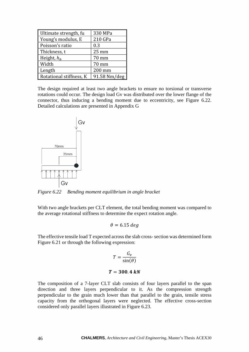
CHALMERS, Architecture and Civil Engineering, Master’s Thesis ACEX30 46
Ultimate strength, fu 330 MPa
Young’s modulus, E 210 GPa
Poisson’s ratio 0.3
Thickness, t 25 mm
Height, ℎ� 70 mm
Width 70 mm
Length 200 mm
Rotational stiffness, K 91.58 Nm/deg
The design required at least two angle brackets to ensure no torsional or transverse rotations could occur. The design load Gv was distributed over the lower flange of the connector, thus inducing a bending moment due to eccentricity, see Figure 6.22. Detailed calculations are presented in Appendix G
Figure 6.22 Bending moment equilibrium in angle bracket
With two angle brackets per CLT element, the total bending moment was compared to the average rotational stiffness to determine the expect rotation angle.
9 ? 6.15 %^- The effective tensile load T expected across the slab cross- section was determined form Figure 6.21 or through the following expression:
! ? ��sinD9F
b ? cdd. e fg
The composition of a 7-layer CLT slab consists of four layers parallel to the span direction and three layers perpendicular to it. As the compression strength perpendicular to the grain much lower than that parallel to the grain, tensile stress capacity from the orthogonal layers were neglected. The effective cross-section considered only parallel layers illustrated in Figure 6.23.

CHALMERS Architecture and Civil Engineering, Master’s Thesis ACEX30 47
Figure 6.23 Effective cross section of CLT slab parallel to the span direction
With the materials properties extracted from the manufacturer and corroborated with Swedish CLT Handbook (2019), the design tensile strength of the effective cross section was determined through the following expression:
&+,), ? 0�1 ∗ &+,),*:;
Where: &+,),* = characteristic tensile strength parallel to the grain, MPa &+,), = design tensile strength parallel to the grain, MPa 0�1 = modification factor for safety class and load duration :; = partial safety factor for CLT
ij,d,k ? lm. cm nop The design tensile load T was distributed across the effective cross-section and compared to the tensile strength of the element &+,), .
bk ? bqri
? l. cs nop
bk < ij,d,k
u6v2vwx6vy3 zx6vy ? 12%
With a design load that only reaches 12% of the overall capacity of the CLT element, brittle failure could be avoided as long as the shear capacity of the bolts would yield before it. Following recommendations and studies carried out by Mpidi Bita (2019) and corroborated with Eurocode 3 guidelines, bolts with 25mm diameter were selected. These were verified through design procedures expressed in EN 1993-1-8. With a resultant shear stress �� , the number of bolts required were determined as following.
�� ? 139 0�
! ? 300.4 0�
~� ? b��
? m. m → c ���j�
For the total design load T, three 25mm bolts were necessary. With two angle brackets per CLT element, a total number of four bolts were implemented. Thus, the total load carrying capacity of the bolted connection was 556 kN.

CHALMERS, Architecture and Civil Engineering, Master’s Thesis ACEX30 48
u6v2vwx6vy3 zx6vy ? 300.4 0�556 0� ? 54%
With a utilization ratio of 54% compared to 12% of the CLT tensile strength, the bolts would yield before reaching the design capacity of the CLT element. According to these results it was concluded that the criteria of Capacity Based Design was achieved. The CLT slab, as a result, possessed an overstrength factor of 4 compared to the bolts. Following recommendations from Mpidi Bita (2019), a minimum overstrength factor of 1.6 should be achieved to ensure the trigger of hanging action to prevent progressive collapse.

CHALMERS Architecture and Civil Engineering, Master’s Thesis ACEX30 49
7 Estimation of carbon footprint In the following section simplified calculations were done to estimate the CO2 emissions and thus the contribution to the climate footprint for the original design and the proposed solution. The original design consists of floors made up of hollow-core slabs vs the proposed design with floors made up of CLT panels. The results for the different designs were then compared to gain a better understanding of the potential change an alternative solution would produce. The necessary data used for the calculations and comparison are extracted from EPD’s for hollow-core and CLT elements provided by the manufacturers Strängbetong AB and Martinsons Trä, see Appendix C. The EPD for CLT provides only information for the product stage A1-A3. The EPD for hollow-core provides declared values even for the construction process stage A4-A5 and the end-of-life stage C1-C4. Based on the EPD for hollow-core one can conclude that the highest contribution to the GWP is from the product stage, see Table 12.1 in Appendix C. Since both CLT and hollow-core are prefabricated elements and thus have similar transport and installation procedures one can assume that CLT have similar GWP values as hollow-cores for the construction process stage A4-A5, use stage B1-B7 and the end-of-life stage C1-C4. For the purpose of this thesis the calculations and comparison will only include the data from the product stage A1-A3 due to the conclusion that the highest environmental improvements can be done in this stage. The floor in the case study is composed of two different hollow-core elements, HD/F-27 with a sectional height of 270 mm with a total element area of 11679 m2 and HD/F-40 with a sectional height of 400 mm and a total element area of 1120 m2 . Due to the different sectional height, hollow-core sections contain different amounts of concrete and reinforcement and thus have different declared GWP values. The declared GWP values for product stage A1-A3 for different hollow-core’s and per m2 of element are presented in Appendix C, Table 12.1. For CLT, the GWP values are declared per m3 of material and are presented in Appendix C, Table 12.3. To be able to compare the environmental impact of CLT and hollow-core elements the calculations and comparison are done per m2 of the element and the total element area. For the purpose of calculations and comparison, the same sectional height of 270mm was chosen for CLT as for the hollow-core elements in the original design for the entire building floor area. The results are summarized in Table 7.1. The GWP per square meter of the element can be calculated with the following expression:
����� ? � ��)))� ∙ ����� (7.1)
Where: ℎ = Sectional height of the element [mm]
����� = Declared GWP Gkg �����J� K
The GWP for the total area was determined through the following expression:

CHALMERS, Architecture and Civil Engineering, Master’s Thesis ACEX30 50
������ ? ���� ∙ ����� (7.2)
Where: ���� = Total area of the elements [m2]
����� = Declared or calculated GWP Gkg �����J� K
������ = The total GWP for the total area of the structural element [kg CO2-e] GWP of hollow-core slabs type HD/F-27:
ℎ ? 270 mm
���� ? 11679 m�
����� ? 46.9 kg �����J�
��ob�b ? qb�b ∙ ��o�m ? ll��s ∙ e�. s ? �e� ton CO2-e
GWP of hollow-core slabs type HD/F-40:
ℎ ? 400 mm
���� ? 1120 m�
����� ? 63.6 kg �����J�
��ob�b ? qb�b ∙ ��o�m ? llmd ∙ �c. � ? �l. m ton CO2-e
GWP of CLT flooring systems provided by Martinssons Trä:
ℎ ? 270 mm
���� ? 12799 m�
����� ? −672 kg �����J�
����� ? � ��))) � ∙ ����� ? ���) ��
�))) � ∙ D−672F ? −181.4 kg �����J�
��ob�b ? qb�b ∙ ��o�m ? lm�ss ∙ D−l�l. eeF ? −ml��. m� ton CO2-e
Table 7.1 Global warming potential of hollow-core slabs and a CLT flooring
system.

CHALMERS Architecture and Civil Engineering, Master’s Thesis ACEX30 51
Flooring system HC HD/F-27 HC HD/F-40 CLT
GWP Gkg �����J� K 46.9 63.6 -181.4
Height of the floor [mm] 270 400 270
Total floor area [m2] 11679 1120 12799
GWP total [ton CO2-e] 548 71 -2177.3
Absolute difference GWP [ton CO2-e] 2796.3
The declared GWP has a positive value for hollow-core and negative values for CLT due to the capability of CLT to store CO2. That means that hollow-core has a negative and CLT a positive climate footprint. The total GWP indicates a large difference between emitted CO2-e of hollow-core and stored CO2-e in CLT elements. By using CLT for floors instead of hollow-core a considerable climate impact improvement can be achieved. The total absolute difference of 2796.3 ton CO2-e is the total amount of CO2-e saved by using CLT instead of hollow-core as floor elements for the case study building. In other words, for each case study building with CLT floor elements approximately 4 similar buildings with hollow-core floor elements can be built while still having climate neutral impact.

CHALMERS, Architecture and Civil Engineering, Master’s Thesis ACEX30 52
8 Discussion 8.1 Discussion and conclusion The alternatives presented explored the available paths to trigger different collapse resistance mechanisms. It depends on the designer to determine the best approach, which is on a case-by-case basis. Many extrapolations were drawn from research and literature for this case study. EN-1991-1-7 recommended that beyond design through the tying or notional removal method, a structure was considered robust if the collapse area remained below the allowed limit of 15% of the total floor area. Different guidelines like EKS 11 include these remarks, while others such as UFC document suggest that any sort of partial collapse is not allowed; therefore, that recommendation should be neglected. The inclusion or exclusion of this recommendation puts the spotlight on the conservatism of the Eurocode that might require the personal judgment of other engineers when designing for robustness. This could potentially widen the spectrum of what is considered the correct methodology to design for robustness in timber structures. For wall-to-wall connections, one dry and detachable connection has been identified and presented as an alternative. Since the scope of this master thesis was the floor-to-wall connections, several alternatives for wall-to-wall connections were not presented. According to equation 4.4 the design load for vertical ties includes only the self-weight of the floor. The self-weight of the wall above is not included in the calculations according to EN-1991-1-7 and EKS 11. This should be further investigated. We think that the self-weight of the wall above a removed wall below should be included in the calculations since all vertical elements are connected through vertical ties. The methods used for calculations and comparison of climate impact are based on data extracted from EPD’s for the different products. Since the EPD’s are the most comprehensive and third party reviewed declarations performed by the manufacturers, the information extracted is thus considered to be reliable and accurate. The uncertainties are thus considered to be at minimum level. There may be other methods to estimate the climate impact of construction products and the entire building. Those have not been investigated in this thesis. The methods used are applicable as long as the data is extracted from EPD’s for the products used in the actual project. If elements from other manufacturers are used, due to different production processes, equipment etc. the declared GWP values in EPD’s may vary. However, since concrete has a negative and CLT a positive climate impact, the net climate impact will be positive when exchanging hollow-core with CLT elements. As previously mentioned in Section 7.1 the highest climate impact is observed during the product stage of the life cycle analysis for hollow-core. Since the other stages stand for approximately 10% of the total climate impact it is considered accurate enough to limit the calculations to the product stage. The calculations show that concrete has a considerable negative environmental impact in contrast to CLT. By replacing hollow-core slabs with CLT panels a considerable positive climate impact can be achieved.

CHALMERS Architecture and Civil Engineering, Master’s Thesis ACEX30 53
In the case study building according to Chapter 6 the span of the floor elements is 10.7 m. CLT floor panels with a height of 270 mm used for the calculations in Section 6.2.2 have a maximum span of 6.5 m, seen in Appendix B. In reality, a complementary intermediate load bearing wall will be needed in the middle of the building's longitudinal direction to support the CLT panels. In that case the governing design load for the wall-to-wall connections will be calculated according to equation 4.5 for the vertical ties in the complementary intermediate wall.
8.2 Potential for further research Cross-laminated timber benefits from the ability to work in both directions. Bending moment and tensile capacity parallel to the grain in both directions could pose the ability for the CLT elements to be supported in both directions. In this hypothetical situation, the panel-to-panel connections would be the main weakness. However, it is arguable and might need further research to determine if a two-way supported slab con have additional contribution to prevent progressive collapse. Long-term effects as the result of column wall removal still require further analysis to identify unforeseen damages to the structures, even though elements might have been replaced. The large vertical displacements of elements above the removed wall could also suffer horizontal displacements. The vertical loads and the eccentricity could potentially induce second order effects. These aspects were not considered in the design. Second order analysis and finite-element simulations are encouraged to analyze long-term effects of the undamaged portions of the structure.

CHALMERS, Architecture and Civil Engineering, Master’s Thesis ACEX30 54
9 References
Boverket. (2019a). Boverkets konstruktionsregler EKS 11. Boverket.
Boverket. (2019b). Introduktion till livscykelanalys (LCA).
Boverket. (2019c). Mer om miljövarudeklaration för byggprodukter (EPD). https://www.boverket.se/sv/byggande/hallbart-byggande-och-forvaltning/livscykelanalys/miljodata-och-lca-verktyg/miljovarudeklaration-for-byggprodukter-epd/ Accessed 2021-05-10.
Boverket. (2019d). Vad visar en LCA? https://www.boverket.se/sv/byggande/hallbart-byggande-och-forvaltning/livscykelanalys/vad-visar-en-lca/ Accessed 2021-05-10.
Brandner, R., & Schickhofer, G. (2014). Properties of Cross Laminated Timber (CLT) in Compression Perpendicular to Grain. International Network on Timber Engineering Research (INTER), September, 1–13.
CEMBUREAU. 2018. “Activity Report 2018”. The European Cement Association. Retrieved: January 26, 2021.
Colombo, A., Lamperti, M., Negro, P., & Toniolo, G. (2016). Design guidelines for wall panel connections. https://doi.org/10.2788/546845
Del Borghi, A. (2013). LCA and communication: Environmental Product Declaration. International Journal of Life Cycle Assessment, 18(2), 293–295.
Department of Defense- USA. (2009). Unified Facilities Criteria (UFC): Design of buildings to resist progressive collapse. In Unified Facilities Criteria (UFC) 4-023-03, Department of Defence, USA (Issue July 2009). Department of defense- USA.
Engineered Wood products association of Australia (EWPAA). (2018). Structural Plywood and LVL. (EWPAA), Engineered wood products association of Australia.
England, P., & Iskra, B. (2016). Mid-rise Timber Buildings. Forest and Wood Products Australia.
Engström, B. (2008). Design of structural connections for precast concrete buildings. Betonwerk+Fertigteil-Technik, 2 s, 62–63.
European Committee for Standardization. 2006. “Eurocode 1 - Actions on structures - Part 1-7: General actions - Accidental actions”. EN 1991-1-7:2006: E. Retrieved: December 20, 2020.’
European Committee for Standardization. 2005. “Eurocode 3 – Design of steel structures”. EN 1993-1-8:2005: E. Retrieved: March 1st, 2021.’
Eurostat. (2020). Agriculture, forestry and fishery statistics: 2020 edition. In Publications Office of the European Union.

CHALMERS Architecture and Civil Engineering, Master’s Thesis ACEX30 55
Hewson, N. (2016). Robustness in structures. Forest and Wood Products Australia.
Federico, E. (2020). “Agriculture, forestry and fishery statistics - 2020 edition”. European Union. Retrieved: January 26, 2021
Huber, J. A. J., Ekevad, M., Arne Girhammar, U., & Berg, S. (2018). A review of structural robustness with focus on timber buildings. IABSE Symposium, Nantes 2018: Tomorrow’s Megastructures, September, S32-17-S32-26. https://doi.org/10.2749/nantes.2018.s32-17
Huber, J. A. J., Mpidi Bita, H., Tannert, T., & Berg, S. (2021). Finite element analysis of alternative load paths to prevent disproportionate collapse in platform-type CLT floor systems. Engineering Structures, 240(December 2020). https://doi.org/10.1016/j.engstruct.2021.112362
Jockwer, R., Fink, G., & Köhler, J. (2018). Assessment of the failure behaviour and reliability of timber connections with multiple dowel-type fasteners. Engineering Structures, 172(June), 76–84. https://doi.org/10.1016/j.engstruct.2018.05.081
Jorissen, A., & Fragiacomo, M. (2011). General notes on ductility in timber structures. Engineering Structures, 33(11), 2987–2997. https://doi.org/10.1016/j.engstruct.2011.07.024
Josef, H., & Johannes, A. (2019). Modelling Alternative Load Paths in Platform-Framed CLT Buildings - A Finite Element Approach [Luleå university of technology]. http://urn.kb.se/resolve?urn=urn:nbn:se:ltu:diva-73258
Howard, K. (2009). “The Cement Sustainability Initiative: Recycling Concrete”. World Business Council for Sustainable Development. Retrieved: January 26, 2021.
Martinsons. (2020). Materialguide för MArtinsons KL-trä. Martinsons. https://martinsons.se/byggnader-i-tra/limtra-och-kl-tra-for-byggnadsobjekt/kl-tra/
Mohammad, M., Bradford, D., Rammer, D., Steven, E. P., Joachim, B. H., Christian, D., Phil, L., Robert, H. W., & Thomas, D. S. (2013). The U.S. Edition of the CLT Handbook: cross-laminated timber. U.S. Department of Agriculture, Forest Service, Forest Products Laboratory, Binational Softwood Lumber Council (BSLC).
Mpidi Bita, H., & Tannert, T. (2019a). Disproportionate collapse prevention analysis for a mid-rise flat-plate cross-laminated timber building. Engineering Structures, 178(August 2018), 460–471. https://doi.org/10.1016/j.engstruct.2018.10.048
Mpidi Bita, H., & Tannert, T. (2019b). Catenary Action for Cross ‐ laminated timber floor systems. August, 1–11. https://www.researchgate.net/profile/Hercend_Mpidi_Bita/publication/334974222_Catenary_Action_for_Cross-laminated_Timber_Floor_Systems/links/5d4877e792851cd046a55cb8/Catenary-Action-for-Cross-laminated-Timber-Floor-Systems.pdf
Morader, D. (2016). Floor diaphragms in multi-storey timber buildings (Issue March). University of Canterbury Christchurch,.
MyTiCon timber connectors. (2019a). CLT connections design guide. MyTiCon timber connectors.

CHALMERS, Architecture and Civil Engineering, Master’s Thesis ACEX30 56
MyTiCon timber connectors. (2019b). Self-drilling dowel design guide. MyTiCon Timber Connectors.
Naturvårdsverket. (2021). Koldioxidekvivalenter. https://www.naturvardsverket.se/Sa-mar-miljon/Statistik-A-O/Vaxthusgaser-konsumtionsbaserade-utslapp-fran-exporterande-foretag/Koldioxidekvivalenter/ Accessed 2021-05-10.
Peikko. (2014). Technical manual- SUMO wall shoe for bolted wall connections. Peikko group.
Pisarek, Z. (2012). Mechanical Model of Steel-concrete Composite Joint under Sagging Bending Moment. Selected Scientific Papers - Journal of Civil Engineering, 7(1), 33–42. https://doi.org/10.2478/v10299-012-0016-z
Pisarek, Z. (2015). Analytical model end plate bolted joint under bending moment and axial force load. Journal of Civil Engineering, Environment and Architecture, XXXII (03/02/2015), 325–336. https://doi.org/10.7862/rb.2015.158
RISE Research Institutes of Sweden. (2019). The CLT Handbook. Boverket. RISE Research Institutes of Sweden.
Schneider, J., Tannert, T., Tesfamariam, S., & Stiemer, S. F. (2018). Experimental assessment of a novel steel tube connector in cross-laminated timber. Engineering Structures, 177(March 2017), 283–290. https://doi.org/10.1016/j.engstruct.2018.09.058
Serrano, E., & Bertil, E. (2010). COMPRESSION STRENGTH PERPENDICULAR TO GRAIN IN CROSS-LAMINATED TIMBER (CLT). 11th World Conference on Timber Engineering 2010 (WCTE 2010), 8.
Simpson strong-tie. (2019). Wood construction connectors. Simpson strong tie. www.strongtie.com
Stanton, J. (1987). Connections and joints in precast concrete structures. Concrete International, 9(11), 49–53.
Stoddart, E. P. (2012). Development of component-based connection modelling for steel framed structures subjected to blast or progressive collapse (Issue June). University of Southampton.
Svenskt Trä. (2020). “Trä är ett hållbart byggmaterial”. Retrieved: January 26, 2021 from: https://www.svenskttra.se/trafakta/allmant-om-tra/tra-och-miljo/tra-ar-ett-hallbart-byggmaterial
Swedish Institute for Standards. (2005). Svensk standard SS-EN 1992-1-1:2005. Swedish Institute for Standards.
Swedish Institute for Standards. (2013). Svensk standard SS-EN 15804:2012+A1:2013. Swedish Institute for Standards.
The Institution of Structural Engineers. (2010). Practical guide to structural robustness and disproportionate collapse in buildings. (Issue October). The Institution of Structural Engineers.

CHALMERS Architecture and Civil Engineering, Master’s Thesis ACEX30 57
Thelandersson, S. (2020). Byggnaders robusthet. Svensk Byggtjänst.

CHALMERS, Architecture and Civil Engineering, Master’s Thesis ACEX30 58
10 Appendix A - Categorisation of consequence classes for buildings

CHALMERS Architecture and Civil Engineering, Master’s Thesis ACEX30 59

CHALMERS, Architecture and Civil Engineering, Master’s Thesis ACEX30 60
11 Appendix B - Characteristic variable loads on floors
Figure 11.1 Characteristic variable loads in buildings

CHALMERS Architecture and Civil Engineering, Master’s Thesis ACEX30 61
Figure 11.2 Load combination factors EKS 11

CHALMERS, Architecture and Civil Engineering, Master’s Thesis ACEX30 62
Figure 11.3 CLT material properties
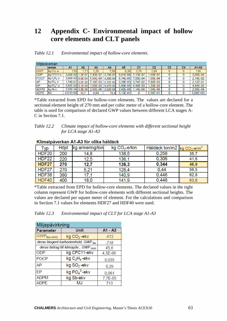
CHALMERS Architecture and Civil Engineering, Master’s Thesis ACEX30 63
12 Appendix C- Environmental impact of hollow core elements and CLT panels
Table 12.1 Environmental impact of hollow-core elements.
*Table extracted from EPD for hollow-core elements. The values are declared for a sectional element height of 270 mm and per cubic meter of a hollow-core element. The table is used for comparison of declared GWP values between different LCA stages A-C in Section 7.1. Table 12.2 Climate impact of hollow-core elements with different sectional height
for LCA stage A1-A3
*Table extracted from EPD for hollow-core elements. The declared values in the right column represent GWP for hollow-core elements with different sectional heights. The values are declared per square meter of element. For the calculations and comparison in Section 7.1 values for elements HDF27 and HDF40 were used. Table 12.3 Environmental impact of CLT for LCA stage A1-A3

CHALMERS, Architecture and Civil Engineering, Master’s Thesis ACEX30 64
*Table extracted from EPD for CLT. The values are declared per cubic meter of the CLT panel. For the calculations and comparison in Section 7.1 declared values for GWP were used.

CHALMERS Architecture and Civil Engineering, Master’s Thesis ACEX30 65
13 Appendix D - Timber connections subjected to shear, axial, and withdrawal loads
Figure 13.1 Connection subjected to shear

CHALMERS, Architecture and Civil Engineering, Master’s Thesis ACEX30 66
Figure 13.2 Connections subjected to axial loads and withdrawal

CHALMERS Architecture and Civil Engineering, Master’s Thesis ACEX30 67
14 Appendix E - Design loads for wall-to-wall connections
Original design: Floor: Hollow-core elements HD/F27 with a thickness of 270 mm.
-* ? 0.344 ���
J� ? 3.37 HIJ� (Appendix C, Table 12.3)
4* ? 2.0 HIJ� (Appendix B, Figure 11.1)
8� ? 0.3 (Appendix B, Figure 11.2)
Scenario 1- removal of corner wall:
2� ? 10.7 m (Distance between the vertical ties)
� ? 7.0 m (Wall element length) The design load for the vertical ties according to equation 4.4: !�O ? D-* E 8� ∙ 4*F ∙ 0.5 ∙ 2� ∙ � ? D3.37 E 0.3 ∙ 2.0F ∙ 0.5 ∙ 10.7 ∙ 7.0 ? 148.68 kN Design load per meter of wall:
!�O� ? 148.68
7.0 ? 21.24 kNm
Required amount of wall shoes SUMO 16H according to Figure 6.5 for this element:
3 ? ���N��
? �7�.���� ? 2.4 → 3 wall shoes
Scenario 2- removal of a façade wall:
2� ? 10.7 m
� ? 7.5 m The design load for the vertical ties according to equation 4.4: !�O ? D-* E 8� ∙ 4*F ∙ 0.5 ∙ 2� ∙ � ? D3.37 E 0.3 ∙ 2.0F ∙ 0.5 ∙ 10.7 ∙ 7.5 ? 159.30 kN Design load per meter of wall:
!�O� ? 159.30
7.5 ? 21.24 kNm

CHALMERS, Architecture and Civil Engineering, Master’s Thesis ACEX30 68
Required amount of wall shoes SUMO 16H according to Figure 6.5 for this element:
3 ? ���N��
? � (.¡)�� ? 2.6 → 3 wall shoes
Proposed solution: Floor: CLT elements with a thickness of 270 mm.
-* ? 108 H¢J� ? 1.06 HI
J� (Appendix B, Figure 11.3)
4* ? 2.0 kNm�
8� ? 0.3
Scenario 1- removal of corner wall:
2� ? 10.7 m
� ? 7.0 m
!�O ? D-* E 8� ∙ 4*F ∙ 0.5 ∙ 2� ∙ � ? D1.06 E 0.3 ∙ 2.0F ∙ 0.5 ∙ 10.7 ∙ 7.0 ? 62.17 kN Design load per meter of wall:
!�O� ? 62.17
7.0 ? 8.90 kNm
Required amount of wall shoes SUMO 16H according to Figure 6.5 for this element:
3 ? ���N��
? ��.���� ? 1.0 → 2 wall shoes
Scenario 2- removal of a façade wall:
2� ? 10.7 m
� ? 7.5 m
!�O ? D-* E 8� ∙ 4*F ∙ 0.5 ∙ 2� ∙ � ? D1.06 E 0.3 ∙ 2.0F ∙ 0.5 ∙ 10.7 ∙ 7.5 ? 66.60 kN Design load per meter of wall:
!�O� ? 66.60
7.5 ? 8.90 kNm
Required amount of wall shoes SUMO 16H according to Figure 6.5 for this element:
3 ? ���N��
? ��.�)�� ? 1.1 → 2 wall shoes

CHALMERS Architecture and Civil Engineering, Master’s Thesis ACEX30 69
15 Appendix F – Material properties of CLT elements, Martinsson’s Trä

CHALMERS, Architecture and Civil Engineering, Master’s Thesis ACEX30 70
16 Appendix G - Design loads for floor-to-wall connection
Design loads applied on angle bracket due to sagging !�O� ? 66.60
7.5 ? 8.90 kNm
-. ? 19.82 0�Z
% ? 1.20Z �� ? D!�O E -.F ∗ % ? 32.18 0�
Figure 16.1 Bending moment equilibrium in angle bracket due to sagging
Dimensions of angle bracket:
6� ? 25 ZZ 2� ? 200ZZ ℎ� ? 70ZZ $� ? 70ZZ
Bending of the angle bracket due to sagging:
3� ? 2
�� ? �� ∗ $�3�
? 1.126 0�Z ? 1126 �Z 3� ? 2
��� ? ��� ? ��3�
? 563.15 �Z

CHALMERS Architecture and Civil Engineering, Master’s Thesis ACEX30 71
� ? 91.58 �Z%^-
9 ? ���� ? 6.15 %^-
Verification of tensile strength in CLT slab due to sagging
Figure 16.2 Tensile load equilibrium of CLT slab due to sagging
! ? ��sinD9F ? 300.4 0�
! ? !���
Where:
��� ? ��� ∗ % ��� ? 3) ∗ 6#�7 ? 4 ∗ 45ZZ ? 180ZZ
��� ? 0.216 Z�
Figure 16.3 Effective cross section of CLT slab parallel to the span direction
bk ? lcsl fg�m ? l. cs nop
&+,),* ? 14 ��x
&+,), ? 0�1 ∗ &+,),*:;
:; ? 1.25 Table 3.2 CLT Handbook (Svensk Trä, 2019)

CHALMERS, Architecture and Civil Engineering, Master’s Thesis ACEX30 72
0�1 ? 1.1 Table 3.3 CLT Handbook (Svensk Trä, 2019)
ij,d,k ? lm. cm nop
bk < ij,d,k Tensile stress induced in slab cross-section will not cause tensile failure in CLT element. Brittle failure is avoided Verification of compressive stresses perpendicular to the grain
"# ? ��3�
? 32.18 0�2 ? 16.09 0�
��� ? $� ∗ 2� ? 0.14 Z�
²³ri ? ²³qp�
? lles fg�m ? l. l� nop
&#,(),* ? 2.0 ��x
i³,sd,k ? f��k ∗ i³,sd,f´n
? l. �� nop
²³ri < i³,sd,k Compressive stresses induced in slab interface with the angle bracket will not cause compressive failure in CLT element. Verification of bolted connection in CLT element against shear failure Dimensions and material properties of the bolts were obtained from Eurocode 3: Design of Steel Structures
µy26 ¶2x··: 4.6
¹vxZ^6^z ? 25 ZZ ? %�
? 200 ��x
= ? 0.3
�� ? <� ∗ &,� ∗ ����:;�
Where:

CHALMERS Architecture and Civil Engineering, Master’s Thesis ACEX30 73
<� ? 0.6 Table 3.4 EN 1993-1-8 &,� ? 240 �/ZZ2 Table 3.1 EN 1993-1-8 :;� ? 1.25 Table 2.1 EN 1993-1-8
���� ? %� ∗ ��� ? 2160 ZZ�
�� ?0.6 ∗ 240 �
ZZ� ∗ 2160 ZZ�
1.25 ? 139 0�
! ? 300.4 0�
~� ? b��
? m. m → c ���j�
The floor-to-wall connection is composed of two angle brackets per slab element, 1.20 m of width. With two angle brackets, the number of bolts required to have an even distribution is four.
Figure 16.4 Distribution of angle brackets, top view