Embed Size (px)
Citation preview
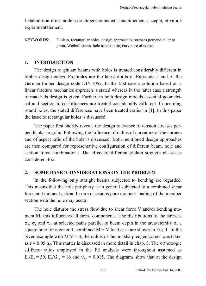
Design of rectangular holes in glulam beams
Otto-Graf-Journal Vol. 14, 2003211
DESIGN OF RECTANGULAR HOLES IN GLULAM BEAMS
BEMESSUNG RECHTECKIGER DURCHBRÜCHE IN BRETT-
SCHICHTHOLZ
DIMENSIONNEMENT DE TROUS RECTANGULAIRES DANS DES
POUTRES EN BOIS LAMELLE COLLE
Lilian Höfflin, Simon Aicher
SUMMARY
The paper deals with rectangular holes in glulam members subjected to
bending. Introductory, the decisive design relevance of the stresses perpendicu-
lar to fiber and beam direction is outlined. Then, exemplarily, the influence of
essential geometric quantities, being – radius of curvature of the corners and as-
pect ratio of the rectangular holes – are revealed. Hereby the stochastic defect
structure of the material glulam is considered, too.
Next, the design approaches according to the drafts of DIN 1052 and EC 5,
differing fundamentally with respect to idealisation of the mechanical problem,
are outlined. The design proposal of DIN 1052 incorporates a classical strength
of materials criterion whereas the EC 5 design model is based on fracture me-
chanics.
A comparison of the two stated design approaches reveals partly extreme
differences of the computational characteristic load capacities. The reason there-
fore results from the different mechanical models and the different recognition
of obviously relevant influencing parameters. A newly granted research project
shall contribute to the elaboration of a unanimously accepted, empirically vali-
dated design model for holes in glulam beams.
ZUSAMMENFASSUNG
Der Beitrag befaßt sich mit rechteckigen Durchbrüchen in biegebean-
spruchten Brettschichtholzträgern. Einführend wird kurz die ausschlaggebende

L. HÖFFLIN, S. AICHER
212
Bemessungsrelevanz der Spannungen rechtwinklig zur Faser- und Trägerrich-
tung dargelegt. Es werden sodann exemplarisch die Einflüsse wesentlicher geo-
metrischer Größen – Ausrundungsradius der Ecken und Seitenverhältnis der
Rechteckdurchbrüche – aufgezeigt. Die stochastische Defektstruktur des Werk-
stoffes Brettschichtholz wird hierbei mitberücksichtigt.
Es folgt eine Darlegung der Bemessungsansätze in den Entwürfen zu DIN
1052 und EC 5, die sich hinsichtlich der Idealisierung des mechanischen Pro-
blems fundamental unterscheiden. Dem Bemessungsvorschlag in DIN 1052 liegt
ein klassisches Höchstspannungskriterium zugrunde während das EC 5 Bemes-
sungsmodell von einem bruchmechanischen Ansatz ausgeht.
Ein Vergleich der genannten Bemessungsvorschriften zeigt zum Teil ex-
treme Unterschiede der rechnerischen charakteristischen Tragfähigkeiten auf,
deren Ursache in den unterschiedlichen mechanischen Modellen und der unter-
schiedlichen Berücksichtigung offensichtlich relevanter Einflußgrößen liegt. Ein
neu bewilligtes Forschungsvorhaben soll dazu beitragen ein allgemein akzep-
tiertes und empirisch abgesichertes Bemessungsmodell für Durchbrüche in
Brettschichtholzträgern zu erarbeiten.
RESUME
On s’intéresse dans cet article à la présence de trous rectangulaires dans des
poutres en lamellé collé sollicitées en flexion, en portant l’attention sur les
contraintes perpendiculaires aux fibres, décisives pour le dimensionnement.
Ainsi, par exemple, l’influence de grandeurs géométriques essentielles – rayon
de courbure des angles et rapport de forme du trou – est mise en évidence.
La nature stochastique des défauts du lamellé collé est également considé-
rée. En s’appuyant sur les règles de dimensionnement relatives aux projets de
normes DIN 1052 et EC5, on obtient des différences fondamentales sur
l’idéalisation du problème mécanique. La proposition émanant de la norme DIN
1052 utilise un critère de résistance des matériaux, alors que le modèle de di-
mensionnement de l’EC5 est basé sur la mécanique de la rupture.
La comparaison des deux approches fait apparaître des différences extrê-
mes sur la capacité portante simulée. La raison provient donc des différents mo-
dèles mécaniques utilisés et d’une prise en compte différente de paramètres dont
l’influence est évidente. Un nouveau projet de recherche financé contribuera à
Design of rectangular holes in glulam beams
Otto-Graf-Journal Vol. 14, 2003213
l’élaboration d’un modèle de dimensionnement unanimement accepté, et validé
expérimentalement.
KEYWORDS: Glulam, rectangular holes, design approaches, stresses perpendicular to
grain, Weibull stress, hole aspect ratio, curvature of corner
1. INTRODUCTION
The design of glulam beams with holes is treated considerably different in
timber design codes. Examples are the latest drafts of Eurocode 5 and of the
German timber design code DIN 1052. In the first case a solution based on a
linear fracture mechanics approach is stated whereas in the latter case a strength
of materials design is given. Further, in both design models essential geometri-
cal and section force influences are treated considerably different. Concerning
round holes, the stated differences have been treated earlier in [1]. In this paper
the issue of rectangular holes is discussed.
The paper first shortly reveals the design relevance of tension stresses per-
pendicular to grain. Following the influence of radius of curvature of the corners
and of aspect ratio of the hole is discussed. Both mentioned design approaches
are then compared for representative configuration of different beam, hole and
section force combinations. The effect of different glulam strength classes is
considered, too.
2. SOME BASIC CONSIDERATIONS ON THE PROBLEM
In the following only straight beams subjected to bending are regarded.
This means that the hole periphery is in general subjected to a combined shear
force and moment action. In rare occasions pure moment loading of the member
section with the hole may occur.
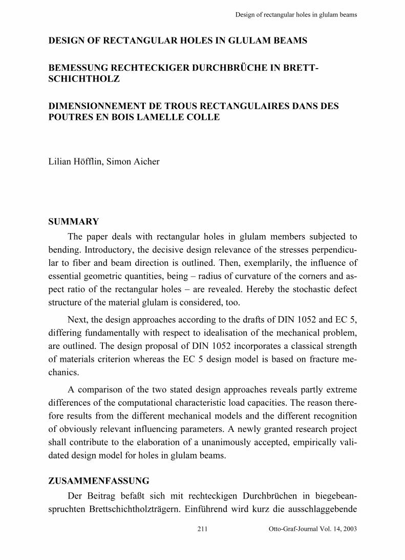
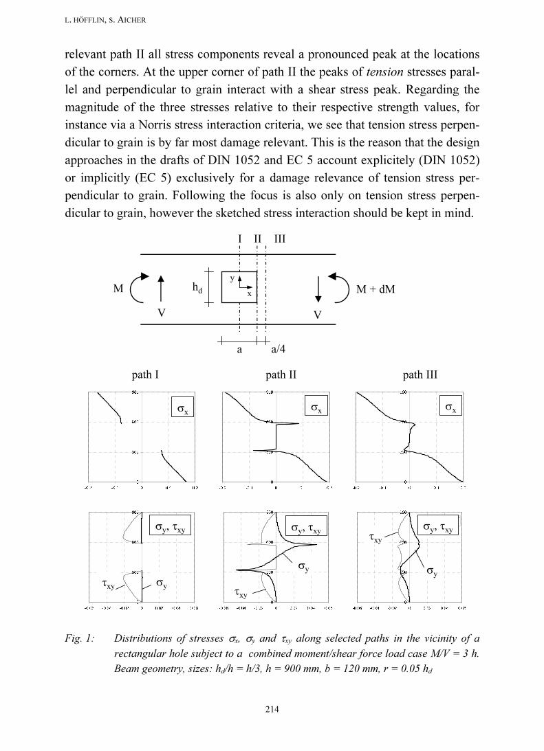
The hole disturbs the stress flow due to shear force V and/or bending mo-
ment M; this influences all stress components. The distributions of the stresses
σx, σy and τxy at selected paths parallel to beam depth in the area/vicinity of a
square hole for a general, combined M + V load case are shown in Fig. 1. In the
given example with M/V = 3, the radius of the not sharp edged corner was taken
as r = 0.05 hd. This matter is discussed in more detail in chap. 3. The orthotropic
stiffness ratios employed in the FE analysis were throughout assumed as
Ex/Ey = 30, Ex/Gxy = 16 and νxy = 0.015. The diagrams show that at the design
L. HÖFFLIN, S. AICHER
214
relevant path II all stress components reveal a pronounced peak at the locations
of the corners. At the upper corner of path II the peaks of tension stresses paral-
lel and perpendicular to grain interact with a shear stress peak. Regarding the
magnitude of the three stresses relative to their respective strength values, for
instance via a Norris stress interaction criteria, we see that tension stress perpen-
dicular to grain is by far most damage relevant. This is the reason that the design
approaches in the drafts of DIN 1052 and EC 5 account explicitely (DIN 1052)
or implicitly (EC 5) exclusively for a damage relevance of tension stress per-
pendicular to grain. Following the focus is also only on tension stress perpen-
dicular to grain, however the sketched stress interaction should be kept in mind.
I II III
V V
M M + dMx
y
hd
a
0
300
600
900
-0.06 -0.04 -0.02 0 0.02 0.04 0.06
Sy, Sxy -Spannungen
SY
SXY
0
300
600
900
-0.06 -0.04 -0.02 0 0.02 0.04 0.06
Sy, Sxy -Spannungen
SXY
SY
0
300
600
900
-0.06 -0.04 -0.02 0 0.02 0.04 0.06
Sy, Sxy -Spannungen
SXY
SY
0
300
600
900
-0.2 -0.1 0 0.1 0.2
Sx -Spannungen
SX
0
300
600
900
-0.2 -0.1 0 0.1 0.2
Sx -Spannungen
SX
0
300
600
900
-0.2 -0.1 0 0.1 0.2
Sx -Spannungen
SX
path I path II path III
σxσxσx
σy, τxy σy, τxyσy, τxy
σyτxy
σy
τxy
σy
τxy
a/4
Fig. 1: Distributions of stresses σx, σy and τxy along selected paths in the vicinity of a
rectangular hole subject to a combined moment/shear force load case M/V = 3 h.
Beam geometry, sizes: hd/h = h/3, h = 900 mm, b = 120 mm, r = 0.05 hd

Design of rectangular holes in glulam beams
Otto-Graf-Journal Vol. 14, 2003215
For assessment of the influences of section forces M and V, considered dif-
ferently in both code drafts, it is advantageous to regard the effect of the load
case pure moment action and the fictive load case “pure” shear force action
separately. A detailed description of the stress computation for the fictive “pure”
V load case is stated in [2].
Due to pure moment action M the stress concentration is located at the ver-
tical edge of the hole (Fig. 2a) whereas due to “pure” shear force action V the
stresses concentrate in the corners of the hole (Fig. 2b). The shapes of the stress
fields for the two load cases are similar to those obtained for round holes [2]. A
combined M+V load case produces an unsymmetrical stress field around the
hole which is a superposition of the two pure load cases.
+ +
+
+
++
a) b)
Fig. 2a, b: Stress distributions perpendicular to grain at the hole periphery for the two
pure load cases
a) pure moment action b) “pure” shear force action
3. EFFECT OF CURVATURE OF THE CORNERS
A crucial matter for rectangular holes are the corners. In case of rectangular
sharp notched corners, i.e. radius of curvature → 0, a stress singularity arises. In
order to avoid this, the corner generally will not be made right-angled but pro-
duced with a curvature 1/r. It is trivial that the maximum stress depends strongly
on the radius. However, for failure initiation due to tension stresses perpendicu-
lar to grain in a brittle material with stochastically distributed defects, the
area/volume, here denoted by Ω, and the shape of the stress distribution σy = σ90
L. HÖFFLIN, S. AICHER
216
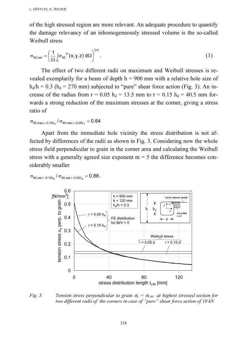
of the high stressed region are more relevant. An adequate procedure to quantify
the damage relevancy of an inhomogeneously stressed volume is the so-called
Weibull stress
m1
m
90wei,90 d)z,y,x(1
∫ Ωσ
Ω=σ
Ω
. (1)
The effect of two different radii on maximum and Weibull stresses is re-
vealed exemplarily for a beam of depth h = 900 mm with a relative hole size of
hd/h = 0.3 (hd = 270 mm) subjected to “pure” shear force action (Fig. 3). An in-
crease of the radius from r = 0.05 hd = 13.5 mm to r = 0.15 hd = 40.5 mm for-
wards a strong reduction of the maximum stresses at the corner, giving a stress
ratio of
64.0/dd 0.05hrmax,90,0.15hrmax,90, =σσ
==
Apart from the immediate hole vicinity the stress distribution is not af-
fected by differences of the radii as shown in Fig. 3. Considering now the whole
stress field perpendicular to grain in the corner area and calculating the Weibull
stress with a generally agreed size exponent m = 5 the difference becomes con-
siderably smaller
88.0/dd 0.05hrwei,90,0.15hrwei,90, =σσ
==.
0
0.1
0.2
0.3
0.4
0.5
0.6
0 40 80 120
stress distribution length lt,90 [mm]
ten
sio
n s
tre
ss σ
y p
erp
. to
gra
in [N/mm
2] h = 900
b = 120
d/h = 0.3
r = 0.05 hd
FE distribution
for M/V = 0
Weibull stress
r = 0.05 d r = 0.15 d
r = 0.15 hd
h = 900 mm
b = 120 mm
hd/h = 0.3
hd
h
highest stressed section
r
integration
area
a
x
y
Fig. 3: Tension stress perpendicular to grain σy = σt,90 at highest stressed section for
two different radii of the corners in case of “pure” shear force action of 10 kN

Design of rectangular holes in glulam beams
Otto-Graf-Journal Vol. 14, 2003217
In the drafts of DIN 1052 and EC 5 the corner radius is equally prescribed
as r ≥ 15 mm, irrespective of hole and beam size. According to the authors’
knowledge, this construction detailing is not bound to any considerations of the
above type and should be analysed appropriately.
4. INFLUENCE OF THE ASPECT RATIO OF THE HOLE
The aspect ratio of the rectangular hole is considered considerably different
in the drafts of DIN 1052 and EC 5. Whereas DIN 1052 does not consider any
influence of the aspect ratio of the hole on load capacity, EC 5 specifies a sig-
nificant load capacity reduction with increasing aspect ratio for same hole depth
hd. Apart thereof, both design codes state equally the following absolute/relative
limits for the dimensions of rectangular holes, being
a ≤ h and hd ≤ 0.4 h
where a and hd are the hole dimensions parallel and normal to beam axis. Thus
the maximum “allowable” aspect ratios reach from
a/hd ≤ 10 for hd/h = 0.1 to
a/hd ≤ 2.5 for hd/h = 0.4.
0
0.1
0.2
0.3
0.4
0.5
0.6
0.7
0.8
0 40 80 120
stress distribution length lt,90 [mm]
ten
sio
n s
tre
ss σ
y p
erp
. to
gra
in
[N/mm2]
a/hd = 1
a/hd = 3
a/hd = 2
a/hd = 1 a/hd = 3a/hd = 2
Weibull stress
FE
distribution
h = 900 mm
b = 120 mm
hd/h = 0.3
r = 0.05 hdhd
h
highest stressed section
r
integration
area
a
x
y
Fig. 4: Tension stress perpendicular to grain σy = σt,90 at highest stressed section acc. to
“pure” shear force action of 10 kN for three different aspect ratios
L. HÖFFLIN, S. AICHER
218
Table 1: Maximum and Weibull stresses for different aspect ratios; also given are the stress
values normalised to the square hole reference case
stress unit
1 2 3
σy ,max N/mm2 0.512 0.628 0.746
σwei N/mm2 0.144 0.170 0.193
σy ,max,n 1) - 1.00 1.23 1.46
σwei,n 1) - 1.00 1.18 1.34
1) normalised to the aspect ratio a/hd = 1
aspect ratio a/hd
The appropriateness of a consideration of the aspect ratio in the design
equations was checked in the frame of this paper exemplarily for the beam con-
figuration, studied before with respect to the influence of the corner radius.
Now, in all cases r = 0.05 hd = 13.5 mm is considered. Additionally to the square
hole aspect ratio of a/hd = 1 regarded in Fig. 3, Fig. 4 specifies the σy stress dis-
tributions for the aspect ratios a/hd = 2 and 3. Table 1 contains the maximum and
Weibull stresses for the different aspect ratios; also given are the stress values
normalised to the square hole reference case. It can be seen that the maximum
stresses increase for the aspect ratios a/hd = 2 and 3 pronouncedly by 23% and
46%, respectively. The Weibull stresses increase slightly less but comparable by
18% and 34%. It is evident, that the aspect ratio should be accounted for in the
design equations.
5. DESIGN OF RECTANGULAR HOLES ACCORDING TO DRAFT
DIN 1052
Following the design for rectangular holes as specified in the revised draft
of the new semi-probabilistic German timber design code [3] is given. The de-
sign model represents a classical strength of materials approach. Hereby the de-
sign tension force perpendicular to grain at the hole periphery, Ft,90,d, is com-
pared to the design value of the resistance Rt,90,d (Rt,90,d not specified explicitly)
1fbl5.0
F
R
F
d,90,t90,t
d,90,t
d,90,t
d,90,t≤= (2a)
where
lt,90 = 0.5 (hd + h) (3)
is the distribution length of the assumed triangular stress distribution perpen-
dicular to grain (see also Fig. 5), b is beam width and ft,90,d is the design tension
Design of rectangular holes in glulam beams
Otto-Graf-Journal Vol. 14, 2003219
strength perpendicular to grain. Rewritten as the ratio of a design stress σt,90,d vs.
design strength ft,90,d , Eq. (2a) reads
1f d,90,t
d,90,t≤
σ where
bl5.0
F
90,t
d,90,t
d,90,t =σ . (2b), ( 4)
The design value of the tension force Ft,90,d is composed of two additive parts
bound to the separate actions of shear force and bending moment
Ft,90,d = Ft,V,d + Ft,M,d (5)
where
Vdd,V,t VF η= and
−=η
2
2
dd
V
h
h3
h
h
4
1(6)
Mdd,M,t MF η= and r
M
h
008.0=η (7)
and Vd, Md absolute values of design shear force and bending moment at the
hole edge1
and
hr = min hrl; hru2 where hrl(ru) ≥ 0.25 h (see also footnote 2). (8)
Further, as already mentioned in chap. 3, the restrictions hd ≤ 0.4 h, a ≤ h and r ≥
15 mm apply.
σt,90 Ft,V
τxy
Vh hd
b
hru
hrl
x
y
lt,90a
r
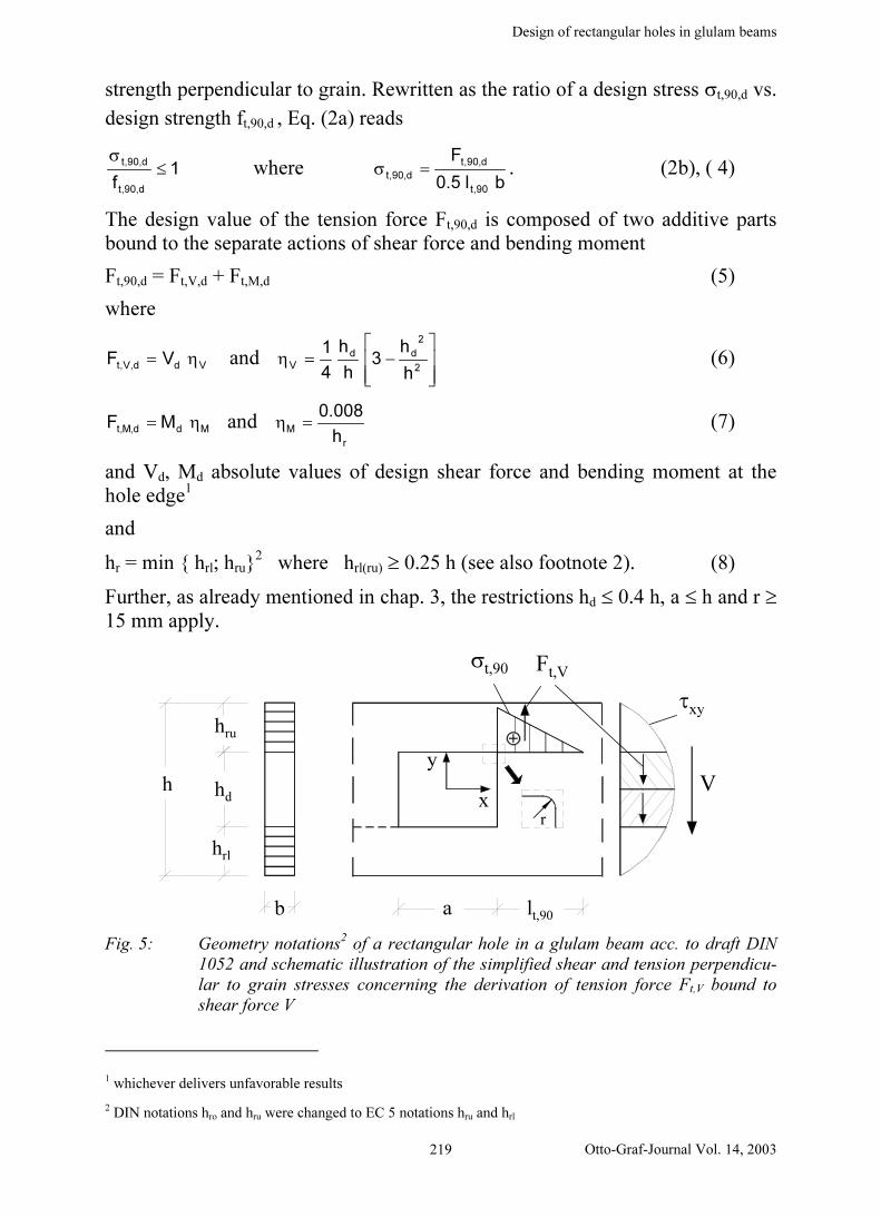
Fig. 5: Geometry notations2 of a rectangular hole in a glulam beam acc. to draft DIN
1052 and schematic illustration of the simplified shear and tension perpendicu-
lar to grain stresses concerning the derivation of tension force Ft,V bound to
shear force V
1 whichever delivers unfavorable results
2 DIN notations hro and hru were changed to EC 5 notations hru and hrl
L. HÖFFLIN, S. AICHER
220
Some comments on the background and limits of the specified equations
seem appropriate (in the following, for sake of simplicity, the subscript d is
omitted, i.e. nominal resp. characteristic values are regarded):
Tension force Ft,V bound to the shear force V, specified in Eq. (6), represents
one half of the resultant of the shear stresses τxy which can not be transferred
in the hole area (see Fig. 5)
V
2/h
0xyV,t VdybF
d
η=∫ τ= ,
−=τ
2
2
xyh
y41
hb
V
2
3(9a,b)
By integration of the stresses perpendicular to grain, as resulting from FE
analysis, it can be shown that Eqs. (6) and (9) deliver the correct stress re-
sultant when the integration is performed over the whole stress distribution
length (including also compression stress areas until the stresses perpendicu-
lar to grain become zero).
Tension force Ft,M bound to the bending moment, specified in Eq. (7), is not
based on analytical or numerical stress analysis but stems from a calibration
to experimental data in different literature sources [4]. The performed cali-
bration procedure can be questioned. A preliminary finite element study for
determination of Ft,M delivered a considerably different result similarly as in
the analogous case of round holes, analysed in [2].
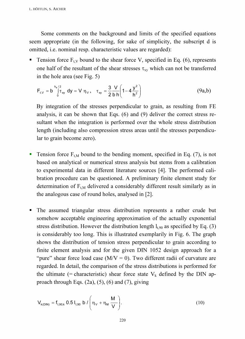
The assumed triangular stress distribution represents a rather crude but
somehow acceptable engineering approximation of the actually exponential
stress distribution. However the distribution length lt,90 as specified by Eq. (3)
is considerably too long. This is illustrated exemplarily in Fig. 6. The graph
shows the distribution of tension stress perpendicular to grain according to
finite element analysis and for the given DIN 1052 design approach for a
“pure” shear force load case (M/V = 0). Two different radii of curvature are
regarded. In detail, the comparison of the stress distributions is performed for
the ultimate (= characteristic) shear force state Vk defined by the DIN ap-
proach through Eqs. (2a), (5), (6) and (7), giving
η+η=
V
M/bl5.0fV MV90,tk,90,t)DIN(k . (10)
Design of rectangular holes in glulam beams
Otto-Graf-Journal Vol. 14, 2003221
With tension strength ft,90,k = 0.5 N/mm2 (constant for all glulam strength
classes according to draft DIN 1052). Eq. (10) delivers Vk(DIN) = 80.5 kN as
input for the FE analysis. It can be seen from the graphs that the nonlinear
stress distribution according to continuum analysis shows a distinctly higher
stress gradient and a much higher stress level closer to the hole periphery and
hence shorter stress distribution lengths lt,90. The maximum stresses accord-
ing to continuum analysis might at first view be considered too high; how-
ever for this judgement, not followed up here, the actually stressed volume
has to be taken into account.
The assumed triangular stress distribution according to DIN 1052 is inde-
pendent from the moment/shear force ratio, what is not corresponding with
numerical solutions.
0
1
2
3
4
5
0 100 200 300 400 500 600
stress distribution length lt,90 [mm]
ten
sio
n s
tre
ss σ
y p
erp
. to
gra
in [N/mm
2] h = 900
b = 120
d/h = 0.3
E DIN 1052 distribution
for all M/V
r = 0.05 d
r = 0.15 d
FE distribution
for "pure" shear
force action
Fig. 6: Tension stress σy perpendicular to grain vs. stress distribution length lt,90 at highest
stressed section for a “pure” shear load action at failure state Vk according to
E DIN 1052 (Vk = 80.5 kN) and according to continuum analysis bound to load
Vk(DIN)
Tension stress/force perpendicular to grain, Ft,90/σt,90, according to E DIN
1052 are equal for square and rectangular holes. However, as shown in chap.
3, the aspect ratio of the hole has an influence on stresses which increase
considerably with aspect ratios a/hd > 1.
L. HÖFFLIN, S. AICHER
222
6. DESIGN OF RECTANGULAR HOLES ACCORDING TO
DRAFT OF EUROCODE 5
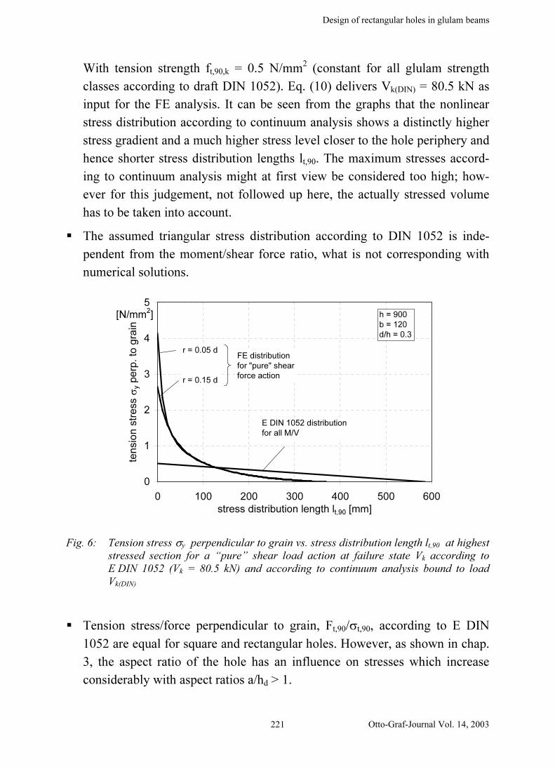
The linear fracture mechanics based strength verification for a glulam beam
with a rectangular hole subjected to design shear force Vd and design moment
Md at the center of the hole is conducted as for a notched beam subjected to a
shear force Vd/2 [5] (see Fig. 7). The effect of the additional moment on the load
capacity is not considered. The design equation formally reads as an approach
based on the comparison of design shear stress τd vs. design shear strength fv,d
which is reduced by a factor kV depending on absolute beam depth and relative
hole size
1fk d,vV
d≤
τ and
ef
d
d
hb
V5.1=τ . (11a, b)
Factor kV is defined by
( )
α−
α+α−α
=
2
*
*
nV
1
h
x8.01h
k
1
mink (12)
where
h* = h/2
x = distance from line of shear force action to the corner = a/2
α = hef/h*
glulamfor
timbersolidfor
5.6
5k
n
=
The relevant constructive restrictions were mentioned in chap. 3.
hrl
hd
hefh
ru
= x
a
a/2
V/2
h/2
h
Fig. 7: Dimensions of rectangular holes in beams and respective approximations for the
notched beam design according to EC 5; leftside: actual geometry; rightside:
notched beam approximation
Design of rectangular holes in glulam beams
Otto-Graf-Journal Vol. 14, 2003223
The following comments on the background and limits of the specific equations
seem appropriate:
The fracture mechanics bound design equation for an end-notched beam is
based on total energy release rate [6]. As fracture mechanism, exclusively
Mode I crack opening was assumed. So the implicitly incorporated basic
material resistance is the characteristic fracture energy Gf,k in tension perpen-
dicular to grain. The formally shear strength based resistance side in Eq.
(11a) is simply the result of an equation multiplication by fv,k/fv,k.
The basic analytical end-notched beam solution was calibrated to experi-
mental results for the end-notched beam case with a factor of 2/3.
Characteristic fracture energy Gf,k was eliminated from the resistance side by
the approximation that
2
k,v
05,90k,f
nf
EG
3
1k = (13)
results approximately in 5 and 6.5 for solid wood and glulam, respectively,
throughout all strength classes.
The design according to EC 5 takes into account the shape of the rectangular
hole. Coinciding with the results in chap. 3, rectangular holes with aspect ra-
tios a/hd > 1 result in reduced kv values.
7. COMPARISON OF LOAD CAPACITIES ACCORDING TO
DRAFTS OF E DIN 1052 AND EC 5
For a quantitative comparison of both design approaches these are evalu-
ated for characteristic shear force with and without consideration of a bending
moment influence. The comparison comprises the following beam, hole sizes
and geometries:
beam depth h: h1 = 450 mm, h2 = 2 h1 = 900 mm and
h3 = 3.33 h1 = 1500 mm
beam width b: b = constant = 120 mm
hole to depth ratio: ranging from 0.1 to 0.4
Another important aspect when comparing the two drafts consists in the
considered glulam strength class. In principle, strength class should have no im-
pact, i.e. both design approaches should agree/disagree similarly for all strength
L. HÖFFLIN, S. AICHER
224
classes. Unfortunately this is not the case, as shear strength fv,k and tension
strength perpendicular to grain ft,90,k, relevant in this context, are not specified
equally for same glulam strength classes in DIN 1052 and EN 1194. (Note: The
latter standard is the European glulam strength class standard to be used in
EC 5.) The differences are shown in Tab. 2. It can be seen that the characteristic
strength values ft,90,k and fv,k according to DIN 1052 remain constant for all glu-
lam strength classes whereas the respective values according to EN 1194 depend
strongly on the glulam strength class. So, the comparison of the design models
for holes in glulam is superimposed by obvious uncertainties on the true strength
properties ft,90,k and fv,k. Therefore the hole design comparison is conducted for
two glulam strength classes, one with rather dissimilar strength values/ratios
(= the low glulam strength class GL 24c) and one with rather similar strength
values in both codes (= the high glulam strength class GL 32h).
Table 2: Characteristic strength values [N/mm2] for glulam of combined (c) and homoge-
neous (h) build-up acc. to European Standard EN 1194 and the German draft
design code DIN 1052
ft,90,k
fv ,k
ft,90,k 0.35 0.40 0.40 0.45 0.45 0.50 0.50 0.60
fv ,k 2.20 2.70 2.70 3.20 3.20 3.80 3.80 4.30EN 1194
DIN 10523.5
GL 24c GL 24h GL 28c GL 28h GL 32c GL 32h GL 36c
0.5
GL 36h
glulam strength classstandard charact.
strength value
First, the computational shear force capacities without consideration of a
bending moment influence (M/V = 0) are regarded. Figures 8a, b show the shear
force capacity Vk depending on the hole to depth ratio hd/h for the 3 different
beam depths as resulting from the EC 5 and DIN 1052 approach. Figure 8a il-
lustrates the case for strength class GL 24c and Fig. 8b refers to GL 32h. A
comparison of the results of the different design approaches reveals in general
considerable discrepancies, discussed below in more detail.
Regarding strength class GL 24c (Fig. 8a), the two design approaches re-
veal similar characteristic shear force capacities for small beams (here: h = 450
mm). However, with increasing beam depth the shear force capacities differ ex-
tremely. This is an immediate consequence of the different recognition of the
depth effect in the linear fracture mechanics approach (EC 5) and in the strength

Design of rectangular holes in glulam beams
Otto-Graf-Journal Vol. 14, 2003225
0
50
100
150
200
250
300
350
0 0.1 0.2 0.3 0.4 0.5
hole to depth ratio hd/h
sh
ea
r fo
rce
ca
pa
city V
k [
kN
] EC 5
DIN 1052 (M/V = 0)
h1 = 450
h2 = 900
h3 = 1500
a)
0
50
100
150
200
250
300
350
0 0.1 0.2 0.3 0.4 0.5
hole to depth ratio hd/h
sh
ea
r fo
rce
ca
pa
city V
k [
kN
] EC 5
DIN 1052 (M/V = 0)
h1 = 450
h2 = 900
h3 = 1500
b)
Fig. 8a, b: Characteristic shear force capacity of glulam beams with a square hole without
consideration of a bending moment influence according to drafts of EC 5 and
DIN 1052 depending on the hole to depth ratio and on the beam depth
a) for glulam strength class GL 24c
b) for glulam strength class GL 32h
0
40
80
120
160
200
240
0 0.1 0.2 0.3 0.4 0.5
hole to depth ratio hd/h
sh
ea
r fo
rce
ca
pa
city V
k [
kN
]
E DIN 1052
EC 5
0
1h
10h
5h
2.5h
h = 900 mm
b = 120 mm
GL 24c
M/V =
a)
0
40
80
120
160
200
240
0 0.1 0.2 0.3 0.4 0.5
hole to depth ratio hd/h
sh
ea
r fo
rce
ca
pa
city V
k [kN
]
E DIN 1052
EC 5
0
1h
10h
5h
2.5h
h = 900 mm
b = 120 mm
GL 32h
M/V =
b)
Fig. 9a, b: Characteristic shear force capacity of a glulam beam with a square hole de-
pending on the hole to depth ratio for different moment shear force ratios M/V
according to drafts of EC 5 and DIN 1052
a) for glulam strength class GL 24c
b) for glulam strength class GL 32h
L. HÖFFLIN, S. AICHER
226
of materials approach (DIN 1052), respectively. In the first case, load capacities
increase proportional to h and in the second case proportional to h.
Regarding strength class GL 32h (Fig. 8b) the characteristic shear force ca-
pacities according to EC 5 increase by the ratio of characteristic shear strengths
3.8/2.2 = 1.7 vs. the results specified for GL 24c whereas the values according to
DIN 1052 do not change. Consequently, now the predicted load capacities differ
strongly for small beams whereas for medium sized beam depths throughout a
rather good agreement can be stated. This is also true for large beams when re-
garding medium sized holes (hd/h ≈ 0.15 – 0.25).
Figures 9a, b show the shear force capacity for both design approaches,
now considering the influence of a bending moment, too. In detail the results are
given for a medium sized beam (h2 = 900 mm) for the glulam strength classes
GL 24c and GL 32h. The parametric dependency of the DIN solution on the
section force ratio M/V is specified for the realistic range of M/V = 0 to 10 h.
Ratios M/V of up to about 2.5 h relate to holes very close to the supports, the
larger ratios increasingly mirror constructions with holes closer to mid-span. It
can be taken from the graph that the additional incorporation of the bending
moment influence results in a tremendous reduction of the load capacity of the
beam according to DIN 1052 as compared to the EC 5 approach.
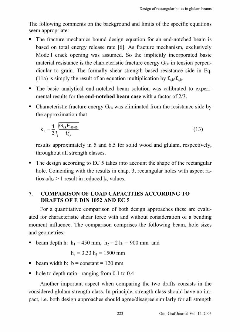
Finally, the differences of both design codes concerning aspect ratio of the
hole are quantified. As stated, DIN 1052 does not account explicitly for the as-
pect ratio of the hole. (Note: Implicitly the effect is considered in some way, as
the design section forces in DIN 1052 are to be evaluated for the vertical edges
of the hole what includes aspect ratio on the action side.) Contrary, EC 5 incor-
porates an expressed influence of the aspect ratio on the resistance side. The ef-
fect is depicted in Fig. 10 as the ratio of shear force capacity of a rectangular
hole with aspect ratio a/hd > 1 vs. a square hole with a/hd = 1. The ratio is given
for different hole to depth ratios hd/h. Further the specified constructive limits
a ≤ h and hd/h ≤ 0.4 are accounted for.
The graph reveals a marked capacity reduction with increasing aspect ra-
tios. So for example, for a realistic hole geometry with a hole to depth ratio of
hd/h = 0.3 and an aspect ratio of a/hd = 3, the shear force capacity drops by 40%
vs. the square hole. This strength reduction may be compared with the results of
the continuum calculation on the influence of aspect ratio in chap. 4. There, the
Design of rectangular holes in glulam beams
Otto-Graf-Journal Vol. 14, 2003227
0
0.2
0.4
0.6
0.8
1
0 0.1 0.2 0.3 0.4 0.5
hole to depth ratio hd/h
red
uctio
n o
f th
e s
he
ar
forc
e c
ap
acity
a/hd = 1
1.5
2
2.5
33.54
568
10
a ≤ h
Fig. 10: Influence of the aspect ratio a/hd on shear force capacity acc. to draft EC 5
studied example delivered for the same hole geometry shows increases of
maximum and Weibull stresses of 1.46 and 1.34, respectively. Assuming a usual
strength of materials criterion, the load capacity reduction vs. the square hole
case would be 32% and 25%, respectively. This confirms very roughly the order
of magnitude indicated by the EC 5 approach, which probably delivers a too
conservative estimate of the influence of the aspect ratio.
8. CONCLUSIONS
A comparison of the design approaches in DIN 1052 and EC 5 for rectan-
gular holes in glulam beams revealed strong discrepancies in many aspects. The
design approaches which are based on fundamentally different mechanical mod-
els differ not only in the predicted load capacities, being very unsatisfactory
from a safety point of view, but also in a different recognition of essential pa-
rameters. Important influences which should be accounted for, are:
size effect (generally acknowledged in tension perpendicular to grain
problems)
moment to shear force ratio
hole to depth ratio
aspect ratio of the hole
model invariance vs. different glulam strength classes

L. HÖFFLIN, S. AICHER
228
The two design approaches account for the above mentioned parameters as fol-
lowing:
A size effect is considered in EC 5 but not in DIN 1052. The EC 5
model incorporates a depth influence according to linear fracture me-
chanics with the factor h .
The moment to shear force ratio is considered in DIN 1052 but not in
EC 5. However, the magnitude of the M influence according to DIN
1052 does not agree with results from FE analysis.
Both design approaches describe the influence of the hole to depth ratio
similar for the “pure” shear force case.
The aspect ratio of the hole is taken into account in EC 5 but not in
DIN 1052. It was confirmed in this paper that a correct model should
consider this influence.
The agreement/disagreement of both design models depends strongly on
the specifically regarded glulam strength class as the design relevant
strength values are specified different in the respective codes/supple-
mentary standards.
In view of the multiplicity of important design parameters and of the
strength variability of the material glulam, it is obvious that an improved, com-
monly agreed model needs a substantial experimental data base for design equa-
tion calibration. The discussed aspects are followed up in a ongoing research
project at Otto-Graf-Institute.
ACKNOWLEDGEMENTS
The authors want to express sincere thanks to Patrick Castera, Head of La-
boratoire du Bois de Bordeaux (LRBB), for his repeated favour in performing
the translation of the French abstract.
The funding of basic aspects of damage evolution at the periphery of holes
in glulam beams by Deutsche Forschungsgemeinschaft via grants to SFB 381
and hereby to subproject A8 “Damage and NDT of the natural fibre composite
material wood ” is thankfully acknowledged.
Design of rectangular holes in glulam beams
Otto-Graf-Journal Vol. 14, 2003229
The authors are grateful to German Institute for Building Technique
(DIBt), Berlin, for a recently granted funding of a research project on design of
holes in glulam beams.
REFERENCES
[1] AICHER, S., HÖFFLIN, L.: Glulam beams with round holes – a comparison
of different design approaches vs. test data. Proceedings CIB-W18 meet-
ing 35, paper CIB-W18/35-12-1, Kyoto, 2002
[2] AICHER, S., HÖFFLIN, L.: Runde Durchbrüche in Biegeträgern aus
Brettschichtholz. Teil 1: Berechnung. Bautechnik 78/10, S. 706-715, 2001
[3] DIN 1052: Design of timber structures – General rules and rules for
buildings. Draft version E DIN 1052 : 2000-05
[4] KOLB, H., EPPLE, A.: Verstärkung von durchbrochenen Brettschicht-
bindern. Forschungsbericht Forschungs- und Materialprüfungsanstalt Ba-
den-Württemberg, Otto-Graf-Institut, Stuttgart, 1985
[5] EUROCODE 5: Design of timber structures – Part 1-1; General rules and
rules for buildings. Final draft prEN 1995-1-1, CEN/TC 250/SC5 N173
[6] GUSTAFSSON, P. J.: A study of strength of notched beams. Proceedings
CIB-W18 Meeting 21, paper CIB-W18A/21-10-1, Vancouver Island,
1988
L. HÖFFLIN, S. AICHER
230


![Special Members Beams with holes and notches...Special Members –Beams with holes and notches slide 13 Stress State –Beam with a hole –pure M Z Y X Axial Stresses y,+ [MPa] 8.0](https://img.pdfslide.net/doc/110x75/610788a81f2f843856363428/special-members-beams-with-holes-and-special-members-abeams-with-holes-and.jpg)