Embed Size (px)
Citation preview
Design of retinal projection displays enabling vision correction
CHAO PING CHEN,* LEI ZHOU, JIAHAO GE, YUHANG WU, LANTIAN MI, YISHI
WU, BING YU, AND YANG LI
Smart Display Lab, Department of Electronic Engineering, Shanghai Jiao Tong University, Shanghai, China *[email protected]
Abstract: We propose a retinal-projection-based near-eye display that is able to merge with the vision correction for myopia. Our solution is highlighted by a corrective lens coated with an array of tiled organic light-emitting diodes and a transmissive spatial light modulator. Its design rules are set forth in detail, followed by the results and discussion regarding the field of view, modulation transfer function, contrast ratio, distortion, and simulated imaging. © 2017 Optical Society of America under the terms of the OSA Open Access Publishing Agreement
OCIS codes: (220.2740) Geometric optical design; (120.2820) Heads-up displays; (120.2040) Displays; (330.3795) Low-vision optics.
References and links
1. Wikipedia, “Augmented reality,” https://en.wikipedia.org/wiki/augmented_reality.2. Wikipedia, “Game of thrones,” https://en.wikipedia.org/wiki/game_of_thrones. 3. H.-S. Chen, Y.-J. Wang, P.-J. Chen, and Y.-H. Lin, “Electrically adjustable location of a projected image in
augmented reality via a liquid-crystal lens,” Opt. Express 23(22), 28154–28162 (2015).4. Q. Gao, J. Liu, J. Han, and X. Li, “Monocular 3D see-through head-mounted display via complex amplitude
modulation,” Opt. Express 24(15), 17372–17383 (2016).5. Q. Gao, J. Liu, X. Duan, T. Zhao, X. Li, and P. Liu, “Compact see-through 3D head-mounted display based on
wavefront modulation with holographic grating filter,” Opt. Express 25(7), 8412–8424 (2017).6. J. P. Rolland, “Wide-angle, off-axis, see-through head-mounted display,” Opt. Eng. 39(7), 1760–1767 (2000). 7. S. Liu, H. Hua, and D. Cheng, “A novel prototype for an optical see-through head-mounted display with
addressable focus cues,” IEEE Trans. Vis. Comput. Graph. 16(3), 381–393 (2010).8. R. Zhu, G. Tan, J. Yuan, and S.-T. Wu, “Functional reflective polarizer for augmented reality and color vision
deficiency,” Opt. Express 24(5), 5431–5441 (2016).9. Y. Amitai, S. Reinhorn, and A. A. Friesem, “Visor-display design based on planar holographic optics,” Appl.
Opt. 34(8), 1352–1356 (1995).10. Y. Amitai, “Extremely compact high-performance HMDs based on substrate-guided optical element,” in SID
Symposium (2004), pp. 310–313.11. H. Mukawa, K. Akutsu, I. Matsumura, S. Nakano, T. Yoshida, M. Kuwahara, and K. Aiki, “A full-color eyewear
display using planar waveguides with reflection volume holograms,” J. Soc. Inf. Disp. 17(3), 185–193 (2009).12. D. Cheng, Y. Wang, H. Hua, and M. M. Talha, “Design of an optical see-through head-mounted display with a
low f-number and large field of view using a freeform prism,” Appl. Opt. 48(14), 2655–2668 (2009).13. Q. Wang, D. Cheng, Y. Wang, H. Hua, and G. Jin, “Design, tolerance, and fabrication of an optical see-through
head-mounted display with free-form surface elements,” Appl. Opt. 52(7), C88–C99 (2013).14. X. Hu and H. Hua, “High-resolution optical see-through multi-focal-plane head-mounted display using freeform
optics,” Opt. Express 22(11), 13896–13903 (2014).15. O. Cakmakci and J. Rolland, “Head-worn displays: a review,” J. Disp. Technol. 2(3), 199–216 (2006). 16. S. C. McQuaide, E. J. Seibel, J. P. Kelly, B. T. Schowengerdt, and T. A. Furness III, “A retinal scanning display
system that produces multiple focal planes with a deformable membrane mirror,” Displays 24(2), 65–72 (2003).17. A. Maimone, D. Lanman, K. Rathinavel, K. Keller, D. Luebke, and H. Fuchs, “Pinlight displays: wide field of
view augmented reality eyeglasses using defocused point light sources,” ACM Trans. Graph. 33(4), 89 (2014). 18. M. Sugawara, M. Suzuki, and N. Miyauchi, “Retinal imaging laser eyewear with focus-free and augmented
reality,” in SID Display Week (2016), pp. 164–167.19. C. P. Chen, Z. Zhang, and X. Yang, “A head-mounted smart display device for augmented reality,” CN Patent
201610075988.7 (2016). 20. L. Zhou, C. P. Chen, Y. Wu, K. Wang, and Z. Zhang, “See-through near-eye displays for visual impairment,” in
The 23rd International Display Workshops in conjunction with Asia Display (2016), pp. 1114–1115.21. L. Zhou, C. P. Chen, Y. Wu, Z. Zhang, K. Wang, B. Yu, and Y. Li, “See-through near-eye displays enabling
vision correction,” Opt. Express 25(3), 2130–2142 (2017).
Vol. 25, No. 23 | 13 Nov 2017 | OPTICS EXPRESS 28223
#307688 https://doi.org/10.1364/OE.25.028223 Journal © 2017 Received 21 Sep 2017; revised 25 Oct 2017; accepted 25 Oct 2017; published 30 Oct 2017
22. C. P. Chen, Y. Wu, and L. Zhou, “An optical display device for augmented reality,” CN Patent 201610112824.7(2016).
23. Y. Wu, C. P. Chen, L. Zhou, Y. Li, B. Yu, and H. Jin, “Design of see-through near-eye display for presbyopia,” Opt. Express 25(8), 8937–8949 (2017).
24. Y. Wu, C. P. Chen, L. Zhou, Y. Li, B. Yu, and H. Jin, “Near-eye display for vision correction with large FOV,” in SID Display Week (2017), pp. 767–770.
25. C. Chen, H. Li, Y. Zhang, C. Moon, W. Y. Kim, and C. G. Jhun, “Thin-film encapsulation for top-emittingorganic light-emitting diode with inverted structure,” Chin. Opt. Lett. 12(2), 022301 (2014).
26. Wikipedia, “Human eye,” https://en.wikipedia.org/wiki/human_eye.27. Wikipedia, “Cornea,” https://en.wikipedia.org/wiki/cornea.28. University of Notre Dame, “Physics of the eye,” https://www3.nd.edu/~nsl/Lectures/mphysics.29. F. L. Pedrotti, L. M. Pedrotti, and L. S. Pedrotti, Introduction to Optics, 3rd ed. (Addison-Wesley, 2006).30. Y.-J. Wang, P.-J. Chen, X. Liang, and Y.-H. Lin, “Augmented reality with image registration, vision correction
and sunlight readability via liquid crystal devices,” Sci. Rep. 7(1), 433 (2017).31. H. K. Walker, W. D. Hall, and J. W. Hurst, Clinical Methods: The History, Physical and Laboratory
Examinations 3rd Edition (Butterworth-Heinemann, 1990), Chap. 58.32. E. Lueder, Liquid Crystal Displays: Addressing Schemes and Electro-Optical Effects, 2nd ed. (Wiley, 2010).33. X. Shi, J. Wang, J. Liu, S. Huang, X. Wu, C. Chen, J. Lu, Y. Su, Y. Zheng, W. Y. Kim, and G. He, “High-
performance green phosphorescent top-emitting organic light-emitting diodes based on FDTD optical simulation,” Org. Electron. 15(4), 864–870 (2014).
34. S. D. Brotherton, Introduction to Thin Film Transistors: Physics and Technology of TFTs (Springer, 2013). 35. J. Cao, J.-W. Xie, X. Wei, J. Zhou, C.-P. Chen, Z.-X. Wang, and C. Jhun, “Bright hybrid white light-emitting
quantum dot device with direct charge injection into quantum dot,” Chin. Phys. B 25(12), 128502 (2016).36. C. P. Chen, Y. Li, Y. Su, G. He, J. Lu, and L. Qian, “Transmissive interferometric display with single-layer
Fabry-Pérot filter,” J. Disp. Technol. 11(9), 715–719 (2015).37. R. E. Fischer, B. Tadic-Galeb, and P. R. Yoder, Optical System Design, 2nd ed. (McGraw-Hill Education, 2008). 38. B. Brown, The Low Vision Handbook for Eyecare Professionals, 2nd ed. (Slack Inc., 2007). 39. H. H. Hopkins, “The numerical evaluation of the frequency response of optical systems,” Proc. Phys. Soc. B
70(10), 1002–1005 (1957).
1. Introduction
It has been almost three decades since the term “augmented reality (AR)” was coined at Boeing in 1990 by Thomas Caudell [1]. Today, AR is undergoing a season that might be called “game of thrones” [2] as there are a host of AR players or technologies being active and seemingly promising but none of them is predominant. Among other things, the solution for a see-through near-eye display (NED) that would perfectly live up to the AR standards is still an open question. As far as the cost of fabrication is concerned, combiner-based NEDs, which rely on either beam splitters [3–5] or semi-reflective mirrors [6–8], are preferred. However, due to the size of beam splitters and semi-reflective mirrors, such NEDs―if designed with a large field of view (FOV)―are often bulky and heavy. As far as the form factor is concerned, waveguide-based NEDs, including both planar [9–11] and freeform [12–14] waveguides, are favorable as the optical path can be compressed into the waveguide.However, once the light enters into a waveguide, the maximum angle, at which it could leave,will be bound by the total internal reflection and the ways of out-coupling. For this reason,FOVs of such NEDs are usually below 50° [15]. As far as FOV is concerned, retinal-projection-based NEDs [16–18] are unparalleled by the former two. For example, pinlightdisplay [17], co-developed by University of North Carolina at Chapel Hill and Nvidia,achieved 110° FOV on a very simple structure that merely comprises a plastic substrateetched with V-shaped notches and a transmissive spatial light modulator (SLM).
For wearable NEDs, optics aside, ergonomics needs to be taken into account as well. One of the ergonomic pain points to solve is to save the visually impaired users from the trouble of wearing extra eyeglasses or contact lens. As earlier attempts, we introduced both combiner-based [19–21] and waveguide-based [22–24] NEDs, which are merged with the prescription or corrective lenses for vision correction. In this paper, a retinal-projection-based NED―we shall refer to it as retinal projection display (RPD) hereafter―that enables vision correction is proposed. In what follows, its structure, design rules and simulation results are to be elaborated.
Vol. 25, No. 23 | 13 Nov 2017 | OPTICS EXPRESS 28224
2. Design principle
2.1 Proposed structure
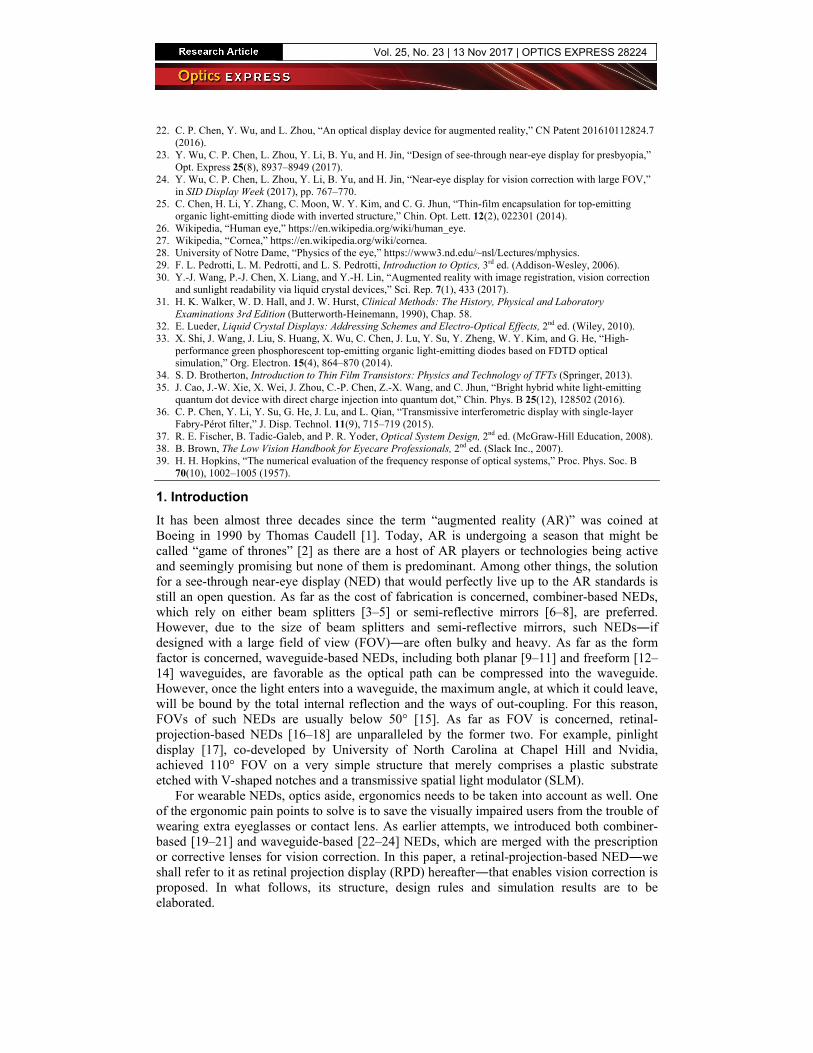
Figure 1 is the schematic drawing of the proposed RPD, which involves four major components, i.e. a corrective lens, an array of organic light-emitting diodes (OLEDs) [25], a transmissive SLM, and an eye. The corrective lens is used for compensating the refractive anomalies of the eye, say myopia. Preferably, its outer surface is concave, while its inner surface is flat, upon which OLEDs can be easily fabricated or laminated. OLEDs serve as the light source to illuminate the virtual image. Since the size of an individual OLED is way smaller than that of SLM, each OLED can be regarded as a point light source. The SLM is used for generating virtual images. ds is the distance between the SLM and eye. dc is the distance between the corrective lens and eye. D is the center spacing between two adjacent OLEDs. L is the dimension of SLM.
ds
L
dc
SLM
Corrective lens
D
EyeOLED
Fig. 1. Schematic drawing of the proposed RPD. ds is the distance between the SLM and eye. dc is the distance between the corrective lens and eye. D is the center spacing between two adjacent OLEDs. L is the dimension of SLM.
2.2 Eye
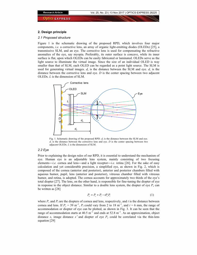
Prior to explaining the design rules of our RPD, it is essential to understand the mechanism of eye. Human eye is an adjustable lens system, mainly consisting of two focusing elements―i.e. cornea and lens―and a light receptor―i.e. retina [26]. For the sake of easy calculation and yet considerable precision, a simplified eye, as shown in Fig. 2, which is composed of the cornea (anterior and posterior), anterior and posterior chambers filled with aqueous humor, pupil, lens (anterior and posterior), vitreous chamber filled with vitreous humor, and retina, is adopted. The cornea accounts for approximately two thirds of the eye’s total diopter [27]. The lens, on the other hand, is responsible for fine-tuning the diopter of eye in response to the object distance. Similar to a double lens system, the diopter of eye Pe can be written as [28]
c l c leP P P tP P= + − (1)
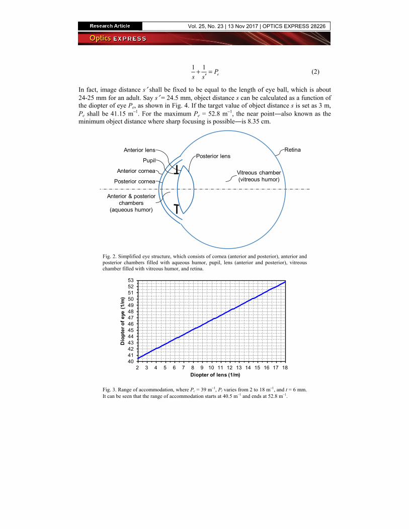
where Pc and Pl are the diopters of cornea and lens, respectively, and t is the distance between cornea and lens. If Pc = 39 m−1, Pl could vary from 2 to 18 m−1, and t = 6 mm, the range of accommodation or diopter of eye can be plotted, as shown in Fig. 3. It can be seen that the range of accommodation starts at 40.5 m−1 and ends at 52.8 m−1. As an approximation, object distance s, image distance s′ and diopter of eye Pe could be correlated via the thin-lens equation [29]
Vol. 25, No. 23 | 13 Nov 2017 | OPTICS EXPRESS 28225
1 1eP
s s′+ = (2)
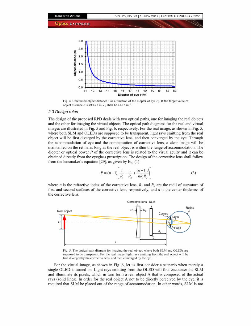
In fact, image distance s′ shall be fixed to be equal to the length of eye ball, which is about 24-25 mm for an adult. Say s′ = 24.5 mm, object distance s can be calculated as a function ofthe diopter of eye Pe, as shown in Fig. 4. If the target value of object distance s is set as 3 m,Pe shall be 41.15 m−1. For the maximum Pe = 52.8 m−1, the near point―also known as theminimum object distance where sharp focusing is possible―is 8.35 cm.
Anterior cornea
Posterior cornea
Anterior lensPosterior lens
Pupil
Retina
Anterior & posterior chambers
(aqueous humor)
Vitreous chamber (vitreous humor)
Fig. 2. Simplified eye structure, which consists of cornea (anterior and posterior), anterior and posterior chambers filled with aqueous humor, pupil, lens (anterior and posterior), vitreous chamber filled with vitreous humor, and retina.
4041424344454647484950515253
2 3 4 5 6 7 8 9 10 11 12 13 14 15 16 17 18
Dio
pte
r o
f e
ye (
1/m
)
Diopter of lens (1/m)
Fig. 3. Range of accommodation, where Pc = 39 m−1, Pl varies from 2 to 18 m−1, and t = 6 mm. It can be seen that the range of accommodation starts at 40.5 m−1 and ends at 52.8 m−1.
Vol. 25, No. 23 | 13 Nov 2017 | OPTICS EXPRESS 28226
0.0
0.5
1.0
1.5
2.0
2.5
3.0
41 42 43 44 45 46 47 48 49 50 51 52 53
Obj
ect d
ista
nce
(m)
Diopter of eye (1/m)
Fig. 4. Calculated object distance s as a function of the diopter of eye Pe. If the target value of object distance s is set as 3 m, Pe shall be 41.15 m−1.
2.3 Design rules
The design of the proposed RPD deals with two optical paths, one for imaging the real objects and the other for imaging the virtual objects. The optical path diagrams for the real and virtual images are illustrated in Fig. 5 and Fig. 6, respectively. For the real image, as shown in Fig. 5, where both SLM and OLEDs are supposed to be transparent, light rays emitting from the real object will be first diverged by the corrective lens, and then converged by the eye. Through the accommodation of eye and the compensation of corrective lens, a clear image will be maintained on the retina as long as the real object is within the range of accommodation. The diopter or optical power P of the corrective lens is related to the visual acuity and it can be obtained directly from the eyeglass prescription. The design of the corrective lens shall follow from the lensmaker’s equation [29], as given by Eq. (1)
1 2 1 2
1 1 ( 1)( 1)
n dP n
R R nR R
−= − − +
(3)
where n is the refractive index of the corrective lens, R1 and R2 are the radii of curvature of first and second surfaces of the corrective lens, respectively, and d is the center thickness of the corrective lens.
Corrective lens
Lens
Real object
SLM
Retina
s
R1
O
R2
ds
dc
Pupil
ap
Cornea
Fig. 5. The optical path diagram for imaging the real object, where both SLM and OLEDs are supposed to be transparent. For the real image, light rays emitting from the real object will be first diverged by the corrective lens, and then converged by the eye.
For the virtual image, as shown in Fig. 6, let us first consider a scenario when merely a single OLED is turned on. Light rays emitting from the OLED will first encounter the SLM and illuminate its pixels, which in turn form a real object A that is composed of the actual rays (solid lines). In order for the real object A not to be directly perceived by the eye, it is required that SLM be placed out of the range of accommodation. In other words, SLM is too
Vol. 25, No. 23 | 13 Nov 2017 | OPTICS EXPRESS 28227
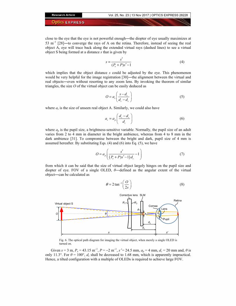
close to the eye that the eye is not powerful enough―the diopter of eye usually maximizes at 53 m−1 [28]―to converge the rays of A on the retina. Therefore, instead of seeing the real object A, eye will trace back along the extended virtual rays (dashed lines) to see a virtual object S being formed at a distance s that is given by
( ) 1e
ss
P P s=
+ ′ −′
(4)
which implies that the object distance s could be adjusted by the eye. This phenomenon would be very helpful for the image registration [30]―the alignment between the virtual and real objects―even without resorting to any zoom lens. By invoking the theorem of similar triangles, the size O of the virtual object can be easily deduced as
cs
c s
s dO a
d d
−= −
(5)
where as is the size of unseen real object A. Similarly, we could also have
c ss p
c
d da a
d
−=
(6)
where ap is the pupil size, a brightness-sensitive variable. Normally, the pupil size of an adult varies from 2 to 4 mm in diameter in the bright ambience, whereas from 4 to 8 mm in the dark ambience [31]. To compromise between the bright and dark, pupil size of 4 mm is assumed hereafter. By substituting Eqs. (4) and (6) into Eq. (5), we have
( )1
) 1pe c
sO a
P P s d
= − + −
′′
(7)
from which it can be said that the size of virtual object largely hinges on the pupil size and diopter of eye. FOV of a single OLED, θ―defined as the angular extent of the virtual object―can be calculated as
12 tan2
O
sθ − =
(8)
Corrective lens
Lens
SLM
RetinaR1 R2
apθ as
AO
s
dc
s′
Pupil
Cornea
ds
Virtual object S
Fig. 6. The optical path diagram for imaging the virtual object, when merely a single OLED is turned on.
Given s = 3 m, Pe = 43.15 m−1, P = −2 m−1, s′ = 24.5 mm, ap = 4 mm, dc = 20 mm and, θ is only 11.3°. For θ = 100°, dc shall be decreased to 1.68 mm, which is apparently impractical. Hence, a tilted configuration with a multiple of OLEDs is required to achieve large FOV.
Vol. 25, No. 23 | 13 Nov 2017 | OPTICS EXPRESS 28228

Now consider a scenario when two adjacent OLEDs are simultaneously turned on, as illustrated in Fig. 7. There will be two virtual objects being imaged at the distance s. In order for these two virtual objects to be seamlessly tiled, the centers of two adjacent OLEDs should be spaced at an optimal distance D that is given by [17]
1 cp
dD a
s = −
(9)
In addition, for the above condition to be strictly met, the distance ds between the SLM and eye should be adjusted as
p cs
p
a dd
a D=
+(10)
Corrective lens
Lens
SLM
RetinaR1
O
R2
ap
Virtual objects
D
Pupil
Cornea
s
dc
ds
Fig. 7. The optical path diagrams for imaging multiple virtual objects, when two adjacent OLEDs are simultaneously turned on.
As can be inferred from Eq. (9), the optimal distance D will be subject to change as both pupil and diopter of eye may vary from time to time. When pupil expands or shrinks, shifting the pupil size away from the predetermined value, there will be an overlapping or gap between the neighboring virtual objects. To handle the change in pupil size, the array of tiled OLEDs shall be addressed in a way that it is able to dynamically tune the distance D to match with the current pupil size [17]. Since the distance dc is usually way smaller than the object distance s, the change in diopter of eye, on the other hand, barely affects the distance D unless the object distance s becomes very close.
2.4 Field of view
FOV is a key indicator for evaluating the performance of RPD. Referring to Fig. 8, FOV of the real image, FOVr―defined as the angular extent of the corrective lens―can be calculated as
2 212 tan
2rc
W HFOV
d− + =
(11)
where W and H represent the horizontal and vertical dimensions of the corrective lens, respectively. It can be seen that FOVr is limited by the size of corrective lens and it would become larger as the eye gets closer to the corrective lens. On the other hand, FOV of the virtual image, FOVv, is defined as the angular extent of the SLM―if SLM is fully illuminated and smaller than the corrective lens―which be estimated by
12 tan2v
s
LFOV
d−
=
(12)
Vol. 25, No. 23 | 13 Nov 2017 | OPTICS EXPRESS 28229
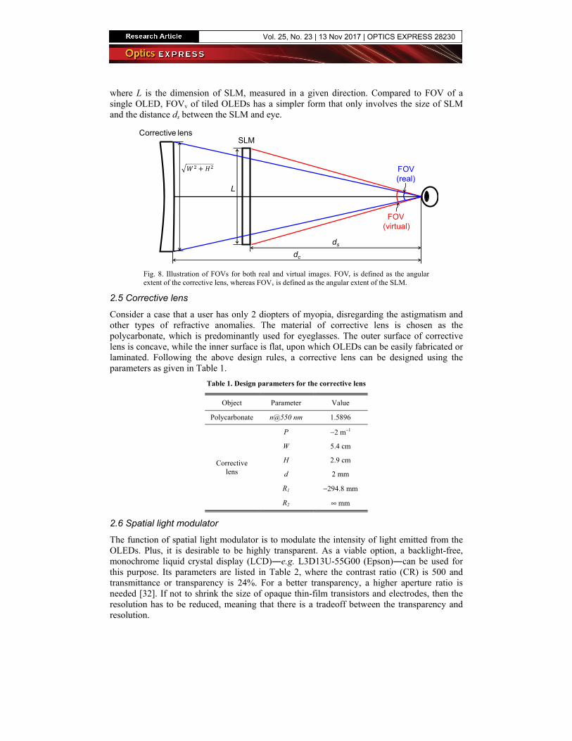
where L is the dimension of SLM, measured in a given direction. Compared to FOV of a single OLED, FOVv of tiled OLEDs has a simpler form that only involves the size of SLM and the distance ds between the SLM and eye.
SLMCorrective lens
FOV (real)
FOV (virtual)
L
ds
dc
Fig. 8. Illustration of FOVs for both real and virtual images. FOVr is defined as the angular extent of the corrective lens, whereas FOVv is defined as the angular extent of the SLM.
2.5 Corrective lens
Consider a case that a user has only 2 diopters of myopia, disregarding the astigmatism and other types of refractive anomalies. The material of corrective lens is chosen as the polycarbonate, which is predominantly used for eyeglasses. The outer surface of corrective lens is concave, while the inner surface is flat, upon which OLEDs can be easily fabricated or laminated. Following the above design rules, a corrective lens can be designed using the parameters as given in Table 1.
Table 1. Design parameters for the corrective lens
Object Parameter Value
Polycarbonate n@550 nm 1.5896
Corrective lens
P −2 m−1
W 5.4 cm
H 2.9 cm
d 2 mm
R1 −294.8 mm
R2 ∞ mm
2.6 Spatial light modulator
The function of spatial light modulator is to modulate the intensity of light emitted from the OLEDs. Plus, it is desirable to be highly transparent. As a viable option, a backlight-free, monochrome liquid crystal display (LCD)―e.g. L3D13U-55G00 (Epson)―can be used for this purpose. Its parameters are listed in Table 2, where the contrast ratio (CR) is 500 and transmittance or transparency is 24%. For a better transparency, a higher aperture ratio is needed [32]. If not to shrink the size of opaque thin-film transistors and electrodes, then the resolution has to be reduced, meaning that there is a tradeoff between the transparency and resolution.
Vol. 25, No. 23 | 13 Nov 2017 | OPTICS EXPRESS 28230
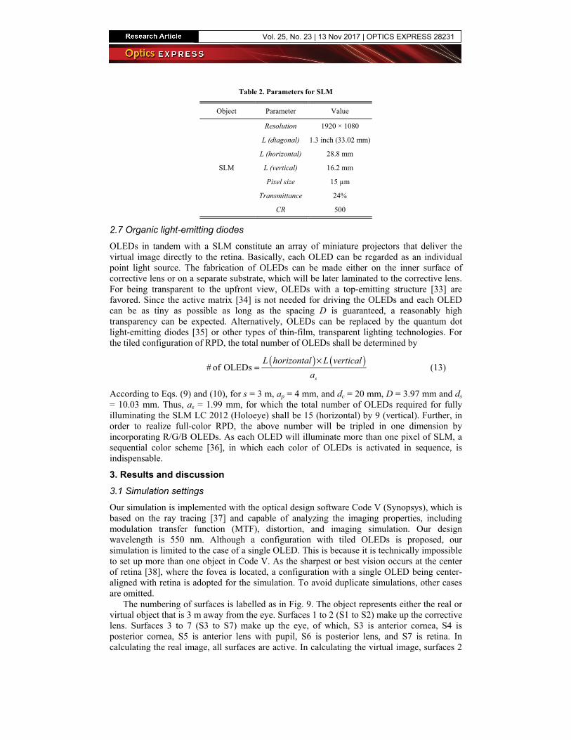
Table 2. Parameters for SLM
Object Parameter Value
SLM
Resolution 1920 × 1080
L (diagonal) 1.3 inch (33.02 mm)
L (horizontal) 28.8 mm
L (vertical) 16.2 mm
Pixel size 15 µm
Transmittance 24%
CR 500
2.7 Organic light-emitting diodes
OLEDs in tandem with a SLM constitute an array of miniature projectors that deliver the virtual image directly to the retina. Basically, each OLED can be regarded as an individual point light source. The fabrication of OLEDs can be made either on the inner surface of corrective lens or on a separate substrate, which will be later laminated to the corrective lens. For being transparent to the upfront view, OLEDs with a top-emitting structure [33] are favored. Since the active matrix [34] is not needed for driving the OLEDs and each OLED can be as tiny as possible as long as the spacing D is guaranteed, a reasonably high transparency can be expected. Alternatively, OLEDs can be replaced by the quantum dot light-emitting diodes [35] or other types of thin-film, transparent lighting technologies. For the tiled configuration of RPD, the total number of OLEDs shall be determined by
( ) ( )# of OLEDs
s
L horizontal L vertical
a
×= (13)
According to Eqs. (9) and (10), for s = 3 m, ap = 4 mm, and dc = 20 mm, D = 3.97 mm and ds = 10.03 mm. Thus, as = 1.99 mm, for which the total number of OLEDs required for fully illuminating the SLM LC 2012 (Holoeye) shall be 15 (horizontal) by 9 (vertical). Further, in order to realize full-color RPD, the above number will be tripled in one dimension by incorporating R/G/B OLEDs. As each OLED will illuminate more than one pixel of SLM, a sequential color scheme [36], in which each color of OLEDs is activated in sequence, is indispensable.
3. Results and discussion
3.1 Simulation settings
Our simulation is implemented with the optical design software Code V (Synopsys), which is based on the ray tracing [37] and capable of analyzing the imaging properties, including modulation transfer function (MTF), distortion, and imaging simulation. Our design wavelength is 550 nm. Although a configuration with tiled OLEDs is proposed, our simulation is limited to the case of a single OLED. This is because it is technically impossible to set up more than one object in Code V. As the sharpest or best vision occurs at the center of retina [38], where the fovea is located, a configuration with a single OLED being center-aligned with retina is adopted for the simulation. To avoid duplicate simulations, other cases are omitted.
The numbering of surfaces is labelled as in Fig. 9. The object represents either the real or virtual object that is 3 m away from the eye. Surfaces 1 to 2 (S1 to S2) make up the corrective lens. Surfaces 3 to 7 (S3 to S7) make up the eye, of which, S3 is anterior cornea, S4 is posterior cornea, S5 is anterior lens with pupil, S6 is posterior lens, and S7 is retina. In calculating the real image, all surfaces are active. In calculating the virtual image, surfaces 2
Vol. 25, No. 23 | 13 Nov 2017 | OPTICS EXPRESS 28231
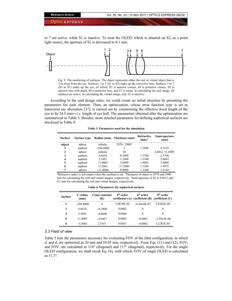
to 7 are active, while S1 is inactive. To treat the OLED, which is situated on S2, as a point light source, the aperture of S2 is decreased to 0.1 mm.
1 3 4 5 6 7Object
2
Fig. 9. The numbering of surfaces. The object represents either the real or virtual object that is 2 m away from the eye. Surfaces 1 to 2 (S1 to S2) make up the corrective lens. Surfaces 3 to 7 (S3 to S7) make up the eye, of which, S3 is anterior cornea, S4 is posterior cornea, S5 is anterior lens with pupil, S6 is posterior lens, and S7 is retina. In calculating the real image, all surfaces are active. In calculating the virtual image, only S1 is inactive.
According to the said design rules, we could create an initial structure by presetting the parameters for each element. Then, an optimization, whose error function type is set as transverse ray aberration [37], is carried out by constraining the effective focal length of the eye to be 24.5 mm―i.e. length of eye ball. The parameters obtained after the optimization are summarized in Table 3. Besides, more detailed parameters for defining aspherical surfaces are disclosed in Table 4.
Table 3. Parameters used for the simulation
Surface Surface type Radius (mm) Thickness (mm)Refractive
indexa Semi-aperture
(mm)
object sphere infinity 2978 / 2980b
1 asphere −294.8000 2 1.5896 4.51452 sphere infinity 20 4.4012 / 0.1000c 3 asphere 6.6624 0.5000 1.3760 2.57904 asphere 3.5491 3.1600 1.3360 2.40655 asphere 11.4085 3.6000 1.4085 2.00006 asphere −5.5801 17.2000 1.3360 1.9972 7 sphere −11.0000 0.0000 1.3360 1.6144
aRefractive index is left empty when the medium is air. bThickness of object is 2978 and 2980 mm for calculating the real and virtual images, respectively. cSemi-aperture of S2 is 4.4012 and 0.1 mm for calculating the real and virtual images, respectively.
Table 4. Parameters for aspherical surfaces
Surface Y radius
(mm) Conic constant
(K) 4th order
coefficient (A)6th order
coefficient (B)8th order
coefficient (C)
1 −294.8000 0 1.0878E-05 −6.5664E-07 9.8302E-09
3 6.6624 −0.1800 0.0002 0 0
4 3.5491 −0.6000 0.0040 0 0
5 11.4085 −0.9427 0.0005 −0.0002 −2.9563E-06
6 −5.5801 2.5161 0.0051 −0.0002 3.2283E-05
3.3 Field of view
Table 5 lists the parameters necessary for evaluating FOV of the tiled configuration, in which dc and ds are optimized as 20 mm and 10.03 mm, respectively. From Eqs. (11) and (12), FOVr and FOVv are calculated as 114° (diagonal) and 117° (diagonal), respectively. For the single OLED configuration, we shall recall Eq. (8), with which, FOV of single OLED is calculated as 11.3°.
Vol. 25, No. 23 | 13 Nov 2017 | OPTICS EXPRESS 28232
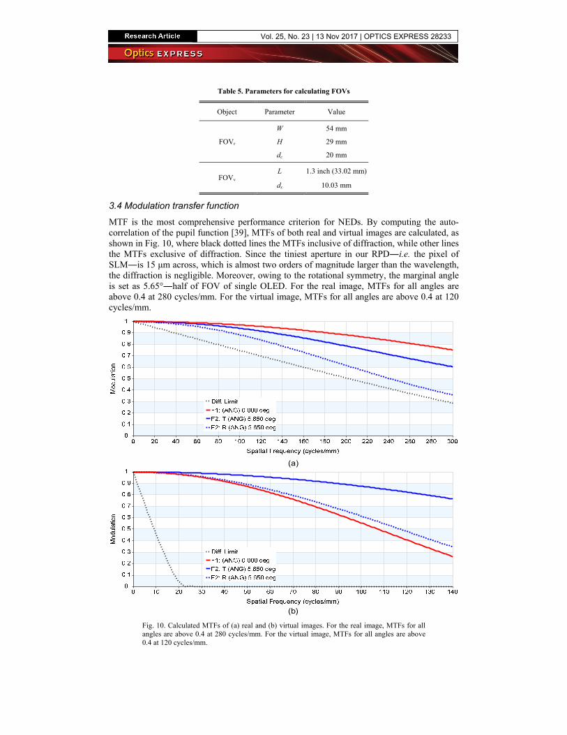
Table 5. Parameters for calculating FOVs
Object Parameter Value
FOVr
W 54 mm
H 29 mm
dc 20 mm
FOVv L 1.3 inch (33.02 mm)
ds 10.03 mm
3.4 Modulation transfer function
MTF is the most comprehensive performance criterion for NEDs. By computing the auto-correlation of the pupil function [39], MTFs of both real and virtual images are calculated, as shown in Fig. 10, where black dotted lines the MTFs inclusive of diffraction, while other lines the MTFs exclusive of diffraction. Since the tiniest aperture in our RPD―i.e. the pixel of SLM―is 15 μm across, which is almost two orders of magnitude larger than the wavelength, the diffraction is negligible. Moreover, owing to the rotational symmetry, the marginal angle is set as 5.65°―half of FOV of single OLED. For the real image, MTFs for all angles are above 0.4 at 280 cycles/mm. For the virtual image, MTFs for all angles are above 0.4 at 120 cycles/mm.
(a)
(b)
Fig. 10. Calculated MTFs of (a) real and (b) virtual images. For the real image, MTFs for all angles are above 0.4 at 280 cycles/mm. For the virtual image, MTFs for all angles are above 0.4 at 120 cycles/mm.
Vol. 25, No. 23 | 13 Nov 2017 | OPTICS EXPRESS 28233
3.5 Contrast ratio
Contrast ratio (CR) is defined as the ratio of maximum intensity to minimum intensity, and it can be derived as [37]
1
1
M MTFCR
M MTF
+ ⋅=− ⋅
(14)
where M denotes the modulation in object, i.e.
1
1o
o
CRM
CR
−=
+(15)
where CRo is the CR of object. For the real object, CRo can be significantly large so that M is considered as 1. For the virtual object, CRo is the CR of SLM. From Eqs. (14) and (15), for the spatial frequency of 33.33 cycles/mm―which corresponds to a pixel size of 15 μm―at the central angle, CRs of real and virtual images are calculated as 666 and 31, respectively.
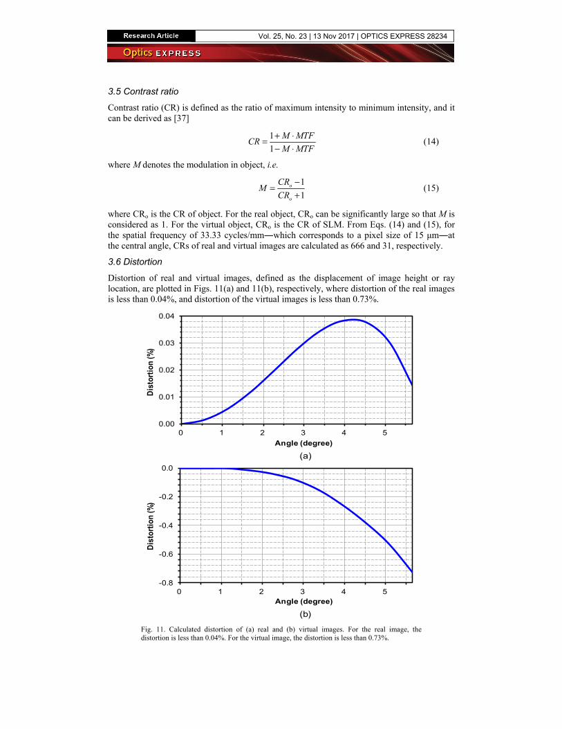
3.6 Distortion
Distortion of real and virtual images, defined as the displacement of image height or ray location, are plotted in Figs. 11(a) and 11(b), respectively, where distortion of the real images is less than 0.04%, and distortion of the virtual images is less than 0.73%.
-0.8
-0.6
-0.4
-0.2
0.0
0 1 2 3 4 5
Dis
tort
ion
(%)
Angle (degree)
0.00
0.01
0.02
0.03
0.04
0 1 2 3 4 5
Dis
tort
ion
(%)
Angle (degree)
(a)
(b)
Fig. 11. Calculated distortion of (a) real and (b) virtual images. For the real image, the distortion is less than 0.04%. For the virtual image, the distortion is less than 0.73%.
Vol. 25, No. 23 | 13 Nov 2017 | OPTICS EXPRESS 28234
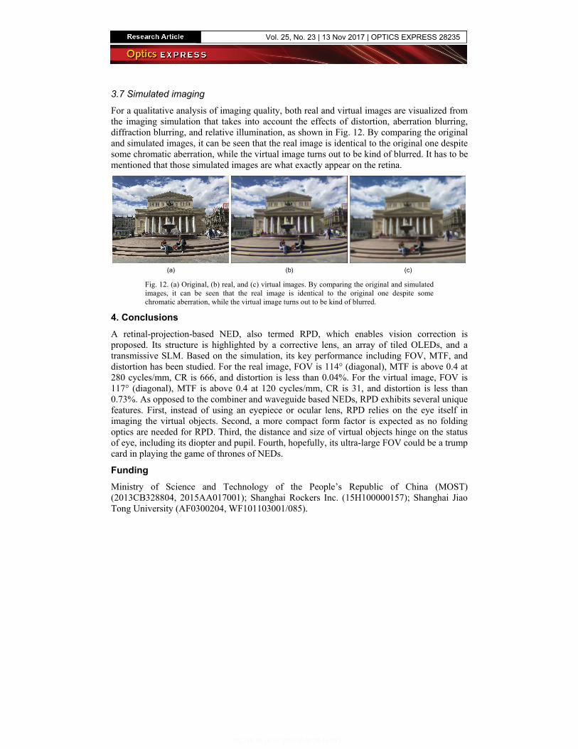
3.7 Simulated imaging
For a qualitative analysis of imaging quality, both real and virtual images are visualized from the imaging simulation that takes into account the effects of distortion, aberration blurring, diffraction blurring, and relative illumination, as shown in Fig. 12. By comparing the original and simulated images, it can be seen that the real image is identical to the original one despite some chromatic aberration, while the virtual image turns out to be kind of blurred. It has to be mentioned that those simulated images are what exactly appear on the retina.
(a) (b) (c)
Fig. 12. (a) Original, (b) real, and (c) virtual images. By comparing the original and simulated images, it can be seen that the real image is identical to the original one despite some chromatic aberration, while the virtual image turns out to be kind of blurred.
4. Conclusions
A retinal-projection-based NED, also termed RPD, which enables vision correction is proposed. Its structure is highlighted by a corrective lens, an array of tiled OLEDs, and a transmissive SLM. Based on the simulation, its key performance including FOV, MTF, and distortion has been studied. For the real image, FOV is 114° (diagonal), MTF is above 0.4 at 280 cycles/mm, CR is 666, and distortion is less than 0.04%. For the virtual image, FOV is 117° (diagonal), MTF is above 0.4 at 120 cycles/mm, CR is 31, and distortion is less than 0.73%. As opposed to the combiner and waveguide based NEDs, RPD exhibits several unique features. First, instead of using an eyepiece or ocular lens, RPD relies on the eye itself in imaging the virtual objects. Second, a more compact form factor is expected as no folding optics are needed for RPD. Third, the distance and size of virtual objects hinge on the status of eye, including its diopter and pupil. Fourth, hopefully, its ultra-large FOV could be a trump card in playing the game of thrones of NEDs.
Funding
Ministry of Science and Technology of the People’s Republic of China (MOST) (2013CB328804, 2015AA017001); Shanghai Rockers Inc. (15H100000157); Shanghai Jiao Tong University (AF0300204, WF101103001/085).
Vol. 25, No. 23 | 13 Nov 2017 | OPTICS EXPRESS 28235