Embed Size (px)
Citation preview
Design of subsea rigid pipelines – The free span probl em
4th COPEDI Forum / 2013
Comitê Offshore para Pesquisa, Desenvolvimento e Inovaç ão
11/11/2013
Design of subsea rigid pipelines Design of subsea rigid pipelines The free span problemThe free span problem
Design of subsea rigid pipelines – The free span probl em
CONTENT :
• Overview of pipelines design process;
• Free span definitions;
• Free span project;
• Free span mitigation;
• Structural integrity monitoring;
• History of failure;
• Design methodology - DNV RP F105;
• Sensitivity studies;
• Conclusions.
Design of subsea rigid pipelines – The free span probl em
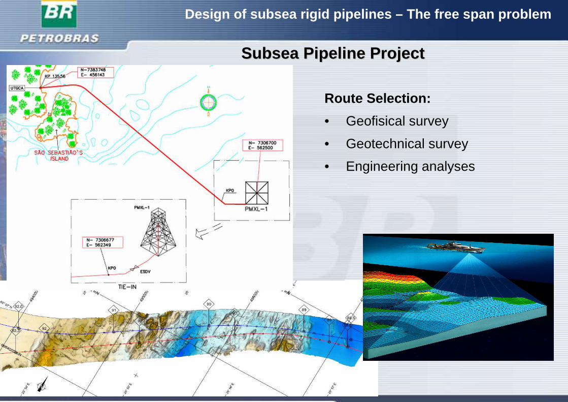
Route Selection:
• Geofisical survey
• Geotechnical survey
• Engineering analyses
SubseaSubsea PipelinePipeline Project Project
Design of subsea rigid pipelines – The free span probl em
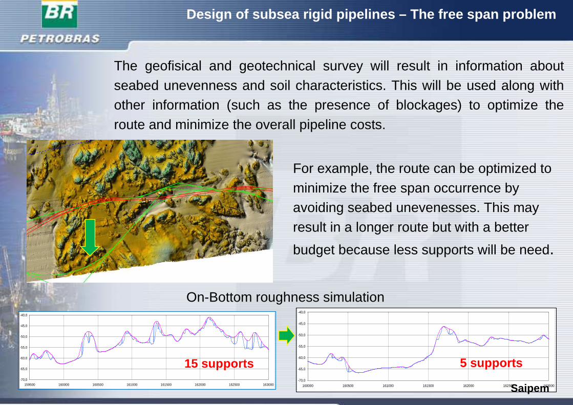
For example, the route can be optimized to minimize the free span occurrence byavoiding seabed unevenesses. This may result in a longer route but with a better
budget because less supports will be need.
On-Bottom roughness simulation
-70,0
-65,0
-60,0
-55,0
-50,0
-45,0
-40,0
159500 160000 160500 161000 161500 162000 162500 163000
15 supports-70,0
-65,0
-60,0
-55,0
-50,0
-45,0
-40,0
160000 160500 161000 161500 162000 162500 163000
5 supports
Saipem
The geofisical and geotechnical survey will result in information about seabed unevenness and soil characteristics. This will be used along with other information (such as the presence of blockages) to optimize the route and minimize the overall pipeline costs.
.
Design of subsea rigid pipelines – The free span probl em
SubseaSubsea PipelinePipeline Project Project
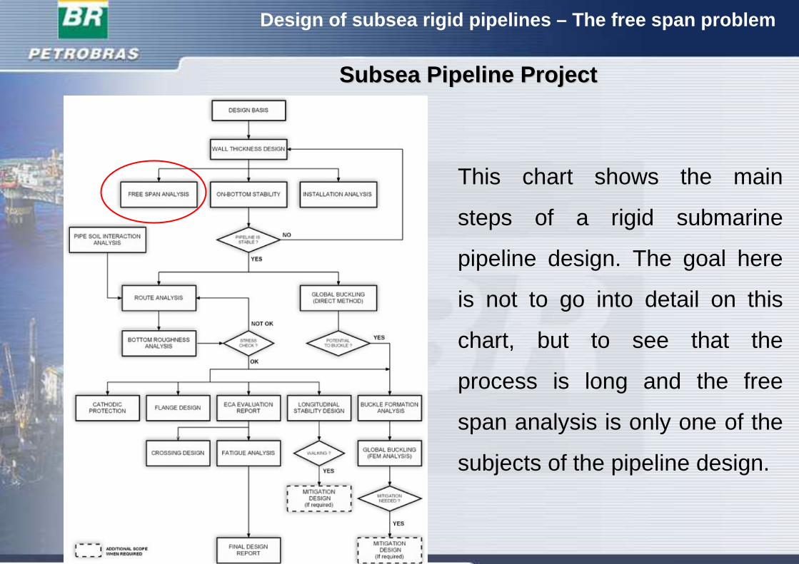
This chart shows the main
steps of a rigid submarine
pipeline design. The goal here
is not to go into detail on this
chart, but to see that the
process is long and the free
span analysis is only one of the
subjects of the pipeline design.
Design of subsea rigid pipelines – The free span probl em
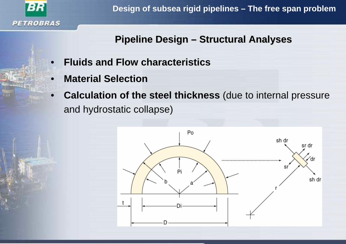
• Fluids and Flow characteristics
• Material Selection
• Calculation of the steel thickness (due to internal pressureand hydrostatic collapse)
PipelinePipeline Design Design –– StructuralStructural AnalysesAnalyses
Design of subsea rigid pipelines – The free span probl em
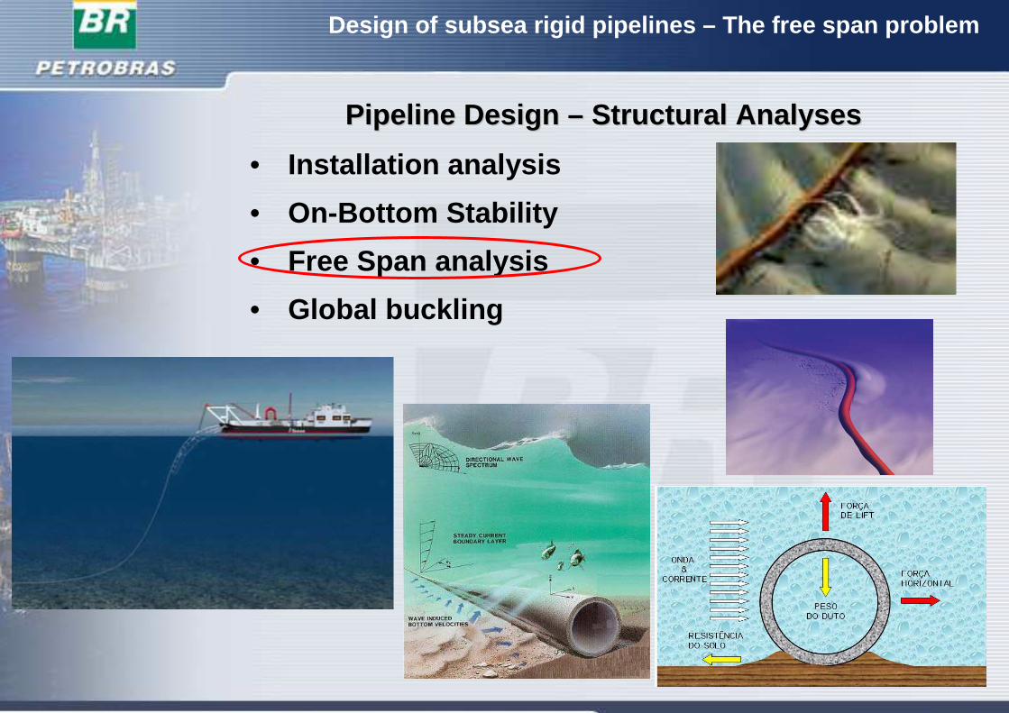
• Installation analysis
• On-Bottom Stability
• Free Span analysis
• Global buckling
PipelinePipeline Design Design –– StructuralStructural AnalysesAnalyses
Design of subsea rigid pipelines – The free span probl em
FreeFree SpanSpan AnalysisAnalysis
L
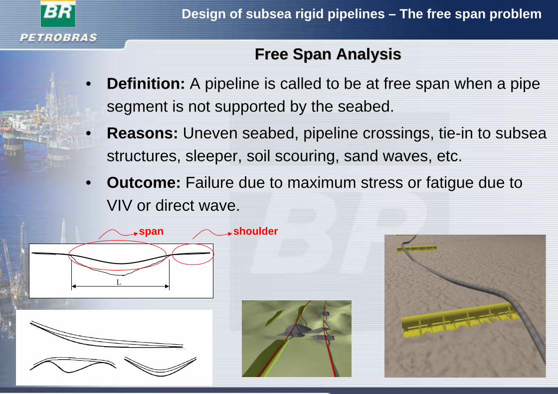
• Definition: A pipeline is called to be at free span when a pipe segment is not supported by the seabed.
• Reasons: Uneven seabed, pipeline crossings, tie-in to subseastructures, sleeper, soil scouring, sand waves, etc.
• Outcome: Failure due to maximum stress or fatigue due to VIV or direct wave.
span shoulder
Design of subsea rigid pipelines – The free span probl em
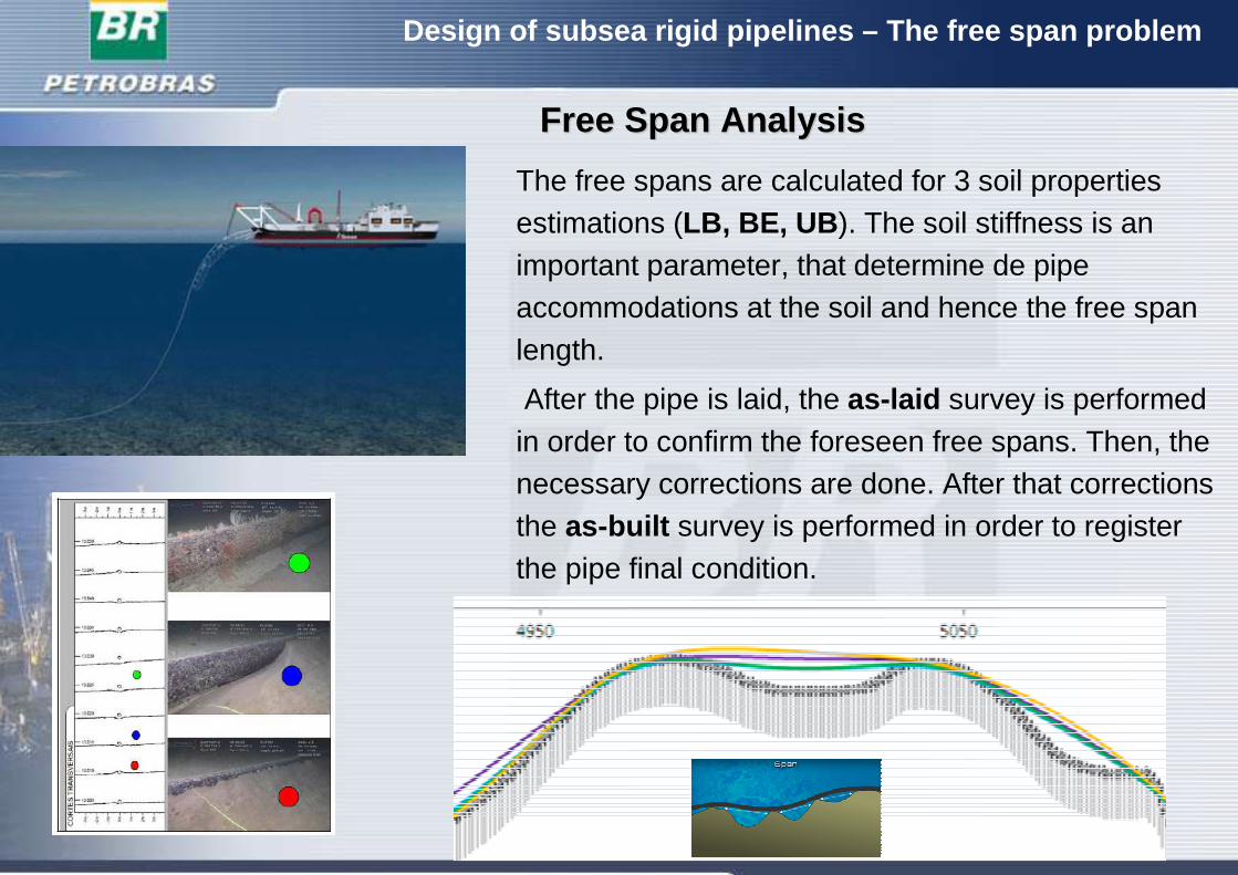
The free spans are calculated for 3 soil properties estimations (LB, BE, UB ). The soil stiffness is an important parameter, that determine de pipe accommodations at the soil and hence the free span length.
After the pipe is laid, the as-laid survey is performed in order to confirm the foreseen free spans. Then, the necessary corrections are done. After that corrections the as-built survey is performed in order to register the pipe final condition.
FreeFree SpanSpan AnalysisAnalysis
Design of subsea rigid pipelines – The free span probl em
FreeFree SpanSpan AnalysisAnalysis
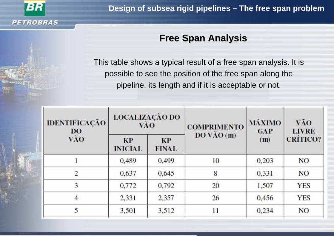
This table shows a typical result of a free span analysis. It ispossible to see the position of the free span along the
pipeline, its length and if it is acceptable or not.
Design of subsea rigid pipelines – The free span probl em
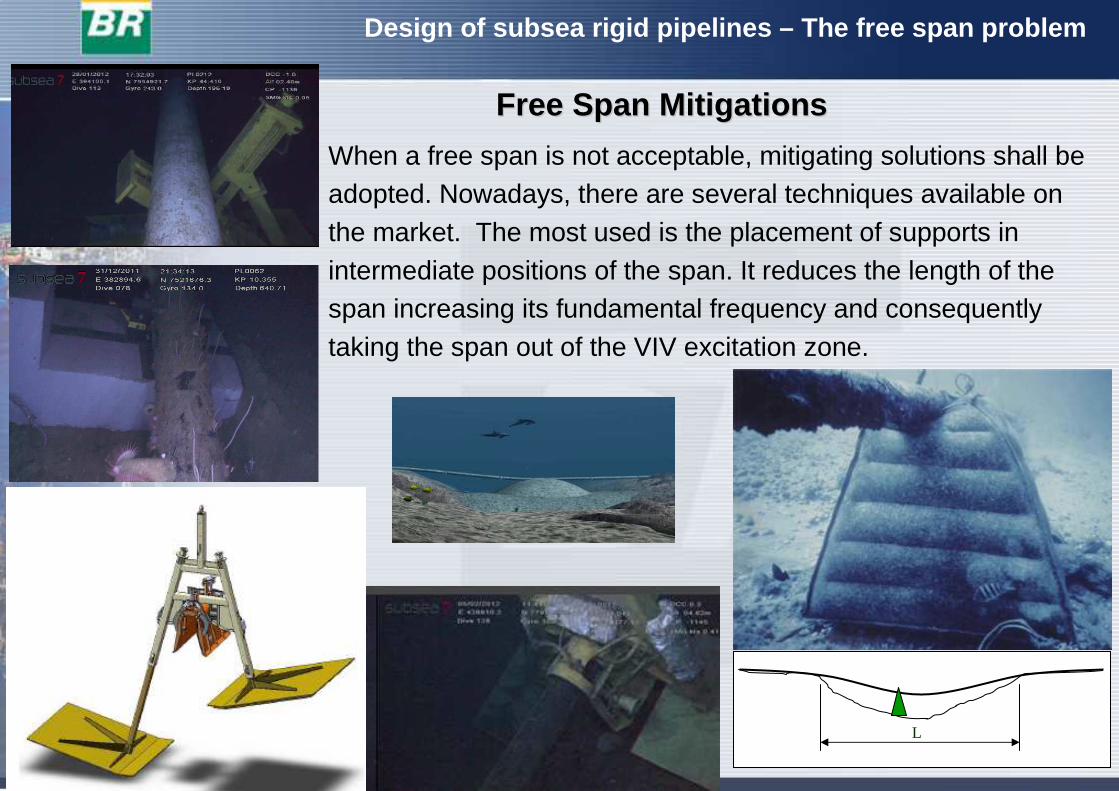
When a free span is not acceptable, mitigating solutions shall be adopted. Nowadays, there are several techniques available on the market. The most used is the placement of supports in intermediate positions of the span. It reduces the length of thespan increasing its fundamental frequency and consequently taking the span out of the VIV excitation zone.
FreeFree SpanSpan MitigationsMitigations
L
Design of subsea rigid pipelines – The free span probl em
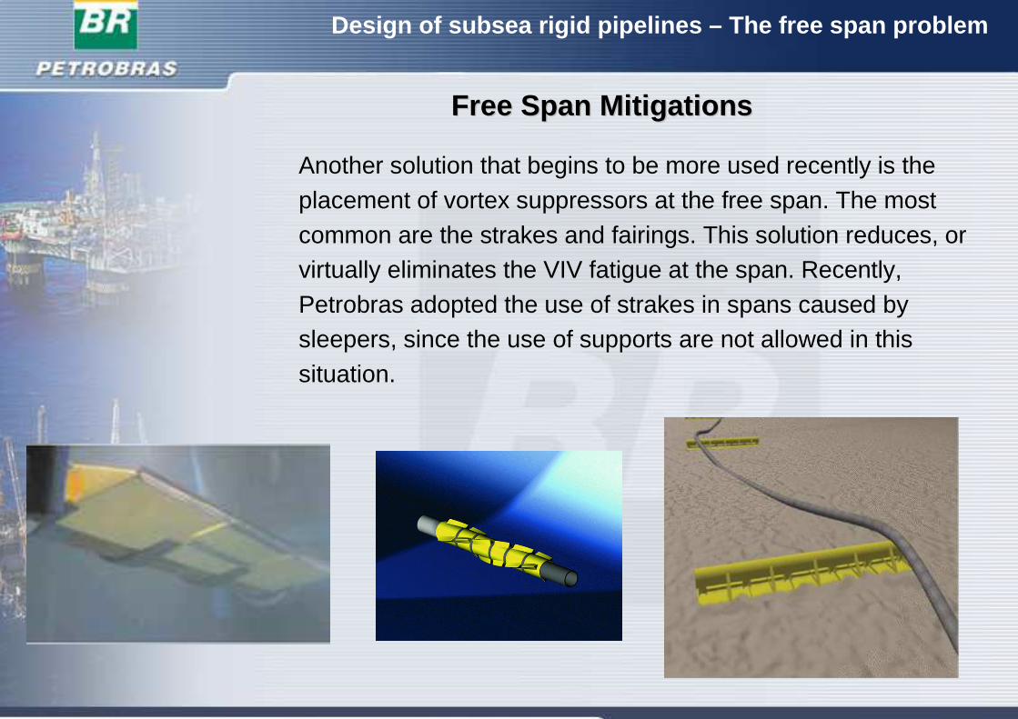
FreeFree SpanSpan MitigationsMitigations
Another solution that begins to be more used recently is the placement of vortex suppressors at the free span. The most common are the strakes and fairings. This solution reduces, or virtually eliminates the VIV fatigue at the span. Recently, Petrobras adopted the use of strakes in spans caused by sleepers, since the use of supports are not allowed in this situation.
Design of subsea rigid pipelines – The free span probl em
FreeFree SpanSpan MitigationsMitigations
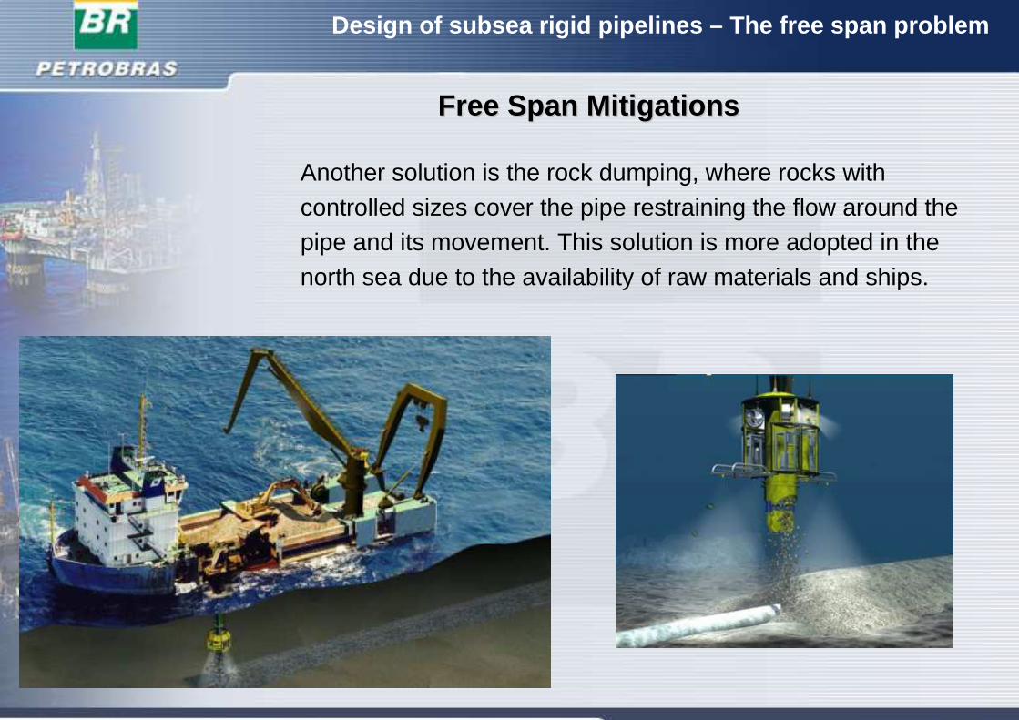
Another solution is the rock dumping, where rocks with controlled sizes cover the pipe restraining the flow around the pipe and its movement. This solution is more adopted in the north sea due to the availability of raw materials and ships.
Design of subsea rigid pipelines – The free span probl em
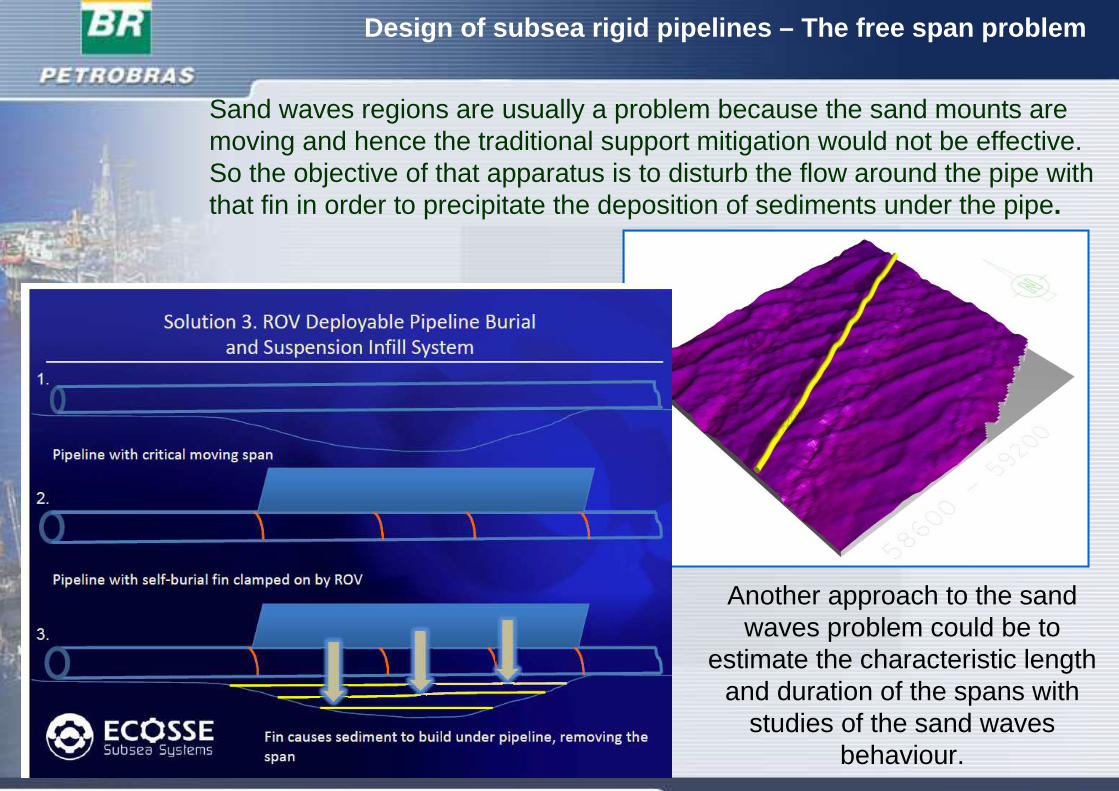
Sand waves regions are usually a problem because the sand mounts are moving and hence the traditional support mitigation would not be effective.So the objective of that apparatus is to disturb the flow around the pipe with that fin in order to precipitate the deposition of sediments under the pipe.
Another approach to the sandwaves problem could be to
estimate the characteristic lengthand duration of the spans with
studies of the sand wavesbehaviour.
Design of subsea rigid pipelines – The free span probl em
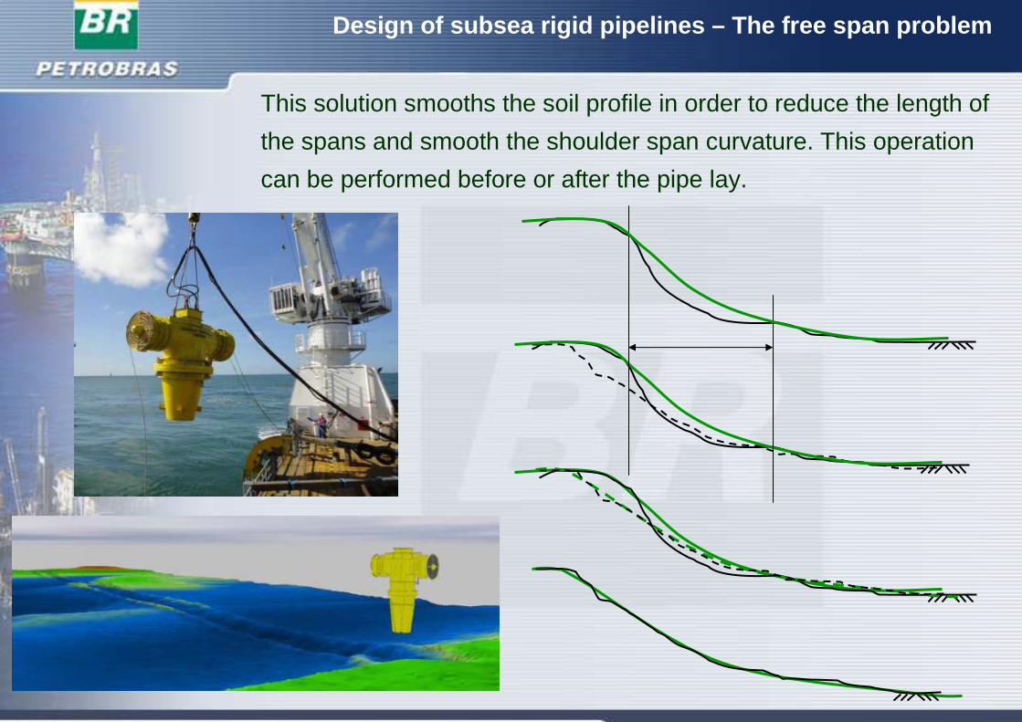
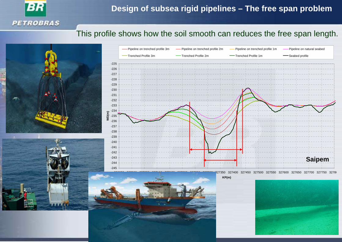
This solution smooths the soil profile in order to reduce the length of
the spans and smooth the shoulder span curvature. This operation
can be performed before or after the pipe lay.
Design of subsea rigid pipelines – The free span probl em
This profile shows how the soil smooth can reduces the free span length.
Saipem-245
-244
-243
-242
-241
-240
-239
-238
-237
-236
-235
-234
-233
-232
-231
-230
-229
-228
-227
-226
-225
326950 327000 327050 327100 327150 327200 327250 327300 327350 327400 327450 327500 327550 327600 327650 327700 327750 327800
KP(m)
WD
(m)
Pipeline on trenched profile 3m Pipeline on trenched profile 2m Pipeline on trenched profile 1m Pipeline on natural seabed
Trenched Profile 3m Trenched Profile 2m Trenched Profile 1m Seabed profile
Design of subsea rigid pipelines – The free span probl em
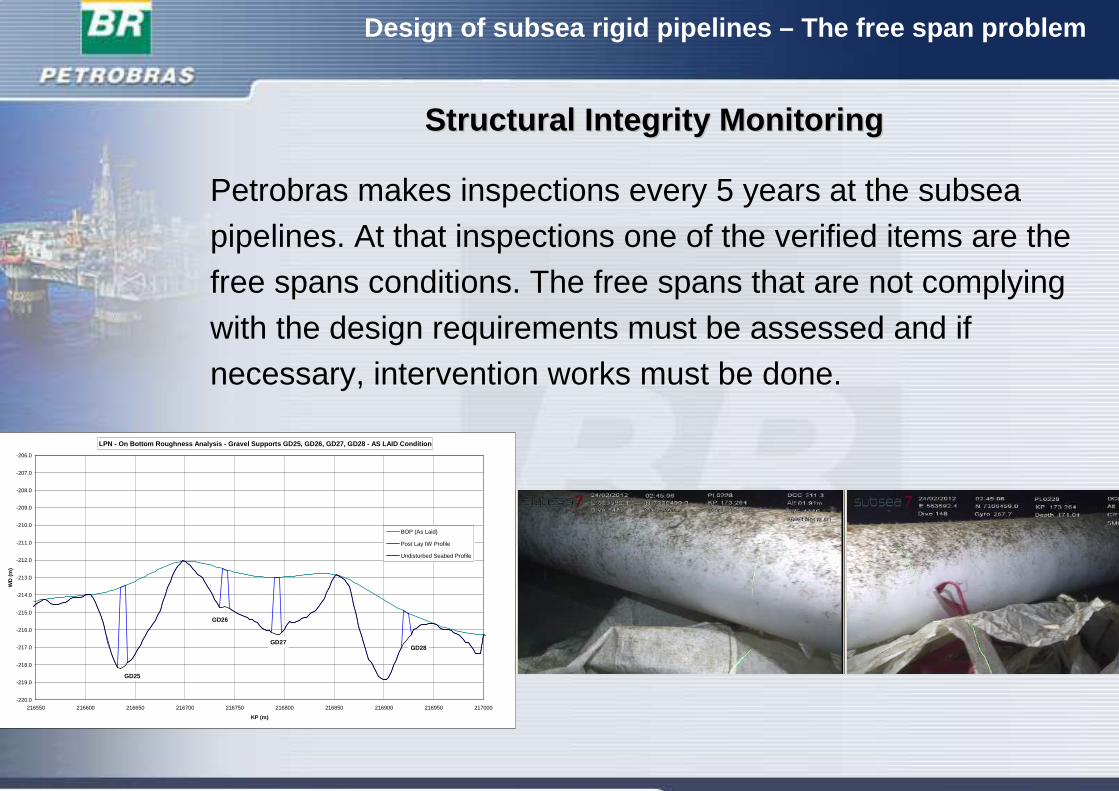
Petrobras makes inspections every 5 years at the subsea pipelines. At that inspections one of the verified items are thefree spans conditions. The free spans that are not complying with the design requirements must be assessed and if necessary, intervention works must be done.
StructuralStructural IntegrityIntegrity MonitoringMonitoring
LPN - On Bottom Roughness Analysis - Gravel Support s GD25, GD26, GD27, GD28 - AS LAID Condition
-220.0
-219.0
-218.0
-217.0
-216.0
-215.0
-214.0
-213.0
-212.0
-211.0
-210.0
-209.0
-208.0
-207.0
-206.0
216550 216600 216650 216700 216750 216800 216850 216900 216950 217000
KP (m)
WD
(m
)
BOP (As Laid)
Post Lay IW Profile
Undisturbed Seabed Profile
GD27
GD25
GD26
GD28
Design of subsea rigid pipelines – The free span probl em
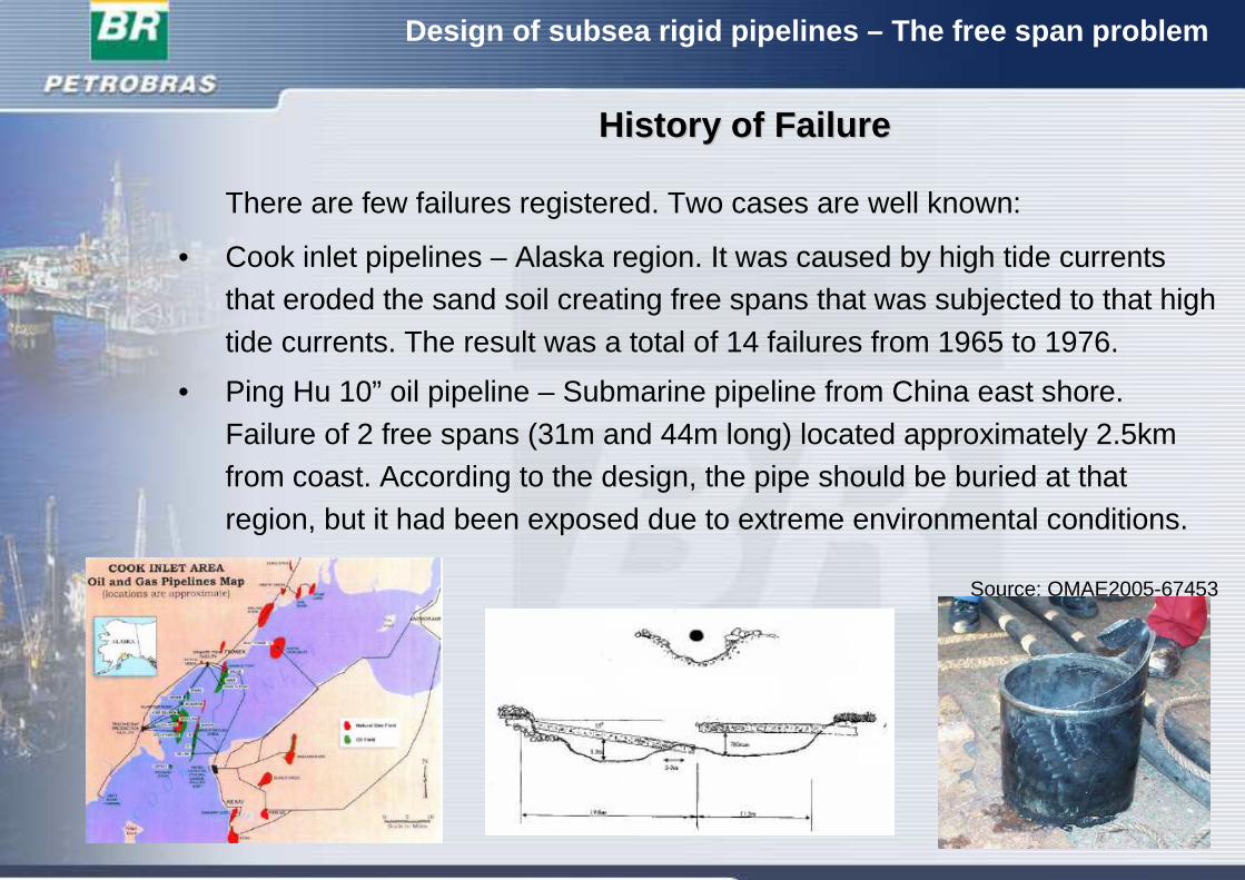
There are few failures registered. Two cases are well known:
• Cook inlet pipelines – Alaska region. It was caused by high tide currents that eroded the sand soil creating free spans that was subjected to that high tide currents. The result was a total of 14 failures from 1965 to 1976.
• Ping Hu 10” oil pipeline – Submarine pipeline from China east shore. Failure of 2 free spans (31m and 44m long) located approximately 2.5km from coast. According to the design, the pipe should be buried at thatregion, but it had been exposed due to extreme environmental conditions.
Source: OMAE2005-67453
HistoryHistory ofof FailureFailure
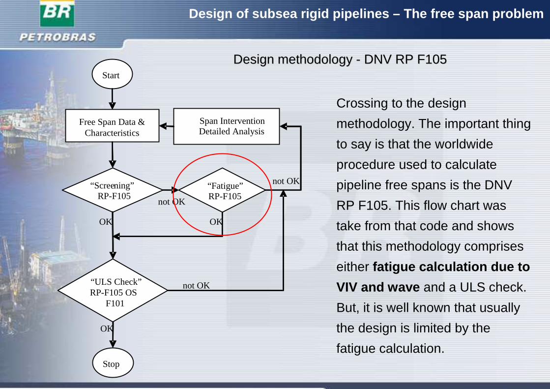
Design Design methodologymethodology -- DNV RP F105DNV RP F105
Crossing to the design
methodology. The important thing
to say is that the worldwide
procedure used to calculate
pipeline free spans is the DNV
RP F105. This flow chart was
take from that code and shows
that this methodology comprises
either fatigue calculation due to
VIV and wave and a ULS check.
But, it is well known that usually
the design is limited by the
fatigue calculation.
Design of subsea rigid pipelines – The free span probl em
Free Span Data & Characteristics
Start
Span InterventionDetailed Analysis
“Screening” “Fatigue”RP-F105
“ULS Check”RP-F105 OS
F101
Stop
not OK
OK OK
OK
not OK
not OK
RP-F105
Design of subsea rigid pipelines – The free span probl em
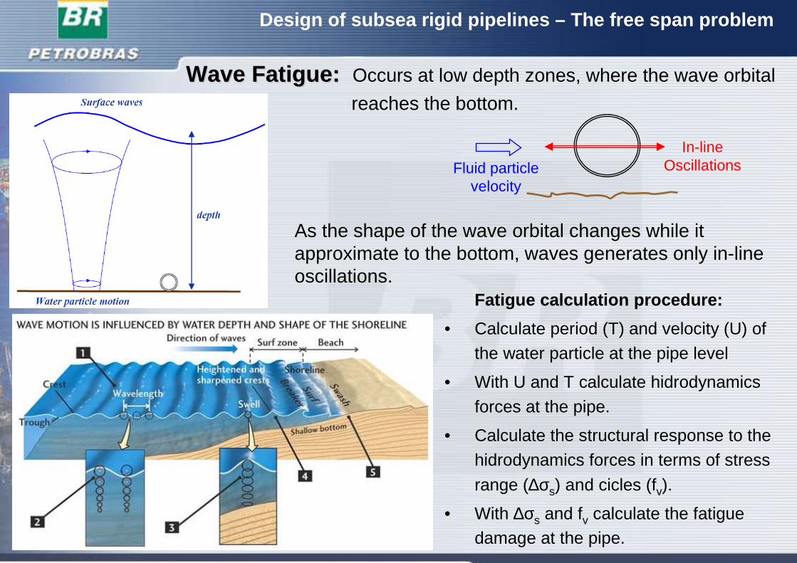
WaveWave Fatigue: Fatigue: Occurs at low depth zones, where the wave orbital
reaches the bottom.
Fatigue calculation procedure:
• Calculate period (T) and velocity (U) of
the water particle at the pipe level
• With U and T calculate hidrodynamics
forces at the pipe.
• Calculate the structural response to thehidrodynamics forces in terms of stress
range (∆σs) and cicles (fv).
• With ∆σs and fv calculate the fatigue damage at the pipe.
As the shape of the wave orbital changes while it approximate to the bottom, waves generates only in-line oscillations.
Fluid particlevelocity
In-lineOscillations
Design of subsea rigid pipelines – The free span probl em
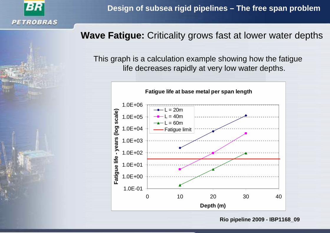
WaveWave Fatigue: Fatigue: Criticality grows fast at lower water depths
Fatigue life at base metal per span length
1.0E-01
1.0E+00
1.0E+01
1.0E+02
1.0E+03
1.0E+04
1.0E+05
1.0E+06
0 10 20 30 40
Depth (m)
Fat
igue
life
- ye
ars
(log
scal
e) L = 20m
L = 40mL = 60mFatigue limit
This graph is a calculation example showing how the fatigue life decreases rapidly at very low water depths.
Rio pipeline 2009 - IBP1168_09
Design of subsea rigid pipelines – The free span probl em
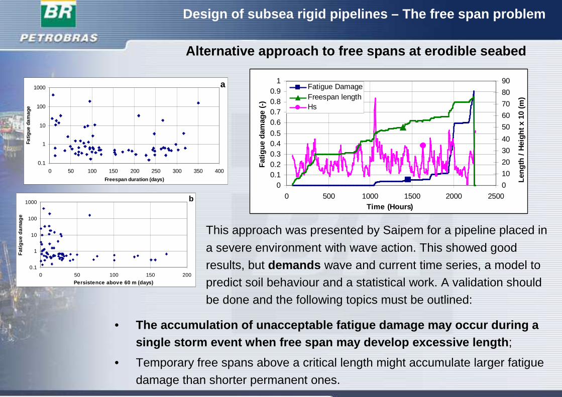
Alternative approach to free spans at erodible seabed
00.10.20.30.40.5
0.60.70.80.9
1
0 500 1000 1500 2000 2500Time (Hours)
Fat
igue
dam
age
(-)
0
10
20
30
40
50
60
70
80
90
Leng
th /
Hei
ght x
10
(m)
Fatigue DamageFreespan lengthHs
0.1
1
10
100
1000
0 50 100 150 200 250 300 350 400
Freespan duration (days)
Fatig
ue d
amag
e
a
0.1
1
10
100
1000
0 50 100 150 200
Persistence above 60 m (days)
Fat
igue
dam
age
b
This approach was presented by Saipem for a pipeline placed in
a severe environment with wave action. This showed good
results, but demands wave and current time series, a model to predict soil behaviour and a statistical work. A validation should
be done and the following topics must be outlined:
• The accumulation of unacceptable fatigue damage may occur during a single storm event when free span may develop excessive leng th ;
• Temporary free spans above a critical length might accumulate larger fatigue
damage than shorter permanent ones.
Design of subsea rigid pipelines – The free span probl em
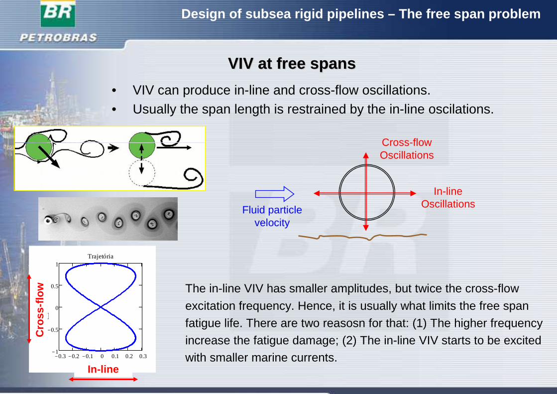
VIV VIV atat freefree spansspans
The in-line VIV has smaller amplitudes, but twice the cross-flow
excitation frequency. Hence, it is usually what limits the free span
fatigue life. There are two reasosn for that: (1) The higher frequency
increase the fatigue damage; (2) The in-line VIV starts to be excitedwith smaller marine currents.0.3− 0.2− 0.1− 0 0.1 0.2 0.3
1−
0.5−
0
0.5
1Trajetória
y 0 t,
( )
x 0 t,
( )In-line
Cro
ss-f
low
• VIV can produce in-line and cross-flow oscillations.• Usually the span length is restrained by the in-line oscilations.
Fluid particlevelocity
In-lineOscillations
Cross-flowOscillations
VIV Fatigue VIV Fatigue –– DNVDNV--RPRP--F105F105
nR fD
VV
⋅=
Design of subsea rigid pipelines – The free span probl em
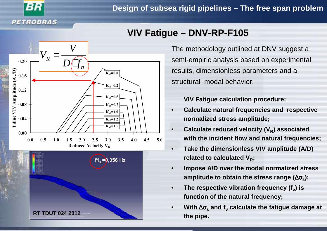
The methodology outlined at DNV suggest a
semi-empiric analysis based on experimental
results, dimensionless parameters and a
structural modal behavior.
VIV Fatigue calculation procedure:
• Calculate natural frequencies and respectivenormalized stress amplitude;
• Calculate reduced velocity (V R) associatedwith the incident flow and natural frequencies;
• Take the dimensionless VIV amplitude (A/D) related to calculated V R;
• Impose A/D over the modal normalized stress amplitude to obtain the stress range ( ∆σ∆σ∆σ∆σs);
• The respective vibration frequency (f v) is function of the natural frequency;
• With ∆σ∆σ∆σ∆σs and f v calculate the fatigue damage atthe pipe.RT TDUT 024 2012
Design of subsea rigid pipelines – The free span probl em
Mod 3 – Modelo bi-rotulado do NMRI
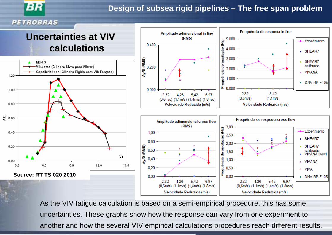
UncertaintiesUncertainties atat VIV VIV calculationscalculations
Source: RT TS 020 2010
As the VIV fatigue calculation is based on a semi-empirical procedure, this has some
uncertainties. These graphs show how the response can vary from one experiment to
another and how the several VIV empirical calculations procedures reach different results.

Design of subsea rigid pipelines – The free span probl em
Kristoffer Høyem Aronsen - Phd
Full line – DNV
Dashed line – Aronsen experiment for CL = 0 (rigidcylinder and forced oscillation)
These graph shows that the in-line VIV
phenomenon has a complicated behaviour
and the empirical VIV curve adopted at DNV
is an envelope curve.
Design of subsea rigid pipelines – The free span probl em
VIV VIV atat freefree spansspans –– SensitivitySensitivity to to thethe spanspan lengthlength
1.0E-02
1.0E-01
1.0E+00
1.0E+01
1.0E+02
1.0E+03
1.0E+04
1.0E+05
1.0E+06
1.0E+07
1.0E+08
1.0E+09
1.0E+10
0 20 40 60 80 100 120 140
Span Lenght (m)
Spa
n Li
fe (
year
s)
Span Life - In Line VIV
Span Life - Cross Flow VIV
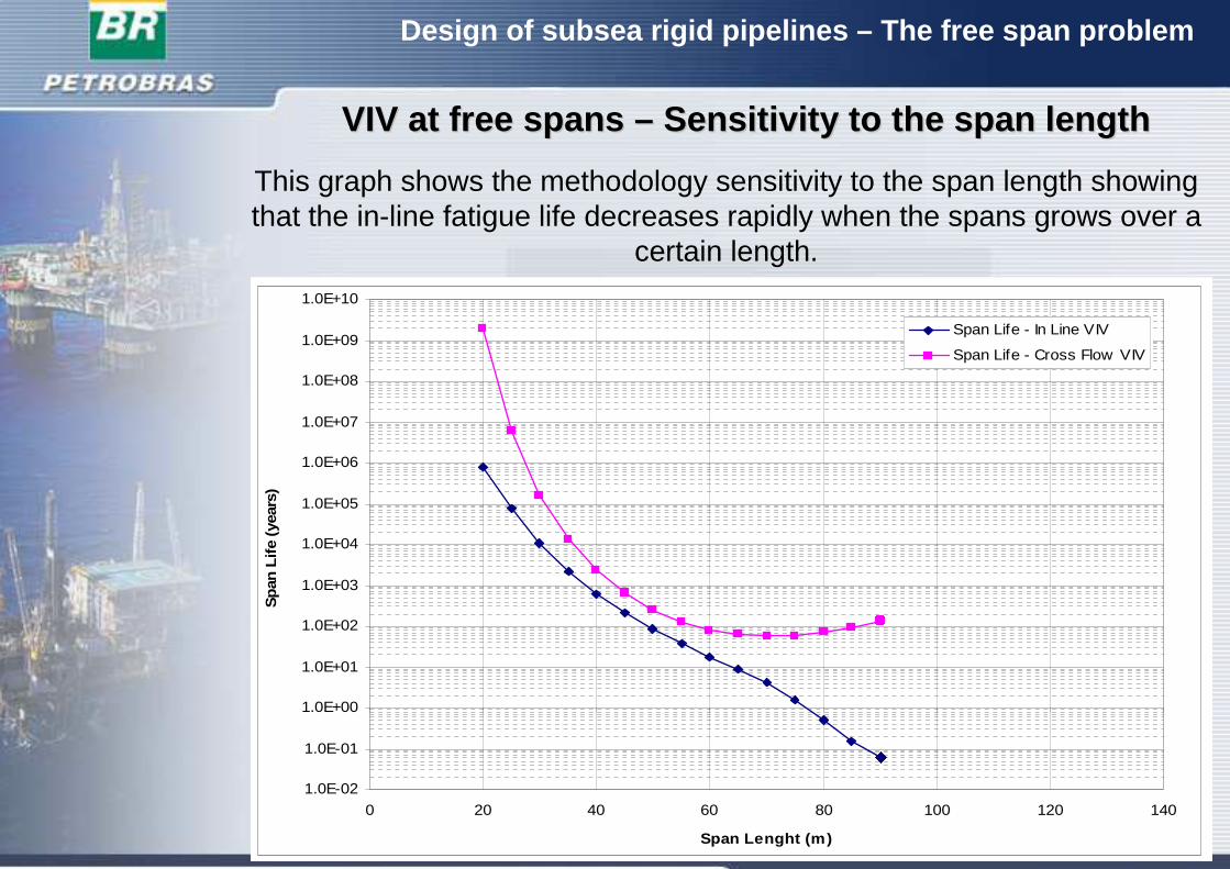
This graph shows the methodology sensitivity to the span length showing that the in-line fatigue life decreases rapidly when the spans grows over a
certain length.
Design of subsea rigid pipelines – The free span probl em
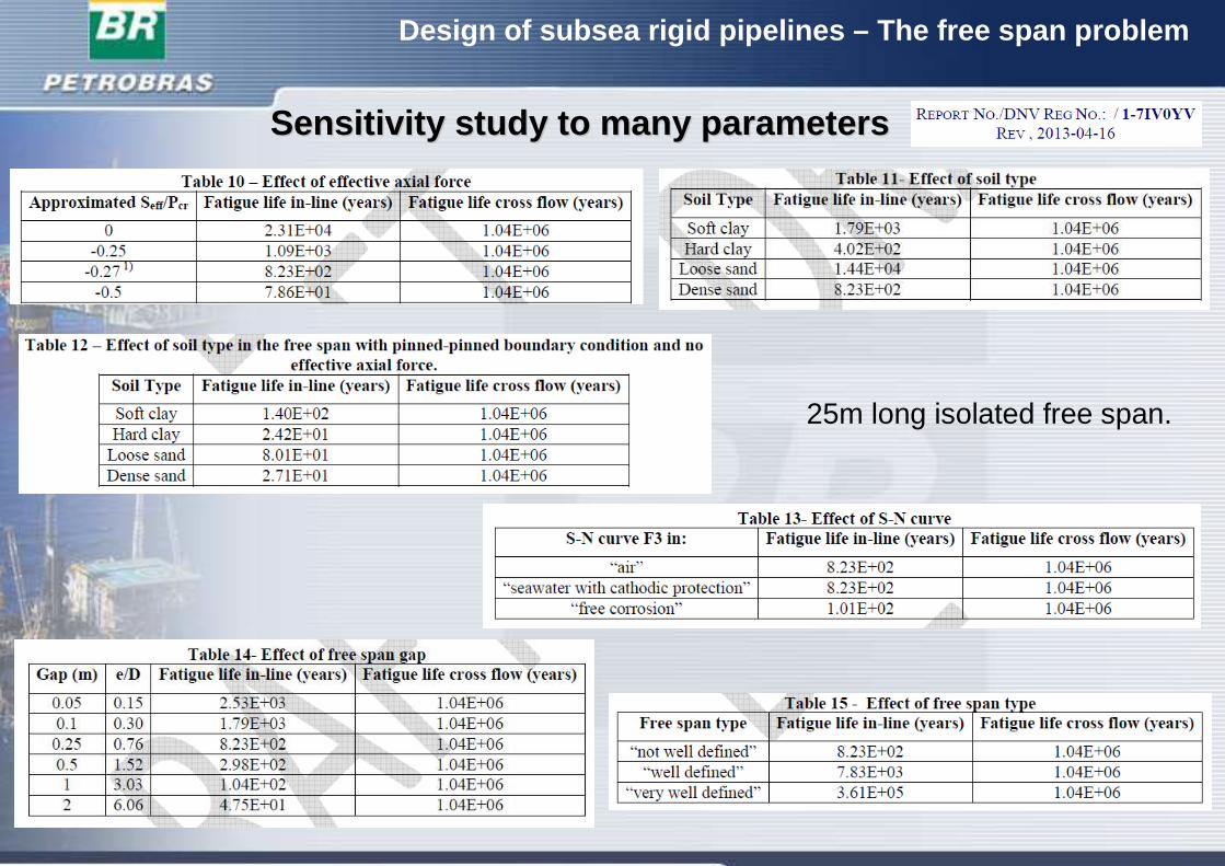
SensitivitySensitivity studystudy to to manymany parametersparameters
25m long isolated free span.
Design of subsea rigid pipelines – The free span probl em
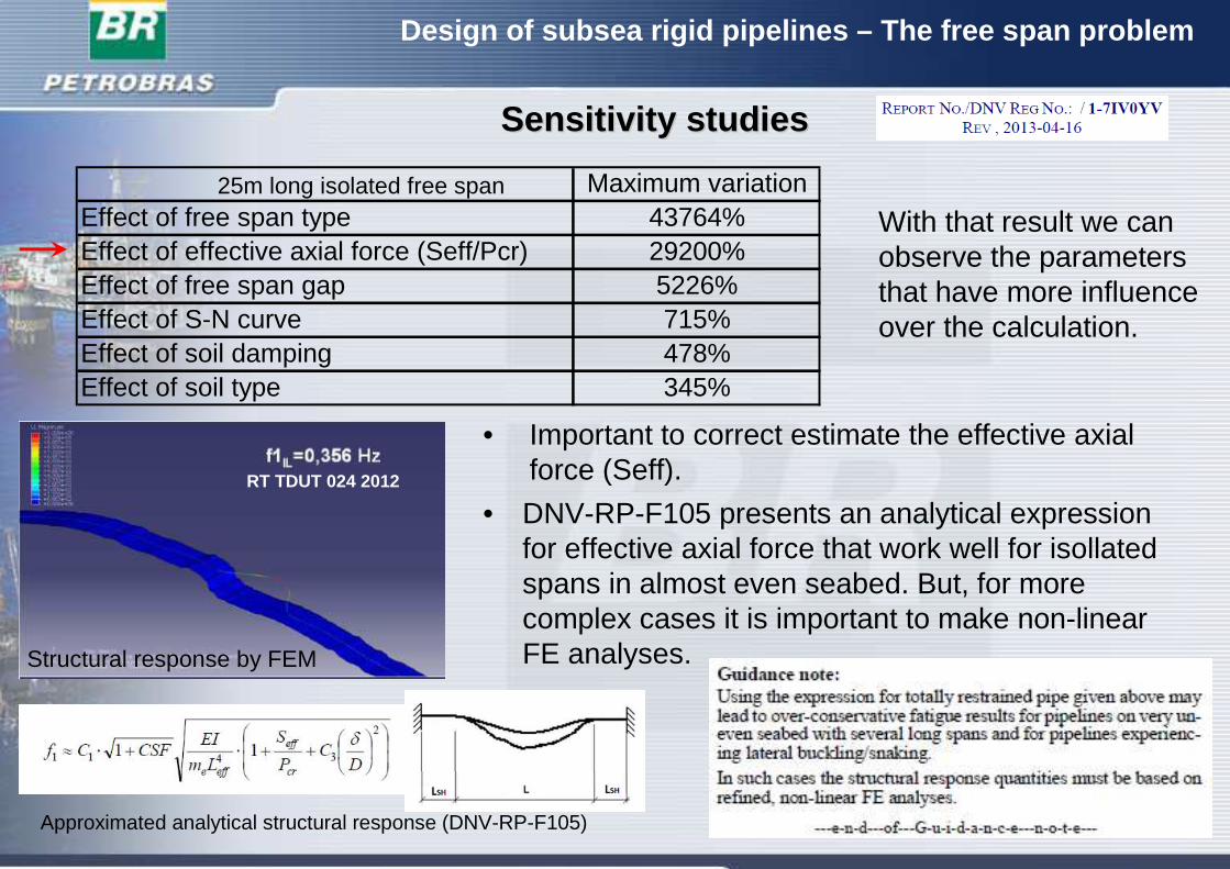
SensitivitySensitivity studiesstudies
Maximum variationEffect of free span type 43764%Effect of effective axial force (Seff/Pcr) 29200%Effect of free span gap 5226%Effect of S-N curve 715%Effect of soil damping 478%Effect of soil type 345%
• DNV-RP-F105 presents an analytical expressionfor effective axial force that work well for isollatedspans in almost even seabed. But, for more complex cases it is important to make non-linearFE analyses.
25m long isolated free span
Approximated analytical structural response (DNV-RP-F105)
RT TDUT 024 2012
Structural response by FEM
• Important to correct estimate the effective axial force (Seff).
With that result we can observe the parameters that have more influence over the calculation.
Design of subsea rigid pipelines – The free span probl em
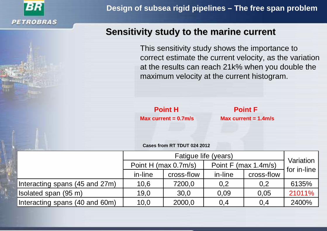
SensitivitySensitivity studystudy to to thethe marine marine currentcurrent
Point FMax current = 1.4m/s
Point HMax current = 0.7m/s
This sensitivity study shows the importance to correct estimate the current velocity, as the variation at the results can reach 21k% when you double the maximum velocity at the current histogram.
Cases from RT TDUT 024 2012
in-line cross-flow in-line cross-flowInteracting spans (45 and 27m) 10,6 7200,0 0,2 0,2 6135%Isolated span (95 m) 19,0 30,0 0,09 0,05 21011%Interacting spans (40 and 60m) 10,0 2000,0 0,4 0,4 2400%
Variation for in-line
Point H (max 0.7m/s)Fatigue life (years)
Point F (max 1.4m/s)
Design of subsea rigid pipelines – The free span probl em
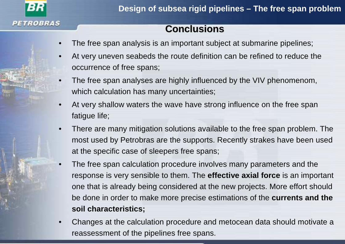
ConclusionsConclusions• The free span analysis is an important subject at submarine pipelines;
• At very uneven seabeds the route definition can be refined to reduce theoccurrence of free spans;
• The free span analyses are highly influenced by the VIV phenomenom, which calculation has many uncertainties;
• At very shallow waters the wave have strong influence on the free span fatigue life;
• There are many mitigation solutions available to the free span problem. Themost used by Petrobras are the supports. Recently strakes have been usedat the specific case of sleepers free spans;
• The free span calculation procedure involves many parameters and theresponse is very sensible to them. The effective axial force is an importantone that is already being considered at the new projects. More effort shouldbe done in order to make more precise estimations of the currents and thesoil characteristics;
• Changes at the calculation procedure and metocean data should motivate a reassessment of the pipelines free spans.
Design of subsea rigid pipelines – The free span probl em
Thank youThank you