Embed Size (px)
Citation preview

DESIGN OF ULTRA SMALL MICROSTRIP PATCH
ANTENNA FOR WIRELESS COMMUNICATION
APPLICATIONS
TANYA SHARMA (109EE0615)
OSHIN ATAL (109EE0530)
Department of Electrical Engineering
National Institute of Technology Rourkela
DESIGN OF ULTRA SMALL MICROSTRIP PATCH
ANTENNA FOR WIRELESS COMMUNICATION
APPLICATIONS
A Thesis submitted in partial fulfillment of the requirements for the degree of
Bachelor of Technology in “Electrical Engineering”
By
TANYA SHARMA (109EE0615)
OSHIN ATAL (109EE0530)
Under guidance of
Prof. Prasanna Kumar Sahu
Department of Electrical Engineering
National Institute of Technology
Rourkela-769008 (ODISHA)
May-2013

DEPARTMENT OF ELECTRICAL ENGINEERING
NATIONAL INSTITUTE OF TECHNOLOGY, ROURKELA
ODISHA, INDIA-769008
CERTIFICATE
This is to certify that the thesis entitled “Design of ultra small microstrip patch antenna
for wireless communication applications”, submitted by Tanya Sharma (109EE0615) and
Oshin Atal (109EE0530) in partial fulfilment of the requirements for the award of Bachelor
of Technology in Electrical Engineering during session 2012-2013 at National Institute of
Technology, Rourkela is a bonafide record of research work carried out by them under my
supervision and guidance.
The candidates have fulfilled all the prescribed requirements.
The Thesis which is based on candidates’ own work, have not submitted elsewhere for a
degree/diploma.
In my opinion, the thesis is of standard required for the award of a bachelor of technology
degree in Electrical Engineering.
Place: Rourkela
Dept. of Electrical Engineering Prof. Prasanna Kumar Sahu
National institute of Technology Associate Professor

ACKNOWLEDGEMENT
We have been highly indebted in the preparation of this thesis to our supervisor, Prof.
Prasanna Kumar Sahu whose patience and kindness, as well as his academic experience,
has been invaluable to us. We could not have asked for a better role model, inspirational,
supportive, and patient guide. His consistent support and unstinting guidance has always been
an immense source of motivation and encouragement.
Our sincere thanks to Ms. Sheeja K. L. for her constant guidance and encouragement and
providing us with all facilities and access to the resources vital to the completion of this
project.
Last but not the least, big thanks to NIT Rourkela for providing us such a platform
where learning has known no boundaries.
Oshin Atal and Tanya Sharma

ABSTRACT
This paper presents a narrow band microstrip patch antenna for wireless communication. A
microstrip patch antenna consists of a radiating patch on one side of a dielectric substrate and
has a ground plane on the other side. The main radiator is a rectangular patch made up of
copper. The advantages of this type of narrowband antennas are planar, smaller in size,
simple structure, low in cost and easy to be fabricated, etc. thus attractive for wireless
applications. Simulation of the antenna and subsequent adjustments of parameters gives apt
values for the antenna to work efficiently at low cost. At the later stage, comparison between
different antenna shapes has been provided and comparative study has been done in order to
list the advantages of each shape and decide which shape is best suited for the desired
wireless frequency of 1.7GHz. Also this work explores the performance enhancement of
multiple patch antennas. Comparative studies between the array and individual unit have
proved the betterment of results for wireless applications at 1.7GHz.

TABLE OF CONTENTS
i) ABSTRACT
ii) CONTENTS
iii) LIST OF FIGURES
iv) LIST OF TABLES
CONTENTS
CHAPTER 1. INRODUCTION 11
1.Introduction 12
1.1Merits of Microstrip patch antenna 13
1.2Demerits of Microstrip patch antenna 14
CHAPTER 2. MOTIVATION 15
2.Motivation 16
CHAPTER 3. THEORY OF MICROSTRIP PATCH ANTENNA 21
3.1 Types of Microstrip Patch Antennas 22
3.2 Feed techniques and modelling of Microstrip patch antenna 23
3.3 Radiation fields 27
3.4 Rectangular Microstrip patch antenna 30
CHAPTER 4.DESIGN OF RECTANULAR AND TRIANGULAR PATCH ATENNNA 33
4.1 Design calculation and simulation of Rectangular patch antenna at 1.7GHz 34
4.2 Results of Rectangular patch antenna at 1.7GHz 35
4.3 Design calculation and simulation of Triangular patch antenna at 1.7GHz 38
4.3 Results of Triangular patch antenna at 1.7GHz 39
4.4 Comparison of Rectangular and Triangular patch antenna 42

CHAPTER 5. DESIGN OF LINEAR RETANGULAR AND TRAINGULAR ARRAY 44
5.1 Rectangular array antenna 45
5.2 Triangular array antenna 49
5.3 Comparison between Rectangular and Traingular array patch antenna 53
CHAPTER 6. CONCLUSION 54
6. Conclusion 55
6.1 Future Work 55
References 56

LIST OF FIGURES
Fig. No Name of the Figure Page. No.
3.1 Coaxial probe feeding 24
3.2 Microstrip line feeding 25
3.3 Aperture coupled feeding 26
3.4 Proximity coupled feeding 27
4.1 Design of rectangular patch antenna 34
4.2 Return loss at 1.7GHz 35
4.3 3D plot of gain at 1.7GHz 36
4.4 VSWR at 1.7 GHz 36
4.5 E -plane at 1.7GHz 37
4.6 H-plane at 1.7GHz 37
4.7 Cartesian plot of directivity 38
Triangular Patch Antenna
4.8 Design of triangular patch antenna 38
4.9 Return loss at 1.7GHz 39
4.10 3D plot of gain at 1.7GHz 40
4.11 VSWR at 1.7GHz 40
4.12 E-plane at 1.7GHZ 41
4.13 H-plane at 1.7GHz 41
4.14 Cartesian plot of directivity 42
5.1 Design of rectangular array patch antenna 46
5.2 Return loss 46
5.3 3D plot of gain 47

5.3 H-plane at 1.5 GHz 48
5.4 E-plane at 1.5 GHz 48
5.5 Cartesian plot of directivity 49
5.6 VSWR at 1.5 GHz 50
Triangular Patch Array
5.7 Design of 2×1 array element 50
5.8 Return loss at 1.59 GHz 51
5.9 H-plane at 1.59 GHz 51
5.10 E-plane at 1.59 GHZ 52
5.11 3D plot of gain at 1.50 GHz 52
5.12 VSWR at 1.59 GHz 52

LIST OF TABLES
Table No Name of the Table Page No.
4.5 Comparison of Rectangular and Triangular patch 42
5.3 Comparison between rectangular and triangular array patch antenna 53

CHAPTER1.
INTRODUCTION

1. INTRODUCTION
In order to design patch antenna we used CST microwave studio. It is a special tool for the
simulation of high frequency components. It helps in the fast and accurate analysis of high
frequency such as filter, antennas, planar and multi-layer structures and signal integrity (SI)
and electromagnetic compatibility (EMC) effects.
Here, we used CST microwave studio to design antenna for wireless communication. We
have to create compact or even electrically small antennas that are compatible with the
modem technology. In order to design a patch antenna, we require:-
Antenna tuning
Voltage standing wave radio (VSWR) and return loss
Bandwidth
Gain and directivity
Radiation pattern
Diversity
Antenna shape
It consists of a radiating patch on one side of a dielectric substrate and has a ground plane on
the other side. The patch consists of a conducting material like copper or gold. Microstrip
patch antenna radiates because of the fringing fields between the patch edge and the ground
plane. For a good antenna, a thick dielectric constant is desirable because it provides better
efficiency, better radiation and larger bandwidth.

Familiarity with CST microwave studio
Select the CST microwave studio.
Define the unit that involves the dimension. Frequency and other parameters.
Define the background material.
Model the structure such as plates, cylinders, bricks, spheres, etc. using
Boolean operators.
Define the frequency range in GHz.
Define the ports.
Define boundary and symmetric conditions.
Set field monitors.
Finally simulation is done. And while simulating we analyse the port modes
and analyse s-parameter and field quantities.
1.1 Merits of Microstrip patch antennas
Microstrip antennas are relatively inexpensive to manufacture and design
because of the simple 2-dimensional physical geometry.
Employed at UHF and higher frequencies because the size of the antenna is
directly tied to the wavelength that the resonant frequency.
Easy to print an array of patches on a single (large) substrate using
lithographic techniques.
Patch arrays can provide much higher gains than a single patch at little
additional cost; matching and phase adjustment can be performed with printed
microstrip feed structures, again in the same operations that form the radiating
patches.

The ability to create high gain arrays in a low-profile antenna is one reason
that patch arrays are common on airplanes and in other military
applications[1].
Patch antennas can easily be designed to have vertical, horizontal, right hand
circular (RHCP) or left hand circular (LHCP) polarizations, using multiple
feed points, or a single feed-point with asymmetric patch structures[2].
1.2 Demerits of Microstrip Patch antennas
Narrow bandwidth
Low efficiency
Poor polarization
Low gain
Extra radiation occurs from its feeds and junctions
Excitation of surface waves
Size of micro strip antenna comes in both advantages and disadvantages but there are
Some applications where the size of microstrip antenna is too large to be used.

CHAPTER 2
MOTIVATION

Wireless operations enable services, such as long-range communications, which are
impractical or impossible to implement with the use of wires. The term is frequently used in
the telecommunications industry to refer to telecommunications systems (e.g. radio
transmitters and receivers, remote controls etc.) which use some type of energy (e.g. radio
waves, acoustic energy, etc.) to transmit information without the use of wires. Information is
passed on in this manner over both short and long distances.
Wireless networking (e.g., the various types of unlicensed 2.4 GHz WiFi devices) is
used for many purposes. Perhaps the most common use is to connect laptop users who
commute from location to location. Another use is for mobile networks that connect via
satellite. A wireless transmission method is a practical choice to network a LAN segment that
must frequently alter locations. The following situations justify the use of wireless
technology [3]:
To cover a distance beyond the capabilities of typical cabling,
To enable a backup communications link in case of normal network failure,
To connect portable or temporary workstations,
To overcome situations where normal cabling is tedious or financially impractical, or
To remotely connect mobile users and networks.
Wireless communications can be via:
Microwave communication, such as long-range line-of-sight via highly directional
antennas, or short-range communication, light, visible and Infrared (IR) for
example consumer IR devices such as remote controls or via Infrared Data
Association (IrDA).
Sonic, especially ultrasonic short range communication
Electromagnetic induction and short range communication and power

Wi-Fi technology
Radio communication
Wireless communication includes various forms of fixed, mobile, and portable applications,
such as two-way radios, cellular telephones, personal digital assistants (PDAs), and wireless
networking. Other applications of radio wireless technology include GPS units,
wireless computer mice, garage door openers, satellite television, broadcast television,
keyboards and headsets, headphones, radio receivers, and cordless telephones
WIRELESS COMMUNICATION
IEEE 802.11 is a set of standards for implementing wireless local area network (WLAN)
computer communication in the 2.4, 3.6, 5 and 60 GHz bands of frequency. They are
implemented and maintained by the IEEE LAN/MAN Standards Committee. The 802.11a
standard uses the same data link layer protocol and frame format as the original standard. It
works in the 5 GHz band with a maximum net data rate of 54 Mb/s, plus error correction
code, yielding realistic net achievable throughput in the mid-20 Mb/s.
Since the 2.4 GHz band is heavily used to the point of being overly crowded, using the
relatively unused 5 GHz band gives 802.11a a significant advantage. In theory, 802.11a
signals are absorbed more readily by walls and other solid objects in their path owing to their
smaller wavelength. 802.11a also suffers from interference, however locally there may be
fewer signals to interfere with, thus resulting in less interference and better throughput [4].
The Microstrip patch antennas are well known for their performance and their robust
design, fabrication and their widespread usage. The advantages of the Microstrip patch
antenna have overcome their de-merits such as light weight, easy to design etc., the

applications are in the various fields such as in the medical applications, satellites and even in
the military systems like in the aircrafts, missiles, rockets, etc. The usage of the Microstrip
antennas are spreading in all the fields and areas and now they are gaining popularity in the
commercial aspects due to the low cost of the substrate material and fabrication. It is also
expected that due to the increasing usage of the patch antennas in the wide range it could take
over the usage of the conventional antennas for the maximum applications. Microstrip patch
antenna has many applications some of which are discussed as below:
Mobile and satellite communication application: Mobile communication needs small,
low-cost, low profile antennas. Microstrip patch antenna has all these requirements and
various types of microstrip antennas have been designed for use in mobile communication
systems. For satellite communication circularly polarized radiation patterns are required and
can be realized using either square or circular patch with one or two feed points.
Global Positioning System applications: Nowadays microstrip patch antennas with
substrate providing high permittivity sintered material are being used for global positioning
systems. These antennas are circularly polarized, compact and very expensive due to their
positioning. It is expected that millions of GPS receivers will be used by the general
population for land vehicles, maritime vessels and aircraft to find their position accurately.
Radio Frequency Identification (RFID): RFID uses in different areas like mobile
communication, manufacturing, logistics, health care and transport. RFID system generally
use frequencies between 30 Hz and 5.8 GHz depending on the applications. Basically RFID
system is a transponder or tag and a transceiver or also reader.
Worldwide Interoperability for Microwave Access (WiMax): The IEEE 802.16 standard
is also called WiMax. It reaches upto 30 mile radius theoretically and data rate of 70 Mbps.

MPA generates three resonant modes at 2.7, 3.3 and 5.3 GHz and is thus used in WiMax
compliant communication equipment.
Radar Application: Radar is used for detecting moving targets example people and vehicles.
It requires a low profile, light weight antenna subsystem, the microstrip antennas are the ideal
choice. The fabrication technology is based on photolithography and enables the bulk
production of microstrip antenna with repeatable performance at a lower cost in a lesser time
as compared to the conventional antennas.
Rectenna Application: Rectenna is a special type of antenna, a rectifying antenna that is
used to directly convert microwave energy to DC power. Rectenna is a concoction of four
subsystems i.e. Antenna, post rectification filter, rectifier, ore rectification filter. In rectenna
application, it is vital to design antennas with very high directive characteristics to satisfy the
demands of long-distance links. Since the main aim of using the rectenna is to transfer DC
power through wireless links for a long distance, it can only be accomplished by increasing
the electrical size of the antenna.
Telemedicine Application: Antenna is operating at 2.45 GHz foe telemedicine application.
The wearable microstrip antenna is used for Wireless Body Area Network (WBAN). The
proposed antenna achieves a front to back ratio and gain as compared to the other antennas,
as also the semi directional radiation pattern which is preferred over the omni-directional
pattern to prevent undesired radiation to the user's body and satisfies the requirement for on-
body and off-body applications. An antenna having a gain of 6.7 dB and a F/B ratio of 11.7
dB resonating at 2.45GHz is preferred for telemedicine applications.
Medicinal applications of patch: It is researched that in the treatment of malignant tumours.
The microwave energy is the most effective way of inducing hyperthermia in the patient. The
design of the particular radiator that is used for this purpose should possess light weight and
easy in handling and also rugged. Only the patch radiator fulfils all these requirements. The
initial patterns for the Microstrip radiator for inducing hyperthermia were based on the
printed dipoles and annular rings which were designed based on S-band. Later the design was
based on the circular microstrip disk at L-band. There is a simple operation that is included
with the instrument; two coupled Microstrip lines are separated with a flexible separation that
is used to measure the temperature inside the human body [5].
In this work, our objective was to design a rectangular and triangular microstrip patch array
antennas operating at 1.7GHz for wireless applications. Its advantages over conventional
rectangular and triangular single patch microstrip antennas operating at the same frequency
was analyzed and discussed.

CHAPTER 3
THEORY OF
MICROSTRIP
PATCH ANTENNA

3.1 Types of Microstrip patch antennas 1) Half-wave rectangular antenna:
The half-wave rectangular microstrip antenna has a virtual shorting plane
along its centre. This may be replaced with a physical shorting plane to create a
quarter-wavelength microstrip antenna. This is sometimes called a half-patch. The
antenna only has a single radiation edge (equivalent slot) which lowers the
directivity/gain of the antenna. The impedance bandwidth is slightly lower than a
half-wavelength full patch as the coupling between radiating edges has been
eliminated. The dielectric loading of a microstrip antenna affects both its radiation
pattern and impedance bandwidth. As the dielectric constant of the substrate
increases, the antenna bandwidth decreases which increases the Q factor of the
antenna and therefore decreases the impedance bandwidth
2) Planar Inverted F Antenna (PIFA)
It is common in cellular phones with built-in antennas. It is increasingly used
in the mobile phone market. The antenna is resonant at a quarter-wavelength (thus reducing
the required space needed on the phone), and also typically has good SAR properties. This
antenna resembles an inverted F, which explains the PIFA name. The Planar Inverted-F
Antenna is popular because it has a low profile and an omnidirectional pattern. These
antennas are derived from a quarter-wave half-patch antenna. The shorting plane of the half-
patch is reduced in length which decreases the resonance frequency [6]. Often PIFA antennas
have multiple branches to resonate at the various cellular bands. On some phones, grounded
parasitic elements are used to enhance the radiation bandwidth characteristics.

3) Folded Inverted Conformal Antenna
The FICA placement on the handset board and its feeding mechanisms are similar to
those used currently for the great majority of handsets with internal planar inverted F-antenna
(PIFA) components. FICA structure is synthesised in order to sustain three resonant modes
that better reuse the volume. The implementation of volume reuse allows spreading of the
reactive electromagnetic energy associated with each resonant mode across the entire antenna
volume. This results in FICA modes exhibiting a lower Q factor and a wider
fractional bandwidth than the corresponding PIFA modes.
3.2 Feeding techniques and modelling of Microstrip patch antenna
A feed line is used to excite to radiate by direct or indirect contact. There are many
different techniques of feeding and four most popular techniques are coaxial probe feed,
microstrip line, aperture coupling and proximity coupling [6].
1) Coaxial probe feeding
Coaxial probe feeding is feeding method in which that the inner conductor of the coaxial is
attached to the radiation patch of the antenna while the outer conductor is connected to the
ground plane. Advantages of coaxial feeding is easy of fabrication, easy to match, low
spurious radiation and its disadvantages is narrow bandwidth, difficult to model specially for
thick substrate.

Fig 3.1: Coaxial feeding
2) Microstrip line feed
Microstrip line feed is one of the easier methods to fabricate as it is a just conducting
strip connecting to the patch and therefore can be consider as extension of patch. It is
simple to model and easy to match by controlling the inset position. However the
disadvantage of this method is that as substrate thickness increases, surface wave and
spurious feed radiation increases which limit the bandwidth.

Fig3.2: Microstrip line feed
3) Aperture coupled feed
Aperture coupled feed consist of two different substrate separated by a ground plane. On
the bottom side of lower substrate there is a microstrip feed line whose energy is coupled
to the patch through a slot on the ground plane separating two substrates. This
arrangement allows independent optimization of the feed mechanism and the radiating
element. Normally top substrate uses a thick low dielectric constant substrate while for
the bottom substrate; it is the high dielectric substrate. The ground plane, which is in the
middle, isolates the feed from radiation element and minimizes interference of spurious
radiation for pattern formation and polarization purity. Advantages is allows independent
optimization of feed mechanism element

Fig 3.3: Aperture coupled feed
4) Proximity Coupled Feed
This type of feed technique is also known as the electromagnetic coupling scheme. In figure,
two dielectric substrates are used so that two substrates are in between feed line and the
radiating patch is on the top of the upper substrate. The merits of this feed technique are that
it eliminates spurious feed radiation and provides very high bandwidth of about 13%, due to
increase in the electrical thickness of the microstrip patch antenna. This scheme prrovides
choice between two different dielectric media, one is patch and other is the feed line to
optimize the individual performances.
Fig: 3.4 Proximity coupled feed
3.3 Radiation fields
Radiation pattern
It is radiation properties of the antenna as a function of space coordinates. Radiation pattern is
determined in a far field region and is depicted as a function of directional characteristics.
Isotropic, directional and Omni-directional patterns
Isotropic is a hypothetical lossless antenna having equal radiation in all directions. This
expresses the directive property of actual antenna. Directional antenna is one having the
property of radiating or receiving electromagnetic waves more effectively in some directions
than in others. Omni-directional is defined as one having an essentially non-directional
pattern in a given plane and a directional pattern in any orthogonal plane.
Principal pattern
E and H- plane are the principal patterns. E-plane is defined as the plane containing the
electric-field vector and the direction of maximum radiation. H-plane is defined as the plane
containing the magnetic-field vector and the direction of maximum radiation. For e.g.- the x-z
plane (elevation plane, φ=0) is the principal E-plane and x-y plane (azimuthal plane, φ= π/2))
is the principal H-plane.
Radiation pattern loss
The lobes are classified as major/ main, side, minor, and back lobes. A radiation lobe is
basically a portion of the radiation pattern bounded by regions of relatively weak radiation
intensity. A major lobe (main beam) is defined as the radiation lobe which contains the
direction of maximum direction. A minor lobe is any lobe except a major lobe. A side lobe is
adjacent to the main lobe and occupies the hemisphere in the direction of main beam. A back

lobe is a radiation lobe whose axis makes an angle of approximately 1800 with respect to the
beam of an antenna.
Field regions
Far field region is defined as that region of the field of an antenna where the angular
field distribution is essentially independent of the distance from the antenna. If the maximum
linear dimension if an antenna is D, then the following 3 conditions must be satisfied to be in
farfield region.
R> 2D2/ λ ---- (1)
R>>D ---- (2)
R>> λ ---- (3)
Equation 1 and 2 ensures that power radiated in a given direction form distinct parts of the
antenna are approximately parallel. This ensures the field in farfield region behaves like plane
waves. Equation 3 ensures that these near fields are gone and we are left with radiating fields
which fall off with distance as 1/R.
Directivity
It measures how directional an antenna’s radiation pattern is. Antenna that radiates
equally in all directions would have directionality equal to 0, and directivity if this type of
antenna would be 1(0 dB). Directivity is a function of angle, however the angular variation is
described by its radiation pattern.
Gain
It is closely related to the directivity, it takes into account the efficiency of the antenna as
well as its directional capabilities. Absolute gain is defined as the ratio of the intensity, in a

given direction, to the radiation intensity that would be obtained of the power accepted by the
antenna.
Gain= 4π (radiation intensity/ total input power)
Efficiency
Radiation efficiency is a figure of merit for an antenna. It is a measure of the electrical losses
that occur in the antenna. It is the ratio of total power radiated by an antenna to the net power
accepted by the antenna from the connected transmitter. It is expressed in percentage.
VSWR (Voltage standing wave ratio)
It is a function of the reflection coefficient which describes the power reflected from the
antenna. It is always a real and positive number for antennas. The smaller the VSWR, the
better the antenna is matched to the transmission line and more power is delivered to the
antenna. The minimum VSWR is 1.0. VSWR is determined from the voltage measured along
a transmission line leading to an antenna. It is the ratio of the peak amplitude of a standing
wave to the minimum amplitude of a standing wave.
3.4 Rectangular microstrip patch antenna
While designing aircraft, satellite and missile, spacecraft etc. the size, weight, ease of
installation, cost and aerodynamic profile are the constraints, and low profile antennas are
usually required. The microstrip patch antenna, conformable to planar and non-planar
surfaces, simple and inexpensive to manufacture using modern printed-circuit technology.
The patch shaped and mode, selected, is very versatile in terms of resonant frequency,
polarization, pattern and impedance [7].

Polarization in antenna means the polarization of radiated fields produced by an antenna
evaluated in the far field. And impedance relates the voltage to the current at the input to the
antenna. Beside these, there are few disadvantages of microstrip antenna:-
Low efficiency
Low power
Poor polarization purity
Poor scan performance
Very narrow frequency
In order to increase the efficiency and bandwidth, height of the substrate can be increased. As
the height increases, surface waves are introduced which are desirable as they extract power
from the total available for direct radiation. Surface waves travel within the substrate and are
scattered at the bends. Microstrip antennas exhibit large electromagnetic signature at certain
frequencies outside the operating band . Inorder to design antenna, substrate is used and the
range of dielectric constant varies from 2.2< εr < 12. Sometimes thick substrate is used as it
has dielectric constant in the lower end of the range which provides better efficiency, larger
bandwidth and loose bound fields for radiation into space. And thin substrate with higher
dielectric constants are desirable for microwave circuitry because they require tightly bound
fields to minimize undesired radiation and coupling and lead to smaller element sizes [8].
SHAPES OF ANTENNA PATCH
The radiating patch can be square, rectangular, thin strip (dipole), circular, elliptical,
triangular or any other configuration. Among these the square, rectangular, dipole, and

circular are most common because of ease of analysis and fabrication, their attractive
radiation characteristics and low cross-polarization radiation.
Dipoles are attractive as they inherently possess a large bandwidth and occupy less space.
Linear and circular polarization can be achieved with either single elements or arrays of
microstrip antennas.
We had designed a rectangular patch as we could easily analyse it using both the transmission
line and cavity models which are most accurate for thin substrates. Transmission line model
gives good physical insight, but is less accurate and is more difficult to model coupling.
Cavity model is more accurate but very complex. A rectangular microstrip antenna can be
represented as an array of two radiating narrow apertures (slots), each of width W and height
H, separated by a distance L as we will see later. Due to transmission line, fringing effect is
seen. As the dimensions of the patch are finite along the length and width, the fields at the
edges of the patch undergo fringing i.e. the field exists outside the dielectric thus causing a
change in the effective dielectric constant. It is a function of the dimensions of the patch and
the height of the substrate.
Fringing = (length of the patch)/ (height of substrate)
In order to reduce fringing effect, L/H >> 1. It also influences the resonant frequency of
antenna. As L/H >> 1 and εr >>1, the electric field lines concentrate mostly in the substrate.
Fringing in this case makes the microstrip line look within electrically compared to its
physical dimensions. As waves travel in the substrate and in air, and effective dielectric
constant εreff is introduced to tackle the fringing.

The effective dielectric constant is the dielectric constant of uniform dielectric
material so that line has identical characteristics, particularly propagation constant, as actual
line of microstrip line. εreff is in a range of:
1< εreff< εr
The value of εreff is closer to εr if, εr >>1. εreff is also a function of frequency. For low
frequency the effective dielectric constant is essentially constant. At low frequency, W/H>1
εreff = (εr+1)/2 + (εr-1)/2 [1+ 12(H/W)] -1/2

CHAPTER 4
DESIGN OF
RECTANGULAR
AND TRIANGULAR
MICROSTRIP
PATCH ANTENNA

4.1 Design of Rectangular patch antenna at 1.7GHz
Fig 4.1: Design of rectangular patch antenna
Here the resonant frequency is 1.7GHz. The dimensions taken to design above the
rectangular patch antenna are
L= 42.06 mm W= 53.69 mm
Lf= 31.03 mm Wf= 3 mm
Fi= 10 mm Gpf= 1 mm
H= 4.5 mm mt= 0.1 mm
Further we will calculated the return loss. From return loss we can determine whether
the antenna is single band or multiband and also we can calculate bandwidth. The return loss
plot can be seen from 1D result present in the navigation tree. Here return loss is at 0dB
everywhere except at 1.6 GHz so it is a single band.

4.2 Results of Rectangular Patch Antenna at 1.7 GHz
The results of the simulation are shown below:
Fig4.2: Return loss at 1.7GHz
Bandwidth calculation
From graph after identifying -10dB line we get two points i.e. low and high frequency of
band.
Here we get, low frequency= 1.5783GHz
high frequency =1.602GHz
Therefore bandwidth improvement= 1.49%
From this we can also judge whether it is narrow band or wide band.
This is the significance of return loss antenna

Fig4.3: 3D plot of gain at 1.7GHz
Fig4.4: VSWR at 1.7 GHz

Fig4.5: E-plane at 1.7GHz
Fig 4.6: H-plane at 1.7GHz

Fig4.7: Cartesian plot of directivity
4.3 Triangular patch antenna at 1.7GHz
Fig4.8: Design of triangular patch antenna
We designed equilateral triangle with side 57.9mm. In order to calculate length of triangular
side we have,
𝑎 = 2 × 𝑐 ÷ (3 × 𝑓√εr)
Where, c= speed of light
f= 2.5GHz
εr =4.4
therefore,
a=57.9mm
Gpf=1mm
Wf= 2 mm
coordinates of edges of triangles are: (0, 25.07, 0.8), (-28.95, -25.07, 0.8) and (28.95, -25.07,
0.8)
height of substrate is 70mm and centroid of triangle is (0, 0, 0.8)
After this the simulation of the design was performed and following results were
obtained.
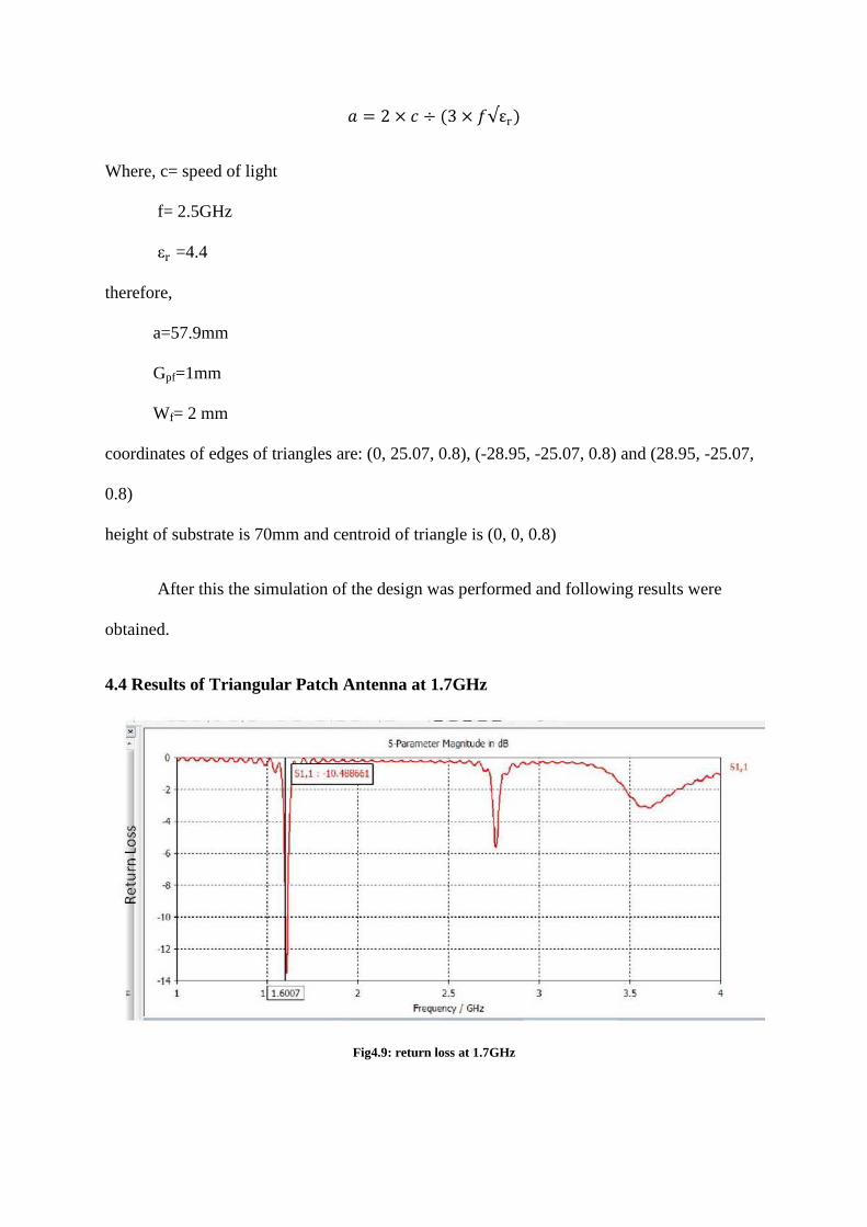
4.4 Results of Triangular Patch Antenna at 1.7GHz
Fig4.9: return loss at 1.7GHz

From this figure we get that it is a single band showing resonant frequency at 1.6GHz.
From graph after identifying -10dB line we get two points i.e. low and high frequency of
band.
Here we get, low frequency= 1.5973GHz
high frequency =1.6121GHz
Therefore bandwidth improvement= 0.92%
Fig4.10: 3D plot of gain at 1.7GHz
Fig4.11: VSWR at 1.7GHz
Here VSWR is 1.865 and it should be less than 2.
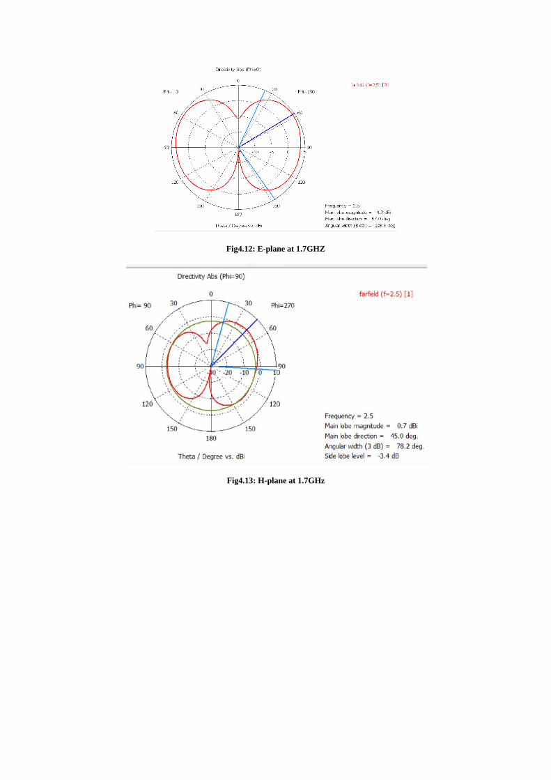
Fig4.12: E-plane at 1.7GHZ
Fig4.13: H-plane at 1.7GHz

Fig4.14: Cartesian plot of directivity
4.5 COMPARISON OF RECTANGULAR AND TRIANGULAR PATCH
SINGLE PATCH
ANTENNA
RESONANT
FREQUENCY
RETURN
LOSS
VSWR BANDWIDTH
IMPROVEMENT
(%)
DIRECTIVITY
RECTANGULAR
PATCH
ANTENNA
1.6 GHz -15 dB 1.42 1.49% 6.245dBi
TRIANGULAR
PATCH
ANTENNA
1.6 GHz -13 dB 1.86 0.92% 2.456 dBi
The triangular patch antenna configuration is chosen because it has the advantage of
occupying less metalized area on substrate than other existing configurations rectangular and
circular geometries are most commonly used, Its dimension that tends to be small can make
the overall dimension of the antenna very small too.
Resonant frequency of both antennas is 1.6 GHz; these are suitable for ISM and
WLAN.
Rectangular patch antenna:- low profile, light weight antennas, most suitable for
aerospace and mobile applications.

Triangular patch antenna is smaller in size compared to rectangular .Directivity of
rectangular patch antenna is higher than triangular patch antenna.

CHAPTER 5
DESIGN OF
RECTANGULAR
AND TRIANGULAR
LINEAR ARRAY
ANTENNA AND
COMPARISON OF
RESUTLS

5.1) Rectangular array antenna
In certain applications, desired antenna may be achieved with a single microstrip antenna.
However, as in the case of microwave antenna, characteristics such as high gain, beam
scanning, or directivity are achieved only when discrete radiators are combined to form arrays.
A linear array consists of elements located finite distances apart along a straight line [9].
Design of linear 2×1 array
In order to make fair comparison, the same substrate used in single element(εr=4.4 and
thickness h=1.6mm) is used in the 2×1 array. Here we took frequency 1.7GHz in order to
determine the length and width of rectangle.
𝐿 = 𝑐 ÷ (2 × 𝑓𝑟√ε)
Substituting all the values we get L= 42 mm
𝑊 = (𝑐 ÷ 2 × 𝐹𝑟)√(2/(𝜀 + 1))
Substituting, we get W= 53mm
Finally we get simulate the following design.
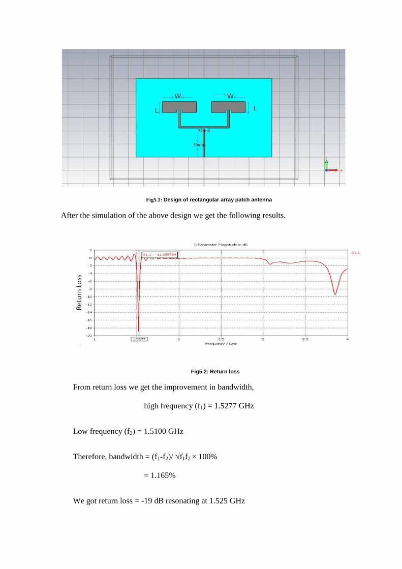
Fig5.1: Design of rectangular array patch antenna
After the simulation of the above design we get the following results.
Fig5.2: Return loss
From return loss we get the improvement in bandwidth,
high frequency (f1) = 1.5277 GHz
Low frequency (f2) = 1.5100 GHz
Therefore, bandwidth = (f1-f2)/ √f1f2 × 100%
= 1.165%
We got return loss = -19 dB resonating at 1.525 GHz
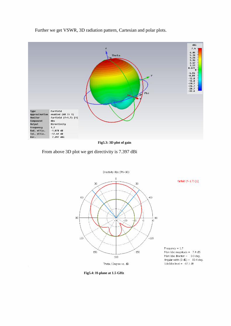
Further we get VSWR, 3D radiation pattern, Cartesian and polar plots.
Fig5.3: 3D plot of gain
From above 3D plot we get directivity is 7.397 dBi
Fig5.4: H-plane at 1.5 GHz

Fig5.5: E-plane at 1.5 GHz
Fig5.6: Cartesian plot of directivity
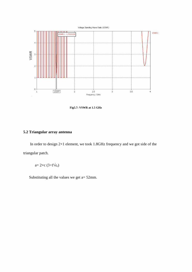
Fig5.7: VSWR at 1.5 GHz
5.2 Triangular array antenna
In order to design 2×1 element, we took 1.8GHz frequency and we got side of the
triangular patch.
a= 2×c (3×f√εr)
Substituting all the values we get a= 52mm.

The resulting 2×1 array is as follows:
Fig5.8: Design of 2×1 array element.
After the simulation we get the following results:
FIG 5.9: Return loss at 1.59 GHz.

Further we got VSWR, 3D, Cartesian and polar plot.
Fig5.10: H-plane at 1.59 GHz.
Fig5.11: E-plane at 1.59GHz.

Fig5.12: 3D plot of gain at 1.50GHz
Fig5.13: VSWR at 1.59GHz

5.3) Comparison between rectangular and triangular array patch antenna
From the results it is observed that the directivity of rectangular array antenna is better than
triangular array antenna and the directivity of rectangular array antenna is better than
rectangular patch antenna. İncreasing the number of elements increases the directivity. Hence
rectangular patch array antenna is preferred as it has maximum directivity and efficiency
among the antennas studied.
ARRAY PATCH
ANTENNA
RESONANT
FREQUENCY
RETURN
LOSS
VSWR BANDWIDTH
IMPROVEMENT
(%)
DIRECTIVITY
RECTANGULAR
PATCH ARRAY
ANTENNA
1.5277 GHz -19 Db 1.720 1.165% 7.397dBi
TRIANGULAR
PATCH ARRAY
ANTENNA
1.5692 GHz -15 dB 1.454 1.17% 5.187 dBi

CHAPTER 6
CONCLUSION

6. Conclusion The size of triangular shaped antenna is smaller but it is very difficult and time taking to
make the same, so we do not prefer this patch antenna. Because of directivity and wide
radiation pattern we prefer rectangular patch antenna.
In the case of arrays, directivity and radiation pattern improves with the increase in number of
elements and thus array is better than single element. On comparison between rectangular and
triangular shapes it can be concluded that the rectangular array antenna is the most efficient
of the simulated antennas.
6.1 Future work
Inorder to improve the directivity we can add more patches of antenna. So further we
can design 4×1 and 8×1 to improve the directivity.
In future other different type of feed techniques can be used to calculate the overall
performance of the antenna. Extensively and exclusively focusing on the area of different
design methods especially in enhancing the impedance bandwidth and the efficiency.

References:
1. Lo, Y.T., Solomon D. and Richards, W.F. “Theory and Experiment on Microstrip
Antennas,” IEEE Transactions on Antennas and Propagation, AP-27, 1979.
2. Bancroft, R. “Microstrip and Printed Antenna Design,” Noble Publishing 2004.
3. C. Bose, Collected Physical Papers. New York, N.Y.: Longmans, Green and Co., 1927.
4. Wolter Lemstra , Vic Hayes , John Groenewegen , The Innovation Journey of Wi-Fi: The
Road To Global Success, Cambridge University Press, 2010.
5. R. G. Vaughan and J. Bach Andersen, “Antenna diversity in mobile communications,” IEEE
Trans. Veh. Technol.,Vol. VT-36, No. 4, pp. 149-172, Nov. 1987.
6. Taga, T. Tsunekawa, K. and Saski, A., “Antennas for Detachable Mobile Radio
Units,” Review of the ECL, NTT, Japan, Vol. 35, No.1, January 1987.
7. Di Nallo, C.; Faraone, A., "Multiband internal antenna for mobile phones," Electronics
Letters, vol.41, no.9, pp. 514-515, 28 April 2005.
8. Y T Lo and S W Lee, editors, “Antenna Handbook Theory, Applications & Design’’, Van
Nostrand Rein Company, NY, 1988.
9. David M. Pozar and DanielH. Schaubert, “Microstrip Antennas: The Analysis and Design of
Microstrip Antennas and Arrays”, Wiley, 1995.
10. Rachmansyah, Antonius Irianto, and A. Benny Mutiara, “Designing and Manufacturing
Microstrip Antenna for Wireless Communication at 2.4 GHz,” International Journal of
Computer and Electrical Engineering, Vol. 3, No. 5, October 2011.


![WLAN Microstrip Patch Array Design[1]](https://img.pdfslide.net/doc/110x75/55cf9c9f550346d033aa770d/wlan-microstrip-patch-array-design1.jpg)