Embed Size (px)
Citation preview

Progress In Electromagnetics Research Letters, Vol. 10, 171–184, 2009
ULTRA-WIDEBAND AND MINIATURIZATION OF THEMICROSTRIP MONOPOLE PATCH ANTENNA (MMPA)WITH MODIFIED GROUND PLANE FOR WIRELESSAPPLICATIONS
D. N. Elsheakh
Hawaii Center for Advanced CommunicationsUniversity of HawaiiHonolulu, USA
H. A. Elsadek and E. A. Abdallah
Electronics Research InstituteCairo, Egypt
M. F. Iskander
Hawaii Center for Advanced CommunicationsUniversity of HawaiiHonolulu, USA
H. Elhenawy
Faculty of EngineeringAin Shams UniversityCairo, Egypt
Abstract—In this paper, ultra-wideband and miniaturization,technique for the microstrip monopole patch antenna (MMPA) inwireless applications is presented. Ultra-wideband was achieved byusing printed modified ground plane on a dielectric substrate with50Ω microstrip feed line. This technique allows the bandwidth of theMMPA to be ultra-wideband with satisfactory radiation propertiesand reduces the antenna size. The proposed antenna with modifiedground plane provides an impedance bandwidth (S11 < −10 dB)more than 5.5GHz corresponding to 116% of fundamental resonantfrequency with reduction in antenna size by 20% from original size.For further improvement in antenna characteristics, electromagnetic
Corresponding author: D. Elsheakh ([email protected]).
172 Elsheakh et al.
band-gap (EBG) structure is used. The surface wave was suppressedso the antenna bandwidth was increased to be 3–11 GHz correspondingto 170%, and the antenna size was reduced 43% of its originalsize. Two types of EBG are used. Holes are drilled around thepatch, and embedded circular patches of the electromagnetic band-gap structure with suitable dimension are used. Details of the proposedantenna design have been describe, and the typical experimental resultsare presented and discussed. Commercial software high frequencystructure simulator (HFSS R©) version 11 was used for the antennadesign.
1. INTRODUCTION
Recently, UWB has become a very promising wireless technology formany applications because of the attractive benefits it provides such asits resistance against jamming and multipath fading, low complexityand cost, power requirements and finally penetrating capability.According to the FCC the spectral mask of UWB for commercialapplications is of frequency band 3.1 to 10.6 GHz [1]. The design ofUWB antennas has received much attention in the research communityin recent years. Most of these designs use canonical elements such ascircles [2] or ellipses [3] for the radiating element. Combinations ofthese elements have also been used [4]. Printed monopole antennas aregood candidates for such systems because of its numerous advantagessuch as small size, lightweight, low profile, low cast, and ease ofintegration with other microwave components. It is being used inlarge variety of applications such as radar, missiles, aircraft, satellitecommunications, mobile communication base stations, handsets, aswell as in biomedical telemetry services [1]. However, these applicationsrequire wide bandwidth. There are numerous and well-known methodsto increase the bandwidth of the antennas including the use of substratethickness, low dielectric substrate, various impedance matching andfeeding techniques [3], multiple resonators [4–6], and slot antennageometry [7–9]. There has been extensive research on the antennabroadband and size reduction of microstrip monopole antennas [9, 10].However, conventional UWB antennas in the geometry of either logperiodic or spiral tend to be dispersive. They usually radiate differentfrequency components from different parts of the antenna, whichdistorts and stretches out the radiated waveform [3]. In wirelessapplications, the ground plane is an integral part of the antennastructure. In convention, MMPA shrinkage of the extended groundplate is an essential step for overall size reduction of antenna.
Progress In Electromagnetics Research Letters, Vol. 10, 2009 173
In this paper, a modified ground plane (MGP) is used to produceUWB antenna. The effects of the modified ground plane geometrieson the antenna characteristics in terms of frequency domain andbandwidth are studied. Then, they are analyzed both numerically andexperimentally in order to understand the operation of the antenna. Ithas been demonstrated that the optimal design of this type of antennacan achieve an ultra wide bandwidth with satisfactory radiationproperties.
The second part of this paper uses electromagnetic band-gapstructure (EBG) for further improvement of antenna characteristicssuch as impedance matching and surface wave suppression. Theantenna bandwidth is increased. And by adding, inductive andcapacitive load, the electrical antenna size is reduced. EBG structurehas also been suggested under a broad terminology [12]. Severaltypes of EBG structures have been proposed to improve the MMPAperformance as drilling holes surrounded the antenna structure [13]and embedded EBG structure as shown in the following sections.
2. PROPOSED ANTENNA GEOMETRY
2.1. Microstrip Monopole Patch Antenna with ModifiedGround Plane
First part of this paper uses conventional microstrip monopole patchantenna (MMPA) with modified ground plane (MGP) to obtain UWBantenna and reduce the antenna size. The antenna design is startedwith printed conventional square ground plane on substrate RT/D6010 with dielectric constant 10.2 and dimension 20 mm× 20 mm. Thesubstrate height is 2.5 mm (0.08λg) guided wavelength at fundamentalfrequency 5.2 GHz, and the ground plane side length is 20mm.The dimensions of rectangular radiator patch are Wp×Lp equal to8× 6.5mm2 as shown in Figure 1(a), and the feed line is designedto provide 50 Ω feed width Wf at fundamental resonance frequency5.2GHz. Moreover, the feed length Lf was optimized to obtain thepossible bandwidth. Then the effects of the ground plane length onboth antenna resonant frequency and bandwidth are studied. Thelength Lg of the antenna ground plane is optimized to obtain maximumbandwidth at Lg equal to 0.32λg as shown in Figure 2(b).
Second step is modifying the shape of the ground plane as shownin Figure 1(c) to improve and decrease the bandwidth discontinuity aswell as reduce the antenna resonant frequency. The MGP has manyparameters as curved radius rg, Lgs and Ls. For MMPA, the groundplane serves as an impedance matching circuit. Consequently, it tunes
174 Elsheakh et al.
(a) (b) (c)
Figure 1. (a) MMPA with conventional ground plane with variablelength, (b) MMPA with reduced ground length and (c) MMPA withmodified ground plane.
(a) (b)
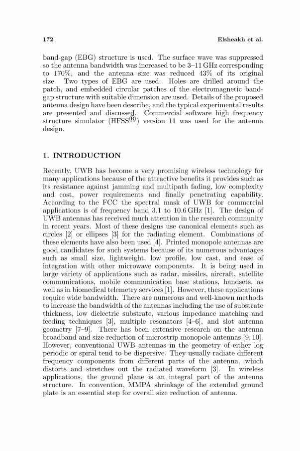
Figure 2. The proposed antenna elevation and side view (a) withsurrounded cylindrical holes, (b) with embedded EBG.
the input impedance and hence the 10 dB return loss bandwidth bychanging the feed length Lf . Another two important design parametersthat affect the antenna performance are the parameters of the groundplane as rg, Lgs and Ls and the dimensions of radiator patch Wp×Lp.
2.2. Microstrip Monopole Patch Antenna with EBGStructure
Second part of this paper uses electromagnetic band gap (EBG)structure to improve the antenna performance. Three principalcategories of such metamaterial have arisen and established. They arethe photonic bandgap (PBG), the electromagnetic band-gap (EBG)structures [9], and the double-negative materials. This paper is focusedon the second category mentioned above, namely the EBG structures.Cylindrical holes are drilled in the substrate surrounded the antennaradiator as shown in Figure 2(a) to prevent the surface wave to

Progress In Electromagnetics Research Letters, Vol. 10, 2009 175
propagate then improve the antenna bandwidth [14]. The radius ofthe drilling holes, r, was selected to improve the antenna performancein the frequency region where high reflections were observed. Thisso called “discontinuity region” occurs in the frequency range around10GHz as shown in Equation (1). Guided wavelength in the dielectricmaterial at 10 GHz is 9.3 mm, and this approximately equals theperiodicity P = 8 mm of the whole. This diameter d = 2r, however, issufficiently small to affect the antenna performance at lower frequenciesparticularly at the fundamental frequency of 5.2 GHz, and the distancebetween the drilling holes and the radiation patch are also optimized.
2d = λg (1)
where d, λg are the diameter of the drilling holes and the guidedwavelength, respectively.
Secondly embedded circular patches EBG structure are used tocreate band-gap that prevents electromagnetic wave to propagate inthe substrate and add additional inductive and capacitive load toimprove the matching impedance of MMPA. Different radiuses of thecircular embedded patches are used to create dual band-gap. Thishas been the first attempt to exploit the properties of the EBGsurface for antenna design and optimization. In this design, twodifferent radii patches are used with same periodicity P to achieve dualband-gap. This parameter is calculated from Equation (2) to obtainoptimum performance with inner via radius 0.25mm; the embeddedEBG structure is far from antenna radiator by 1.25mm as shown inFigure 2(b) [9].
2r/P = 0.9 ∼ 0.75 (2)
where r may be r1 or r2, and P is periodicity.Another interested property of EBG surfaces relates closely to the
reflection phase, i.e., the phase of the reflected electric-field intensity atthe reflecting surface, normalized by the phase of the incident electric-field intensity. It is well-known that a perfect electric conductor (PEC)presents reflection phase equal to 180 when a plane wave is normallyincident on it. In contrast to that phenomenon, the reflection phase ofa perfect magnetic conductor (PMC), which does not exist in nature, isequal to 0. EBG structures have been known to function in a way thatreminds of a PMC. Actually, the reflection phase of an EBG structuremay vary with frequency continuously, and because of that property,EBG surfaces can exhibit both PEC and PMC-like behaviors, albeitat different frequencies. Furthermore, the anisotropic characteristicsof EBG structures have been studied [14] and applied to the designof microstrip patch antenna as shown in Figure 2(b). The EBG used
176 Elsheakh et al.
in this antenna structure is two different sizes of circular patches tocreate staggered electromagnetic band-gap bands.
3. EXPERIMENTAL RESULTS DISCUSSION
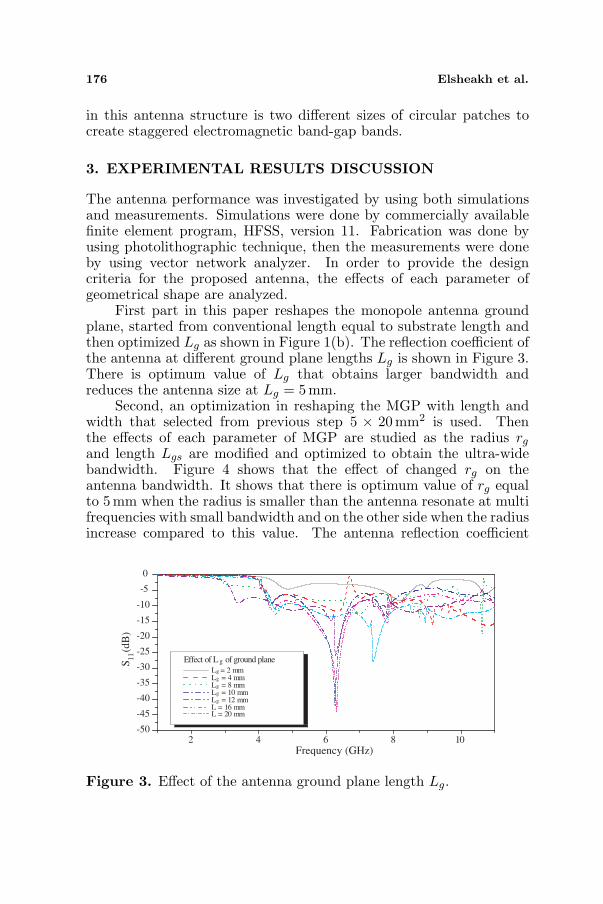
The antenna performance was investigated by using both simulationsand measurements. Simulations were done by commercially availablefinite element program, HFSS, version 11. Fabrication was done byusing photolithographic technique, then the measurements were doneby using vector network analyzer. In order to provide the designcriteria for the proposed antenna, the effects of each parameter ofgeometrical shape are analyzed.
First part in this paper reshapes the monopole antenna groundplane, started from conventional length equal to substrate length andthen optimized Lg as shown in Figure 1(b). The reflection coefficient ofthe antenna at different ground plane lengths Lg is shown in Figure 3.There is optimum value of Lg that obtains larger bandwidth andreduces the antenna size at Lg = 5mm.
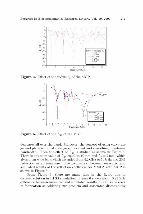
Second, an optimization in reshaping the MGP with length andwidth that selected from previous step 5 × 20mm2 is used. Thenthe effects of each parameter of MGP are studied as the radius rg
and length Lgs are modified and optimized to obtain the ultra-widebandwidth. Figure 4 shows that the effect of changed rg on theantenna bandwidth. It shows that there is optimum value of rg equalto 5 mm when the radius is smaller than the antenna resonate at multifrequencies with small bandwidth and on the other side when the radiusincrease compared to this value. The antenna reflection coefficient
2 4 6 8 10-50
-45
-40
-35
-30
-25
-20
-15
-10
-5
0
Frequency (GHz)
Effect of L g of ground plane
Lg = 2 mm Lg = 4 mm Lg = 8 mm Lg = 10 mm Lg = 12 mm L = 16 mm L = 20 mm
S11 (
dB
)
Figure 3. Effect of the antenna ground plane length Lg.
Progress In Electromagnetics Research Letters, Vol. 10, 2009 177
0 2 4 6 8 10 12-55
-50
-45
-40
-35
-30
-25
-20
-15
-10
-5
0
S1
1 (
dB
)
Frequency (GHz)
Effect of changing r g
3 mm 3.5 mm 4.5 mm 5 mm 5.5 mm 6 mm
Figure 4. Effect of the radius rg of the MGP.
-50
-40
-30
-20
-10
0
Effect of L gs
Lgs=7 mm Lgs=10 mm Lgs=13 mm
Frequency (GHz)2 3 4 5 6 7 8 9 10 11 12
S1
1 (
dB
)
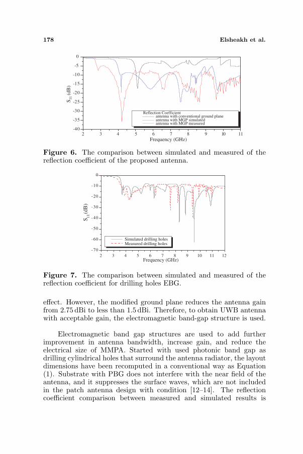
Figure 5. Effect of the Lgs of the MGP.
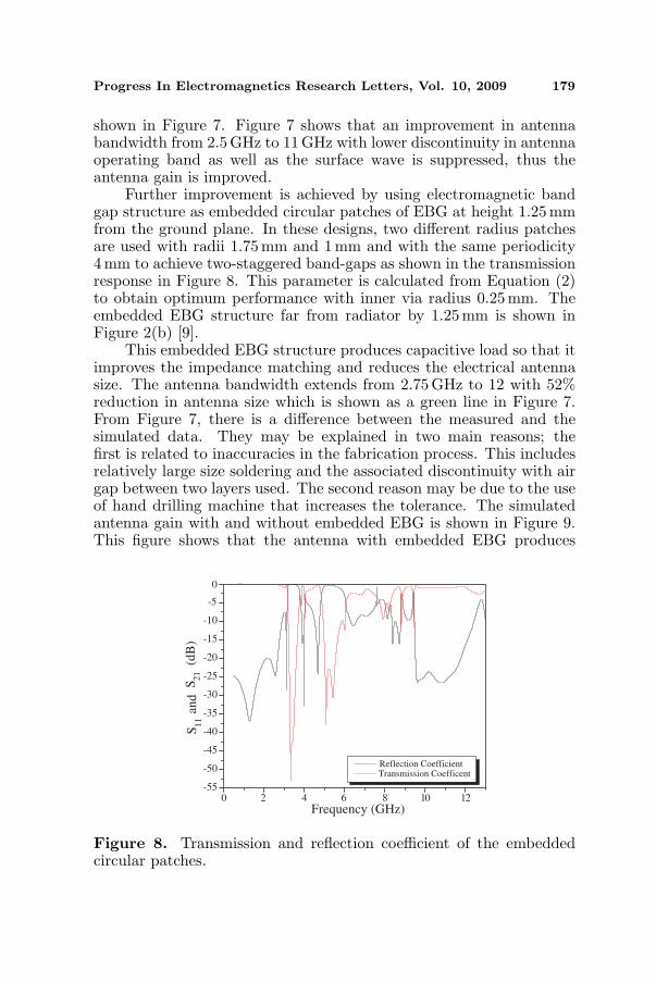
decreases all over the band. Moreover, the concept of using curvatureground plane is to make staggered resonant and smoothing in antennabandwidth. Then the effect of Lgs is studied as shown in Figure 5.There is optimum value of Lgs equal to 10 mm and Ls = 2 mm, whichgives ultra-wide bandwidth extended from 4.2 GHz to 10 GHz and 20%reduction in antenna size. The comparison between measured andsimulated results of the reflection coefficient for MMPA with MGP isshown in Figure 6.
From Figure 6, there are many dips in the figure due todiscreet solution in HFSS simulation. Figure 6 shows about 0.25GHzdifference between measured and simulated results, due to some errorin fabrication as soldering size problem and associated discontinuity
178 Elsheakh et al.
2 4 5 6 7 10 11-40
-35
-30
-25
-20
-15
-10
-5
0
Frequency (GHz)
Reflection Coefficientantenna with conventional ground planeantenna with MGP simulatedantenna with MGP measured
3 98
S11
(dB
)
Figure 6. The comparison between simulated and measured of thereflection coefficient of the proposed antenna.
2 3 4 5 6 7 8 9 10 11 12
-70
-60
-50
-40
-30
-20
-10
0
Frequency (GHz)
Simulated drilling holesMeasured drilling holes
S11 (
dB
)
Figure 7. The comparison between simulated and measured of thereflection coefficient for drilling holes EBG.
effect. However, the modified ground plane reduces the antenna gainfrom 2.75 dBi to less than 1.5 dBi. Therefore, to obtain UWB antennawith acceptable gain, the electromagnetic band-gap structure is used.
Electromagnetic band gap structures are used to add furtherimprovement in antenna bandwidth, increase gain, and reduce theelectrical size of MMPA. Started with used photonic band gap asdrilling cylindrical holes that surround the antenna radiator, the layoutdimensions have been recomputed in a conventional way as Equation(1). Substrate with PBG does not interfere with the near field of theantenna, and it suppresses the surface waves, which are not includedin the patch antenna design with condition [12–14]. The reflectioncoefficient comparison between measured and simulated results is
Progress In Electromagnetics Research Letters, Vol. 10, 2009 179
shown in Figure 7. Figure 7 shows that an improvement in antennabandwidth from 2.5 GHz to 11 GHz with lower discontinuity in antennaoperating band as well as the surface wave is suppressed, thus theantenna gain is improved.
Further improvement is achieved by using electromagnetic bandgap structure as embedded circular patches of EBG at height 1.25 mmfrom the ground plane. In these designs, two different radius patchesare used with radii 1.75 mm and 1 mm and with the same periodicity4mm to achieve two-staggered band-gaps as shown in the transmissionresponse in Figure 8. This parameter is calculated from Equation (2)to obtain optimum performance with inner via radius 0.25mm. Theembedded EBG structure far from radiator by 1.25 mm is shown inFigure 2(b) [9].
This embedded EBG structure produces capacitive load so that itimproves the impedance matching and reduces the electrical antennasize. The antenna bandwidth extends from 2.75 GHz to 12 with 52%reduction in antenna size which is shown as a green line in Figure 7.From Figure 7, there is a difference between the measured and thesimulated data. They may be explained in two main reasons; thefirst is related to inaccuracies in the fabrication process. This includesrelatively large size soldering and the associated discontinuity with airgap between two layers used. The second reason may be due to the useof hand drilling machine that increases the tolerance. The simulatedantenna gain with and without embedded EBG is shown in Figure 9.This figure shows that the antenna with embedded EBG produces
0 2 4 6 8 10 12-55
-50
-45
-40
-35
-30
-25
-20
-15
-10
-5
0
Reflection CoefficientTransmission Coefficent
Frequency (GHz)
S2
1 (
dB
)S
an
d1
1
Figure 8. Transmission and reflection coefficient of the embeddedcircular patches.
180 Elsheakh et al.
1 2 3 4 5 6 7 8 9 10 11 12-40
-35
-30
-25
-20
-15
-10
-5
0
S1
1 (
dB
)
Frequency (GHz)
Simulated EBG as Embeded circular shape
Measured EBG as Embeded circular shape
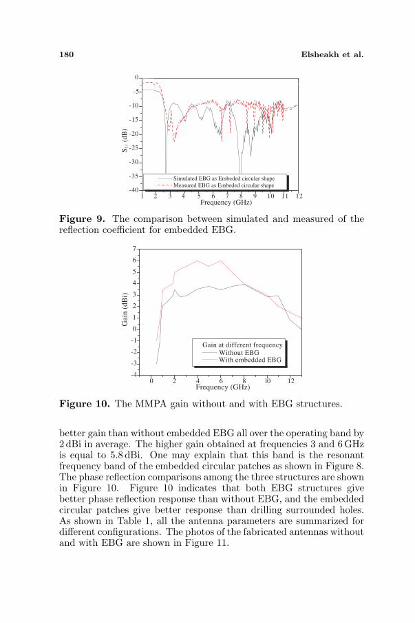
Figure 9. The comparison between simulated and measured of thereflection coefficient for embedded EBG.
0 2 4 6 8 10 12-4
-3
-2
-1
0
1
2
3
4
5
6
7
Gain at different frequency
Without EBG With embedded EBG
Frequency (GHz)
Gai
n (
dB
i)
Figure 10. The MMPA gain without and with EBG structures.
better gain than without embedded EBG all over the operating band by2 dBi in average. The higher gain obtained at frequencies 3 and 6GHzis equal to 5.8 dBi. One may explain that this band is the resonantfrequency band of the embedded circular patches as shown in Figure 8.The phase reflection comparisons among the three structures are shownin Figure 10. Figure 10 indicates that both EBG structures givebetter phase reflection response than without EBG, and the embeddedcircular patches give better response than drilling surrounded holes.As shown in Table 1, all the antenna parameters are summarized fordifferent configurations. The photos of the fabricated antennas withoutand with EBG are shown in Figure 11.

Progress In Electromagnetics Research Letters, Vol. 10, 2009 181
Table 1. The full proposed antenna design procedures.
Parameterizes Average gain (dBi) RadiationEfficiency Bandwidth
Full Ground 2.75 0.97% 3%Partial Ground 1.5 0.75% 78%
Surrounded Holes 2.5 0.8% 117%Embedded EBG 4.75 0.90% 200%
0 2 4 10-180
-150
-120
-9 0
-60
-30
0
30
60
90
120
150
180
Reflection Phase modified ground drilling holes embedded EBG
Frequency (GHz)86
Ref
lect
ion
ph
ase
(deg
ree)
Figure 11. Reflection phase for MMPA without and with EBGstructures.
Figure 12. The fabricated of the proposed antennas without and withEBG structures.
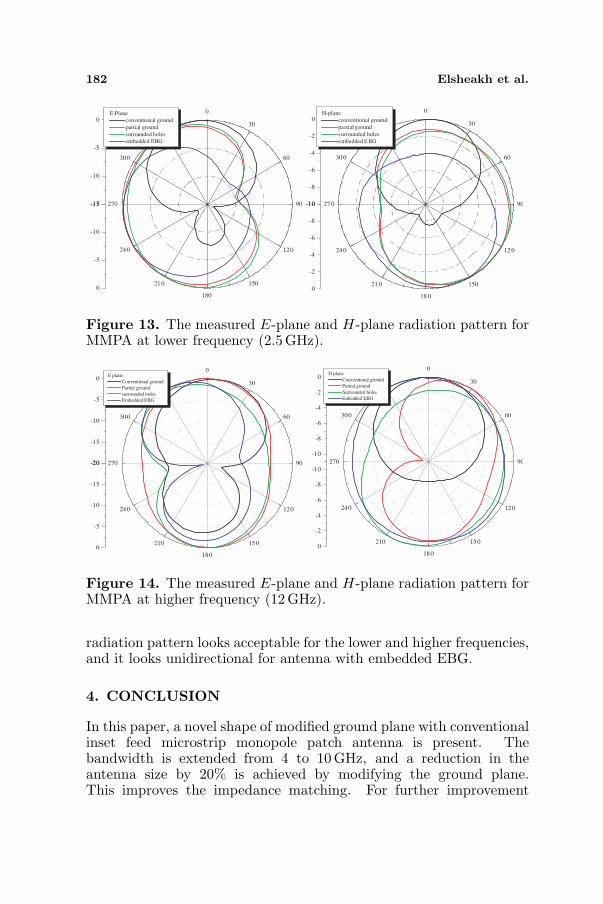
The different configurations of the proposed antennas aremeasured in both E- and H-planes, and this is shown in Figures 12and 13 for the lower and higher frequencies 2.5 and 12 GHz,respectively. Figure 12 shows the measured radiation pattern in E-and H-planes at lower frequency 2.5 GHz for conventional ground planeand the modified ground plane without and with EBG structures. The
182 Elsheakh et al.
-15
-10
-5
0
0
30
60
90
120
150
180
210
240
270
300
330
-15
-10
-5
0
E-Plane
conventional ground
partial ground
surrounded holes
embedded EBG
-10
-8
-6
-4
-2
0
0
30
60
90
12 0
150
18 0
21 0
24 0
27 0
30 0
33 0
-10
-8
-6
-4
-2
0
H-plane
conventional ground
partial ground
surrounded holes
embedded EBG
Figure 13. The measured E-plane and H-plane radiation pattern forMMPA at lower frequency (2.5 GHz).
-10
-8
-6
-4
-2
0
0
30
60
90
120
150
180
210
240
270
300
330
-10
-8
-6
-4
-2
0
H plane
Conventional ground
Partial ground
Surrounded holes
Enbedded EBG
-20
-15
-10
-5
0
0
30
60
90
120
150
180
210
240
270
300
330
-20
-15
-10
-5
0
E plane
Conventional ground
Partial ground
surrounded holes
Embedded EBG
Figure 14. The measured E-plane and H-plane radiation pattern forMMPA at higher frequency (12 GHz).
radiation pattern looks acceptable for the lower and higher frequencies,and it looks unidirectional for antenna with embedded EBG.
4. CONCLUSION
In this paper, a novel shape of modified ground plane with conventionalinset feed microstrip monopole patch antenna is present. Thebandwidth is extended from 4 to 10 GHz, and a reduction in theantenna size by 20% is achieved by modifying the ground plane.This improves the impedance matching. For further improvement
Progress In Electromagnetics Research Letters, Vol. 10, 2009 183
in the antenna parameters such as bandwidth, antenna size andgain, electromagnetic band-gap structure is used by drilling holesand embedding circular patches with different radii. The finalproposed antenna is MMPA with embedded circular patches. It usesdifferent radii to add additional capacitor that improves the impedancematching, obtains bandwidth extended from 2.5 GHz to 12 GHz withacceptable antenna gain 4.75 dBi, and reduces the electrical antennasize by 43% from the original one. The antenna phase reflection andradiation pattern in E- and H-planes are also presented.
REFERENCES
1. Ray, K. P., Y. Ranga, and P. Gabhale, “Printed square monopoleantenna with semicircular base for ultra-wide bandwidth,”Electronics Letters, Vol. 43, 13–14, 2007.
2. John, M. and M. J. Ammann, “Spline-based geometry for printedmonopole antennas,” Electronics Letters, Vol. 43, 7–8, 2007.
3. Liang, J., C. C. Chiau, X. Chen, and C. G. Parini, “Study of aprinted circular disc monopole antenna for UWB systems,” IEEETrans. on Antennas and Propag., Vol. 53, 3500–3504, 2005.
4. Wu, Q., R. Jin, J. Geng, and J. Lao, “Ultra-wideband rectangulardisk monopole antenna with notched ground,” Electronics Letters,Vol. 43, 605–606, 2007.
5. Liu, Z. D., P. S. Hall, and D. Wake, “Dual-frequency planar invert-F antenna,” IEEE Trans. on Antennas and Propag., Vol. 45, 1451–1457, 1997.
6. Kan, H. R. and R. B. Waterhouse, “Size reduction techniques forshorted patches,” Electronics Letters, Vol. 35, 948–949, 1999.
7. Nashaat, D., H. Elsadek, and H. Ghali, “Broad band U-shaped PlFA with dual band capability for bluetooth and WLANapplications,” Proceedings of IEEE International Symposium onAntenna and Propagation, Vol. 4, No. 1, January 2005.
8. Elsadek, H., and D. M. Nashaat, “Multiband and UWB V-shapedantenna configuration for wireless communications applications,”IEEE Antenna and Wireless Propagation Letters, Vol. 7, 2008.
9. Brown, E. R., C. D. Parker, and E. Yablonovitch, “Radiationproperties of a planar antenna on a photonic-crystal substrate,”Opt. Soc. Amer. B, Vol. 10, No. 2, 404–407, February 1993.
10. Matthew, M. B., B. B. John, O. E. Henry, et al., “Two dimensionalphotonic crystals fabry-perror resonators with loss dielectrics,”IEEE Trans. Microwave Theory Tech., Vol. 49, No. 11, 2085–2090,November 1999.

184 Elsheakh et al.
11. Gonzalo, R., P. Maaget, and M. Sorolla, “Enhanced patch antennaperformance by suppressing surface waves using photonic band-gap substrates,” IEEE Transaction on Microwave Theory andTechniques, Vol. 47, No. 11, 2131–2138, November 1999.
12. Mosallei, H. and K. Sarabandi, “Antenna miniaturization andbandwidth enhancement using a reactive impedance substrate,”IEEE Trans. on Antennas and Propag., Vol. 52, No. 9, September2004.
13. Hao, Y. and C. G. Paini, “Isolation enhancement of anisotropicUC-PBG microstrip diplexer patch antenna,” IEEE Antennas andWireless Propagation Letters, Vol. 1, 135–137, 2002.
14. Nashaat, D., H. A. Elsadek, E. Abdallah, H. Elhenawy, andM. F. Iskander, “Enhancement of ultra-wide bandwidth ofmicrostrip monopole antenna by using metamaterial structures,”IEEE Antenna and Wireless Propagation Letters, submitted,2009.