Embed Size (px)
Citation preview

(Plastic) Design Principles
SAFEICE Dissemination Workshop
25 September 2007
Richard Hayward
SAFEICE Dissemination Workshop | Kotka, 25 September 2007 | No. 2
Content
Presentation of results reported in :
Deliverable 8-4 Principles of Plastic Design
Deliverable 9-2 Assessment of Risk Levels in Ice
Class Rules
SAFEICE Dissemination Workshop | Kotka, 25 September 2007 | No. 3
Deliverable 8-4 Principles of Plastic Design
1. Why Plastic Design?2. Basic Collapse Mechanism3. Effect of Brackets4. Shear-Bending Interaction5. Shape Factors6. Energy Methods7. Acceptable Response Criteria?
SAFEICE Dissemination Workshop | Kotka, 25 September 2007 | No. 4
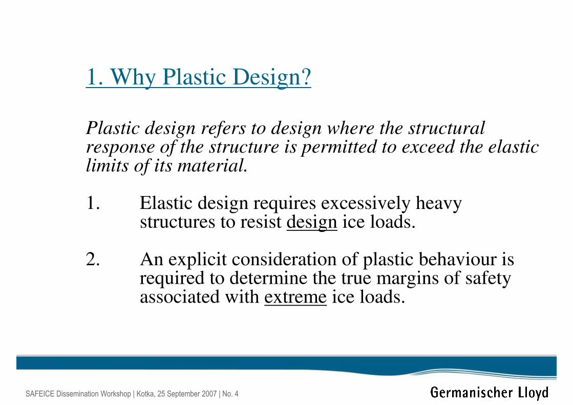
1. Why Plastic Design?
Plastic design refers to design where the structural response of the structure is permitted to exceed the elastic limits of its material.
1. Elastic design requires excessively heavy structures to resist design ice loads.
2. An explicit consideration of plastic behaviour is required to determine the true margins of safety associated with extreme ice loads.
SAFEICE Dissemination Workshop | Kotka, 25 September 2007 | No. 5
2/Yσσ = Yσσ =
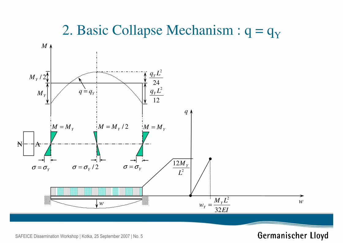
2. Basic Collapse Mechanism : q = qY
N A
EI
LMw Y
Y32
2
=w
q
YMM =
Yσσ =
2/YMM =YMM =
Yqq =
M
2
12
L
M Y
YM12
2LqY
24
2LqY
w
2/YM
SAFEICE Dissemination Workshop | Kotka, 25 September 2007 | No. 6
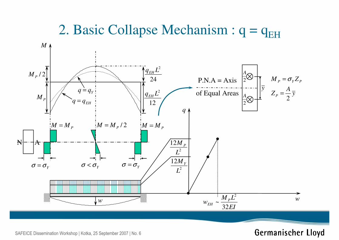
P.N.A = Axis
of Equal Areas
Yσσ < Yσσ =
2. Basic Collapse Mechanism : q = qEH
N A
EI
LMw P
EH32
~2
w
q
2
12
L
M P
PMM =
Yσσ =
2/PMM =PMM =
PMYqq =
EHqq =
M
2
12
L
M Y
yA
Z
ZM
P
PYP
2=
= σ
y
2
A
2
A
w
12
2LqEH
24
2LqEH2/PM
SAFEICE Dissemination Workshop | Kotka, 25 September 2007 | No. 7
EI
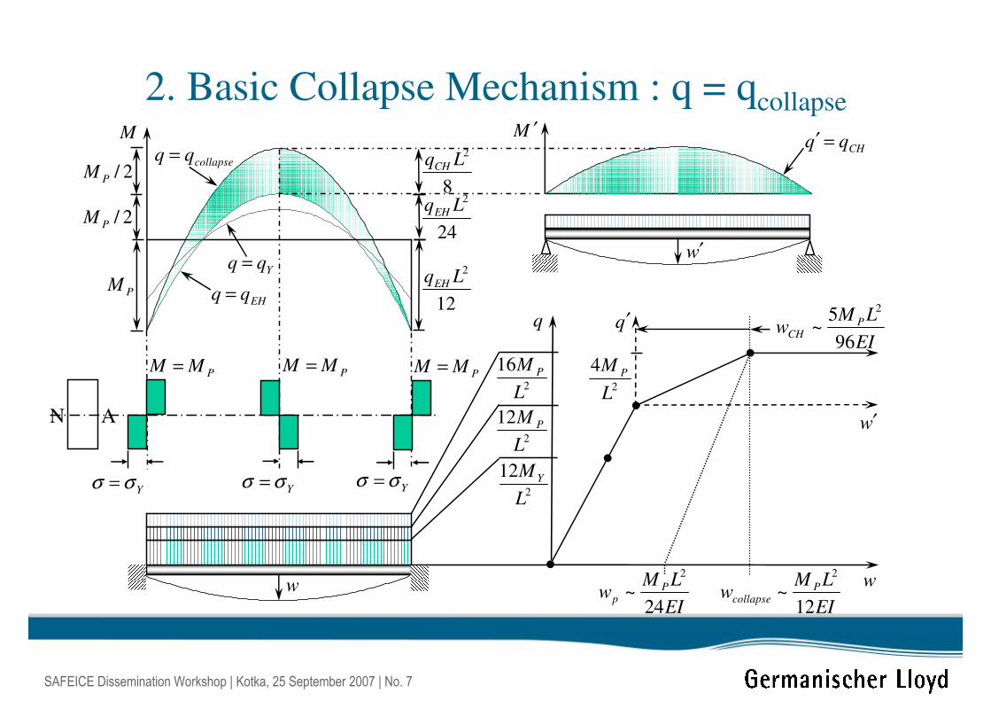
LMw P
CH96
5~
2
2. Basic Collapse Mechanism : q = qcollapse
N A
EI
LMw P
collapse12
~2
EI
LMw P
p24
~2
w′
w
q q′
2
4
L
M P
2
16
L
M P
2
12
L
M P
PMM =
Yσσ = Yσσ = Yσσ =
PMM =PMM =
Yqq =
EHqq =
collapseqq = CHqq =′M M ′
2
12
L
M Y
w
w′
2/PM
2/PM
PM
24
2LqEH
8
2LqCH
12
2LqEH
SAFEICE Dissemination Workshop | Kotka, 25 September 2007 | No. 8
Yσσ =Yσσ =
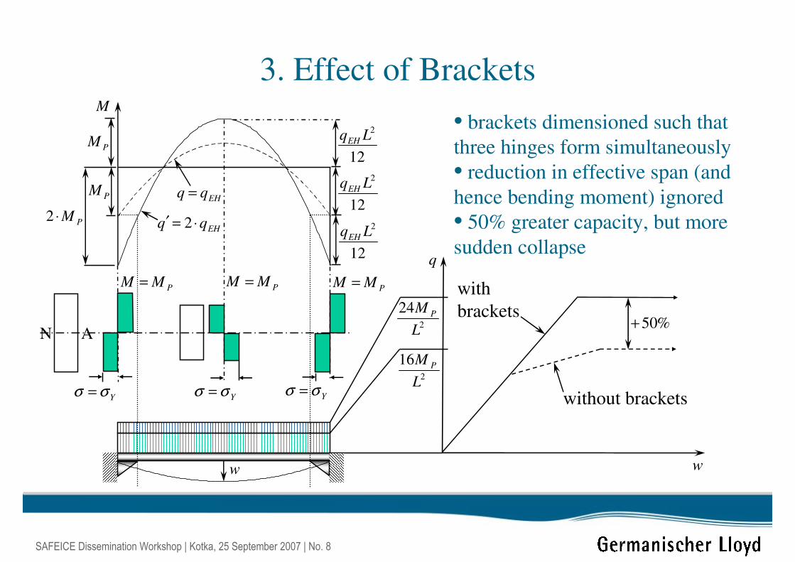
3. Effect of Brackets
N A
w
q
2
16
L
M P
PMM =
Yσσ =
PMM =PMM =
EHqq =
M
w
PM
12
2LqEHEHqq ⋅=′ 2PM⋅2
2
24
L
M P
%50+
PM12
2LqEH
12
2LqEH
• brackets dimensioned such that
three hinges form simultaneously
• reduction in effective span (and
hence bending moment) ignored
• 50% greater capacity, but more
sudden collapse
with
brackets
without brackets
SAFEICE Dissemination Workshop | Kotka, 25 September 2007 | No. 9
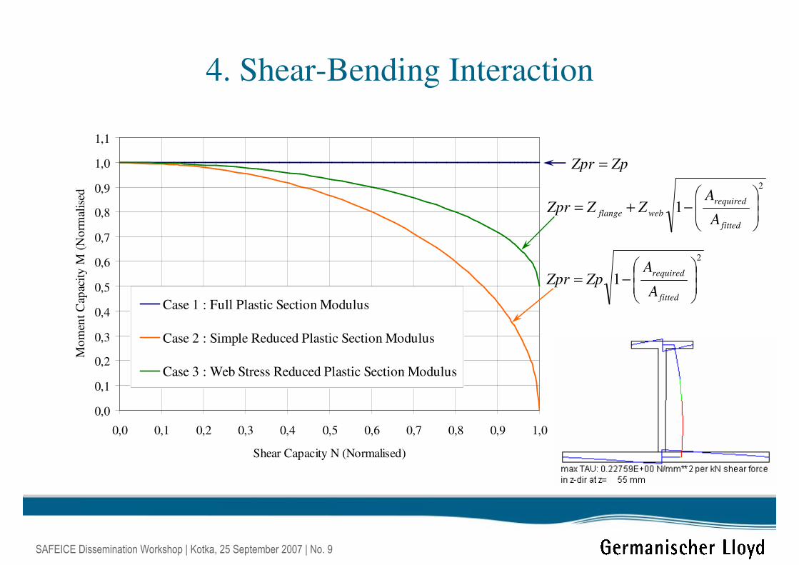
4. Shear-Bending Interaction
0,0
0,1
0,2
0,3
0,4
0,5
0,6
0,7
0,8
0,9
1,0
1,1
0,0 0,1 0,2 0,3 0,4 0,5 0,6 0,7 0,8 0,9 1,0
Shear Capacity N (Normalised)
Mo
men
t C
apac
ity
M (
No
rmal
ised
)
Case 1 : Full Plastic Section Modulus
Case 2 : Simple Reduced Plastic Section Modulus
Case 3 : Web Stress Reduced Plastic Section Modulus
ZpZpr =
2
1
−+=
fitted
required
webflangeA
AZZZpr
2
1
−=
fitted
required
A
AZpZpr
SAFEICE Dissemination Workshop | Kotka, 25 September 2007 | No. 10
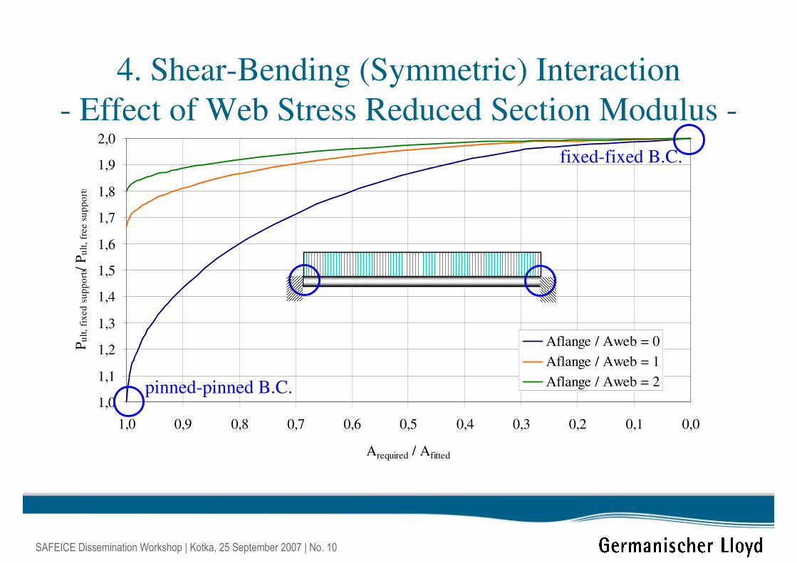
4. Shear-Bending (Symmetric) Interaction
- Effect of Web Stress Reduced Section Modulus -
1,0
1,1
1,2
1,3
1,4
1,5
1,6
1,7
1,8
1,9
2,0
0,00,10,20,30,40,50,60,70,80,91,0
Arequired / Afitted
Pu
lt,
fix
ed
su
pp
ort
s / P
ult
, fr
ee s
up
po
rts
Aflange / Aweb = 0
Aflange / Aweb = 1
Aflange / Aweb = 2pinned-pinned B.C.
fixed-fixed B.C.
SAFEICE Dissemination Workshop | Kotka, 25 September 2007 | No. 11
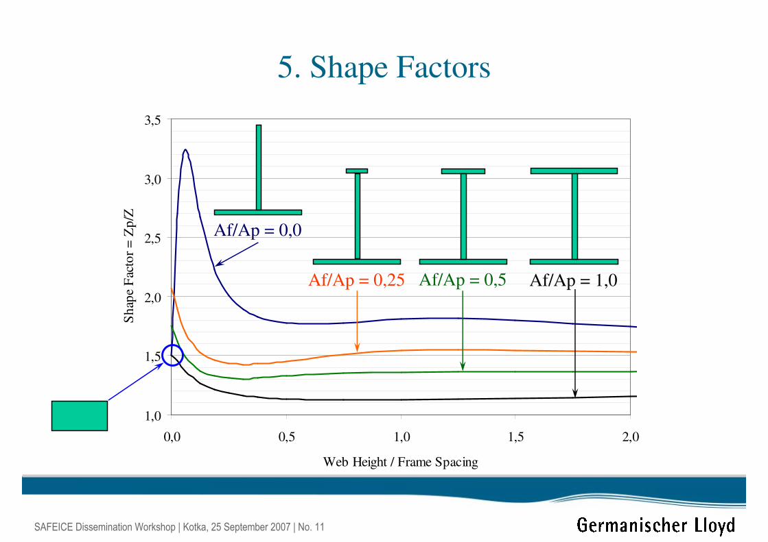
5. Shape Factors
1,0
1,5
2,0
2,5
3,0
3,5
0,0 0,5 1,0 1,5 2,0
Web Height / Frame Spacing
Sh
ape
Fac
tor
= Z
p/Z
Af/Ap = 0,0
Af/Ap = 1,0Af/Ap = 0,25 Af/Ap = 0,5
SAFEICE Dissemination Workshop | Kotka, 25 September 2007 | No. 12
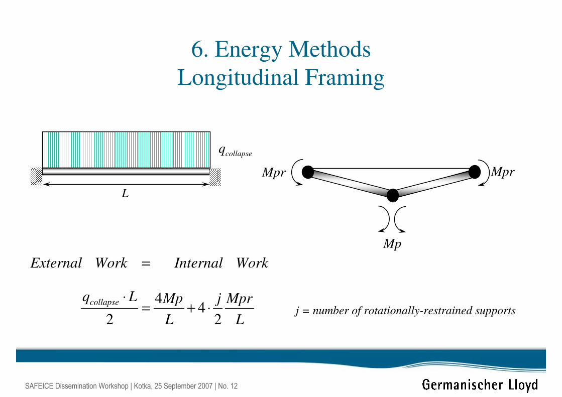
6. Energy Methods
Longitudinal Framing
WorkInternalWorkExternal =
Mp
MprMpr
L
collapseq
L
Mprj
L
MpLqcollapse
24
4
2⋅+=
⋅j = number of rotationally-restrained supports
SAFEICE Dissemination Workshop | Kotka, 25 September 2007 | No. 13
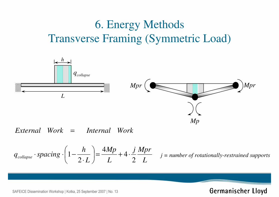
6. Energy Methods
Transverse Framing (Symmetric Load)
WorkInternalWorkExternal =
L
collapseq
j = number of rotationally-restrained supports
h
Mp
MprMpr
L
Mprj
L
Mp
L
hspacingqcollapse
24
4
21 ⋅+=
⋅−⋅⋅
SAFEICE Dissemination Workshop | Kotka, 25 September 2007 | No. 14
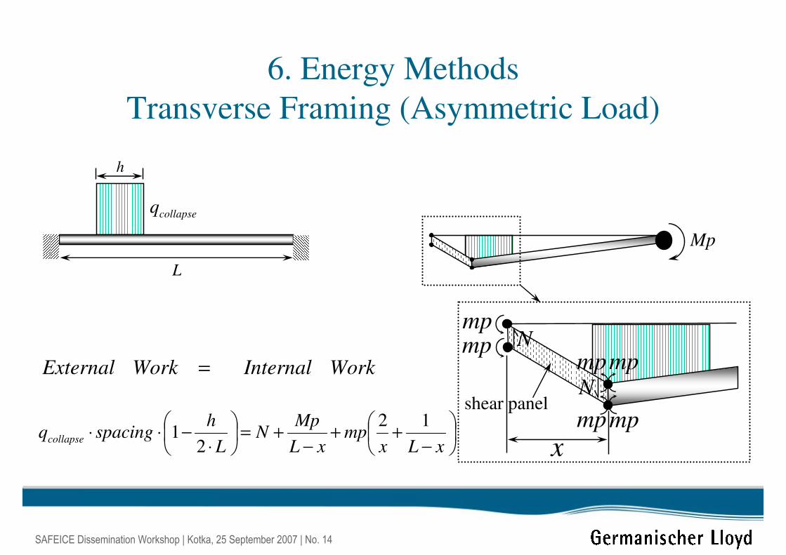
−++
−+=
⋅−⋅⋅
xLxmp
xL
MpN
L
hspacingqcollapse
12
21
6. Energy Methods
Transverse Framing (Asymmetric Load)
WorkInternalWorkExternal =
L
collapseq
Mp
h
x
mp
mp
mp
mp
Nmp
N
mp
shear panel
SAFEICE Dissemination Workshop | Kotka, 25 September 2007 | No. 15
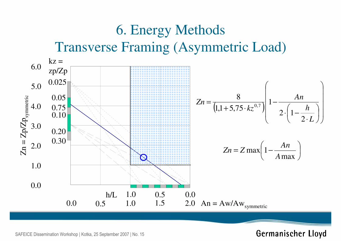
6. Energy Methods
Transverse Framing (Asymmetric Load)
h/L 0.00.51.0An = Aw/Awsymmetric0.0 0.5 1.0 1.5 2.0
Zn
= Z
p/Z
psy
mm
etr
ic
0.0
1.0
2.0
3.0
4.0
5.0
6.0kz =
zp/Zp
0.025
0.05
0.750.10
0.20
0.30
( )
⋅−⋅
−⋅+
=
L
h
An
kzZn
212
175,51,1
87,0
−=
max1max
A
AnZZn
SAFEICE Dissemination Workshop | Kotka, 25 September 2007 | No. 16
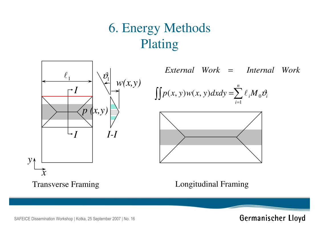
6. Energy Methods
Plating
WorkInternalWorkExternal =
∑∫∫=
=n
i
iiMdxdyyxwyxp1
0),(),( ϑl
w(x,y)1l 1ϑ
p (x,y)
x
y
I
I
I-I
Transverse Framing Longitudinal Framing
SAFEICE Dissemination Workshop | Kotka, 25 September 2007 | No. 17
7. Acceptable Response Criteria?
1. Ultimate or collapse limit state (ULS)
• based on load carrying capacity or
ultimate strength
2. Serviceability limit state (SLS)
• based on the limits of deflections (or
vibration) for normal use
SAFEICE Dissemination Workshop | Kotka, 25 September 2007 | No. 18
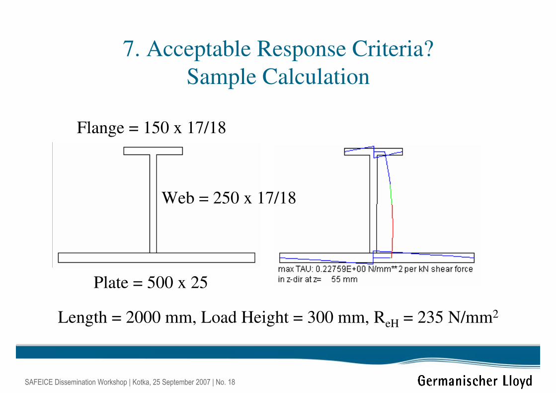
7. Acceptable Response Criteria?
Sample Calculation
Flange = 150 x 17/18
Web = 250 x 17/18
Plate = 500 x 25
Length = 2000 mm, Load Height = 300 mm, ReH = 235 N/mm2
SAFEICE Dissemination Workshop | Kotka, 25 September 2007 | No. 19
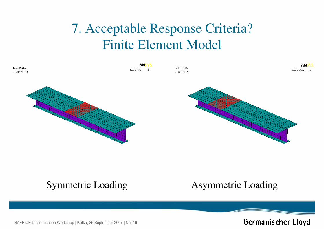
7. Acceptable Response Criteria?
Finite Element Model
Symmetric Loading Asymmetric Loading
SAFEICE Dissemination Workshop | Kotka, 25 September 2007 | No. 20
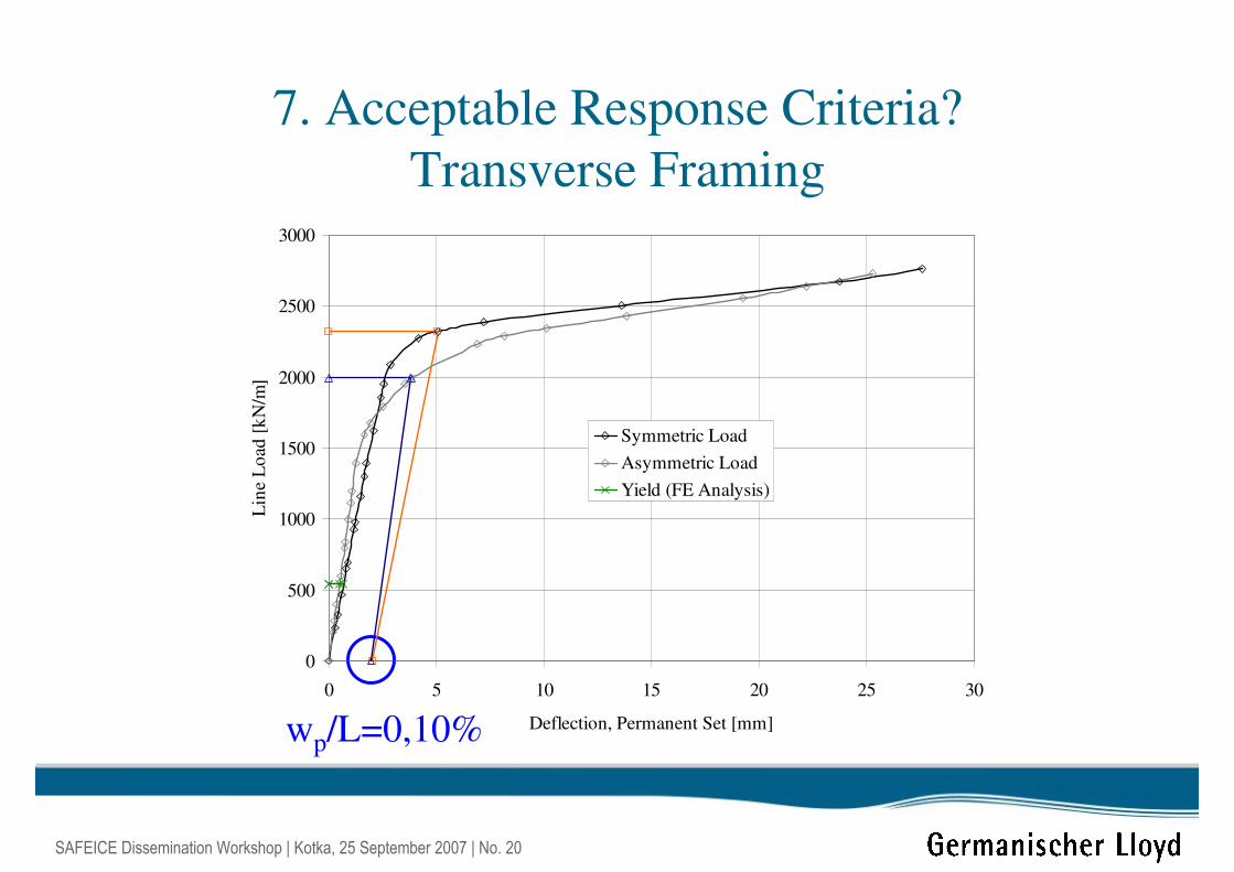
7. Acceptable Response Criteria?
Transverse Framing
wp/L=0,10%
0
500
1000
1500
2000
2500
3000
0 5 10 15 20 25 30
Deflection, Permanent Set [mm]
Lin
e L
oad
[k
N/m
]
Symmetric Load
Asymmetric Load
Yield (FE Analysis)
SAFEICE Dissemination Workshop | Kotka, 25 September 2007 | No. 21
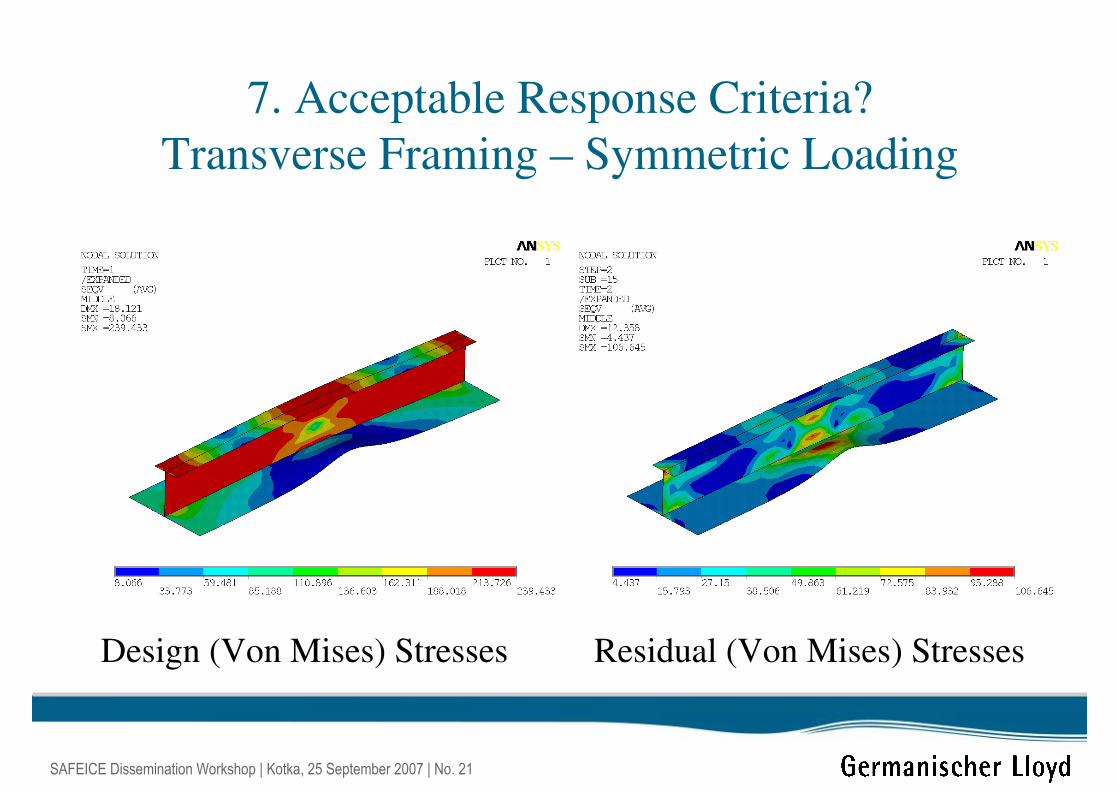
7. Acceptable Response Criteria?
Transverse Framing – Symmetric Loading
Design (Von Mises) Stresses Residual (Von Mises) Stresses
SAFEICE Dissemination Workshop | Kotka, 25 September 2007 | No. 22
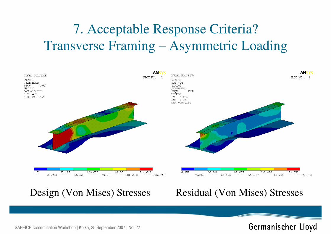
7. Acceptable Response Criteria?
Transverse Framing – Asymmetric Loading
Design (Von Mises) Stresses Residual (Von Mises) Stresses
SAFEICE Dissemination Workshop | Kotka, 25 September 2007 | No. 23
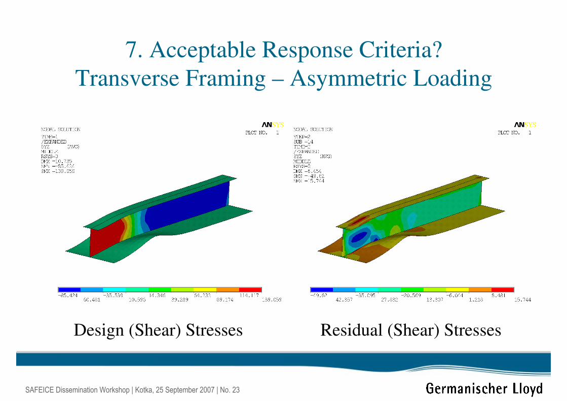
7. Acceptable Response Criteria?
Transverse Framing – Asymmetric Loading
Design (Shear) Stresses Residual (Shear) Stresses
SAFEICE Dissemination Workshop | Kotka, 25 September 2007 | No. 24
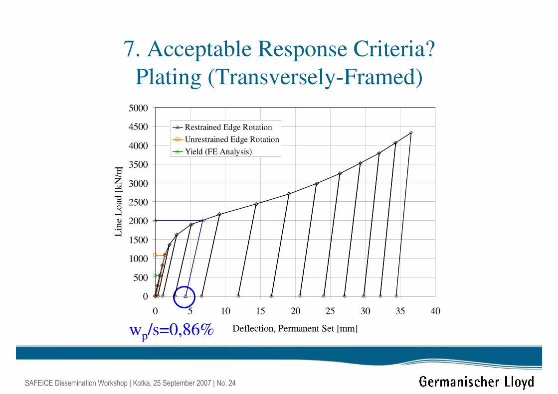
7. Acceptable Response Criteria?
Plating (Transversely-Framed)
wp/s=0,86%
0
500
1000
1500
2000
2500
3000
3500
4000
4500
5000
0 5 10 15 20 25 30 35 40
Deflection, Permanent Set [mm]
Lin
e L
oad
[k
N/m
]Restrained Edge Rotation
Unrestrained Edge Rotation
Yield (FE Analysis)
SAFEICE Dissemination Workshop | Kotka, 25 September 2007 | No. 25
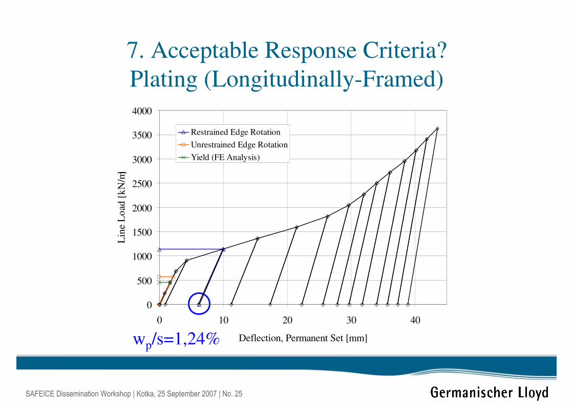
7. Acceptable Response Criteria?
Plating (Longitudinally-Framed)
wp/s=1,24%
0
500
1000
1500
2000
2500
3000
3500
4000
0 10 20 30 40
Deflection, Permanent Set [mm]
Lin
e L
oad
[k
N/m
]Restrained Edge Rotation
Unrestrained Edge Rotation
Yield (FE Analysis)
SAFEICE Dissemination Workshop | Kotka, 25 September 2007 | No. 26
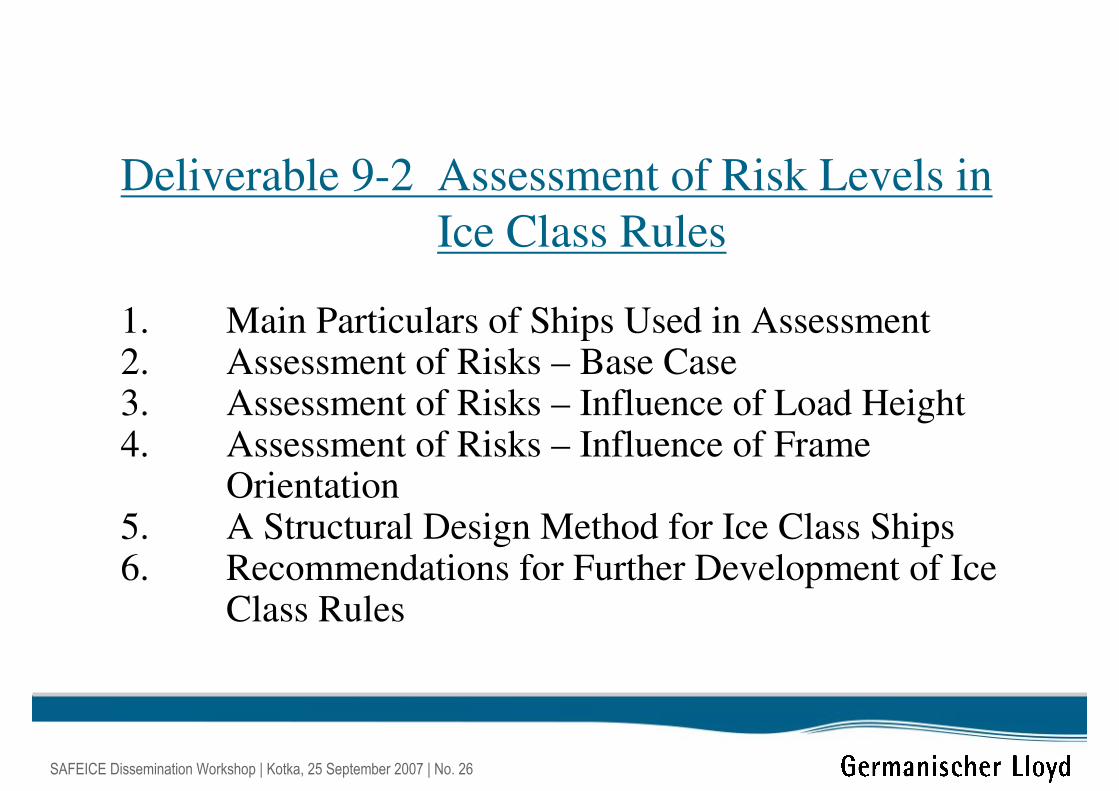
Deliverable 9-2 Assessment of Risk Levels in
Ice Class Rules
1. Main Particulars of Ships Used in Assessment2. Assessment of Risks – Base Case3. Assessment of Risks – Influence of Load Height4. Assessment of Risks – Influence of Frame
Orientation5. A Structural Design Method for Ice Class Ships6. Recommendations for Further Development of Ice
Class Rules
SAFEICE Dissemination Workshop | Kotka, 25 September 2007 | No. 27
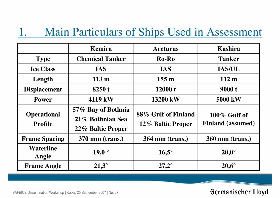
1. Main Particulars of Ships Used in Assessment
100% Gulf of
Finland (assumed)
88% Gulf of Finland
12% Baltic Proper
57% Bay of Bothnia
21% Bothnian Sea
22% Baltic Proper
Operational
Profile
20,6°27,2°21,3°Frame Angle
20,0°16,5°19,0 °Waterline
Angle
360 mm (trans.)364 mm (trans.)370 mm (trans.)Frame Spacing
5000 kW13200 kW4119 kWPower
9000 t12000 t8250 tDisplacement
112 m155 m113 mLength
IAS/ULIASIASIce Class
TankerRo-RoChemical TankerType
KashiraArcturusKemira

SAFEICE Dissemination Workshop | Kotka, 25 September 2007 | No. 28
2. Assessment of Risks
Base Case
Frame Spacing = 365 mm
Fra
me
Sp
an =
5 x
36
5 m
m σy = 235 N/mm2
Aflange/Aweb =0,50
kz = zp/Zp = 0,05
Afitted/Arequired = 1,0
Shape Factor = 1,25 (FSICR)
B.C. = Fixed-Fixed
Load Height = 300 mm
SAFEICE Dissemination Workshop | Kotka, 25 September 2007 | No. 29
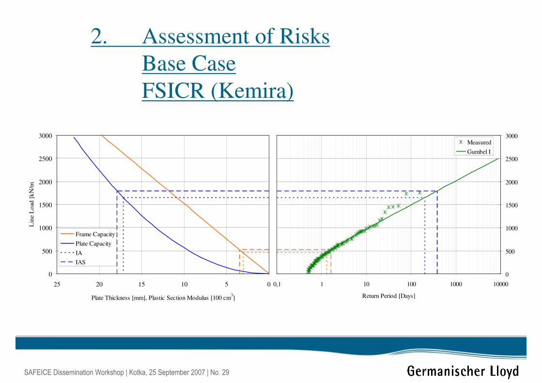
2. Assessment of Risks
Base Case
FSICR (Kemira)
0510152025
Plate Thickness [mm], Plastic Section Modulus [100 cm3]
0
500
1000
1500
2000
2500
3000
Lin
e L
oad
[k
N/m
]
Frame Capacity
Plate Capacity
IA
IAS
0,1 1 10 100 1000 10000
Return Period [Days]
0
500
1000
1500
2000
2500
3000Measured
Gumbel I
SAFEICE Dissemination Workshop | Kotka, 25 September 2007 | No. 30
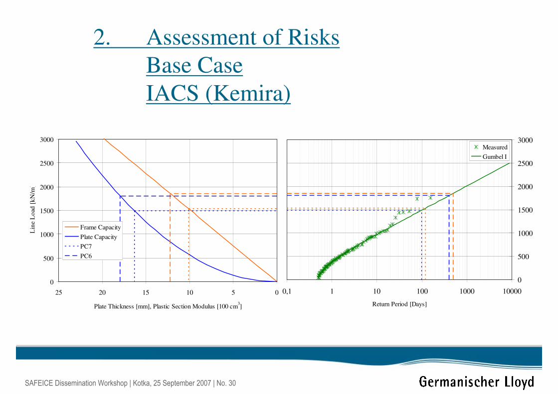
2. Assessment of Risks
Base Case
IACS (Kemira)
0510152025
Plate Thickness [mm], Plastic Section Modulus [100 cm3]
0
500
1000
1500
2000
2500
3000
Lin
e L
oad
[k
N/m
]
Frame Capacity
Plate Capacity
PC7
PC6
0,1 1 10 100 1000 10000
Return Period [Days]
0
500
1000
1500
2000
2500
3000Measured
Gumbel I
SAFEICE Dissemination Workshop | Kotka, 25 September 2007 | No. 31
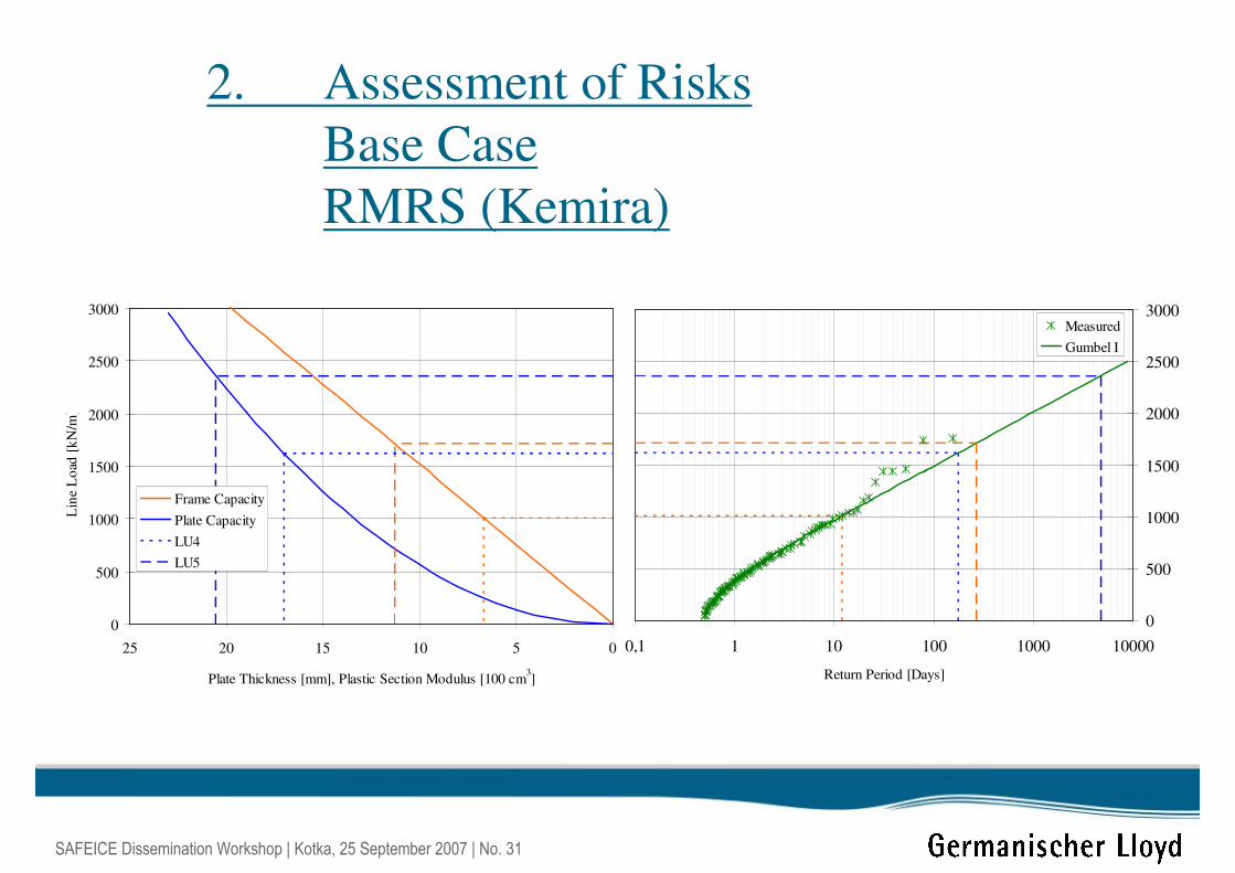
2. Assessment of Risks
Base Case
RMRS (Kemira)
0510152025
Plate Thickness [mm], Plastic Section Modulus [100 cm3]
0
500
1000
1500
2000
2500
3000
Lin
e L
oad
[k
N/m
]
Frame Capacity
Plate Capacity
LU4
LU5
0,1 1 10 100 1000 10000
Return Period [Days]
0
500
1000
1500
2000
2500
3000Measured
Gumbel I
SAFEICE Dissemination Workshop | Kotka, 25 September 2007 | No. 32
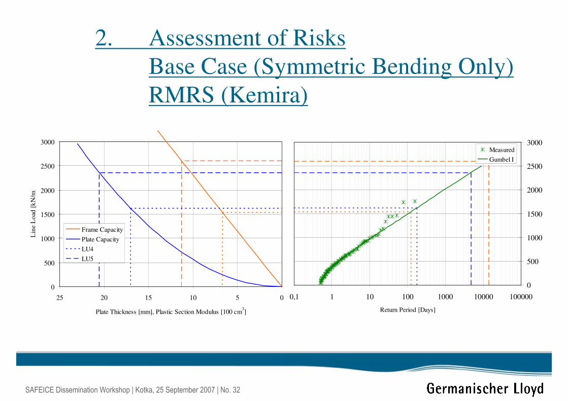
2. Assessment of Risks
Base Case (Symmetric Bending Only)
RMRS (Kemira)
0510152025
Plate Thickness [mm], Plastic Section Modulus [100 cm3]
0
500
1000
1500
2000
2500
3000
Lin
e L
oad
[k
N/m
]
Frame Capacity
Plate Capacity
LU4
LU5
0,1 1 10 100 1000 10000 100000
Return Period [Days]
0
500
1000
1500
2000
2500
3000Measured
Gumbel I
SAFEICE Dissemination Workshop | Kotka, 25 September 2007 | No. 33
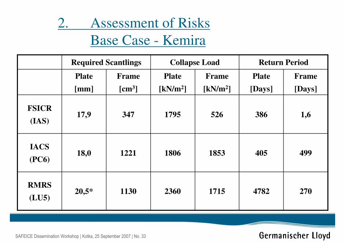
2. Assessment of Risks
Base Case - Kemira
270478217152360113020,5* RMRS
(LU5)
49940518531806122118,0IACS
(PC6)
1,6386526179534717,9FSICR
(IAS)
Frame
[Days]
Plate
[Days]
Frame
[kN/m2]
Plate
[kN/m2]
Frame
[cm3]
Plate
[mm]
Return PeriodCollapse LoadRequired Scantlings
SAFEICE Dissemination Workshop | Kotka, 25 September 2007 | No. 34
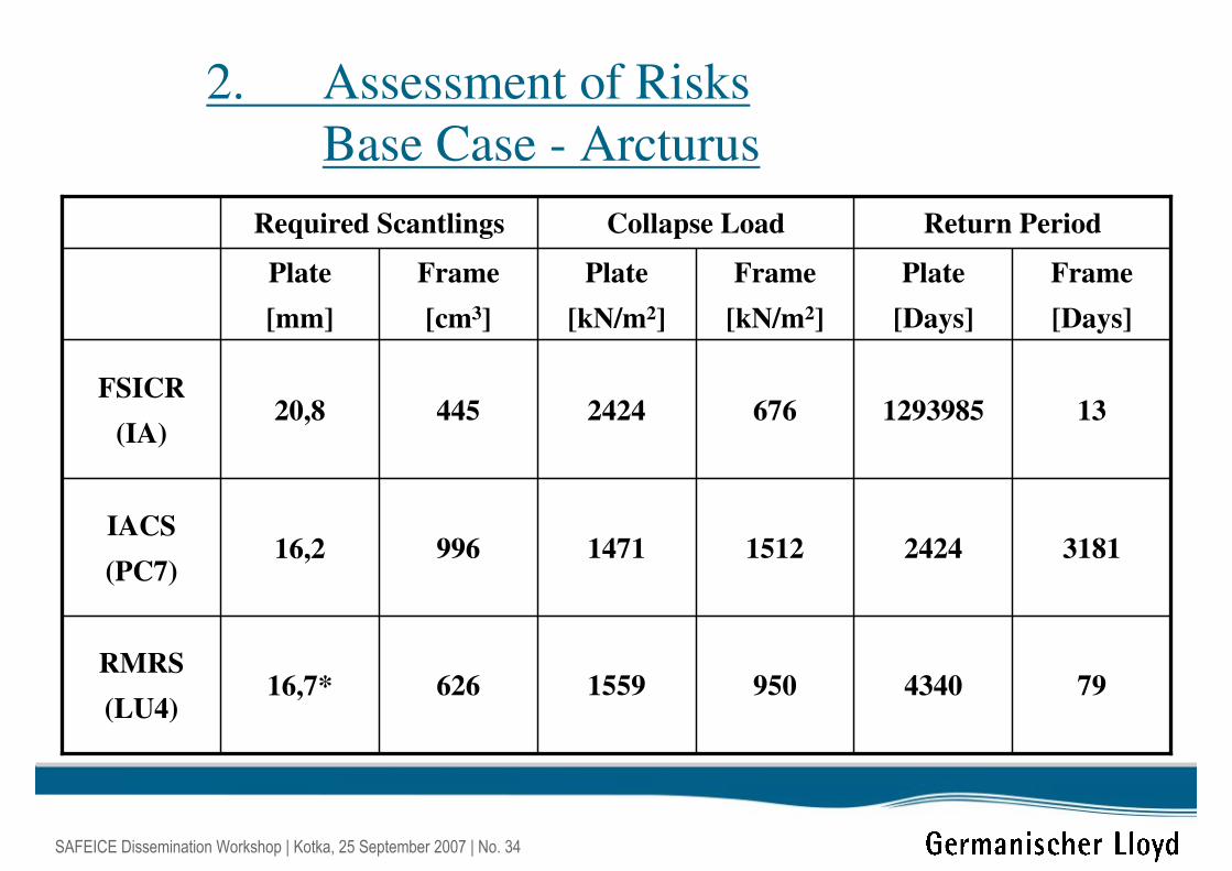
2. Assessment of Risks
Base Case - Arcturus
794340950155962616,7*RMRS
(LU4)
318124241512147199616,2IACS
(PC7)
131293985676242444520,8FSICR
(IA)
Frame
[Days]
Plate
[Days]
Frame
[kN/m2]
Plate
[kN/m2]
Frame
[cm3]
Plate
[mm]
Return PeriodCollapse LoadRequired Scantlings
SAFEICE Dissemination Workshop | Kotka, 25 September 2007 | No. 35
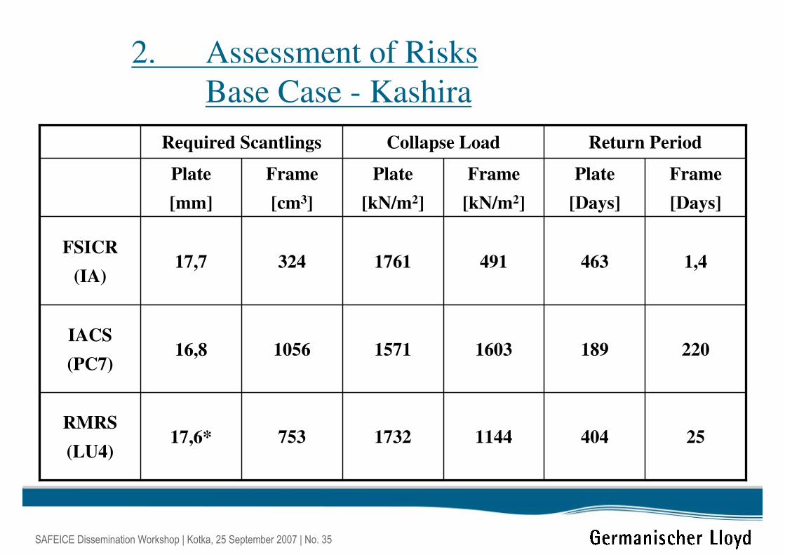
2. Assessment of Risks
Base Case - Kashira
254041144173275317,6*RMRS
(LU4)
22018916031571105616,8IACS
(PC7)
1,4463491176132417,7FSICR
(IA)
Frame
[Days]
Plate
[Days]
Frame
[kN/m2]
Plate
[kN/m2]
Frame
[cm3]
Plate
[mm]
Return PeriodCollapse LoadRequired Scantlings
SAFEICE Dissemination Workshop | Kotka, 25 September 2007 | No. 36
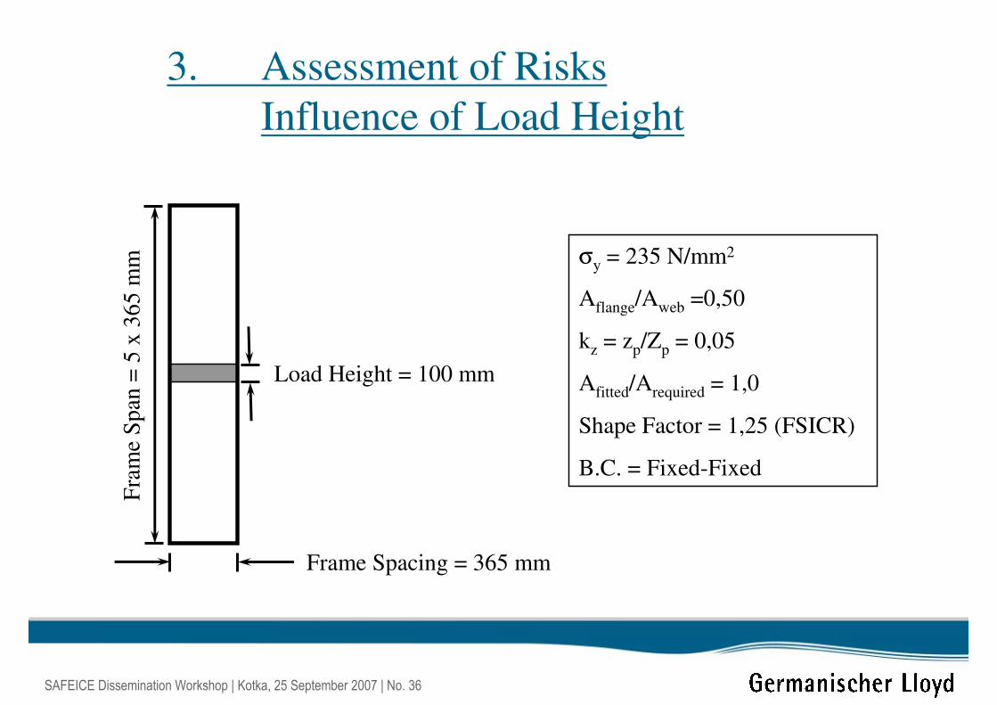
3. Assessment of Risks
Influence of Load Height
Frame Spacing = 365 mm
Fra
me
Sp
an =
5 x
36
5 m
m σy = 235 N/mm2
Aflange/Aweb =0,50
kz = zp/Zp = 0,05
Afitted/Arequired = 1,0
Shape Factor = 1,25 (FSICR)
B.C. = Fixed-Fixed
Load Height = 100 mm
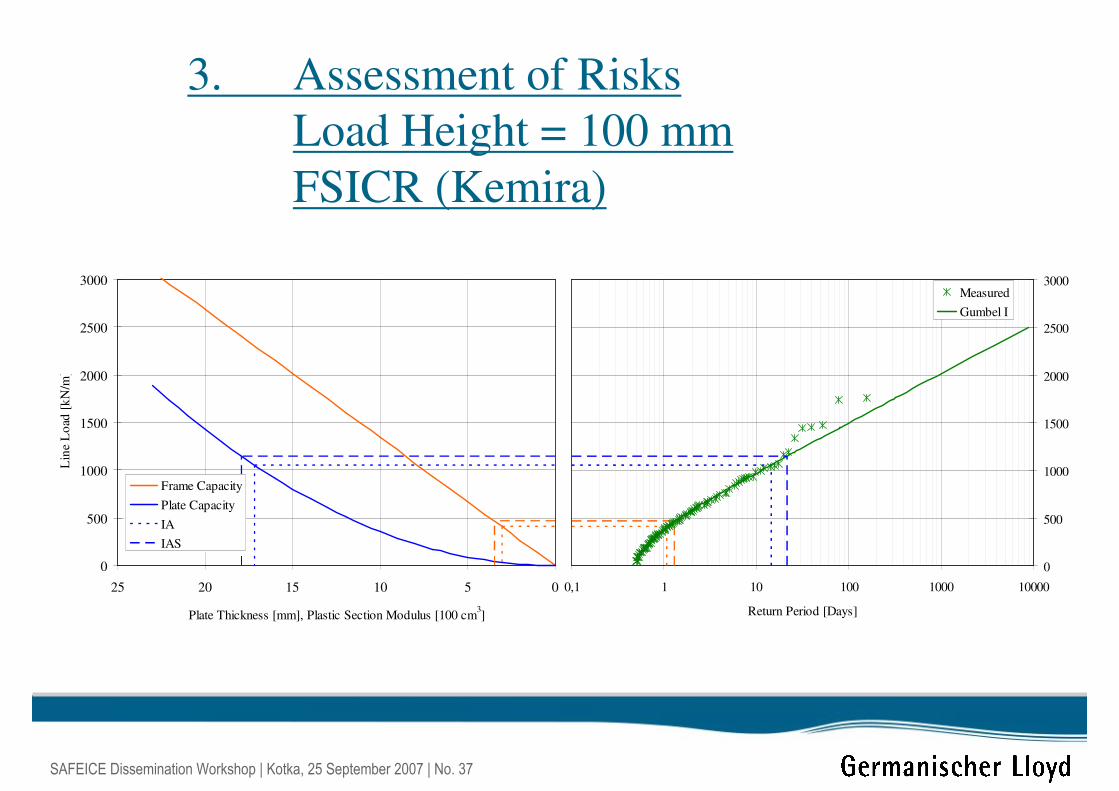
SAFEICE Dissemination Workshop | Kotka, 25 September 2007 | No. 37
3. Assessment of Risks
Load Height = 100 mm
FSICR (Kemira)
0510152025
Plate Thickness [mm], Plastic Section Modulus [100 cm3]
0
500
1000
1500
2000
2500
3000
Lin
e L
oad
[k
N/m
]
Frame Capacity
Plate Capacity
IA
IAS
0,1 1 10 100 1000 10000
Return Period [Days]
0
500
1000
1500
2000
2500
3000Measured
Gumbel I
SAFEICE Dissemination Workshop | Kotka, 25 September 2007 | No. 38
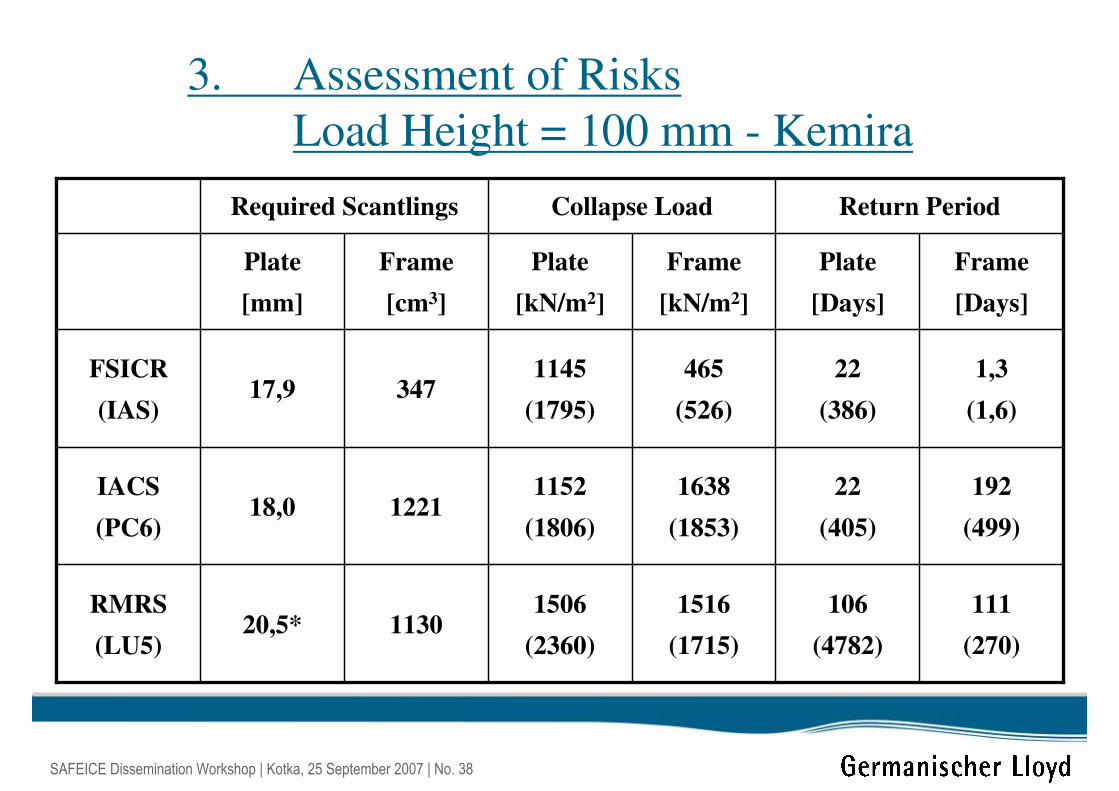
3. Assessment of Risks
Load Height = 100 mm - Kemira
111
(270)
106
(4782)
1516
(1715)
1506
(2360)113020,5*
RMRS
(LU5)
192
(499)
22
(405)
1638
(1853)
1152
(1806)122118,0
IACS
(PC6)
1,3
(1,6)
22
(386)
465
(526)
1145
(1795)34717,9
FSICR
(IAS)
Frame
[Days]
Plate
[Days]
Frame
[kN/m2]
Plate
[kN/m2]
Frame
[cm3]
Plate
[mm]
Return PeriodCollapse LoadRequired Scantlings
SAFEICE Dissemination Workshop | Kotka, 25 September 2007 | No. 39
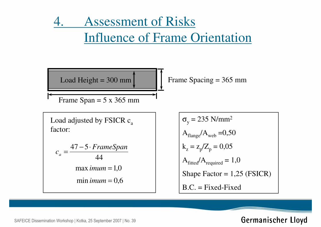
4. Assessment of Risks
Influence of Frame Orientation
Frame Spacing = 365 mm
Frame Span = 5 x 365 mm
σy = 235 N/mm2
Aflange/Aweb =0,50
kz = zp/Zp = 0,05
Afitted/Arequired = 1,0
Shape Factor = 1,25 (FSICR)
B.C. = Fixed-Fixed
Load Height = 300 mm
Load adjusted by FSICR ca
factor:
44
547 FrameSpanca
⋅−=
0,1max =imum
6,0min =imum
SAFEICE Dissemination Workshop | Kotka, 25 September 2007 | No. 40
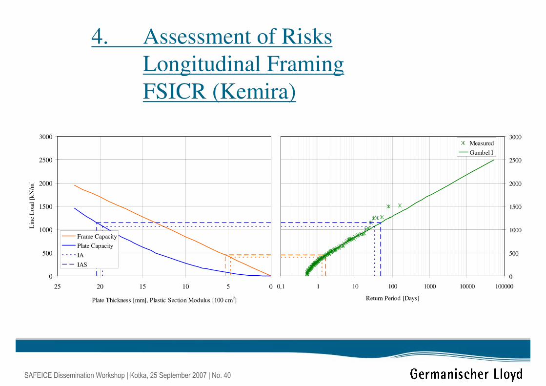
4. Assessment of Risks
Longitudinal Framing
FSICR (Kemira)
0510152025
Plate Thickness [mm], Plastic Section Modulus [100 cm3]
0
500
1000
1500
2000
2500
3000
Lin
e L
oad
[k
N/m
]
Frame Capacity
Plate Capacity
IA
IAS
0,1 1 10 100 1000 10000 100000
Return Period [Days]
0
500
1000
1500
2000
2500
3000Measured
Gumbel I
SAFEICE Dissemination Workshop | Kotka, 25 September 2007 | No. 41
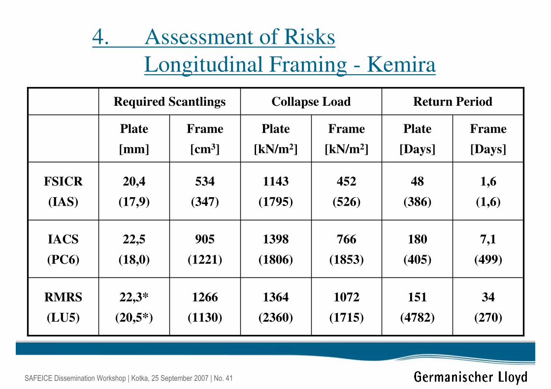
4. Assessment of Risks
Longitudinal Framing - Kemira
34
(270)
151
(4782)
1072
(1715)
1364
(2360)
1266
(1130)
22,3*
(20,5*)
RMRS
(LU5)
7,1
(499)
180
(405)
766
(1853)
1398
(1806)
905
(1221)
22,5
(18,0)
IACS
(PC6)
1,6
(1,6)
48
(386)
452
(526)
1143
(1795)
534
(347)
20,4
(17,9)
FSICR
(IAS)
Frame
[Days]
Plate
[Days]
Frame
[kN/m2]
Plate
[kN/m2]
Frame
[cm3]
Plate
[mm]
Return PeriodCollapse LoadRequired Scantlings
SAFEICE Dissemination Workshop | Kotka, 25 September 2007 | No. 42
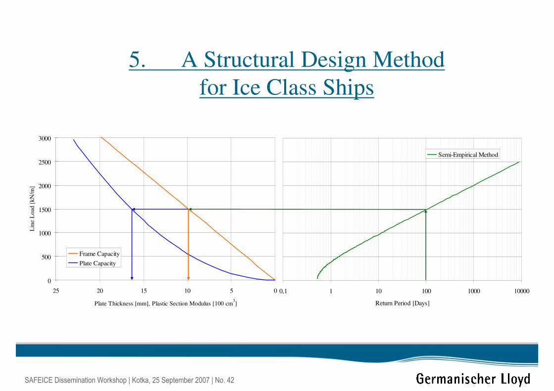
5. A Structural Design Method
for Ice Class Ships
0510152025
Plate Thickness [mm], Plastic Section Modulus [100 cm3]
0
500
1000
1500
2000
2500
3000
Lin
e L
oad
[kN
/m]
Frame Capacity
Plate Capacity
0,1 1 10 100 1000 10000
Return Period [Days]
Semi-Empirical Method
SAFEICE Dissemination Workshop | Kotka, 25 September 2007 | No. 43
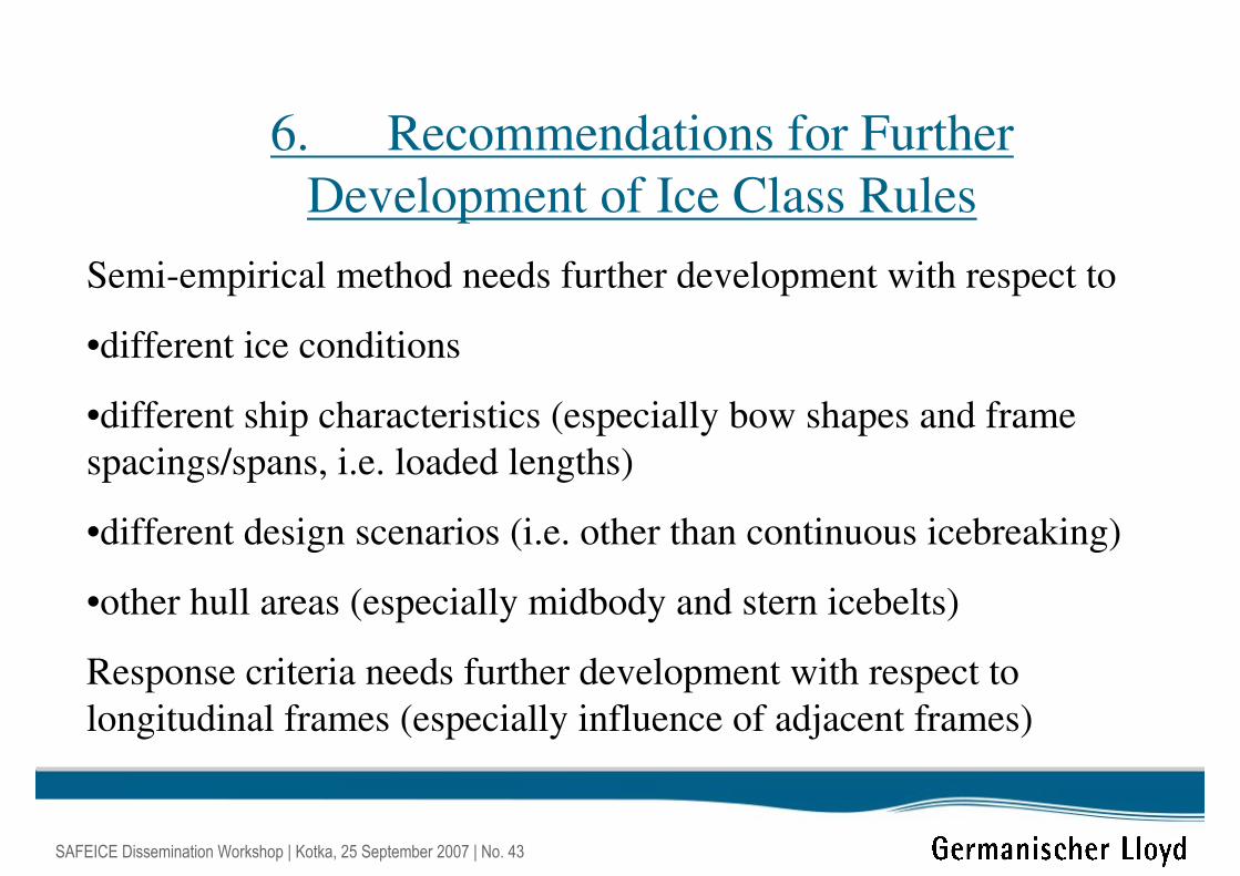
6. Recommendations for Further
Development of Ice Class Rules
Semi-empirical method needs further development with respect to
•different ice conditions
•different ship characteristics (especially bow shapes and frame
spacings/spans, i.e. loaded lengths)
•different design scenarios (i.e. other than continuous icebreaking)
•other hull areas (especially midbody and stern icebelts)
Response criteria needs further development with respect to
longitudinal frames (especially influence of adjacent frames)
(Plastic) Design Principles
SAFEICE Dissemination Workshop
25 September 2007
Richard Hayward