Embed Size (px)
Citation preview

ENGR 6806 – Motor Control
Prepared By: Rob Collett
September 15, 2004
Email: [email protected]
Office: EN2074

Presentation Outline
Introduction Motor Basics H-Bridges Using The PIC for Motor Control Motor Encoders Grounding Conclusions and Recommendations

1.0 IntroductionWhat Not to Think…
“Our team already has a motor guy… this should be good time to take a nap.”
“Some of this stuff is theory… why is this guy wasting my time with that?”
“I don’t have a clue what he’s talking about.”

2.0 Motor Basics
Pop Quiz: A motor is like a(n)…A) Resistor
B) Capacitor
C) Inductor
D) Crazy space-aged device we aren’t really meant to
understand

The Answer Is…(Not D) C) An Inductor!!… sort of…

The Problem: What’s wrong with the circuit
below?

Well, think about it… An inductor is a short circuit at DC!
This means we’ll have an infinite current! Infinite current = Infinite Speed!!

Get to the Point… A motor is like a REAL inductor…
not an IDEAL inductor.
It has resistance!

Remember this Waveform! Note how the current levels off. This will provide a steady speed.
RL
eR
Vs
R
Vsti
t
)(
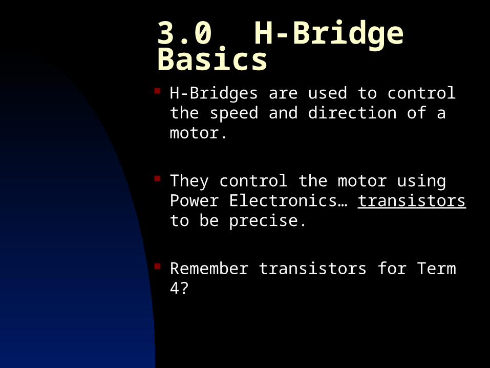
3.0 H-Bridge Basics H-Bridges are used to control the
speed and direction of a motor.
They control the motor using Power Electronics… transistors to be precise.
Remember transistors for Term 4?

For $1,000,000:What’s a Transistor?
Transistors are electronic devices that can act as either: Amplifiers Switches
We’ll be using them as switches that control the flow of power to the motor.
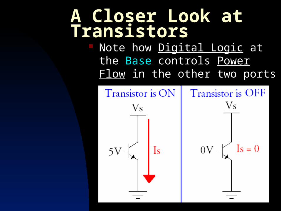
A Closer Look at Transistors Note how Digital Logic at the Base
controls Power Flow in the other two ports

Controlling Motor Speed
By turning our transistors (switches) ON and OFF really fast, we change the average voltage seen by the motor.
This technique is called
Pulse-Width Modulation (PWM).

PWM Basics The higher the voltage seen by the
motor, the higher the speed.
We’ll manipulate the PWM
Duty Cycle.

The Problem with PWM… Remember our little talk about
motors? Remember that motors are like
inductors? Remember this waveform?

What’s the Problem? If we switch our transistors too
quickly, the current won’t have enough time to increase.

The Solution: The period (not to be confused
with duty cycle) of our PWM needs to be long enough for the current to reach an acceptable level:

Direction Control using the H-Bridge
The H-Bridge Chip has a “Direction Pin” that can be set using digital logic High/Low
This pin enables/disables flow through the transistors

The H-Bridge Chip The H-Bridge we’re using (the
LMD18200) has 11 pins
Some pins involve logic signals, others involve power signals, others won’t be connected
Power signals = No breadboard No breadboard = Soldering
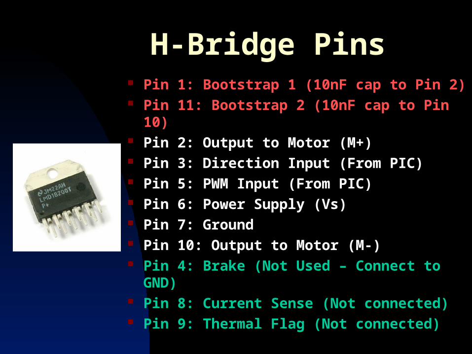
H-Bridge Pins Pin 1: Bootstrap 1 (10nF cap to Pin 2) Pin 11: Bootstrap 2 (10nF cap to Pin 10) Pin 2: Output to Motor (M+) Pin 3: Direction Input (From PIC) Pin 5: PWM Input (From PIC) Pin 6: Power Supply (Vs) Pin 7: Ground Pin 10: Output to Motor (M-) Pin 4: Brake (Not Used – Connect to GND) Pin 8: Current Sense (Not connected) Pin 9: Thermal Flag (Not connected)

H-Bridge Wiring (From the Lab Handout)
But wait… There’s something missing!

Another Problem: We’re dealing with a high voltages
and currents that are being switched at high frequencies.
This is going to cause spiking in our power supply… not to mention a whack of noise.
Surely there must be some kind of component that prevents instantaneous changes in voltage.

Of Course! Capacitors!
Capacitors across the H-Bridge power supply will prevent spiking.
Two parallel capacitors are recommended: 200uF 1uf(Be sure to check voltage ratings)
Why two capacitors?
4.0 Using The PIC for Motor Control
We’ll use the PIC to generate digital logic signals to control our
H-Bridge transistors
So we’ll need A digital high/low for direction
output_high(PIN_A0); A PWM for speed control

Setting the PWM Signal This can be tough because we need
to use a timer to set the PWM frequency.
We also need to figure out how to control the PWM duty cycle.
This is going to take some programming!

Setting up a PWM Signal Step 1:
Tell the PIC we want a PWM signal: setup_ccp1(CCP_PWM);
Step 2:The PIC uses a timer called “Timer2” to control the PWM frequency. We need to set this frequency: setup_timer_2(T2_DIV_BY_X, Y, Z);
But what are X, Y, and Z? - See handout for example.

Setting up a PWM Signal
Step 3: We said before that setting the PWM
Duty Cycle will set the speed of the motor.
So, to start the motor, we could say: set_pwm1_duty(#); (0 < # < 100)
To stop the motor, we could say: set_pwm1_duty(0);

5.0 Motor Encoders Motor Encoders allow for us to
track how far our robot has travelled.
The encoders count wheel revolutions using optical sensors.
These sensors count notches on the Drive Shaft of the motor.

Some Encoder Details… There are 512 notches on the drive
shaft.
There is a 5.9:1 gear ratio. (This means the drive shaft spins 5.9x faster than the wheel.)
The top wheel speed is around 800rpm (using a 30V supply).
Some Electrical Details…
The encoders we’ll be using have 4 wires: 5V Power Supply (Red) GND (Black) Channel A a.k.a. CHA (Blue) Channel B a.k.a. CHB (Yellow)
Channels A&B will give us the signals to count wheel revolutions.

How Encoders Work CHA and CHB are actually square
waves separated by 900.

Counting Encoder Cycles So, if we know the current encoder
state and the last encoder state, we can tell which direction we’re going.
By counting the number of times we’ve changed states, we can tell how far we’ve gone.
Just remember that there are 4 encoder states per notch!

6.0 Grounding Advice What is “Ground”? What is “Ground” on a Robot?
Power Supply Grounds Batteries and Grounding
Use a Grounding Panel! Attach your Panel to your Robot!!

Conclusions and Recommendations Help is here if you need it.
[email protected] EN 2074
“My robot isn’t working perfectly.”
Don’t let your robot take years off your life!
Good Luck!


![[Charles T. Collett, Christopher D. Robson] Handbo(Bookos.org)](https://img.pdfslide.net/doc/110x75/5466d345af795969338b538d/charles-t-collett-christopher-d-robson-handbobookosorg.jpg)

![[6806 - 17350]Mecanica I Midiateca](https://img.pdfslide.net/doc/110x75/55cf8c505503462b138b59c2/6806-17350mecanica-i-midiateca.jpg)