Embed Size (px)
Citation preview

Design Review Pre-Read P07310: Polaris ESMT
RIT Senior Design I 2/16/2007
Jason Botterill – ME, Team Lead Richard Cheng – EE
Vaibhav Kothari – ISE Yi Fan Zhang – ME
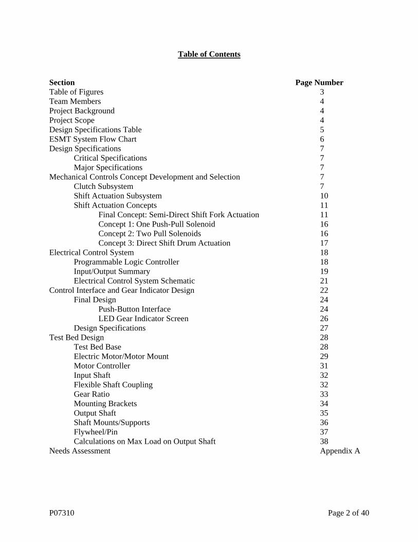
Table of Contents Section Page Number Table of Figures 3 Team Members 4 Project Background 4 Project Scope 4 Design Specifications Table 5 ESMT System Flow Chart 6 Design Specifications 7 Critical Specifications 7 Major Specifications 7 Mechanical Controls Concept Development and Selection 7 Clutch Subsystem 7 Shift Actuation Subsystem 10 Shift Actuation Concepts 11 Final Concept: Semi-Direct Shift Fork Actuation 11 Concept 1: One Push-Pull Solenoid 16 Concept 2: Two Pull Solenoids 16 Concept 3: Direct Shift Drum Actuation 17 Electrical Control System 18 Programmable Logic Controller 18 Input/Output Summary 19 Electrical Control System Schematic 21 Control Interface and Gear Indicator Design 22 Final Design 24 Push-Button Interface 24 LED Gear Indicator Screen 26 Design Specifications 27 Test Bed Design 28 Test Bed Base 28 Electric Motor/Motor Mount 29 Motor Controller 31 Input Shaft 32 Flexible Shaft Coupling 32 Gear Ratio 33 Mounting Brackets 34 Output Shaft 35 Shaft Mounts/Supports 36 Flywheel/Pin 37 Calculations on Max Load on Output Shaft 38 Needs Assessment Appendix A
P07310 Page 2 of 40

List of Figures and Tables Figure /Table Page Number Cover Image: Polaris Outlaw 525 High-Performance ATV Cover Table 1: Design specifications 5 Figure 1: System flow chart 6 Figure 2: Clutch assembly drawing 8 Figure 3: Picture of assembled clutch 8 Figure 4: Picture of semi-assembled clutch 8 Figure 5: Rekluse Motor Sports z-Start Auto Clutch components 9 Figure 6: Internal view of shift drum 11 Figure 7: Shift drum removed from transmission 11 Figure 8: Model of new shift drum 12 Figure 9: Shift fork 12 Figure 10: Spur gear stepper motor 13 Figure 11: Stepper motor horn 14 Figure 12: Stepper motor/mounting assembly 15 Figure 13: Concept utilizing push/pull linear solenoid 16 Figure 14: Concept utilizing two pull solenoids 16 Figure 15: External view of shift drum 17 Table 2: AB 1760-L18DWD-EX specifications 18 Figure 16: Flowchart overview of program 19 Figure 17: Electrical control system schematic 21 Figure 18: Rider’s view on the Outlaw 525 22 Figure 19: Rider’s view of left hand controls 22 Figure 20: Rider’s view of right hand controls 23 Figure 21: Final gear control design 24 Figure 22: Final gear control design, alternate view 25 Figure 23: Final gear control design, multi-view with dimensions 25 Figure 24: Current status indictor display on the Outlaw 525 26 Figure 25: Modified display with gear indicator 26 Figure 26: Modified display dimensions 27 Table 3: Control interface design specifications 27 Figure 27: Test bed layout 28 Figure 28: Motor mount 29 Figure 29: Electric input motor 29 Table 4: Input motor dimensions 30 Table 5: Input motor specifications 30 Figure 30: Input shaft model 32 Figure 31: Flexible shaft coupler 32 Figure 32: CAD image of gear to drive clutch basket 33 Figure 33: CAD image of clutch basket 33 Figure 34: Input gear 34 Figure 35: Close up of clutch basket 34 Figure 36: Output shaft model 35 Figure 37: Shaft support mount 36 Figure 38: Shaft support 36 Table 6: Shaft mount dimensions 37 Figure 39: Flywheel 37 Figure 40: Flywheel mount 37
P07310 Page 3 of 40

Team Members:Jason Botterill (ME, Team Lead) – Mechanical Control System Richard Cheng (EE) – Electrical Control System, Sensor Integration Vaibhav Kothari (ISE) – Ergonomics, Manufacturing, and Durability Research Yi Fan Zhang (ME) – Test Bench Engineering Project Background: The Polaris Outlaw 525 ATV is a high performance ATV. It is intended for advanced sport riders who are looking for the best in performance. This is not a work ATV so it does not have four-wheel drive, a winch or towing hitch. The Outlaw 525 is the newest model in the Polaris high-performance line and is the first sport ATV to feature an independent rear suspension. More specifics are provided on the Polaris website at http://www.polarisindustries.com. An electronic shifting manual transmission (ESMT) combines the best features of automatic and manual transmissions to provide for an automated, highly efficient transmission. Manual transmissions are generally lighter and inherently more efficient; automatic transmissions are often desirable due to ease of use. In challenging off-road terrain, ease of use is very important. Ideally, the establishment of the ESMT would allow Polaris to utilize one drive train for both semi-automatic and fully automatic shifting transmissions. Project Scope: Originally, the project plan was to establish a fully automatic shifting manual transmission. This plan was altered early on, as the time and human resources necessary to accomplish such an ambitious goal were not available. The combination of a relatively small engineering team and the need to create a test bench to evaluate concepts led to changing the project end goal. The new project goal is to establish a semi-automatic transmission for the Polaris Outlaw 525 ATV. Instead of full automation, rider input will be necessary to shift between gears. The rider will not need to use the foot lever to shift, however, as the physical shifting will be done electronically. While this falls short of the original goal, many benefits can still be realized from the creation of this system. From a performance standpoint, shifts can potentially be completed faster with greater consistency. Additionally, various safety features can be programmed in by limiting the RPM range in which shifts may be completed. Finally, the only step remaining to full automation would be programming the control unit to recognize when shifts should be made. While that seems like a small step, it is quite complicated and could potentially be the source of another senior design project.
P07310 Page 4 of 40
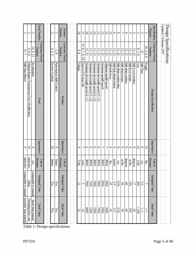
Table 1: Design specifications
P07310 Page 5 of 40
Driver pushes up/down shift button
Monitor RPMs for proper RPM range (based on current gear) and Reverse
Lockout button
Cut spark.Actuate shift.
Confirm Shift
Update current gear
Monitor load using throttle position and
RPMs
Throttle Position
Shift Actuators
RPM Sensor
Shift Drum Indicator
Up-Shift Button
Down-Shift Button
Ignition Attenuation
Gear Indicator Display
Reverse Lockout Button
Figure 1: System flow chart
P07310 Page 6 of 40

Design Specifications:
Critical Specifications: • The ESMT shall be safe to use. Aside from having a working system, this is the concern
identified as most important by our sponsor. This means that the ATV should never do something completely unexpected by the rider.
• The system shall utilize push buttons (or similar activation device) to control the shifting of the transmission. This semi-automatic system will serve as a proof of concept for the fully automated version.
Major Specifications: • System weight should be less than 7 lbs. One major complaint about the ATV that
preceded this model is that it was too heavy. The new model is about 30 lbs. lighter, and ideally, this system would not put much of that weight back on. For a vehicle that weighs less than 400 lbs. 7lbs. is much more significant than it would be on a larger vehicle.
• Clutch use shall not be required to use the system. Aside from gear selection, the shifting system shall require no other user inputs. While there are many potential solutions to this requirement, it is necessary to prove that rider inputs can effectively be eliminated from the shifting process.
• Reverse lockout should be retained or engineered. Currently, the reverse lockout system requires that the clutch be disengaged and a button be depressed before the ATV will shift into reverse. Either this system needs to be retained, or a suitable system needs to be integrated into the design solution. This is to ensure that in aggressive riding situations it is not possible to accidentally shift into reverse.
A complete list of specifications is found in Table 1. The customer needs assessment is found in Appendix A. Mechanical Controls Concept Development and Selection: Clutch Subsystem:
From the outset of the project, the major design choice regarding the clutch has been whether to automate the control or to create a system that does not require clutch actuation. Because of the design of the hydraulic clutch system, very few access points exist to actuate the clutch without disabling the manual lever. The functionality of the manual clutch lever was retained for many reasons. From a safety standpoint, it allows the rider more control for any situation in which full clutch control may be necessary. Additionally, in the event of a mechanical failure in which the ATV engine will not run, the manual clutch operation will allow the ATV to be pushed out of a hazardous situation. Additionally, this may be helpful in a garage situation where a mechanic is simply pushing the ATV around a workspace and does not need to start the engine.
P07310 Page 7 of 40

Figure 2: Clutch assembly drawing
When the clutch lever is pulled, the clutch slave cylinder pushes against the clutch rod (3). The clutch rod pushes against the pressure piece (1) which pushes against the pressure plate (9). This relieves pressure on the clutch disks (5, 6, 7) which are located between the pressure plate and the clutch hub (8).
Figure 3: Picture of assembled clutch Figure 4: Picture of semi-assembled clutch
P07310 Page 8 of 40
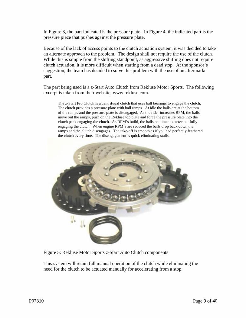
In Figure 3, the part indicated is the pressure plate. In Figure 4, the indicated part is the pressure piece that pushes against the pressure plate. Because of the lack of access points to the clutch actuation system, it was decided to take an alternate approach to the problem. The design shall not require the use of the clutch. While this is simple from the shifting standpoint, as aggressive shifting does not require clutch actuation, it is more difficult when starting from a dead stop. At the sponsor’s suggestion, the team has decided to solve this problem with the use of an aftermarket part. The part being used is a z-Start Auto Clutch from Rekluse Motor Sports. The following excerpt is taken from their website, www.rekluse.com.
The z-Start Pro Clutch is a centrifugal clutch that uses ball bearings to engage the clutch. The clutch provides a pressure plate with ball ramps. At idle the balls are at the bottom of the ramps and the pressure plate is disengaged. As the rider increases RPM, the balls move out the ramps, push on the Rekluse top plate and force the pressure plate into the clutch pack engaging the clutch. As RPM’s build, the balls continue to move out fully engaging the clutch. When engine RPM’s are reduced the balls drop back down the ramps and the clutch disengages. The take-off is smooth as if you had perfectly feathered the clutch every time. The disengagement is quick eliminating stalls.
Figure 5: Rekluse Motor Sports z-Start Auto Clutch components
This system will retain full manual operation of the clutch while eliminating the need for the clutch to be actuated manually for accelerating from a stop.
P07310 Page 9 of 40
Shift Actuation Subsystem: The shift actuation subsystem is the mechanical device(s) that physically shift the gears in the transmission. In generating concepts, many different mechanisms were introduced as possibilities. • Linear solenoids • Rotary solenoids • Stepper motors • Pneumatics • Hydraulics At this point, each of the mechanisms was evaluated for feasibility regarding our primary selection criteria: weight. In evaluating the potential weight of the systems and the design specification needed (7 lbs.) it was agreed that a pneumatic or hydraulic system was impractical for this application. The need for cylinders, reservoirs, or pumps increases the weight beyond acceptable terms. Additionally, assuming the weight could be kept to within specification, the relative benefits of such a system would be minimal with regards to the competing systems. The original concepts called for electromechanically actuating the foot shift lever. The required displacement for each gear shift at this location is 17o. Since the system ratchets with each gear change, the lever would return to a standard position after each shift. The required torque at this point is about 150 in-lbs. For this concept, rotary solenoids were first considered, however found to have insufficient torque for the application along with stepper motors. Concepts were generated using linear solenoids since the lever arm could be used to increase applied torque from the linear source. On that track, the following concepts were generated.
P07310 Page 10 of 40
Shift Actuation Concepts: Final Concept: Semi-Direct Shift Fork Actuation
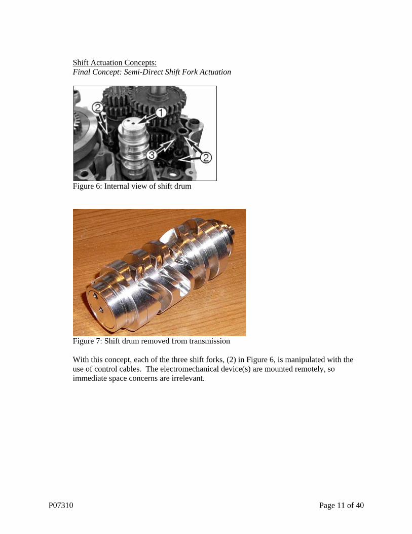
Figure 6: Internal view of shift drum
Figure 7: Shift drum removed from transmission With this concept, each of the three shift forks, (2) in Figure 6, is manipulated with the use of control cables. The electromechanical device(s) are mounted remotely, so immediate space concerns are irrelevant.
P07310 Page 11 of 40

Figure 8: Model of new shift drum
Figure 9: Shift fork In the model in Figure 8, the shift forks (Figure 9) will sit in the grooves cut in the side of the shift drum. The bushing indicated in Figure 9 will fit into a groove cut into the shift drum. Each groove allows for the needed axial displacement of each fork to occur. One groove is not visible from this angle. Each fork will have a control cable/rod attached. The cable will have a rigid rod at the end to avoid deflection as the control cable/rod system will operate in both push and pull modes. A 4-40 cap head screw with a hole drilled in it will be attached to the center “nub” of the shift fork. This will protrude into the center hollow of the new shift drum and allow the control rod to be attached.
P07310 Page 12 of 40
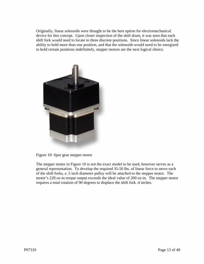
Originally, linear solenoids were thought to be the best option for electromechanical device for this concept. Upon closer inspection of the shift drum, it was seen that each shift fork would need to locate to three discrete positions. Since linear solenoids lack the ability to hold more than one position, and that the solenoids would need to be energized to hold certain positions indefinitely, stepper motors are the next logical choice.
Figure 10: Spur gear stepper motor The stepper motor in Figure 10 is not the exact model to be used, however serves as a general representation. To develop the required 35-50 lbs. of linear force to move each of the shift forks, a .5 inch diameter pulley will be attached to the stepper motor. The motor’s 228 oz-in torque output exceeds the ideal value of 200 oz-in. The stepper motor requires a total rotation of 90 degrees to displace the shift fork .4 inches.
P07310 Page 13 of 40

Figure 11: Stepper motor horn A set of three stepper motors will be required to move the shift forks, and thus packaging is something of a concern for the future. Since the motors can be remote mounted, this should not be a major concern. The weight of each motor is 1.6 lbs. giving a total motor weight of 4.8 lbs.
P07310 Page 14 of 40

Figure 12: Stepper motor/mounting assembly In Figure 12, the overall dimensions of the mounting bracket are 3” x 8”. The plates are 1/8” thick and the distance between the plates is equal to the length of the motor feature, 1.26”. Additionally, the model shows the motor output shafts cut to an overall length of .5”.
P07310 Page 15 of 40

Concept 1: One Push-Pull Solenoid
Figure 13: Concept utilizing push/pull linear solenoid Concept 2: Two Pull Solenoids
Figure 14: Concept utilizing two pull solenoids In each of the designs, the shift lever is actuated by the solenoid(s) connected via control lines. The shift lever changes the gears by moving upward or downward. The rotation is approximately 17 degrees in either direction and the action is ratcheted so that the shift lever always returns to the reference position shown.
Control line
Solenoid (remote mounted)
Shift drum
Shift lever
Solenoids (remote mounted) Control lines
Shift drum
Shift lever
P07310 Page 16 of 40

Upon further investigation, both concepts were found to be infeasible due to solenoid parameters. A long lever arm reduced the amount of linear force necessary, but increased the needed displacement. When suitable solenoids were found, they were either too heavy or consumed too much power (~1500W). With a transmission physically present (it had not yet arrived during the generation of the previous concepts) a new approach was investigated. Instead of actuating the shift lever, the shift drum would be actuated instead. The displacement requirement is greater, 60 degrees, but the torque requirement is much lower (~20-50 in.-lbs.). Concept 3: Direct Shift Drum Actuation
Figure 15: External view of shift drum The direct shift drum actuation concept planned to utilize a stepper motor or servo directly mated to the shift drum, (1) in Figure 6, via the existing holes for the pins (4) in Figure 15. The motor or servo would rotate to specific positions for each of the gears. This concept was eliminated due to extremely limited space in the proposed mounting area, and therefore an alternative concept was generated.
P07310 Page 17 of 40

Electrical System Concept: Programmable Logic Controller (PLC): A Transmission Control Unit (TCU) is a device that controls the transmission of the ATV. Using electrical sensors located on the ATV, gear shifting will be performed for optimal smoothness, efficiency, and performance. Data obtained from the sensors will be processed using a Programmable Logic Controller (PLC) to determine the ideal shifting times. Shifting will be controlled via pushbuttons. Each push of the button will result in a shift at a precise time, depending on the throttle position and RPM’s. When two immediate, consecutive shifts are entered, the shifts will be kept in a memory buffer and will be performed at the next opportunity. The Allen-Bradley 1760-L18DWD-EX Pico Controller PLC will be utilized in the control system design. This controller will be powered by a 12 Vdc input voltage and provide eight digital inputs and up to four analog inputs ranging from 0 to 10v. Six relay outputs are also included on the controller. This controller has enough memory for up to 512 instructions. All programming will be performed in C. See Figure 16 for flowchart overview of programming code. See Table 2 for a summary of specifications.
Specifications Memory Size 512 instructions Power Supply Input Voltage 10.2-15.6Vdc Input Voltage Range 8-15.6Vdc
Relay Output Current 8A resistive, 3A inductive
# of Analog Inputs 4 (0-10 Vdc) Digital Inputs 8 Outputs 6
Table 2: AB 1760-L18DWD-EX specifications
P07310 Page 18 of 40

Driver pushes up/down shift button
Monitor RPMs for proper RPM range (based on current gear) and Reverse
Lockout button
Cut spark.Actuate shift.
Confirm Shift
Update current gear
Monitor load using throttle position and
RPMs
Throttle Position
Shift Actuators
RPM Sensor
Shift Drum Indicator
Up-Shift Button
Down-Shift Button
Ignition Attenuation
Gear Indicator Display
Reverse Lockout Button
Figure 16: Flowchart overview of program Input/Output Summary: The throttle position sensor is used to monitor the position of the throttle in the engine. This is achieved by utilizing a potentiometer, providing a variable resistance based on the throttle position in a voltage divider. The potentiometer will be dived into eight sections: fully closed, fully opened, and six intermediate positions. Each section indicates a different range of the throttle position. By providing a variable resistance based on the throttle position, the voltage divider will give an output voltage corresponding to the throttle position region. This analog sensor can be found existing on the ATV in the carburetor and can be used, along with the RPM sensor, to determine the engine load. The RPM (revolutions per minute) sensor is used to monitor the RPM of the engine. This sensor is part of the ATV ignition control system. In the event that this sensor is not accessible on the ATV, an additional RPM sensor can be purchased with little extra effort. This sensor is an analog input into the PLC. When used in conjunction with the throttle position sensor, the engine and transmission load can be determined.
P07310 Page 19 of 40

The shift drum indicator sensor monitors the current gear of the transmission. This analog sensor monitors the rotation of the shift drum and indicates the current gear. This again can be found stock on the ATV. Because the mechanical design no longer rotates, this sensor will not be used. Instead, an output signal from the PLC will indicate the current gear to the gear indicator display. Shift buttons will be utilized for the rider to shift gear positions. Two buttons will be used, one to up-shift and one to downshift. Each button will provide a digital input using a normally closed (NC) switch. An NC switch allows current to flow at its rest state. When the switch is activated (button is pressed), current flow is prevented. The reverse lockout button will also utilize an NC switch and will operate similarly to the shift buttons. This button is needed because the original mechanical reverse lockout mechanism will not function with the non-rotating shift drum. The reverse lockout will be an electrical lockout that does not allow the rider to shift to neutral or reverse without this button being depressed. Additionally, certain state parameters must be met to allow the rider to shift to neutral or reverse, such as the ATV being fully stopped. This will prevent the rider from accidentally shifting to neutral or reverse in an aggressive riding situation. The shift actuator will be used to drive the stepper motors. There will be three stepper motors in total, each getting a separate input. This is needed since each of the shift forks will need to be in different positions at different times for each individual gear. The ignition attenuation will also be controlled. This output will cut the spark of the engine when activated. The precise system that will handle this will be controlled by the PLC. The spark attenuation will be controlled indirectly, via an external relay.
P07310 Page 20 of 40

Figure 17: Electrical control system schematic
P07310 Page 21 of 40

Control Interface and Gear Indicator Design: The goal of the Polaris ESMT team is to provide a push-button shifting system that is ergonomically sound, easily accessible to the rider, reliable in the most challenging environments and terrain. This system will be implemented on the Polaris Outlaw 525 high performance ATV. Figure 18 shows the front of the Polaris Outlaw 525 from the rider’s perspective. The left side of the handlebars has the start button, headlight controls and engine kill switch. There is also the gas tank located on the center, and the throttle mechanism on the right handle bar. The reverse lockout switch is also located to the right. The gear indicator screen is located on the center, forward of the handlebars from the rider’s perspective.
Gear Indicator Screen
Figure 18: Rider’s view on the Outlaw 525
Headlight Controls
Figure 19: Rider’s view of left hand controls
Engine Kill Switch
Start Press/Switch Button
The features of the start button, headlight controls, and kill switch were designed by Polaris Industries to satisfy the rider based on his seating and hand position. Figure 20 shows the location of the throttle mechanism box on the right side of the handle bar.
P07310 Page 22 of 40

Throttle Mechanism Box
Figure 20: Rider’s view of right hand controls The task analysis for making a new gear buttons is being required for the design of the gear button controls to have the following requirements: -
1. Location of the button controls – Left, Center or Right 2. Shape - minimal shape – square, rectangle, hexagonal, polygonal to meet the physical
condition of the driver. 3. Dimensions or Sizes 4. Environmental Conditions – Rain, Snow, Desert and others 5. Satisfaction 6. Quality Assurance
P07310 Page 23 of 40
Final Design: Push-button Interface
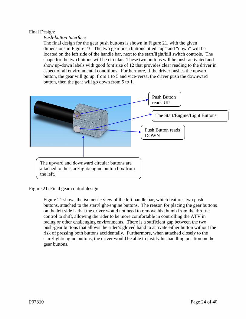
The final design for the gear push buttons is shown in Figure 21, with the given dimensions in Figure 23. The two gear push buttons titled “up” and “down” will be located on the left side of the handle bar, next to the start/light/kill switch controls. The shape for the two buttons will be circular. These two buttons will be push-activated and show up-down labels with good font size of 12 that provides clear reading to the driver in aspect of all environmental conditions. Furthermore, if the driver pushes the upward button, the gear will go up, from 1 to 5 and vice-versa, the driver push the downward button, then the gear will go down from 5 to 1.
Push Button reads UP
The upward and downward circular buttons are attached to the start/light/engine button box from the left.
Push Button reads DOWN
The Start/Engine/Light Buttons
Figure 21: Final gear control design
Figure 21 shows the isometric view of the left handle bar, which features two push buttons, attached to the start/light/engine buttons. The reason for placing the gear buttons on the left side is that the driver would not need to remove his thumb from the throttle control to shift, allowing the rider to be more comfortable in controlling the ATV in racing or other challenging environments. There is a sufficient gap between the two push-gear buttons that allows the rider’s gloved hand to activate either button without the risk of pressing both buttons accidentally. Furthermore, when attached closely to the start/light/engine buttons, the driver would be able to justify his handling position on the gear buttons.
P07310 Page 24 of 40
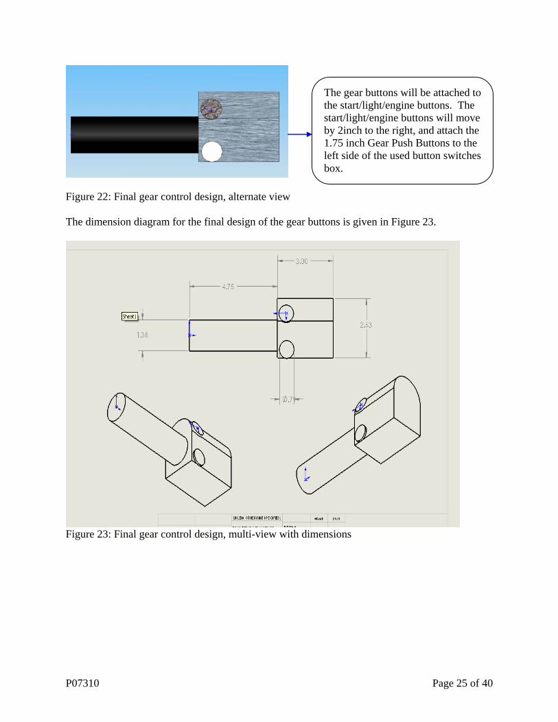
The gear buttons will be attached to the start/light/engine buttons. The start/light/engine buttons will move by 2inch to the right, and attach the 1.75 inch Gear Push Buttons to the left side of the used button switches box.
Figure 22: Final gear control design, alternate view The dimension diagram for the final design of the gear buttons is given in Figure 23.
Figure 23: Final gear control design, multi-view with dimensions
P07310 Page 25 of 40
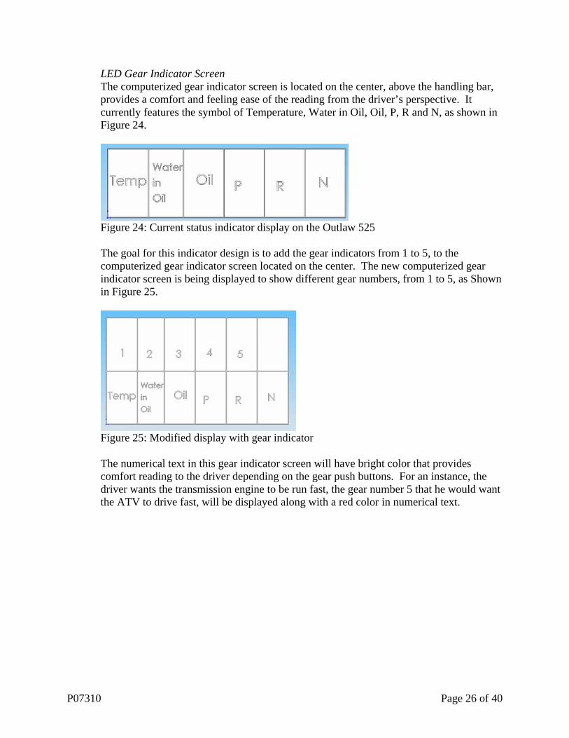
LED Gear Indicator Screen The computerized gear indicator screen is located on the center, above the handling bar, provides a comfort and feeling ease of the reading from the driver’s perspective. It currently features the symbol of Temperature, Water in Oil, Oil, P, R and N, as shown in Figure 24.
Figure 24: Current status indicator display on the Outlaw 525
The goal for this indicator design is to add the gear indicators from 1 to 5, to the computerized gear indicator screen located on the center. The new computerized gear indicator screen is being displayed to show different gear numbers, from 1 to 5, as Shown in Figure 25.
Figure 25: Modified display with gear indicator
The numerical text in this gear indicator screen will have bright color that provides comfort reading to the driver depending on the gear push buttons. For an instance, the driver wants the transmission engine to be run fast, the gear number 5 that he would want the ATV to drive fast, will be displayed along with a red color in numerical text.
P07310 Page 26 of 40
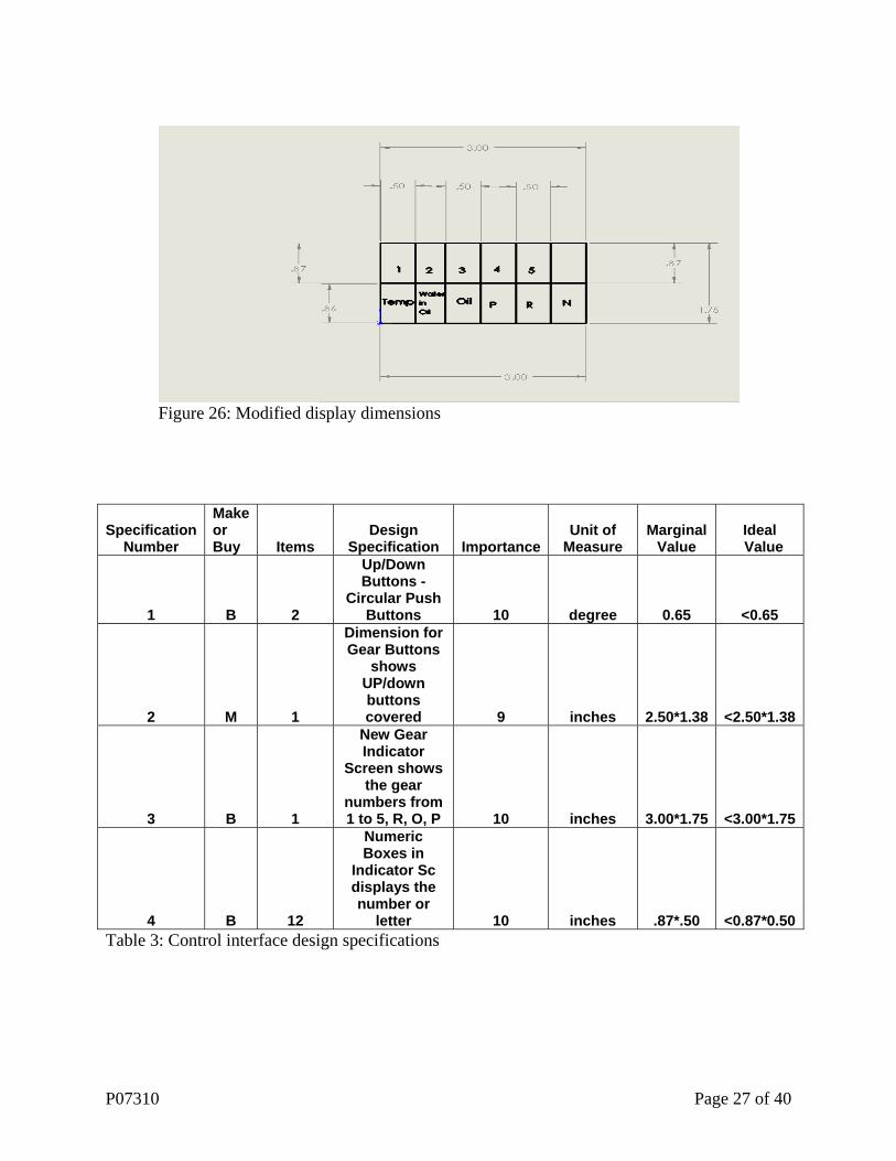
Figure 26: Modified display dimensions
Specification Number
Make or Buy Items
Design Specification Importance
Unit of Measure
Marginal Value
Ideal Value
1 B 2
Up/Down Buttons -
Circular Push Buttons 10 degree 0.65 <0.65
2 M 1
Dimension for Gear Buttons
shows UP/down buttons covered 9 inches 2.50*1.38 <2.50*1.38
3 B 1
New Gear Indicator
Screen shows the gear
numbers from 1 to 5, R, O, P 10 inches 3.00*1.75 <3.00*1.75
4 B 12
Numeric Boxes in
Indicator Sc displays the number or
letter 10 inches .87*.50 <0.87*0.50Table 3: Control interface design specifications
P07310 Page 27 of 40

Test Bed Design: The test bed for the transmission of the ATV will be designed and the purpose will be to simulate the loading of the transmission. The load on the transmission will vary with the weight of the rider as well as the operating conditions. Flywheels will be added to the output shaft to simulate the loading. This is a safer way instead of having an actual person ride the ATV.
Figure 27: Test bed layout Test Bed Base For the base of the test bed, a rectangular metal sheet (measuring 20” x 30”x 3/4”) will be used. The supports for the output shaft as well as a mount for the electric motor will be screwed to it. A mounting bracket for the ATV transmission will be screwed to it as well.
P07310 Page 28 of 40
Electric Motor/Motor Mount
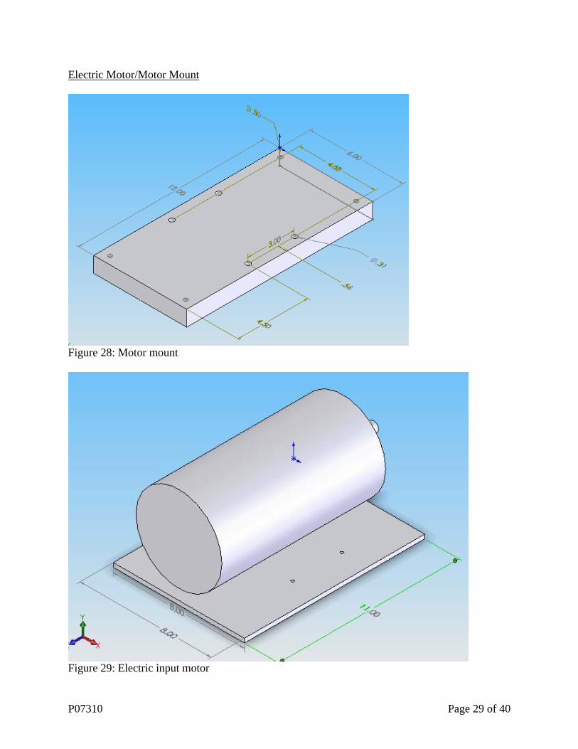
Figure 28: Motor mount
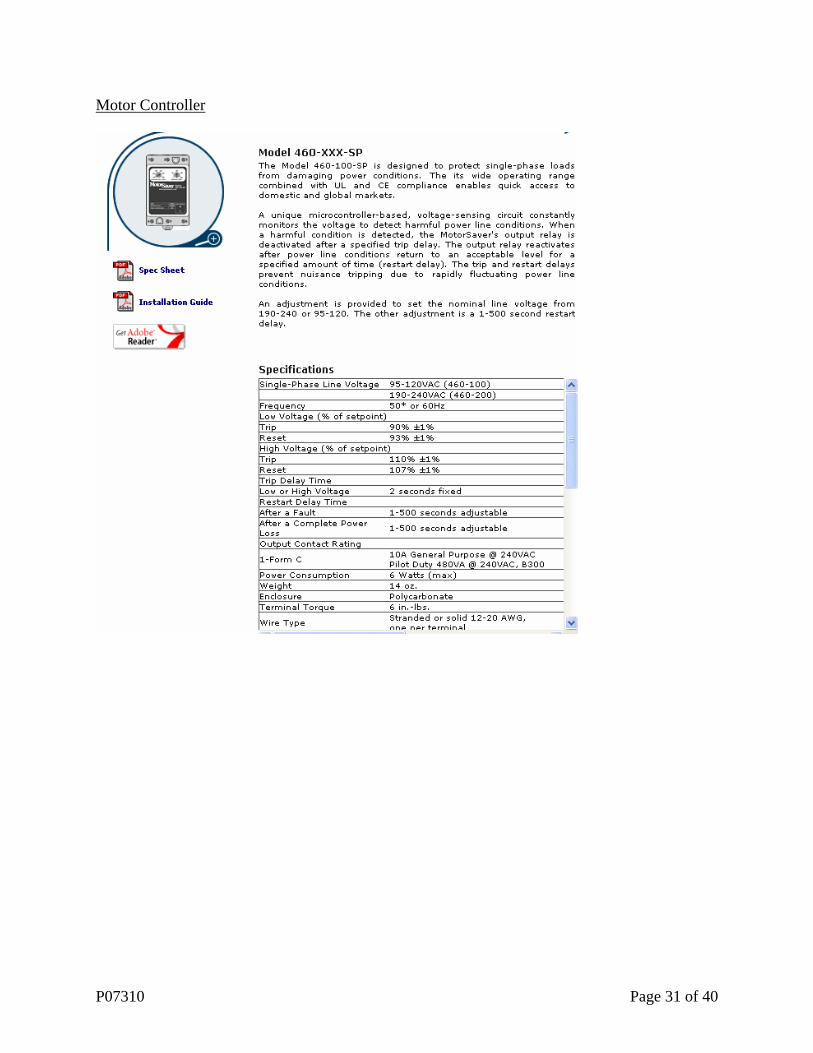
Figure 29: Electric input motor
P07310 Page 29 of 40

Table 4: Input motor dimensions
Motor Dimensions ValueOverall Length 11.8” Width (Between Holes) 4.88” Shaft Diameter 0.625” Ground to Shaft 3.5” Shaft Length 1.88” Base Hole Diameter 0.34” Distance Between Holes 3.00”
The electric motor will generate 3450 RPM and ¾ Horsepower. The test bed will be set up in the machine shop. The voltage and current for the motor will depend upon how much voltage the machine shop can provide coupled with the maximum allowable current to be used. After consulting with the machine shop, the available voltage is 220V single phase and the allowable current 20 Amps although 30 Amps is possible. At the moment, the voltage and current values that the room where the test bed will be set up is pending. The rotation will need to be clockwise since the input gear can only rotate in one direction.
Motor Properties ValueWeight 19 lbs HP ¾ RPM 3450 Volts 115/230 Enclosure Totally Enclosed Fan Cooled Type Capacitor Start Bearings Ball Rotation Reversible Base Welded base Full Load Amps @ N.P. Volts 9.8/4.9 Item AC Mtr. ¾ HP 3450 RPM 115/230 V FR
Capacitor Start, TEFC Table 5: Input motor specifications The distance between the ground and the input shaft is 4.5”. A mounting block 1” high will be used to compensate for this. The mounting block will be made from metal with a height of 1”, a width of 6” and a length of 12”. The there will be four threaded holes drilled in the middle of the block to mount the motor and 4 holes drilled on the ends of the block to mount on the test bed base.
P07310 Page 30 of 40
Motor Controller
P07310 Page 31 of 40
Input Shaft
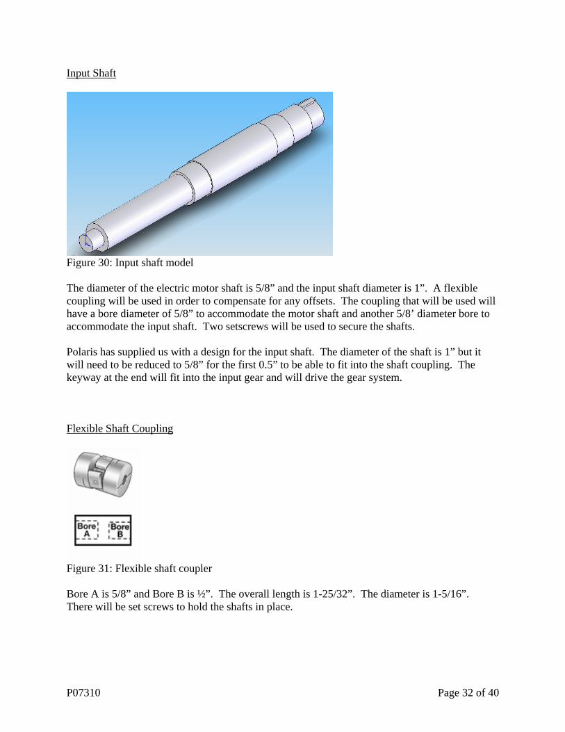
Figure 30: Input shaft model The diameter of the electric motor shaft is 5/8” and the input shaft diameter is 1”. A flexible coupling will be used in order to compensate for any offsets. The coupling that will be used will have a bore diameter of 5/8” to accommodate the motor shaft and another 5/8’ diameter bore to accommodate the input shaft. Two setscrews will be used to secure the shafts. Polaris has supplied us with a design for the input shaft. The diameter of the shaft is 1” but it will need to be reduced to 5/8” for the first 0.5” to be able to fit into the shaft coupling. The keyway at the end will fit into the input gear and will drive the gear system. Flexible Shaft Coupling
Figure 31: Flexible shaft coupler Bore A is 5/8” and Bore B is ½”. The overall length is 1-25/32”. The diameter is 1-5/16”. There will be set screws to hold the shafts in place.
P07310 Page 32 of 40

Gear Ratio The OD for the input gear is 2.75” while the OD for the clutch basket is 5.25”. The gear ratio is 0.524.
Figure 32: CAD image of gear to drive clutch basket
Figure 33: CAD image of clutch basket
P07310 Page 33 of 40

Figure 34: Input gear
Figure 35: Close up of clutch basket Mounting Brackets The mounting brackets will be made out of metal and the purpose of it will be to hold the transmission in place with no movement. The biggest challenge is to ensure that the transmission is firmly in place.
P07310 Page 34 of 40
Output Shaft
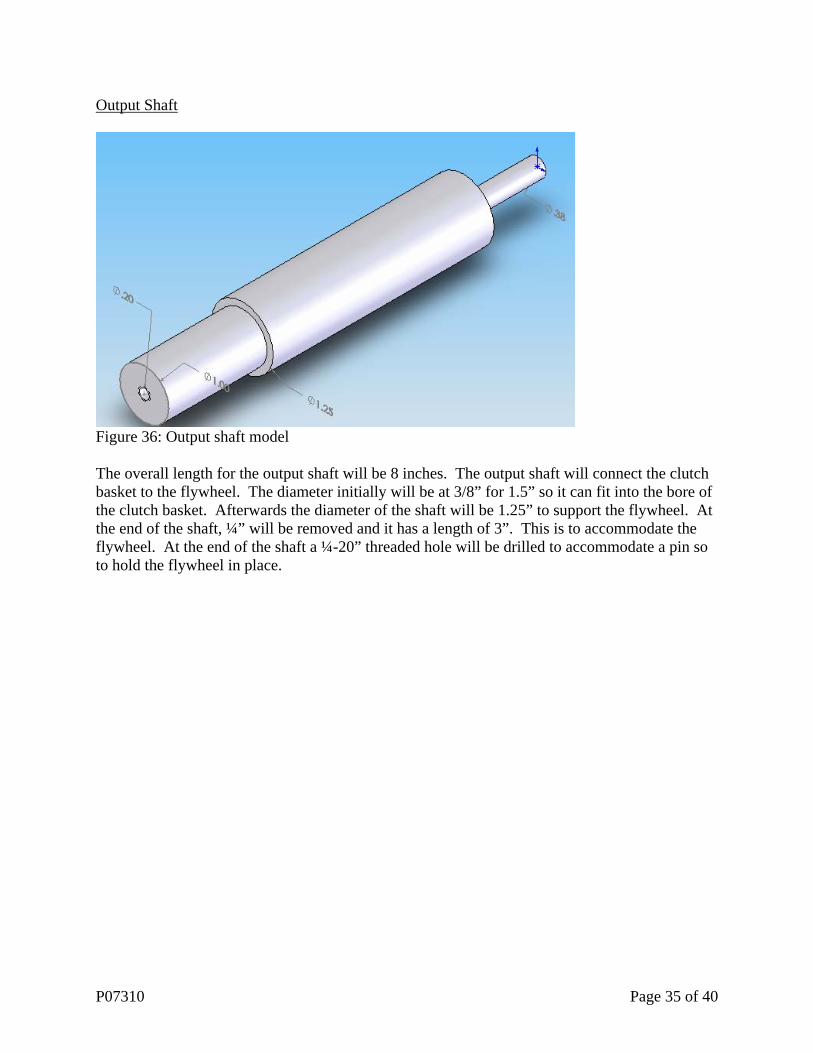
Figure 36: Output shaft model The overall length for the output shaft will be 8 inches. The output shaft will connect the clutch basket to the flywheel. The diameter initially will be at 3/8” for 1.5” so it can fit into the bore of the clutch basket. Afterwards the diameter of the shaft will be 1.25” to support the flywheel. At the end of the shaft, ¼” will be removed and it has a length of 3”. This is to accommodate the flywheel. At the end of the shaft a ¼-20” threaded hole will be drilled to accommodate a pin so to hold the flywheel in place.
P07310 Page 35 of 40
Shaft Mounts/Supports
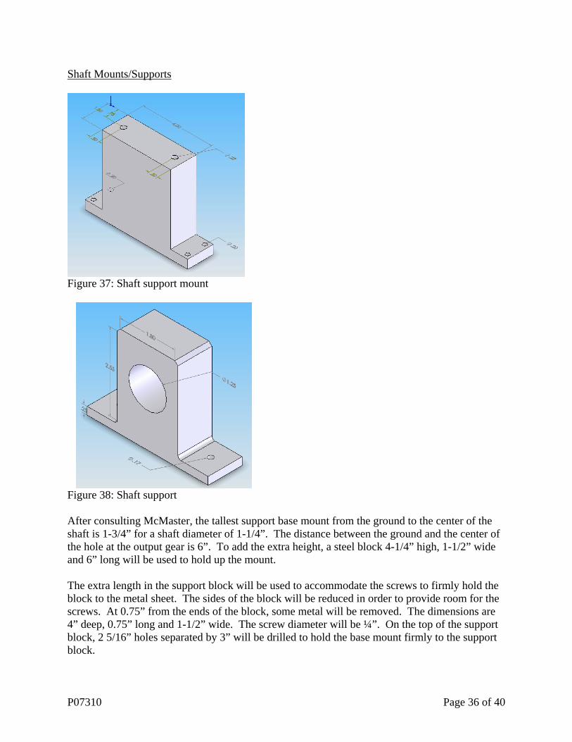
Figure 37: Shaft support mount
Figure 38: Shaft support After consulting McMaster, the tallest support base mount from the ground to the center of the shaft is 1-3/4” for a shaft diameter of 1-1/4”. The distance between the ground and the center of the hole at the output gear is 6”. To add the extra height, a steel block 4-1/4” high, 1-1/2” wide and 6” long will be used to hold up the mount. The extra length in the support block will be used to accommodate the screws to firmly hold the block to the metal sheet. The sides of the block will be reduced in order to provide room for the screws. At 0.75” from the ends of the block, some metal will be removed. The dimensions are 4” deep, 0.75” long and 1-1/2” wide. The screw diameter will be ¼”. On the top of the support block, 2 5/16” holes separated by 3” will be drilled to hold the base mount firmly to the support block.
P07310 Page 36 of 40

Shaft Mount Dimensions
Overall Width 4” Overall Height 3” Overall Depth 1-1/8” Base to Center 1-3/4” Distance between holes 3” Mounting Hole 0.34” Bolt Size 5/16” Table 6: Shaft mount dimensions Flywheel/Pin The flywheel is attached to the output shaft. Weights in the form of circular steel discs will be added to the shaft. The diameter of the weights cannot exceed 7 inches due to limited space. Each weight will have a thickness of 1/2”. A 1” hole will be drilled in the center of each disc so it can be added to the output shaft similar to weights being added to a bar. To ensure that the weights do not fall off a pin with an outer diameter of 1-1/4” with a threaded ¼” diameter to be screwed into the end of the output shaft.
Figure 39: Flywheel
Figure 40: Flywheel mount
P07310 Page 37 of 40

Calculations on Max Load on Output Shaft: Power = Voltage * Input Current Power of motor = 230 V * 4.9 = 1127W Power Output = ((2* pi * RPM) / 60)* Torque From McMaster:
Torque = (hp * 63,000) / (rpm) Torque = (0.75 * 63,000) / (3450) Torque = 13.7 in.-lbs Power Output = ((2* pi* 3450)/60) * 13.7 Power Output = 557 W Gear Ratio: Diameter of input shaft gear / Diameter of output shaft gear (d/D) Gear Ratio = 2.75 / 5.25 Gear Ratio = 0.524 d / D = RPM in/ RPM out (2.75 / 5.25) = 3450 / RPM out) RPM out = 6586 rpm Power Output= ((2*pi*RPM out)/60) * Torque) Torque of Output Shaft = 557 / ((2*pi*6586)/60) Torque of output shaft = 0.807 in-lbs 1.25” = 3.175cm or 0.03175m Velocity of output shaft = (pi* D (0.03175) * RPM out (6586)) / 60 Velocity of output shaft = 10.9m/s Force = Power Output/Velocity
P07310 Page 38 of 40

Force = 557/10.9 =51.1N 51.1/9.81 = 5.2 kg 5.2 kg = 11 lbs (Max Load)
P07310 Page 39 of 40

Appendix A Needs Assessment Updated 11 January 2007 The ESMT is safe *** (1) The ESMT is easy to use * (2) The ESMT is compact and ergonomically sound ** (3) The ESMT has built in safety features *** (4) The ESMT retains a reverse lockout feature The electronic-shifted, manual transmission (ESMT) is a valuable investment to Polaris ** (5) The ESMT is easy to manufacture ** (6) The ESMT is economically viable to manufacture and sell ** (7) The ESMT improves brand name recognition ** (8) The ESMT offers visible quality improvements from previous models *** (9) The ESMT will allow Polaris to utilize one power train for all ATV’s The ESMT system (less transmission) is lightweight (under 7 lbs.) (10) The ESMT offers performance benefits *** (11) The shifts are made smoothly ** (12) Acceleration from a dead stop is crisp and consistent ** (13) Shifts are made quickly The ESMT is durable and reliable *** (14) The ESMT is reliable under all weather conditions and in all-terrain ** (15) The ESMT lasts the lifetime of product (ATV) ** (16) The ESMT is comprised of quality materials
P07310 Page 40 of 40


![Microsoft PowerPoint - Colombia Phase One Pre-Launch Spanish.pptx [Read-Only]](https://img.pdfslide.net/doc/110x75/568bd94a1a28ab2034a681b8/microsoft-powerpoint-colombia-phase-one-pre-launch-spanishpptx-read-only.jpg)