Embed Size (px)
Citation preview
TotalCAD 2D-3D
Version 2
Getting Started Guide
Focus Multimedia Ltd.The Studios
Lea Hall Enterprise ParkWheelhouse Road
RugeleyStaffordshireWS15 1LH
Tel: (+44) (0)1889 570156 Fax: (+44) (0)1889 583571
www.focusmm.co.uk
The material presented in this publication is copyright-protected, © 2010 by Focus Multimedia, Ltd. and may not be reproduced in any form, by any method for any purpose without the prior written consent of Focus. Information in this document is subject to change without notice. It is against the law to copy the software, except in accordance with the terms of the licensing agreement.


Focus Multimedia License Agreement
This Licence Agreement sets out the terms and conditions relating to the purchase and use by you of the Focus Essential software (the Software) included in this package. Please do not load the Software onto your computer unless you accept these terms.
1. By accepting this agreement, you do not become the owner of the Software, but you do have the right to use the Soft ware in accordance with this agreement.
2. The Software must not be installed on more than one computer at any one time but it may be installed, on a temporary replacement or a subsequent computer, providing the Software is first removed from the original computer.
3. Unauthorised copying, lending or resale under any scheme is strictly prohibited.
4. You agree to use your best efforts to take all reasonable steps to protect the Software, from unauthorised use, illegal reproduction or illicit distribution.
5. Focus Multimedia warrants for a period of ninety days from the date of purchase of this Software that under normal use, the material of the CD-ROM will not prove defective and that the Software is properly recorded on the CD-ROM.
If during the ninety day period, a defect should appear, you may return the Software to Focus Multimedia for replacement without charge and this is your sole right with respect to such a defect.
6. Focus Multimedia warrants that the Software will carry out the functions described on the packaging. The Software has been designed for a wide variety of functions and uses and Focus Multimedia is not in a position to predetermine what you will try to do with it.
7. The sole liability of Focus Multimedia in respect of the Software is as set out in paragraphs 5 and 6, and Focus Multimedia will not be responsible for any direct, incidental or consequential damages, such as, but not limited to, loss of profits or contracts, suffered by the purchaser.
8. You agree that regardless of the form of any claim you may have, that Focus Multimedia’s liability for any damages to you or any other party shall not exceed the purchase price paid by the first purchaser of the Software.
9. This Licence Agreement is to be governed by and interpreted in accordance with, the Laws of England and Wales. Any terms or conditions of this Agreement found to be unenforceable will be deleted, but will not affect the remaining terms and conditions of this Agreement.
Important: To qualify for free technical support, please register your product at : www.focusmm.co.uk/register

Registration Registration and activation are automatic for electronic downloads.
For manual installation you can register online at www.focusmm.co.uk/register. If you do not have Internet access, please contact Focus to register. Becoming a TotalCAD registered user has many advantages, including technical support and program updates.
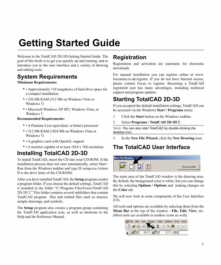
Starting TotalCAD 2D-3D If you accepted the default installation settings, TotalCAD can be accessed via the Windows Start / Programs menu.
1 Click the Start button on the Windows taskbar. 2 Select Programs / TotalCAD 2D-3D 2. NOTE: You can also start TotalCAD by double-clicking the desktop icon.
3 In the New File Wizard, click the New Drawing icon.
1
Getting Started Guide Welcome to the TotalCAD 2D-3D Getting Started Guide. The goal of this book is to get you quickly up and running, and to introduce you to the user interface and a variety of drawing and editing tools.
System Requirements Minimum Requirements:
• Approximately 110 megabytes of hard drive space for • a compact installation. • 256 Mb RAM (512 Mb on Windows Vista or • Windows 7) • Microsoft Windows XP SP2, Windows Vista, or • Windows 7.
Recommended Requirements:
• A Pentium 4 (or equivalent, or better) processor • • 512 Mb RAM (1024 Mb on Windows Vista or • Windows 7) • A graphics card with OpenGL support• • A monitor capable of at least 1024 x 768 resolution •
Installing TotalCAD 2D-3D To install TotalCAD, insert the CD into your CD-ROM. If the installation process does not start automatically, select Start / Run from the Windows taskbar and type D:\setup.exe (where D is the drive letter of the CD-ROM).
After you have installed TotalCAD, the Setup program creates a program folder. If you choose the default settings, TotalCAD is installed in the folder “C:\Program Files\Focus\TotalCAD 2D-3D 2.” This folder contains several subfolders that contain TotalCAD program files and related files such as macros, sample drawings, and symbols.
The Setup program also creates a program group containing the TotalCAD application icon, as well as shortcuts to the Help and the Reference Manual.
The TotalCAD User Interface
The main area of the TotalCAD window is the drawing area. By default, the background color is white, but you can change this by selecting Options / Options and making changes on the Color tab.
We will now look at some components of the User Interface (UI).
All tools and options are available by selecting them from the Menu Bar at the top of the window - File, Edit, View, etc. (Most tools are available in toolbox icons as well).
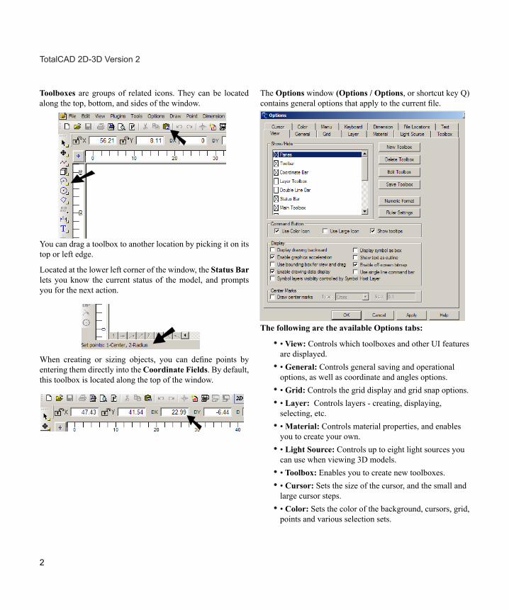
The Options window (Options / Options, or shortcut key Q) contains general options that apply to the current file.
The following are the available Options tabs:
•• View: Controls which toolboxes and other UI features are displayed. •• General: Controls general saving and operational options, as well as coordinate and angles options. •• Grid: Controls the grid display and grid snap options. •• Layer: Controls layers - creating, displaying, selecting, etc. •• Material: Controls material properties, and enables you to create your own. •• Light Source: Controls up to eight light sources you can use when viewing 3D models. •• Toolbox: Enables you to create new toolboxes. •• Cursor: Sets the size of the cursor, and the small and large cursor steps. •• Color: Sets the color of the background, cursors, grid, points and various selection sets.
Toolboxes are groups of related icons. They can be located along the top, bottom, and sides of the window.
You can drag a toolbox to another location by picking it on its top or left edge.
Located at the lower left corner of the window, the Status Bar lets you know the current status of the model, and prompts you for the next action.
When creating or sizing objects, you can define points by entering them directly into the Coordinate Fields. By default, this toolbox is located along the top of the window.
2
TotalCAD 2D-3D Version 2
Currently this file has no units, as you can see by the term “Unitless” listed in the Status Bar, along the bottom of the window.
•• Menu: Sets how commands appear on the main menu, and enables you to add custom commands to any menu. •• Keyboard: Enables you to create or change shortcut keys. •• Dimension: Controls dimension commands, including the Pullout and Balloon tools. •• File locations: Controls where TotalCAD stores the various files it uses and produces.
• Text: Controls color and style for text and attributes.
Drawing Line Objects In the blank file, we’ll start by displaying the grid. 1. From the scrollbar along the right side of the window, click Display Grid.
The grid appears, with lines every 5 units. (You can change grid spacing and colors by selecting Option / Option / Grid tab.)
2. Click on “Unitless” and select Change Units.
3. Select Centimeters and click OK.
Now “cm” is listed in the Status Bar, and the units displayed in the rulers are listed in cm.
4. The first tool we will use is Line. From the Main Toolbox (along the left side), click the Line icon.
3
Getting Started Guide
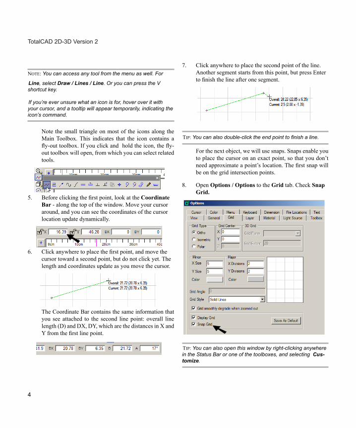
7. Click anywhere to place the second point of the line. Another segment starts from this point, but press Enter to finish the line after one segment.
TIP: You can also double-click the end point to finish a line.
For the next object, we will use snaps. Snaps enable you to place the cursor on an exact point, so that you don’t need approximate a point’s location. The first snap will be on the grid intersection points.
8. Open Options / Options to the Grid tab. Check Snap Grid.
TIP: You can also open this window by right-clicking anywhere in the Status Bar or one of the toolboxes, and selecting Cus-tomize.
NOTE: You can access any tool from the menu as well. For
Line, select Draw / Lines / Line. Or you can press the V shortcut key.
If you’re ever unsure what an icon is for, hover over it with your cursor, and a tooltip will appear temporarily, indicating the icon’s command.
Note the small triangle on most of the icons along the Main Toolbox. This indicates that the icon contains a fly-out toolbox. If you click and hold the icon, the fly-out toolbox will open, from which you can select related tools.
5. Before clicking the first point, look at the Coordinate Bar - along the top of the window. Move your cursor around, and you can see the coordinates of the cursor location update dynamically.
6. Click anywhere to place the first point, and move the cursor toward a second point, but do not click yet. The length and coordinates update as you move the cursor.
The Coordinate Bar contains the same information that you see attached to the second line point: overall line length (D) and DX, DY, which are the distances in X and Y from the first line point.
4
TotalCAD 2D-3D Version 2
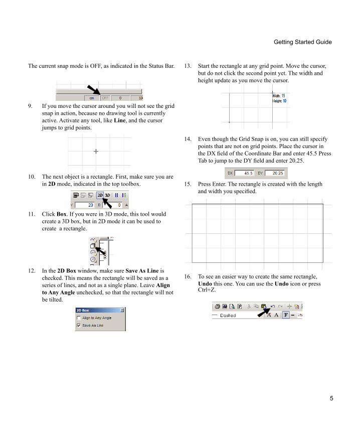
13. Start the rectangle at any grid point. Move the cursor, but do not click the second point yet. The width and height update as you move the cursor.
The current snap mode is OFF, as indicated in the Status Bar.
9. If you move the cursor around you will not see the grid snap in action, because no drawing tool is currently active. Activate any tool, like Line, and the cursor jumps to grid points.
10. The next object is a rectangle. First, make sure you are in 2D mode, indicated in the top toolbox.
11. Click Box. If you were in 3D mode, this tool would create a 3D box, but in 2D mode it can be used to create a rectangle.
12. In the 2D Box window, make sure Save As Line is checked. This means the rectangle will be saved as a series of lines, and not as a single plane. Leave Align to Any Angle unchecked, so that the rectangle will not be tilted.
14. Even though the Grid Snap is on, you can still specify points that are not on grid points. Place the cursor in the DX field of the Coordinate Bar and enter 45.5 Press Tab to jump to the DY field and enter 20.25.
15. Press Enter. The rectangle is created with the length and width you specified.
16. To see an easier way to create the same rectangle, Undo this one. You can use the Undo icon or press Ctrl+Z.
5
Getting Started Guide
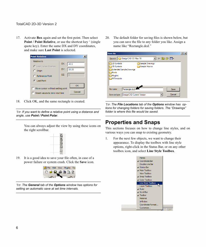
17. Activate Box again and set the first point. Then select Point / Point Relative, or use the shortcut key ‘ (single quote key). Enter the same DX and DY coordinates, and make sure Last Point is selected.
18. Click OK, and the same rectangle is created.
TIP: If you want to define a relative point using a distance and angle, use Point / Point Polar.
You can always adjust the view by using these icons on the right scrollbar.
19. It is a good idea to save your file often, in case of a power failure or system crash. Click the Save icon.
TIP: The General tab of the Options window has options for setting an automatic save at set time intervals.
20. The default folder for saving files is shown below, but you can save the file to any folder you like. Assign a name like “Rectangle.dcd.”
TIP: The File Locations tab of the Options window has op-tions for changing folders for saving folders. The “Drawings” folder is where this file would be saved.
Properties and Snaps This sections focuses on how to change line styles, and on various ways you can snap to existing geometry.
1. For the next few objects, we want to change their appearance. To display the toolbox with line style options, right-click in the Status Bar, or on any other toolbox icon, and select Line Style Toolbox.
6
TotalCAD 2D-3D Version 2
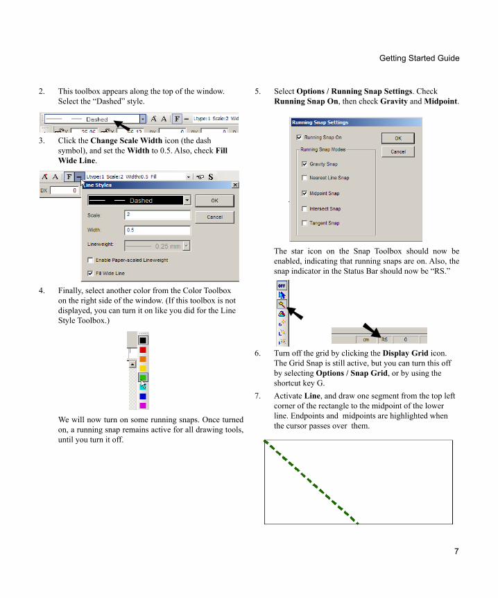
5. Select Options / Running Snap Settings. Check Running Snap On, then check Gravity and Midpoint.
2. This toolbox appears along the top of the window. Select the “Dashed” style.
3. Click the Change Scale Width icon (the dash symbol), and set the Width to 0.5. Also, check Fill Wide Line.
4. Finally, select another color from the Color Toolbox on the right side of the window. (If this toolbox is not displayed, you can turn it on like you did for the Line Style Toolbox.)
We will now turn on some running snaps. Once turned on, a running snap remains active for all drawing tools, until you turn it off.
The star icon on the Snap Toolbox should now be enabled, indicating that running snaps are on. Also, the snap indicator in the Status Bar should now be “RS.”
6. Turn off the grid by clicking the Display Grid icon. The Grid Snap is still active, but you can turn this off by selecting Options / Snap Grid, or by using the shortcut key G.
7. Activate Line, and draw one segment from the top left corner of the rectangle to the midpoint of the lower line. Endpoints and midpoints are highlighted when the cursor passes over them.
7
Getting Started Guide
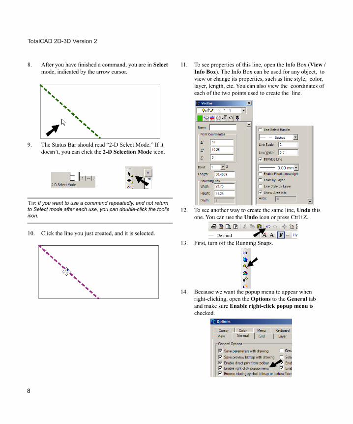
8. After you have finished a command, you are in Select mode, indicated by the arrow cursor.
9. The Status Bar should read “2-D Select Mode.” If it doesn’t, you can click the 2-D Selection Mode icon.
TIP: If you want to use a command repeatedly, and not return to Select mode after each use, you can double-click the tool’s icon.
10. Click the line you just created, and it is selected.
11. To see properties of this line, open the Info Box (View / Info Box). The Info Box can be used for any object, to view or change its properties, such as line style, color, layer, length, etc. You can also view the coordinates of each of the two points used to create the line.
12. To see another way to create the same line, Undo this one. You can use the Undo icon or press Ctrl+Z.
13. First, turn off the Running Snaps.
14. Because we want the popup menu to appear when right-clicking, open the Options to the General tab and make sure Enable right-click popup menu is checked.
8
TotalCAD 2D-3D Version 2
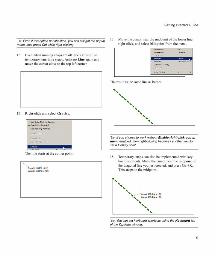
17. Move the cursor near the midpoint of the lower line, right-click, and select Midpoint from the menu.
The result is the same line as before.
TIP: If you choose to work without Enable right-click popup menu enabled, then right-clicking becomes another way to set a Gravity point.
18. Temporary snaps can also be implemented with key-board shortcuts. Move the cursor near the midpoint of the diagonal line you just created, and press Ctrl+K. This snaps to the midpoint.
TIP: You can set keyboard shortcuts using the Keyboard tab of the Options window.
Getting Started Guide
TIP: Even if this option not checked, you can still get the popup menu. Just press Ctrl while right-clicking.
15. Even when running snaps are off, you can still use temporary, one-time snaps. Activate Line again and move the cursor close to the top left corner.
16. Right-click and select Gravity.
The line starts at the corner point.
9
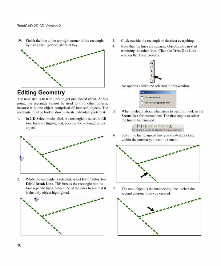
19. Finish the line at the top right corner of the rectangle by using the . (period) shortcut key.
Editing Geometry The next step is to trim lines to get one closed chain. At this point, the rectangle cannot be used to trim other objects, because it is one object comprised of four sub-objects. The rectangle must be broken down into its individual parts first.
1. In 2-D Select mode, click the rectangle to select it. All four lines are highlighted, because the rectangle is one object.
2. While the rectangle is selected, select Edit / Selection Edit / Break Line. This breaks the rectangle into its four separate lines. Select one of the lines to see that it is the only object highlighted.
3. Click outside the rectangle to deselect everything. 4. Now that the lines are separate objects, we can start
trimming the other lines. Click the Trim One Line icon on the Main Toolbox.
No options need to be selected in this window.
5. When in doubt about what steps to perform, look in the Status Bar for instructions. The first step is to select the line to be trimmed.
6. Select the first diagonal line you created, clicking within the portion you want to remain.
7. The next object is the intersecting line - select the second diagonal line you created.
10
TotalCAD 2D-3D Version 2
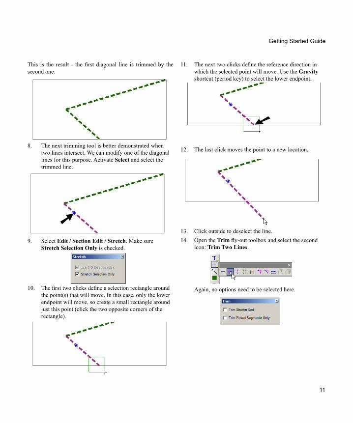
11. The next two clicks define the reference direction in which the selected point will move. Use the Gravity shortcut (period key) to select the lower endpoint.
12. The last click moves the point to a new location.
13. Click outside to deselect the line. 14. Open the Trim fly-out toolbox and select the second
icon: Trim Two Lines.
Again, no options need to be selected here.
Getting Started Guide
This is the result - the first diagonal line is trimmed by the second one.
8. The next trimming tool is better demonstrated when two lines intersect. We can modify one of the diagonal lines for this purpose. Activate Select and select the trimmed line.
9. Select Edit / Section Edit / Stretch. Make sure Stretch Selection Only is checked.
10. The first two clicks define a selection rectangle around the point(s) that will move. In this case, only the lower endpoint will move, so create a small rectangle around just this point (click the two opposite corners of the rectangle).
11
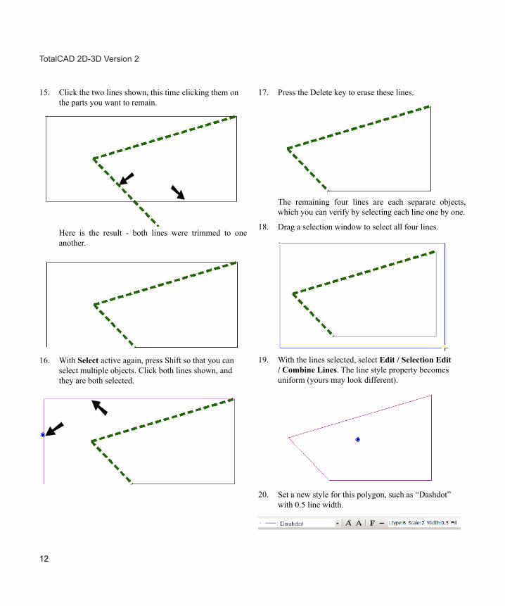
15. Click the two lines shown, this time clicking them on the parts you want to remain.
Here is the result - both lines were trimmed to one another.
16. With Select active again, press Shift so that you can select multiple objects. Click both lines shown, and they are both selected.
17. Press the Delete key to erase these lines.
The remaining four lines are each separate objects, which you can verify by selecting each line one by one.
18. Drag a selection window to select all four lines.
19. With the lines selected, select Edit / Selection Edit / Combine Lines. The line style property becomes uniform (yours may look different).
20. Set a new style for this polygon, such as “Dashdot” with 0.5 line width.
12
TotalCAD 2D-3D Version 2
Getting Started Guide
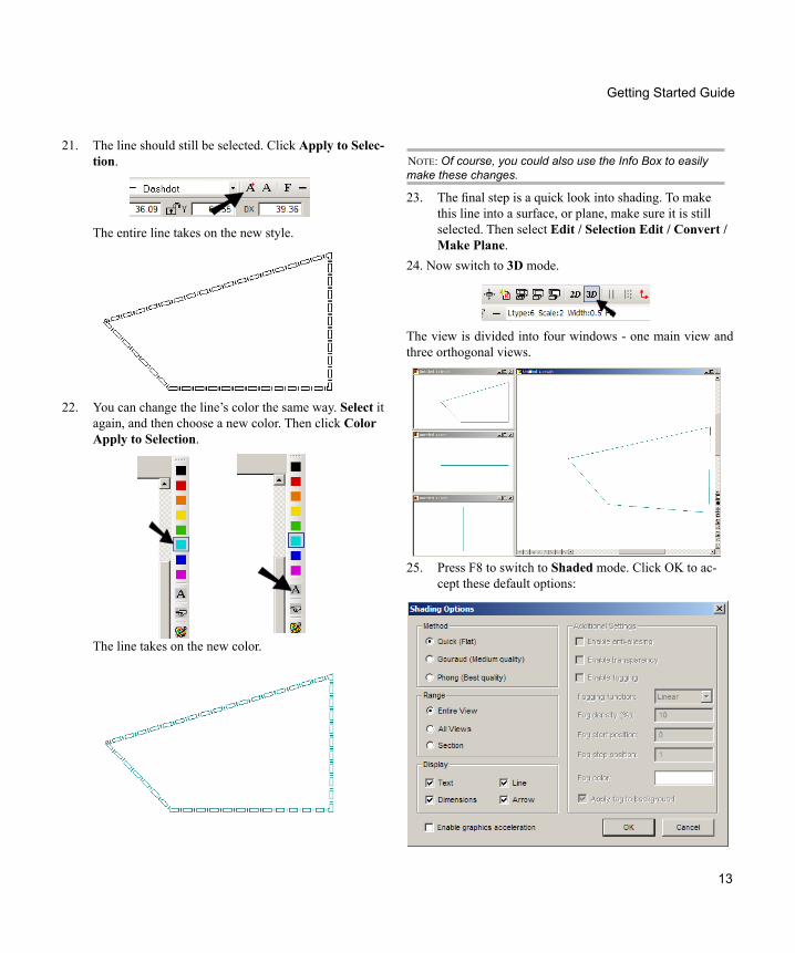
21. The line should still be selected. Click Apply to Selec-tion.
The entire line takes on the new style.
22. You can change the line’s color the same way. Select it again, and then choose a new color. Then click Color Apply to Selection.
The line takes on the new color.
NOTE: Of course, you could also use the Info Box to easily make these changes.
23. The final step is a quick look into shading. To make this line into a surface, or plane, make sure it is still selected. Then select Edit / Selection Edit / Convert / Make Plane.
24. Now switch to 3D mode.
The view is divided into four windows - one main view and three orthogonal views.
25. Press F8 to switch to Shaded mode. Click OK to ac-cept these default options:
13

In the main view, the plane is filled in.
Arcs and Circles In this section, you will create a plane consisting of lines, arcs, and circles.
1. Start a new file. You can press Ctrl+N or select File / New. Units in this file are not important.
2. Work in 2-D mode. Activate Line and click the start point.
3. Before defining the second point, click the horizon-tal arrow at the lower left corner of the window. This restricts the current object to be horizontal.
4. Click the endpoint to create a horizontal line.
5. Attached to this line will be a semi-circle. Open the Arc fly-out toolbox and click the Semi-Circle icon.
TIP: Arc tools can also be found in the Draw / Arcs menu.
6. Leave Draw as a Line unchecked. If this option is used, the arc is approximated as a series of small line segments.
7. Use a Gravity snap (either running or temporary) to start the arc at the endpoint of the line.
8. For the next endpoint, click the vertical arrow.
9. Place the next endpoint to create the semi-circle.
10. These two objects will be copied to complete the closed shape. First, select the line.
14
TotalCAD 2D-3D Version 2
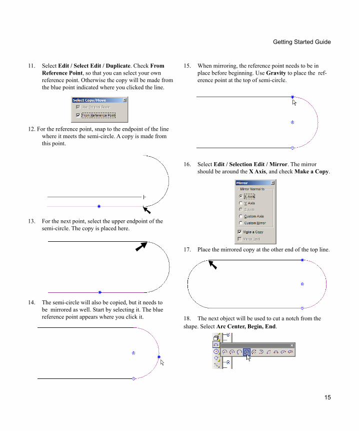
15. When mirroring, the reference point needs to be in place before beginning. Use Gravity to place the ref-erence point at the top of semi-circle.
16. Select Edit / Selection Edit / Mirror. The mirror should be around the X Axis, and check Make a Copy.
17. Place the mirrored copy at the other end of the top line.
18. The next object will be used to cut a notch from the shape. Select Arc Center, Begin, End.
Getting Started Guide
11. Select Edit / Select Edit / Duplicate. Check From Reference Point, so that you can select your own reference point. Otherwise the copy will be made from the blue point indicated where you clicked the line.
12. For the reference point, snap to the endpoint of the line where it meets the semi-circle. A copy is made from this point.
13. For the next point, select the upper endpoint of the semi-circle. The copy is placed here.
14. The semi-circle will also be copied, but it needs to be mirrored as well. Start by selecting it. The blue reference point appears where you click it.
15
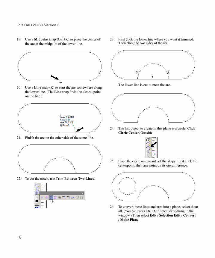
19. Use a Midpoint snap (Ctrl+K) to place the center of the arc at the midpoint of the lower line.
20. Use a Line snap (K) to start the arc somewhere along the lower line. (The Line snap finds the closest point on the line.)
21. Finish the arc on the other side of the same line.
22. To cut the notch, use Trim Between Two Lines.
23. First click the lower line where you want it trimmed. Then click the two sides of the arc.
The lower line is cut to meet the arc.
24. The last object to create in this plane is a circle. Click Circle Center, Outside.
25. Place the circle on one side of the shape. First click the centerpoint, then any point on its circumference.
26. To convert these lines and arcs into a plane, select them all. (You can press Ctrl+A to select everything in the window.) Then select Edit / Selection Edit / Convert / Make Plane.
16
TotalCAD 2D-3D Version 2
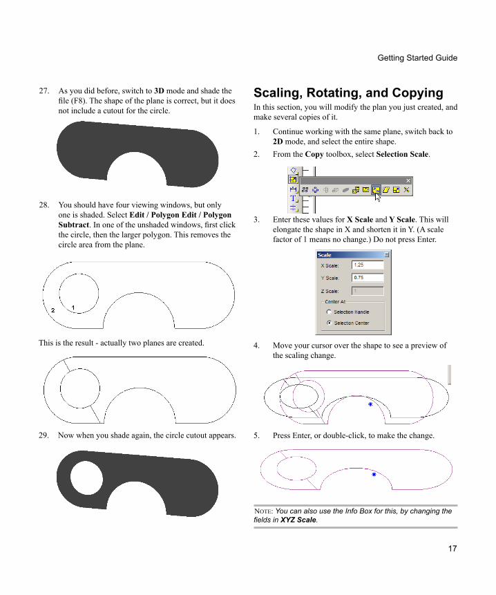
Scaling, Rotating, and Copying In this section, you will modify the plan you just created, and make several copies of it.
1. Continue working with the same plane, switch back to 2D mode, and select the entire shape.
2. From the Copy toolbox, select Selection Scale.
3. Enter these values for X Scale and Y Scale. This will elongate the shape in X and shorten it in Y. (A scale factor of 1 means no change.) Do not press Enter.
4. Move your cursor over the shape to see a preview of the scaling change.
5. Press Enter, or double-click, to make the change.
NOTE: You can also use the Info Box for this, by changing the fields in XYZ Scale.
This is the result - actually two planes are created.
Getting Started Guide
27. As you did before, switch to 3D mode and shade the file (F8). The shape of the plane is correct, but it does not include a cutout for the circle.
28. You should have four viewing windows, but only one is shaded. Select Edit / Polygon Edit / Polygon Subtract. In one of the unshaded windows, first click the circle, then the larger polygon. This removes the circle area from the plane.
29. Now when you shade again, the circle cutout appears.
17
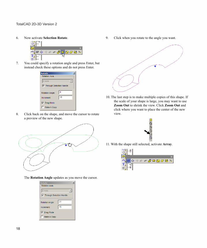
6. Now activate Selection Rotate.
7. You could specify a rotation angle and press Enter, but instead check these options and do not press Enter.
8. Click back on the shape, and move the cursor to rotate a preview of the new shape.
The Rotation Angle updates as you move the cursor.
9. Click when you rotate to the angle you want.
10. The last step is to make multiple copies of this shape. If the scale of your shape is large, you may want to use Zoom Out to shrink the view. Click Zoom Out and click where you want to place the center of the new view.
11. With the shape still selected, activate Array.
18
TotalCAD 2D-3D Version 2
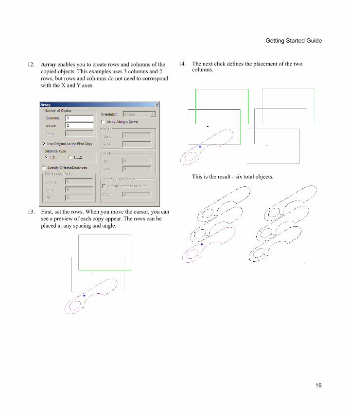
14. The next click defines the placement of the two columns.
12. Array enables you to create rows and columns of the copied objects. This examples uses 3 columns and 2 rows, but rows and columns do not need to correspond with the X and Y axes.
13. First, set the rows. When you move the cursor, you can see a preview of each copy appear. The rows can be placed at any spacing and angle.
This is the result - six total objects.
19
Getting Started Guide
6. Use Gravity snaps to create the curve along the series of pointmarks.
When finished, the curve should run smoothly through each pointmark. Press Enter to finish the curve.
TIP: While creating the curve, you can undo segments one step at a time by using the Esc key.
7. Undo this curve, and activate Bezier Curve.
8. This curve does not run through all selected point-marks. Rather, each point works as a guideline for setting the curve tangency.
Points and Curves In this section, you will play with a few different types of curves.
1. Start another file, or pan to some blank space in the current file. (You can pan by dragging the scroll bars up or down, or side to side.)
2. Open the Line toolbox to the Pointmark tool.
3. There are several options for the pointmarks’ appear-ance. This example uses Circle.
4. Create several pointmarks like this:
5. The first object to try is Curve, located in the same toolbox.
20
TotalCAD 2D-3D Version 2
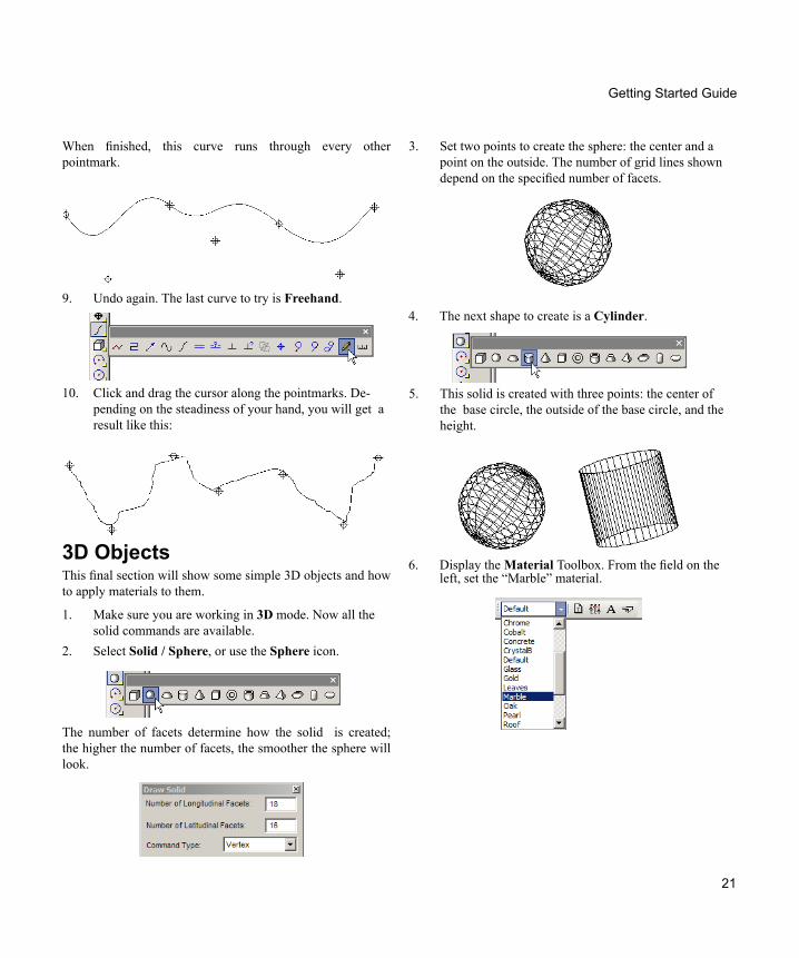
When finished, this curve runs through every other pointmark.
9. Undo again. The last curve to try is Freehand.
10. Click and drag the cursor along the pointmarks. De-pending on the steadiness of your hand, you will get a result like this:
3D Objects This final section will show some simple 3D objects and how to apply materials to them.
1. Make sure you are working in 3D mode. Now all the solid commands are available.
2. Select Solid / Sphere, or use the Sphere icon.
The number of facets determine how the solid is created; the higher the number of facets, the smoother the sphere will look.
3. Set two points to create the sphere: the center and a point on the outside. The number of grid lines shown depend on the specified number of facets.
4. The next shape to create is a Cylinder.
5. This solid is created with three points: the center of the base circle, the outside of the base circle, and the height.
6. Display the Material Toolbox. From the field on the left, set the “Marble” material.
21
Getting Started Guide
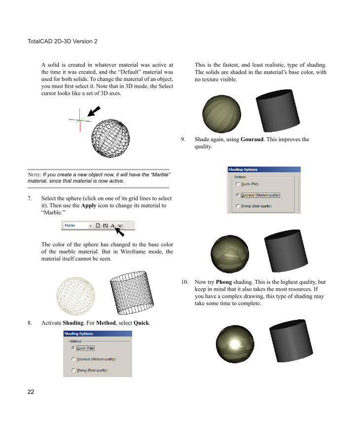
8. Activate Shading. For Method, select Quick.
A solid is created in whatever material was active at the time it was created, and the “Default” material was used for both solids. To change the material of an object, you must first select it. Note that in 3D mode, the Select cursor looks like a set of 3D axes.
NOTE: If you create a new object now, it will have the “Marble” material, since that material is now active.
7. Select the sphere (click on one of its grid lines to select it). Then use the Apply icon to change its material to “Marble.”
The color of the sphere has changed to the base color of the marble material. But in Wireframe mode, the material itself cannot be seen.
This is the fastest, and least realistic, type of shading. The solids are shaded in the material’s base color, with no texture visible.
9. Shade again, using Gouraud. This improves the quality.
10. Now try Phong shading. This is the highest quality, but keep in mind that it also takes the most resources. If you have a complex drawing, this type of shading may take some time to complete.
22
TotalCAD 2D-3D Version 2
Getting Started Guide
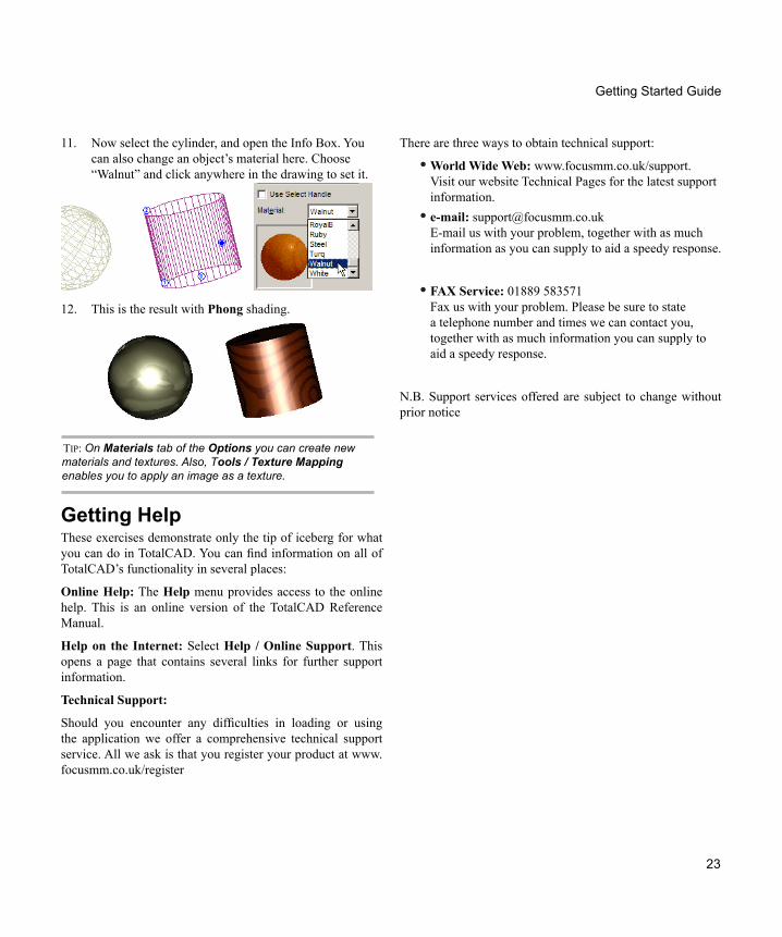
11. Now select the cylinder, and open the Info Box. You can also change an object’s material here. Choose “Walnut” and click anywhere in the drawing to set it.
12. This is the result with Phong shading.
TIP: On Materials tab of the Options you can create new materials and textures. Also, Tools / Texture Mapping enables you to apply an image as a texture.
Getting Help These exercises demonstrate only the tip of iceberg for what you can do in TotalCAD. You can find information on all of TotalCAD’s functionality in several places:
Online Help: The Help menu provides access to the online help. This is an online version of the TotalCAD Reference Manual.
Help on the Internet: Select Help / Online Support. This opens a page that contains several links for further support information.
Technical Support:
Should you encounter any difficulties in loading or using the application we offer a comprehensive technical support service. All we ask is that you register your product at www.focusmm.co.uk/register
23
There are three ways to obtain technical support:
World Wide Web:• www.focusmm.co.uk/support. Visit our website Technical Pages for the latest support information.e-mail:• [email protected] E-mail us with your problem, together with as much information as you can supply to aid a speedy response.
FAX Service:• 01889 583571 Fax us with your problem. Please be sure to state a telephone number and times we can contact you, together with as much information you can supply to aid a speedy response.
N.B. Support services offered are subject to change without prior notice

24
TotalCAD 2D-3D Version 2


![Skaffold - storage.googleapis.com · [getting-started getting-started] Hello world! [getting-started getting-started] Hello world! [getting-started getting-started] Hello world! 5](https://img.pdfslide.net/doc/110x75/5ec939f2a76a033f091c5ac7/skaffold-getting-started-getting-started-hello-world-getting-started-getting-started.jpg)