Embed Size (px)
Citation preview

July 2008City of Portland
offiCe of transPortation
Final Draft
designing for Truck MoveMenTs
and oTherLarge vehicLes
in PorTLand

Printed on Recycled Paper 6/08
Acknowledgements
City of Portland Office of TransportationSam Adams, Commissioner
Sue Keil, Director, Office of TransportationPaul Smith, Transportation Planning Division Manager
Office of Transportation Project StaffRobert Hillier, Freight Planning Coordinator/Project Manager
John Gillam, Policy Section ManagerDoug McCollum, Senior Roadway Designer
Lewis Wardrip, Senior Traffic EngineerPeter Mason, Senior Traffic Engineering Associate
Denver Igarta, Transportation PlannerSamy Fouts, Graphics
Consultant TeamSorin Garber Consulting Group
Sorin Garber, Consulting Team Manager/Principal Author
Parsons Brinckerhoff Quade & Douglas, Inc.Chuck Green, PE, Principal
Patrick Sweeney, AICP, LEED, Urban DesignerChristopher Hemmer, PE, Engineer
Thank you to the PDOT Technical Review TeamRob Burchfield, Lola Gailey, John Gillam, Denver Igarta, Jamie Jefferies, Greg Jones,
Brett Kesterson, Kurt Kruger, Christine Leon, Peter Mason, Doug McCollum, Paul Smith, Steve Townsen, Lewis Wardrip, Chon Wong
Thank you to the Portland Freight Committee Technical Review TeamSteve Bates, Earl Bliven, Corky Collier, Lee Johnson, Bob Russell,
Bob Short, Charlie Tindall, Jeff Swanson, Dick Swennes

designing for Truck Movements and Other
Large Vehicles in Portland
RANSPORTATIONOFFICE OF
PT
ORTLANDCITY OF

For more information about the Designing for Truck Movements and Other Large Vehicles in Portland, contact:
Robert HillierFreight Planning CoordinatorPortland Office of Transportation1120 SW Fifth Ave, Room 800Portland OR 97204
email: [email protected]: 503-823-5185 (use our main line)Fax: 503-823-7609TDD: 503-823-6868

Table of ConTenTsTable of ConTenTs
Designing for Truck Movements and Other Large Vehicles in Portland
1. INTRODUCTION . . . . . . . . . . . . . . . . . . . . . . . . . . . . . . . . . . . . . . . . . . . . . . . . . . . . . . . . . . . . . . . . . . . . . . . . . . . . . . . . . . . . . . . . . . . . . . . . . . . . . . 1 What is the Purpose of these Guidelines? . . . . . . . . . . . . . . . . . . . . . . . . . . . . . . . . . . . . . . . . . . . . . . . . . . . . . . . . . . . . . . . . . . . . . . . . . . . . . . . . . . 1
Why are Trucks Traveling in My Neighborhood? . . . . . . . . . . . . . . . . . . . . . . . . . . . . . . . . . . . . . . . . . . . . . . . . . . . . . . . . . . . . . . . . . . . . . . . . . . . 2 How are these Guidelines to be Used? . . . . . . . . . . . . . . . . . . . . . . . . . . . . . . . . . . . . . . . . . . . . . . . . . . . . . . . . . . . . . . . . . . . . . . . . . . . . . . . . . 2 Different Design Requirements in Different Urban Environments . . . . . . . . . . . . . . . . . . . . . . . . . . . . . . . . . . . . . . . . . . . . . . . . . . . . . . . . . . . . . . 2 Organization of this Manual . . . . . . . . . . . . . . . . . . . . . . . . . . . . . . . . . . . . . . . . . . . . . . . . . . . . . . . . . . . . . . . . . . . . . . . . . . . . . . . . . . . . . . . . . . . . . 3 2. POlICyBaCkgROUND . . . . . . . . . . . . . . . . . . . . . . . . . . . . . . . . . . . . . . . . . . . . . . . . . . . . . . . . . . . . . . . . . . . . . . . . . . . . . . . . . . . . . . . . . . . . 5 Portland Street Classifications . . . . . . . . . . . . . . . . . . . . . . . . . . . . . . . . . . . . . . . . . . . . . . . . . . . . . . . . . . . . . . . . . . . . . . . . . . . . . . . . . . . . . . . 5 Balancing Other Transportation Modes . . . . . . . . . . . . . . . . . . . . . . . . . . . . . . . . . . . . . . . . . . . . . . . . . . . . . . . . . . . . . . . . . . . . . . . . . . . . . . . . . 5 Relationship with Other Federal And State Policy . . . . . . . . . . . . . . . . . . . . . . . . . . . . . . . . . . . . . . . . . . . . . . . . . . . . . . . . . . . . . . . . . . . . . . . . . . 7
3. PlaNNINgCONsIDeRaTIONsfORTRUCks. . . . . . . . . . . . . . . . . . . . . . . . . . . . . . . . . . . . . . . . . . . . . . . . . . . . . . . . . . . . . . . . . . . . . . . 11 Types of Trucks (Design Vehicles) . . . . . . . . . . . . . . . . . . . . . . . . . . . . . . . . . . . . . . . . . . . . . . . . . . . . . . . . . . . . . . . . . . . . . . . . . . . . . . . . . . . . . 11 Physical Constraints and Obstructions . . . . . . . . . . . . . . . . . . . . . . . . . . . . . . . . . . . . . . . . . . . . . . . . . . . . . . . . . . . . . . . . . . . . . . . . . . . . . . . . . 12 Over-Dimension Load Considerations . . . . . . . . . . . . . . . . . . . . . . . . . . . . . . . . . . . . . . . . . . . . . . . . . . . . . . . . . . . . . . . . . . . . . . . . . . . . . . . . . 14 4. DesIgNCONsIDeRaTIONsINDIffeReNTURBaNeNvIRONmeNTs. . . . . . . . . . . . . . . . . . . . . . . . . . . . . . . . . . . . . . . . . . . . . . . . . . . . . . . . . 15 Trucks in Freight Districts . . . . . . . . . . . . . . . . . . . . . . . . . . . . . . . . . . . . . . . . . . . . . . . . . . . . . . . . . . . . . . . . . . . . . . . . . . . . . . . . . . . . . . . . . . . . . . 16 Trucks in Centers and Main Street Areas . . . . . . . . . . . . . . . . . . . . . . . . . . . . . . . . . . . . . . . . . . . . . . . . . . . . . . . . . . . . . . . . . . . . . . . . . . . . . . . . . . . 19 Trucks in Residential Areas . . . . . . . . . . . . . . . . . . . . . . . . . . . . . . . . . . . . . . . . . . . . . . . . . . . . . . . . . . . . . . . . . . . . . . . . . . . . . . . . . . . . . . . . . . . . . . 21 5. DesIgNgUIDelINesfORTRUCks . . . . . . . . . . . . . . . . . . . . . . . . . . . . . . . . . . . . . . . . . . . . . . . . . . . . . . . . . . . . . . . . . . . . . . . . . . . . . . . . . . . 23 Plan for Trucks Early in the Process . . . . . . . . . . . . . . . . . . . . . . . . . . . . . . . . . . . . . . . . . . . . . . . . . . . . . . . . . . . . . . . . . . . . . . . . . . . . . . . . . . . . . . . . . 23 Checklist of Information Needed by Designers . . . . . . . . . . . . . . . . . . . . . . . . . . . . . . . . . . . . . . . . . . . . . . . . . . . . . . . . . . . . . . . . . . . . . . . . . . . . . . . 23 Roadway Design . . . . . . . . . . . . . . . . . . . . . . . . . . . . . . . . . . . . . . . . . . . . . . . . . . . . . . . . . . . . . . . . . . . . . . . . . . . . . . . . . . . . . . . . . . . . . 23 Selecting a Design Vehicles . . . . . . . . . . . . . . . . . . . . . . . . . . . . . . . . . . . . . . . . . . . . . . . . . . . . . . . . . . . . . . . . . . . . . . . . . . . . . . . . . . . . . . . 27 6. DesIgNPRaCTICesfORaCCOmmODaTINgTRUCks. . . . . . . . . . . . . . . . . . . . . . . . . . . . . . . . . . . . . . . . . . . . . . . . . . . . . . . . . . . . . . . . . . . . . 29 Suggested Design Practice 1 . . . . . . . . . . . . . . . . . . . . . . . . . . . . . . . . . . . . . . . . . . . . . . . . . . . . . . . . . . . . . . . . . . . . . . . . . . . . . . . . . . . . . 30 Suggested Design Practice 2 . . . . . . . . . . . . . . . . . . . . . . . . . . . . . . . . . . . . . . . . . . . . . . . . . . . . . . . . . . . . . . . . . . . . . . . . . . . . . . . . . . . . . 31 Suggested Design Practice 3 . . . . . . . . . . . . . . . . . . . . . . . . . . . . . . . . . . . . . . . . . . . . . . . . . . . . . . . . . . . . . . . . . . . . . . . . . . . . . . . . . . . . . 32 Suggested Design Practice 4 . . . . . . . . . . . . . . . . . . . . . . . . . . . . . . . . . . . . . . . . . . . . . . . . . . . . . . . . . . . . . . . . . . . . . . . . . . . . . . . . . . . . . 33 Suggested Design Practice 5 . . . . . . . . . . . . . . . . . . . . . . . . . . . . . . . . . . . . . . . . . . . . . . . . . . . . . . . . . . . . . . . . . . . . . . . . . . . . . . . . . . . . . 34 Suggested Design Practice 6 . . . . . . . . . . . . . . . . . . . . . . . . . . . . . . . . . . . . . . . . . . . . . . . . . . . . . . . . . . . . . . . . . . . . . . . . . . . . . . . . . . . . . 35 Suggested Design Practice 7 . . . . . . . . . . . . . . . . . . . . . . . . . . . . . . . . . . . . . . . . . . . . . . . . . . . . . . . . . . . . . . . . . . . . . . . . . . . . . . . . . . . . . 36
7. CasesTUDIes. . . . . . . . . . . . . . . . . . . . . . . . . . . . . . . . . . . . . . . . . . . . . . . . . . . . . . . . . . . . . . . . . . . . . . . . . . . . . . . . . . . . . . . . . . . . . . . . . . . . . 37 Problem and Solution 1 . . . . . . . . . . . . . . . . . . . . . . . . . . . . . . . . . . . . . . . . . . . . . . . . . . . . . . . . . . . . . . . . . . . . . . . . . . . . . . . . . . . . . . 37 Problem and Solution 2 . . . . . . . . . . . . . . . . . . . . . . . . . . . . . . . . . . . . . . . . . . . . . . . . . . . . . . . . . . . . . . . . . . . . . . . . . . . . . . . . . . . . . . 38 Problem and Solution 3 . . . . . . . . . . . . . . . . . . . . . . . . . . . . . . . . . . . . . . . . . . . . . . . . . . . . . . . . . . . . . . . . . . . . . . . . . . . . . . . . . . . . . . 39

Designing for Truck Movements and Other Large Vehicles in Portland
aPPeNDICesAppendix A: Federal and State Freight Routes, Classifications, and Design Requirements . . . . . . . . . . . . . . . . . . . . . . . . . . . . . . . . . . . . . . . A-1Appendix B: Truck Design Vehicle Characteristics and Turning Movement Information . . . . . . . . . . . . . . . . . . . . . . . . . . . . . . . . . . . . . . . . B-1Appendix C: Roadway Design . . . . . . . . . . . . . . . . . . . . . . . . . . . . . . . . . . . . . . . . . . . . . . . . . . . . . . . . . . . . . . . . . . . . . . . . . . . C-1Appendix D: Design Vehicle Selection . . . . . . . . . . . . . . . . . . . . . . . . . . . . . . . . . . . . . . . . . . . . . . . . . . . . . . . . . . . . . . . . . . . . D-1
lIsTOfTaBlesTable 1 Definition of Portland’s Freight Street Classification System . . . . . . . . . . . . . . . . . . . . . . . . . . . . . . . . . . . . . . . . . . . . . . 6Table 2A Roadway Design Engineering Considerations . . . . . . . . . . . . . . . . . . . . . . . . . . . . . . . . . . . . . . . . . . . . . . . . 24Table 2B Land Use and Development Review Considerations . . . . . . . . . . . . . . . . . . . . . . . . . . . . . . . . . . . . . . . . . . . . . . . . 26Table 3 Recommended Lane Widths for the City of Portland . . . . . . . . . . . . . . . . . . . . . . . . . . . . . . . . . . . . . . . . . . . . . . . . . 27Table A.1 NHS and NN Routes in City of Portland . . . . . . . . . . . . . . . . . . . . . . . . . . . . . . . . . . . . . . . . . . . . . . . . . . . . . A-4Table B.1 Truck Design Vehicle Characteristics and Turning Movement Information . . . . . . . . . . . . . . . . . . . . . . . . . . . . . . . . . . B-1 Table C.1 Summary of AASHTO Guidance on Lane Width . . . . . . . . . . . . . . . . . . . . . . . . . . . . . . . . . . . . . . . . . . . . . . . C-1Table C.2 Summary of AASHTO Guidance on Grades . . . . . . . . . . . . . . . . . . . . . . . . . . . . . . . . . . . . . . . . . . . . . . . C-2Table C.3 Summary of AASHTO Guidance on Horizontal Clearance to Obstructions . . . . . . . . . . . . . . . . . . . . . . . . . . . . . . . C-3Table C.4 Summary of AASHTO Guidance on Vertical Clearance . . . . . . . . . . . . . . . . . . . . . . . . . . . . . . . . . . . . . . . . . . . C-3Table C.5 Recommended Vertical Clearance for the City of Portland . . . . . . . . . . . . . . . . . . . . . . . . . . . . . . . . . . . . . . . . C-4
lIsTOffIgUResFigure 1 Portland Freight Network Map . . . . . . . . . . . . . . . . . . . . . . . . . . . . . . . . . . . . . . . . . . . . . . . . . . . . . . . . . . . . . . . 9Figure 2 Truck Types/Design Vehicles . . . . . . . . . . . . . . . . . . . . . . . . . . . . . . . . . . . . . . . . . . . . . . . . . . . . . . . . . . . . . . . . . . . . . 11Figure 3 Designing for Minimal and Optimal Truck Circulation at Intersections . . . . . . . . . . . . . . . . . . . . . . . . . . . . . . . . . . . . . . . . . 12Figure 4 Turning Requirements for Different Design Vehicles . . . . . . . . . . . . . . . . . . . . . . . . . . . . . . . . . . . . . . . . . . . . . . . . . . . . . . . 13Figure 5 WB-50 Right Turn Into Non-Curb Lane . . . . . . . . . . . . . . . . . . . . . . . . . . . . . . . . . . . . . . . . . . . . . . . . . . . . . . . . . . . . . . 17Figure 6 Bicycles Protected from Trucks Left of Dedicated Right Turn Lane . . . . . . . . . . . . . . . . . . . . . . . . . . . . . . . . . . . . . . . . . . . . . . 18Figure 7 Illustration of Large Truck at Four-Lane Intersection . . . . . . . . . . . . . . . . . . . . . . . . . . . . . . . . . . . . . . . . . . . . . . . . . 20Figure 8 Illustration of Large Truck at Two-Lane Intersection . . . . . . . . . . . . . . . . . . . . . . . . . . . . . . . . . . . . . . . . . . . . . . . . . . . . 20Figure 9 Existing Condition . . . . . . . . . . . . . . . . . . . . . . . . . . . . . . . . . . . . . . . . . . . . . . . . . . . . . . . . . . . . . . . . . . . . . . . 37Figure 10 Initial Design Solution – Add Median . . . . . . . . . . . . . . . . . . . . . . . . . . . . . . . . . . . . . . . . . . . . . . . . . . . . . . . . . . . . . . . . . . 37Figure 11 Final Configuration . . . . . . . . . . . . . . . . . . . . . . . . . . . . . . . . . . . . . . . . . . . . . . . . . . . . . . . . . . . . . . . . . . . . . . 37Figure 12 Existing Condition . . . . . . . . . . . . . . . . . . . . . . . . . . . . . . . . . . . . . . . . . . . . . . . . . . . . . . . . . . . . . . . . . . . . . . . 38Figure 13 Initial Design Solution – Curb Extension . . . . . . . . . . . . . . . . . . . . . . . . . . . . . . . . . . . . . . . . . . . . . . . . . . . . . . . . . . 38Figure 14 Final Design . . . . . . . . . . . . . . . . . . . . . . . . . . . . . . . . . . . . . . . . . . . . . . . . . . . . . . . . . . . . . . . . . . . . . . . . . 38Figure 15 Sidewalk Clearance at Loading Bay . . . . . . . . . . . . . . . . . . . . . . . . . . . . . . . . . . . . . . . . . . . . . . . . . . . . . . . . . . . 39Figure 16 Truck Route to NW 16th Avenue . . . . . . . . . . . . . . . . . . . . . . . . . . . . . . . . . . . . . . . . . . . . . . . . . . . . . . . . . . . . 40Figure A.1 NHS Intermodal Facilities and Connectors in N & NW Portland . . . . . . . . . . . . . . . . . . . . . . . . . . . . . . . . . . . . . . . . . . . . A-5Figure A.2 NHS Intermodal Connector/Facility Routes in N Portland . . . . . . . . . . . . . . . . . . . . . . . . . . . . . . . . . . . . . . . . . . . . A-6Figure A.3 NHS Intermodal Connector/Facility Routes in NW & NE Portland . . . . . . . . . . . . . . . . . . . . . . . . . . . . . . . . . . . . . . . . . . . . A-7Figure A.4 NHS Intermodal Connector/Facility Routes in Central City . . . . . . . . . . . . . . . . . . . . . . . . . . . . . . . . . . . . . . . . . . . . . . . A-8Figure A.5 NHS Intermodal Facilities and Connectors in Columbia Corridor . . . . . . . . . . . . . . . . . . . . . . . . . . . . . . . . . . . . . . . . A-9Figure A.6 NHS Intermodal Connector/Facility Routes in SE Portland . . . . . . . . . . . . . . . . . . . . . . . . . . . . . . . . . . . . . . . . . . . . . . . A-10
5 Design guiDelines for TrucksDesign guiDelines for Trucks
Designing for Truck Movements and Other Large Vehicles in Portland �
1
�
inTroDucTioninTroDucTion
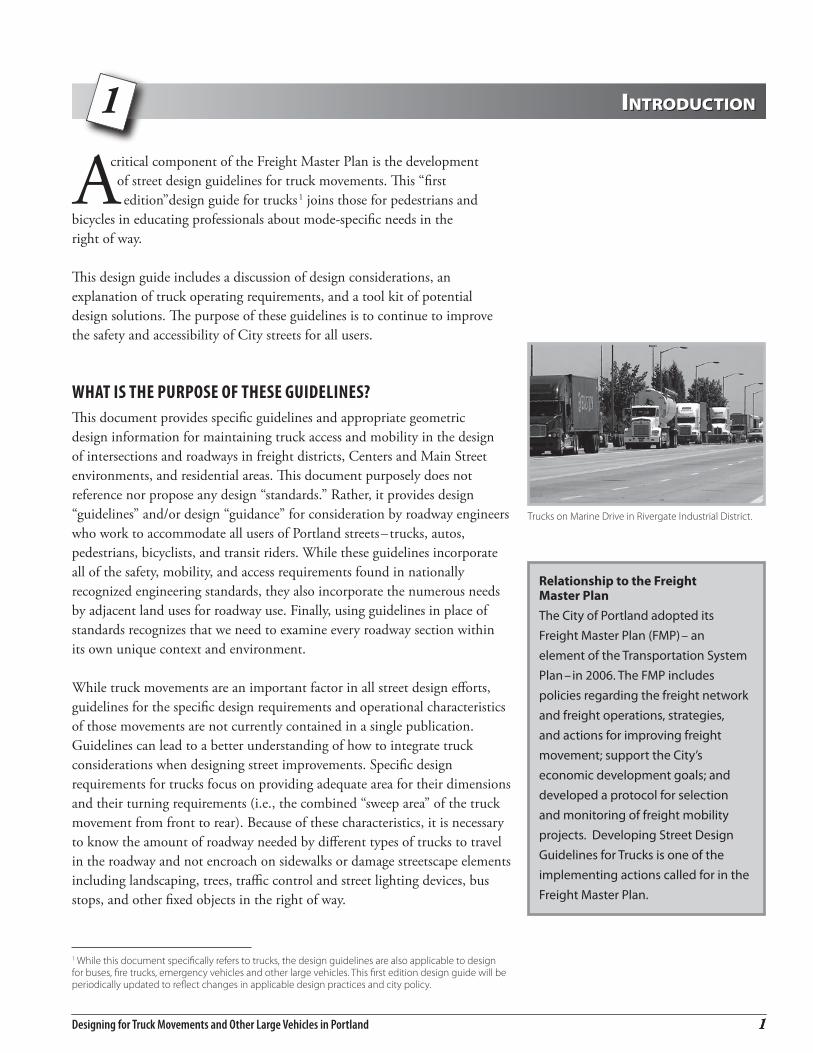
Trucks on Marine Drive in Rivergate Industrial District.
critical component of the Freight Master Plan is the development of street design guidelines for truck movements. This “first edition”design guide for trucks1 joins those for pedestrians and
bicycles in educating professionals about mode-specific needs in the right of way.
This design guide includes a discussion of design considerations, an explanation of truck operating requirements, and a tool kit of potential design solutions. The purpose of these guidelines is to continue to improve the safety and accessibility of City streets for all users.
What is the PurPose of these Guidelines?This document provides specific guidelines and appropriate geometric design information for maintaining truck access and mobility in the design of intersections and roadways in freight districts, Centers and Main Street environments, and residential areas. This document purposely does not reference nor propose any design “standards.” Rather, it provides design “guidelines” and/or design “guidance” for consideration by roadway engineers who work to accommodate all users of Portland streets–trucks, autos, pedestrians, bicyclists, and transit riders. While these guidelines incorporate all of the safety, mobility, and access requirements found in nationally recognized engineering standards, they also incorporate the numerous needs by adjacent land uses for roadway use. Finally, using guidelines in place of standards recognizes that we need to examine every roadway section within its own unique context and environment.
While truck movements are an important factor in all street design efforts, guidelines for the specific design requirements and operational characteristics of those movements are not currently contained in a single publication. Guidelines can lead to a better understanding of how to integrate truck considerations when designing street improvements. Specific design requirements for trucks focus on providing adequate area for their dimensions and their turning requirements (i.e., the combined “sweep area” of the truck movement from front to rear). Because of these characteristics, it is necessary to know the amount of roadway needed by different types of trucks to travel in the roadway and not encroach on sidewalks or damage streetscape elements including landscaping, trees, traffic control and street lighting devices, bus stops, and other fixed objects in the right of way.
Relationship to the Freight Master PlanThe City of Portland adopted its Freight Master Plan (FMP)– an element of the Transportation System Plan–in 2006. The FMP includes policies regarding the freight network and freight operations, strategies, and actions for improving freight movement; support the City’s economic development goals; and developed a protocol for selection and monitoring of freight mobility projects. Developing Street Design Guidelines for Trucks is one of the implementing actions called for in the Freight Master Plan.
1 While this document specifically refers to trucks, the design guidelines are also applicable to design for buses, fire trucks, emergency vehicles and other large vehicles. This first edition design guide will be periodically updated to reflect changes in applicable design practices and city policy.

Designing for Truck Movements and Other Large Vehicles In Portland�
Why are trucks travelinG in my neiGhborhood?Trucks move the goods that are requested by individuals, including deliveries made to department stores, markets and restaurants, manufacturing facilities, office buildings, and even to residences who receive delivery of goods and packages. Trucks come in all shapes and sizes; they range from large semis (delivering to grocery stores and moving vans) to smaller panel trucks that deliver overnight packages to homes or businesses. If trucks are not delivering to you, they likely are delivering to your neighbor. Like school buses, TriMet buses, garbage trucks, fire trucks and other emergency vehicles,2 they have special operating characteristics that need to be accommodated.
Most often, truck deliveries are made to businesses and homes located along streets that also accommodate other transportation modes. The character of Portland’s older, urban commercial and residential streets is challenging for larger vehicles as they provide relatively small street widths and have corners that are difficult for some trucks to negotiate. In order to make deliveries along these streets, trucks may load and unload goods from a travel lane, or from a local side-street using hand trucks to enter stores and homes.
Safety is the most important goal when designing City streets. The City of Portland and the carriers and shippers who move goods throughout the City hope that use of this document will help provide a safer environment for all users of the transportation system.
hoW are these Guidelines to be used?These guidelines are intended for elected officials, planners, engineers, and others interested in street design. The guidelines identify the processes employed and the practices used to develop safe and accessible streetscapes to accommodate truck movements. They also provide the policy basis to assist City traffic engineers and street designers in establishing the appropriate “curb line” or “edge of pavement” for street improvement projects.
different desiGn requirements in different urban environmentsLike all street design efforts, designing for truck movements is completed on a case-by-case basis. In general, providing for truck movements through the City’s various industrial, commercial, and residential districts follows certain principles for different urban environments. For example, because freight districts (such as Rivergate and the Northwest Industrial Districts) accommodate a high volume of trucks, it is important that designers provide lane widths, turning radii, and other street features that can accommodate trucks without impeding their access and ability to maneuver. In contrast, in mixed-use urban areas roadway design must accommodate all modes, which may result in slower and more challenging maneuvers for trucks. Further, there is variation between districts that even have the same designation (e.g., the older Central Eastside Industrial District has relatively narrow intersections compared with the Rivergate Industrial District). The designer cannot simply rely on a list of “design standards;” rather, they must provide a safe and accessible roadway that accounts for all of the specific physical, environmental, and usage characteristics of the area they are working in, as well as integate the needs and objectives of its neighbors. Therefore, these guidelines address Freight Districts, Centers and Main Streets, and Residential Areas separately.
2 In every instance, roadway design must accommodate the needs of fire trucks and other emergency vehicles.
Truck making a local delivery on SE Division St.
Designing for Truck Movements and Other Large Vehicles in Portland �
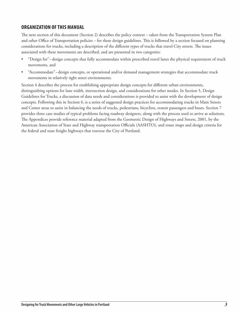
orGanization of this manualThe next section of this document (Section 2) describes the policy context – taken from the Transportation System Plan and other Office of Transportation policies – for these design guidelines. This is followed by a section focused on planning considerations for trucks, including a description of the different types of trucks that travel City streets. The issues associated with these movements are described, and are presented in two categories:
• “Design for”–design concepts that fully accommodate within prescribed travel lanes the physical requirement of truck movements, and
• “Accommodate”–design concepts, or operational and/or demand management strategies that accommodate truck movements in relatively tight street environments.
Section 4 describes the process for establishing appropriate design concepts for different urban environments, distinguishing options for lane width, intersection design, and considerations for other modes. In Section 5, Design Guidelines for Trucks, a discussion of data needs and considerations is provided to assist with the development of design concepts. Following this in Section 6, is a series of suggested design practices for accommodating trucks in Main Streets and Center areas to assist in balancing the needs of trucks, pedestrians, bicyclists, transit passengers and buses. Section 7 provides three case studies of typical problems facing roadway designers, along with the process used to arrive at solutions. The Appendices provide reference material adapted from the Geometric Design of Highways and Streets, 2001, by the American Association of State and Highway transportation Officials (AASHTO), and route maps and design criteria for the federal and state freight highways that traverse the City of Portland.

Designing for Truck Movements and Other Large Vehicles In Portland�

2 Policy BackgrounDPolicy BackgrounD
Designing for Truck Movements and Other Large Vehicles in Portland �
s with all transportation modes, trucks traveling on City streets are encouraged to use certain streets because of their location in the freight network and the land uses they serve. This section describes
the policies that guide planning and design for all transportation modes.
Portland street classifications The Transportation System Plan (TSP) is the City’s policy document that establishes the street classifications for freight and other transportation modes (bicycle, pedestrian, public transit, traffic). The TSP established the following street classifications for freight: Regional Truckway, Priority Truck Street, Major Truck Street, Truck Access Street, Local Truck Street and Freight District Street. These classifications match the designated land uses along these streets. Figure 1 shows the freight street classification system including the highway and street network, rail network, and freight districts.
Roads and streets are classified according to their function in the transportation system. Higher-classified roads such as I-5 and US 26 carry high volumes of traffic over long distances, and have a significant number of large vehicles. Lower-classified roads such as neighborhood streets carry primarily passenger car traffic to and from residential neighborhoods. A description of the function and design objectives for the freight street classification system is shown in Table 1.
Freight Street Designations Example
Regional Truckway I-5, US 26, US 30, I-205
Priority Truck Street Marine Dr, Columbia Blvd
Major Truck Street Sandy Blvd, Powell Blvd
Freight District Street Leadbetter Rd, Water Ave
Truck Access Street Fremont St, Division St
Local Truck Street Streets outside freight districts
balancinG other transPortation modesMost Portland arterial and collector streets have multiple designations, and designers must ensure that they have considered all of the functions incorporated into the street. For example, NE Sandy Blvd is designated as a Major Truck Street, Major City Transit Street, Major City Traffic Street, and City Bikeway and City Walkway. Each of these modal designations are part of a city-wide street network for each mode, and designers must incorporate each mode’s needs at each site examined to ensure continuity. Chapter 2 of the Transportation System Plan identifies all street designations, and the considerations associated with them.
Truck exiting T-6 in Rivergate Industrial District.
On-street loading in downtown Portland.

Designing for Truck Movements and Other Large Vehicles In Portland�
table 1definition of Portland’s freight street classification system
Classification* Function Application Design Objectives**
Regional Truckway
Routes for interregional and interstate movement of freight. Provide for safe and efficient continuous-flow operation for trucks.
Applied to roadways with inter-state or inter-regional truck movement: I-5, I-84, I-205, I-405, US 26, and US 30, 99E.
Design Regional Truckways to be limited access facilities and to standards that facilitate the movement of all types of trucks.
Priority Truck Street
Serve as primary routes for access and circulation in Freight Districts, and between Freight Districts and Regional Truckways. Accommodate high truck volumes and provide high-quality mobility and access.
Applied to major city traffic streets in industrial districts and that connect industrial districts to the regional system: N. Marine Dr., NE Columbia Blvd., NW St. Helens Rd.
Priority Truck Streets should be designed to facilitate the movement of all truck classes and over-dimensional loads, as practicable.
Major Truck Street
Serve as principal routes for trucks in a Transportation District. Provide truck mobility and access to commercial and employment uses along the corridor.
Applied to commercial areas of major city traffic streets, arterial connections to central city, regional, and town centers: NE MLK Blvd., NE Sandy Blvd., SE Powell Blvd.
Major Truck Streets should accommodate all truck types, as practicable.
Freight District Street
Freight Districts are determined by presence of industrial sanctuary zoning (IG1, IG2 & IH). Freight District Streets are intended to provide safe and convenient truck mobility and access in industrial and employment areas serving high levels of truck traffic and to accommodate the needs of intermodal freight movement.
Applied to all streets in freight districts, unless classified with a higher designation.
Freight District streets should be designed to facilitate the movement ofall truck types and over-dimensional loads, as practicable.
Truck Access Street
Serve as access and circulation routes for delivery of goods and services to neighborhood-serving commercial and employment uses. Provide access and circulation to land uses within a Transportation District. Non-local truck trips are discouraged from using Truck Access Streets
Applied to commercial corridors along collector streets that serve neighborhoods: NE Fremont St., NE. Halsey St., SE Division St., SE Woodstock Blvd.
Design Truck Access Streets to accommodate truck needs in balance with other modal needs of the street.
Local Truck Street
Provides local truck access and circulation for goods and service delivery to individual locations in neighborhoods.
Applied to local streets outside freight districts to provide access/circulation for goods and service delivery.
Should give preference to accessing individual properties and the specific needs of property owners and residents along the street. Use of restrictive signage and operational accommodations are appropriate.
* Adopted by Portland City Council on May 10, 2006 as part of the Freight Master Plan. **Design Objectives adopted as part of the Transportation System Plan: see Volume 1, Chapter 2 of the TSP.
Designing for Truck Movements and Other Large Vehicles in Portland �
Like most street design efforts, designing for truck movements typically required balancing the needs of other, and sometimes competing, transportation interests. It is essential to note that engineers have many choices to make in designing roadways and intersections. For example, there may be limiting factors at the site such as natural or man-made impediments, community needs and objectives, and the available budget and maintenance considerations.
In addition, when focusing on particular sites and corridors, designers need to take a broad view of how trucks, cars, bikes, pedestrians and buses travel to and from the site or corridor under investigation. Without taking a larger view of a problem(s), the designer runs the risk of correcting only one of several problems in a corridor (e.g., providing an 11.0’ lane width for one block face, while the block faces before and after have 12.0’ to 10.0’ lanes). In addition, a broader system view might result in solutions that rely more on system management, signage, etc. rather than construction solutions.
Relationship with FedeRal and state policyThe guidelines and design considerations described in this document are for the purposes of designing streets owned and maintained by the City of Portland. However, many of the streets traversing the City are owned and operated by the Oregon Department of Transportation (ODOT), and must be designed to meet criteria and guidelines established by ODOT. Some City streets and State Highways are designated by the federal government as National Highway System (NHS) routes and intermodal connectors, and segments of the National Network (NN) System. Where streets or highways have these federal NHS or NN designations, the federal design guidelines (administered by ODOT) are typically applied when federal funds are being used. In addition, State highways designated as Freight Routes in the Oregon Highway Plan and those on the National Network are subject to ORS 366.215, which states that Oregon Transportation Commission (OTC) approval is required for any reductions in capacity on identified freight routes. An ODOT Procedure for implementing this statute is under development and designers should coordinate with the ODOT Region Planner and/or Mobility Liaison for further advice about compliance with this statute (see http://landru.leg.state.or.us/ors/366.html).
For more information about the federal and state facilities, their functions, and maps of their routes, see Appendix A.

Designing for Truck Movements and Other Large Vehicles In Portland�

Designing for Truck Movements and Other Large Vehicles in Portland 9
NE SANDY BLVD
SE POWELL BLVD
SE82
ND
AVE
SE STARK ST
SWBARBUR BLVD
NE
82N
DAV
E
NE
122N
DAV
ESE
122N
DAV
E
SE12
THAV
E
NE
MAR
TIN
LUTH
ERKI
NG
JRBL
VD
SE WASHINGTON ST
NWBRIDGE
AVE
NE
GR
AND
AVE
SWBERTHA
BLVD
SWM
ACADAMAVE
ROSS ISLAND BRG
NWFRONT AVE
NE
12TH
AVE
BROADWAY BRG
NW
16TH
AVE
SWM
ACADAMAVE
N MARINE DR
NE AIRPORT WAY
N COLUMBIA BLVD
NE COLUMBIA BLVD
NW FRONT AVE
NE LOMBARD ST
NLO
MBAR
DST
NPORTL
ANDRD
NWST
HELENSRD
NE CORNFOOT RD
N GOING ST
NE
82N
DAV
E
SE17
THAV
E
NGREELEY AVE
NE KILLINGSWORTH ST
NE12
2ND
AVE
NW26TH
DR
NHAYDEN
ISLA
NDBRID
GE
NLO
MBARD
ST
SE DIVISION ST
N LOMBARD ST
NE HALSEY ST
SE39
THAV
E
NE GLISAN ST
NE
33R
DAV
E
SE52
ND
AVE
NE
102N
DAV
E
NIN
TER
STAT
EAV
E
SE WOODSTOCK BLVD
NE FREMONT ST
SE16
2ND
AVE
SW MULTNOMAH BLVD
NE
42N
DAV
E
SE HOLGATE BLVD
NE BROADWAY ST
SE12
2ND
AVE
E BURNSIDE ST
NE ALBERTA ST
SE BELMONT ST
SE FOSTER RD
SEM
ILWAU
KIEAVE
SE50
THAV
E
SW BOONES FERRY RD
SWSHATT
UCKRD
NE
39TH
AVE
NE
60TH
AVE
NE
162ND
AVENKE
RBY
AVE
SW6T
HAV
E
SW13
THAV
E
SW CAPITOL HWY
KERRRD
SE FOSTER RD
SWCA
PITO
LHW
Y
NE HALSEY ST
SE DIVISION ST
26
5
5
5
8484
84
205
205
205
217
FREIGHT MASTER PLAN (7/25/06)
Brooklyn Yard
East Portland
Central Post Office
Graham
Willbridge
Terminal-4
Linnton Barnes Yard
Kenton
South Rivergate
Terminal-5 North Rivergate
Terminal-6
Fir
PDX Cornfoot Portland Int. Airport
Freight ClassificationsRegional Truck WayPriority Truck StreetMajor Truck StreetTruck Access StreetFreight District StreetLocal Service Truck StreetMain Rail LineBranch Rail
Freight Facilities
Freight District
Urban Service Area
NWFRONT AVE
NW FRONT AVE
NWST HELENS
RD
NW NICOLAI ST
N GOING ST
NW26TH
DR
Terminal-2
Lake Yard
AlbinaYard
NW Container Serv
Inset
Inset
Figure 1PORTLAND FREIGHT NETWORK MAP


3 Planning consiDeraTions for TrucksPlanning consiDeraTions for Trucks
Designing for Truck Movements and Other Large Vehicles in Portland ��
Dimensions of Typical Design Vehicles
figure 2truck types/design vehicles
The Portland Fire Bureau reference a WB-40 as a comparable design vehicle to a city fire truck.
Planning for trucks in the built or unbuilt environment requires an understanding of the physical characteristics of trucks, the physical impediments in the environment, and where and when we can or
cannot address all of these factors.
tyPes of trucks (desiGn vehicles)The size and shape of a truck is determined by the goods or materials being hauled and the distance that they travel. The American Association of State Highway and Transportation Officials (AASHTO) has developed a classification system that identifies trucks by their approximate height, width, and length. This classification ranges from the SU-30 Single Unit truck (e.g., cement trucks, large rental trucks, local delivery trucks) to the WB-67 Interstate truck (large semi-trailer with sleeper cab equipped tractor; this class also includes double and triple trailer combinations). Figure 2 3 shows the typical dimensions of the AASHTO standard vehicles referenced in these guidelines. Additional information on these and other design vehicles can be found in the AASHTO Policy on Geometric Design of Highways and Streets. Table B-1 in Appendix B summarizes truck design characteristics from AASHTO.
“design for” versus “accommodate” approaches to addressing truck accessIn the design of an intersection, it is essential to identify the size and type of trucks that will be using the intersection. Current and future use of adjacent property, roadway classification, truck route designation, and the need for a truck to turn at a particular intersection versus taking another more accessible route are some of the applicable information needed to assess the level of truck activity. Guidance in selecting a “design vehicle” is provided in Section 5 and Appendix D.
With an understanding of the expected truck type, the designer evaluates the turning track maneuvers of a vehicle using AASHTO turning templates or specialized computer software such as AutoTURN 4 (see Figure 3), including the path followed by the corners of the vehicle body or trailer, as well as the inside rear wheels. For a typical passenger vehicle, the path followed by the rear wheels is almost the same as that of the front wheels. With larger vehicles, the swept area becomes much larger as the inside rear wheels track substantially inside of the path of the front wheels. This becomes the most critical factor in sizing the intersection.
3 For more information on city buses, refer to “Planning and Design for Transit Handbook, Guidelines for implementing transit supportive development, Tri-Met, January1996.” 4 AutoTURN is a registered trademark of Transoft Solutions.
Designing for Truck Movements and Other Large Vehicles In Portland1�
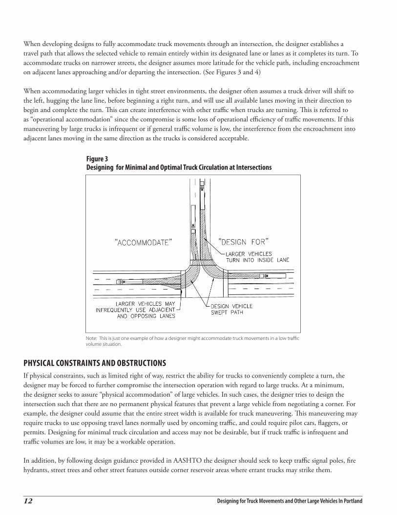
When developing designs to fully accommodate truck movements through an intersection, the designer establishes a travel path that allows the selected vehicle to remain entirely within its designated lane or lanes as it completes its turn. To accommodate trucks on narrower streets, the designer assumes more latitude for the vehicle path, including encroachment on adjacent lanes approaching and/or departing the intersection. (See Figures 3 and 4)
When accommodating larger vehicles in tight street environments, the designer often assumes a truck driver will shift to the left, hugging the lane line, before beginning a right turn, and will use all available lanes moving in their direction to begin and complete the turn. This can create interference with other traffic when trucks are turning. This is referred to as “operational accommodation” since the compromise is some loss of operational efficiency of traffic movements. If this maneuvering by large trucks is infrequent or if general traffic volume is low, the interference from the encroachment into adjacent lanes moving in the same direction as the trucks is considered acceptable.
figure 3 designing for minimal and optimal truck circulation at intersections
Figure 1b: Designing for Minimal and Optimal Truck Circulation at Intersections. Note: This is just one example of how a designer might accommodate truck movements in a low traffic volume situation.
Note: This is just one example of how a designer might accommodate truck movements in a low traffic volume situation.
Physical constraints and obstructionsIf physical constraints, such as limited right of way, restrict the ability for trucks to conveniently complete a turn, the designer may be forced to further compromise the intersection operation with regard to large trucks. At a minimum, the designer seeks to assure “physical accommodation” of large vehicles. In such cases, the designer tries to design the intersection such that there are no permanent physical features that prevent a large vehicle from negotiating a corner. For example, the designer could assume that the entire street width is available for truck maneuvering. This maneuvering may require trucks to use opposing travel lanes normally used by oncoming traffic, and could require pilot cars, flaggers, or permits. Designing for minimal truck circulation and access may not be desirable, but if truck traffic is infrequent and traffic volumes are low, it may be a workable operation.
In addition, by following design guidance provided in AASHTO the designer should seek to keep traffic signal poles, fire hydrants, street trees and other street features outside corner reservoir areas where errant trucks may strike them.

Designing for Truck Movements and Other Large Vehicles in Portland ��
figure 4 turning requirements for different design vehicles
Figures not to scale. These example turning requirements are for 30.0’ radius intersections (i.e., 90 degree grid street layouts. There are many different radius corner lengths in the City of Portland, which require different treatments including mountable curbs for turns with larger radius length.
su-30 city bus
Wb-50 Wb-40
Wb-67 Wb-62

Designing for Truck Movements and Other Large Vehicles In Portland1�
over-dimensional load considerationsOver-dimensional loads are an important form of freight movements within Portland. These movements involve hauling frequent commodities, such as construction cranes and excavators, to less common items like industrial transformers and windmill blades. Because not all routes can accommodate them, it is important to consider these types of movements, especially when the loads are significantly over legal height. When a vehicle has a travel height over 17 feet, routing can be very challenging and may require out of direction travel to avoid height restricted bridges or other physical constraints within the right of way. The Portland Truck Map provides information on designated pilot car routes in the City.
The Oregon Department of Transportation (ODOT) requires trucks transporting oversize or overweight loads to obtain a variance permit prior to departure for loads originating in-state or entering Oregon from another state. Under Oregon Revised Statue (ORS) 818–Vehicle Limits, drivers operating on Oregon roads must obtain a state-issued over-dimensional (single-trip or annual) variance permit to haul any single, non-divisible load meeting the following condition:
Truck operators must obtain an over-dimensional variance permit from the State when their vehicle exceeds any of the legal limits. The permits provide routing plans and restrictions on travel. The City of Portland also requires a permit for the use of city streets by over-dimensional vehicles exceeding the weight or size limitations set forth in ORS 818.
Since few roadways can accommodate over-dimensional loads, it is critical that the clearances of the existing routes be protected. The Portland Office of Transportation (PDOT) is currently developing a strategy for over dimensional loads throughout the City.
Height Vehicle or vehicle combination and load exceeds 14 feet
Width Load or hauling equipment exceeds 8 feet 6 inches
Length Load greater than 40 feet, exceeding 5 feet beyond the end of the semi-trailer, or load less than or equal to 40 feet, exceeding one-third of the wheelbase of the combination, whichever is less
Truck hauling over-dimensional load of construction equipment.
Union Pacific Railroad bridge over Columbia Blvd just west of I-5.
Truck hauling a 155-foot windmill blade destine to a commercial windfarm in eastern Oregon. photo courtesy of PGE

4 Design consiDeraTions in DifferenT urBan environmenTsDesign consiDeraTions in DifferenT urBan environmenTs
Designing for Truck Movements and Other Large Vehicles in Portland ��
Trucks rely on an interconnected street network for providing access between the freeway system and important freight generators, such as marine ports, airports, rail yards, and industrial districts. The street
network also provides access and circulation to the city’s various commercial and residential areas.
Roadway designers must apply sound design principles within different urban environments to address a variety of multi-modal transportation needs. Particularly in the built environment, designers must consider a variety of design requirements and restrictions for developing optimal solutions. In general, providing for truck movements through the City’s various industrial, commercial, and residential districts follows certain design principles for different urban environments.
A. Freight Districts Streets within freight districts experience relatively high volumes of truck traffic including many interstate trucks. They require lane widths, turning radii, and other street features that can accommodate trucks without impeding their access and ability to maneuver. Portland has a variety of different freight district types, from older districts such as the Central Eastside Industrial District with relatively narrow intersections and small-block development pattern to newer districts such as Rivergate with wider right-of-ways. Truck design related guidance and considerations differ from district to district.
B. Centers and Main Streets Streets within these environments–which are defined as mixed-use areas in Metro’s adopted Region 2040 Plan–provide access for trucks serving businesses located within these districts and access to and from the highway system. Designing for truck movements should not conflict with the needs of pedestrians, bicyclists, transit users, and motorists in these areas. A more detailed discussion of the functional uses of Centers and Main Streets is provided in the Street Design Classifications (Policy 6.11, Volume 1, Chapter 2) of the Portland Transportation System Plan.
C. Residential Areas These environments experience low volumes of truck traffic and are principally designed for automobile, pedestrian, and bicycle movements. Apart from fire trucks and garbage trucks, most trucks entering residential areas are smaller-sized delivery trucks and the occasional moving van. Design for truck movements is intended to provide for slow speeds and loading that often occurs on-street.
Freight Districts are to trucks what a Main Street is to a shopper: Freight districts are designed with wider roadways and larger intersections so trucks can easily enter and exit. Main Streets are designed with wide sidewalks, medians, landscaping, and convenient storefront access so shoppers can easily enter and exit stores with goods they purchase. Both environments are specifically designed for their intended user and place a priority on convenience and accessibility.
Hawthorne Boulevard-a Truck Access Street-provides access to neighborhood commercial districts in balance with other transportation modes.
Barbur Boulevard-a Major Truck Street-provides truck mobility and access to commercial and employment areas in SW Portland.
Designing for Truck Movements and Other Large Vehicles In Portland1�
D. Infill Development and Redevelopment within Historic Districts These developments often occur in areas that have relatively narrow travel lanes and limited curb radii, which can impede truck movements. As with Centers and Main Streets and Residential Areas, roadway design must provide access for trucks in a dense urban environment with tight geometry.
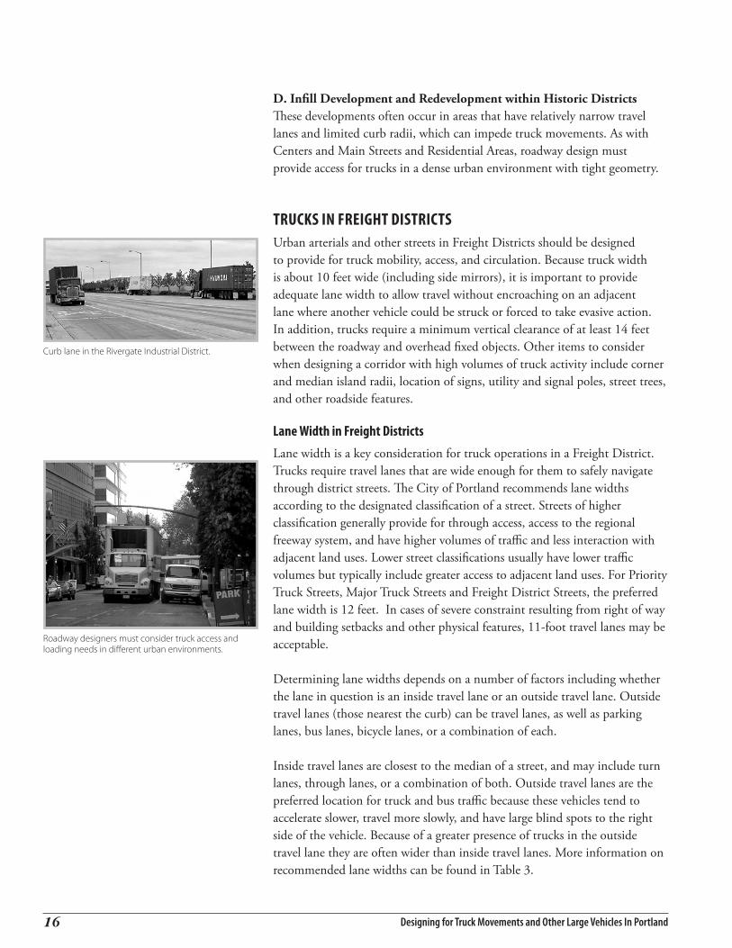
trucks in freiGht districtsUrban arterials and other streets in Freight Districts should be designed to provide for truck mobility, access, and circulation. Because truck width is about 10 feet wide (including side mirrors), it is important to provide adequate lane width to allow travel without encroaching on an adjacent lane where another vehicle could be struck or forced to take evasive action. In addition, trucks require a minimum vertical clearance of at least 14 feet between the roadway and overhead fixed objects. Other items to consider when designing a corridor with high volumes of truck activity include corner and median island radii, location of signs, utility and signal poles, street trees, and other roadside features.
lane Width in freight districtsLane width is a key consideration for truck operations in a Freight District. Trucks require travel lanes that are wide enough for them to safely navigate through district streets. The City of Portland recommends lane widths according to the designated classification of a street. Streets of higher classification generally provide for through access, access to the regional freeway system, and have higher volumes of traffic and less interaction with adjacent land uses. Lower street classifications usually have lower traffic volumes but typically include greater access to adjacent land uses. For Priority Truck Streets, Major Truck Streets and Freight District Streets, the preferred lane width is 12 feet. In cases of severe constraint resulting from right of way and building setbacks and other physical features, 11-foot travel lanes may be acceptable.
Determining lane widths depends on a number of factors including whether the lane in question is an inside travel lane or an outside travel lane. Outside travel lanes (those nearest the curb) can be travel lanes, as well as parking lanes, bus lanes, bicycle lanes, or a combination of each.
Inside travel lanes are closest to the median of a street, and may include turn lanes, through lanes, or a combination of both. Outside travel lanes are the preferred location for truck and bus traffic because these vehicles tend to accelerate slower, travel more slowly, and have large blind spots to the right side of the vehicle. Because of a greater presence of trucks in the outside travel lane they are often wider than inside travel lanes. More information on recommended lane widths can be found in Table 3.
Curb lane in the Rivergate Industrial District.
Roadway designers must consider truck access and loading needs in different urban environments.

Designing for Truck Movements and Other Large Vehicles in Portland ��
intersection design in freight districtsIntersection design in Freight Districts must consider the largest truck type, which is typically a WB-67. With a 53 foot-long trailer, a WB-67 requires enough maneuvering room to complete a right turn without encroaching into the travel lanes of opposing traffic, and enough turning area to avoid mounting curbs or sidewalks. The key design element to keep a truck within the confines of its travel lanes is the radius of the curb. In Freight Districts, curb radii are typically designed for these truck movements.
Figure 5 illustrates the truck turning movements for a WB-50 truck. (Illustrations for Buses, SU-30, WB-40, WB-50, WB-62, and WB-67 can be found in Figure 4) The figure illustrates a right turn by a WB-50 truck into the inside or non-curb lane. If for safety and traffic operations reasons it is undesirable to allow the truck to turn into an inside travel lane, it may be necessary to build the curb radius to something larger than shown in Figure 5. This figure assumes 12 foot travel lanes and an adjacent 6 foot bicycle lane. The desire is to design for the curb radii to accommodate the design vehicle.
Where bicycle lanes are not provided, a standard 8 foot parking lane would produce a similar effect to truck turning movements, but would reduce the minimum curb radius by 2 feet, assuming no curb extensions were included at corners. The absence of bicycle lanes or parking lanes would increase the minimum curb radius.
A truck driver’s ability to negotiate a right turn is improved by hugging the street centerline or moving left into the adjacent lane before beginning a right turn.
The Oregon Revised Statutes (ORS) vehicle code requires that vehicles turn into the nearest lane when making a left turn. For a right turn, the vehicle code requires a turn be made from “as close as practicable to the right-hand curb or edge of the roadway,” but it does not prescribe the lane into which a vehicle turns. The vehicle code further prescribes that a vehicle be operated “as nearly as practicable entirely within a single lane.” “Practicable” is not defined by the code, but intruding on adjacent lanes or turn the second lane when making right turns is common practice, and is often the only reasonable solution. If there is only a single lane on the street, truck drivers have little maneuvering room when making right turns. When corner radii are tight, truck drivers are faced with intruding into the adjacent on-coming traffic lane or letting the trailer run over the curb, or both.
Corner islands, which are sometimes used for channeling or separating right turns, often present a challenge to truck drivers. An island eliminates pavement that would be occupied by the cab as a truck driver seeks to keep the right rear of the trailer from running up on the curb. In Freight Districts, however, a corner island can still be beneficial to mitigate the long pedestrian
figure 5Wb-50 right turn into non-curb lane
Truck entering the St Johns Bridge-part of the National Highway System network.

Designing for Truck Movements and Other Large Vehicles In Portland1�
crossing distances created by designing for large trucks. In such situations, the corner and island must be designed for the WB-67 sized truck (see Section 6- Suggested Design Practice #5).
While procedural guidelines can be developed to provide general direction for design of intersections for trucks, the final configuration and best overall design of an intersection must still be completed by experienced designers. Basic geometric considerations such as the angle at which the roads intersect, the presence of buildings abutting the right of way, and use of right-turn lanes will vary from intersection to intersection. The surrounding land use, existing development patterns, and other factors could also influence specific decisions about intersection design.
Pedestrian, bicycle, and transit considerations in freight districtsWhile truck circulation is an important design principle, Freight District streets must also safely and conveniently accommodate and balance the needs of pedestrians, bicyclists, and buses. There are no standard solutions for resolving truck conflicts with other modes. Each situation needs to be evaluated separately on a case-by-case basis. An illustrative example of mitigating potential truck/bicycle conflicts is shown in Figure 6.
A. Pedestrian Crosswalks, median refuge islands, and curb extensions are three design elements that assist pedestrians in urban environments. In Freight Districts, however, these design elements can impede truck movements. With wider intersections for truck turning movements, pedestrians may have longer crosswalks to negotiate at intersections and curb extensions may not be possible. Longer crossing times may be needed for pedestrians. On wider roadways, pedestrian median refuges may need to be designed with mountable curbs and pedestrians need to be aware of large vehicles turning into the road they intend to cross.
B. BicyclesBicycles in Freight Districts also require special consideration at intersections. As seen in Figure 5, trucks can encroach on the bicycle lane in right-turn movements. Dedicated right-turn lanes for trucks are preferable in these situations (see Figure 6) as they allow for the bicycle lane to transition to the left of the right-turn lane, and minimizes potential truck/bicycle conflicts. Designers must recognize that a truck driver’s vision is limited when making right turns at intersections. This is a particularly important consideration wherever trucks turn right across bicycle lanes.
In several areas of Portland, bicycles and motor vehicles share vehicle lanes. This shared lane concept is discouraged in freight districts where there are significant truck and/or bicycle volumes.
figure 6 bicycles Protected from trucks left of dedicated right turn lane
Pedestrian crossing over N Columbia Blvd-a Priority Truck Street serving the Rivergate Industrial District.

Designing for Truck Movements and Other Large Vehicles in Portland ��
Other design and route concepts for bicycles and pedestrians in freight districts include physical separation through raised curbs and/or grade-separation and alternate bicycle and pedestrian routes to, from and within industrial districts.
C. Transit From an operational perspective, transit circulation in Freight Districts is generally compatible to truck circulation. Similar to trucks, buses require wider lanes and more generous curb radii for right-turn movements. However, potential conflicts with trucks need to be considered where passengers access bus stops and LRT stations and at pedestrian crosswalk locations.
Easy and convenient pedestrian access needs to be considered wherever a bus stop or LRT station is located and where truck operations are being addressed. In Freight Districts, transit stops should be located within a short walking distance from major employment centers and other areas that can generate a high number of potential transit riders. Transit stops should be located to balance good passenger access with pedestrian safety. Stop locations should minimize the potential for jaywalking, minimize passenger walking distance and avoiding unnecessary crosswalk movements.
In respect to light rail and streetcars which run on a fixed guideway system, the location and height of the overhead catenary wires need to be considered to allow adequate clearance for truck movements.
Adjacent land uses must also be taken into consideration when balancing the needs between truck movements and those of pedestrians, bicyclists, transit vehicles and passengers. It is preferable to locate pedestrian and bicycle routes closest to the land uses with the highest intensity of employees and cyclists. Where feasible, transit stops should be located by the main entrances of industrial and commercial complexes and business centers.
trucks in centers and main street areasPortland is known for its mixed-use pedestrian and bicycle-friendly neighborhoods. Centers and Main Streets are hubs of mixed-use activities hosting a variety of commercial and retail shops, restaurants, and residences.
The key to street design in Center and Main Street areas is balancing the needs for truck access with the need for pedestrian safety and convenience.Conflicts may occur when businesses rely on trucks to deliver the goods they need to serve their customers. Common features that benefit pedestrians, such as narrow streets, curb extensions, high volumes of pedestrians, and parked cars, can also impact the ability for trucks to maneuver.
Trucks mixed with local traffic in the St Johns Town Center.
Potential conflicts with trucks should be considered when passengers access bus stops and at pedestrian crosswalks.

Designing for Truck Movements and Other Large Vehicles In Portland�0
In some instances, deliveries to businesses in these locations can be completed with smaller trucks. Their compact size and tight turning radius make them suitable for narrow street geometries and local deliveries. Typical trucks include the SU-30 and WB-40 truck types. However, there are times when larger trucks such as a WB-67 must circulate in Center and Main Street areas and these situations need to be accommodated during the street design process. The key design elements that need to be considered for the occasional large truck are lane widths and intersection design.
lane Width in centers and main street areasLane widths on streets within Centers and along Main Streets are typically narrower and may feature pedestrian enhancements that improve safety and manage vehicle speeds. The “preferred” lane width on Major Truck Streets (such as NE Sandy Blvd) is 12 feet, with 11 feet acceptable. Truck Access Streets (such as SE Belmont Ave) may have minimum inside lane width of 11 feet, with recommended outside lane widths of 11 to 12 feet.
intersection design in centers and main street areasTruck access must be provided for business deliveries and connections to the arterial street network. Intersections are the most challenging location for truck operations in these areas.
Figure 7 illustrates how a WB-67 truck negotiates a right-hand turn onto a four-lane street with a 15 foot turning radius. Note that the truck has to position to the left and use as much space as possible to turn the trailer into the desired direction.
Figure 8 illustrates how a WB-67 truck completes a right-turn into a two-lane street. This is one of the most difficult street conditions a truck driver faces. Note how much of the on-street parking space the truck requires to complete the turn.
trucks in residential areasPortland’s residential neighborhoods, such as Laurelhurst, Sellwood, Multnomah Village, and Kenton, are principally designed for automobile, pedestrian and bicycle movements, and low volumes of truck traffic. While occasional large delivery trucks and moving vans travel in these areas, the more common truck type is smaller-sized delivery trucks. The streets serving residential areas are classified for local truck vehicles, and they are not intended for through truck trips. Trucks in these areas travel at relatively slow speeds and conduct loading from the right-of-way or residential driveway locations.
Example of Center and Main Street Areas
Center Areas Main Street Areas
Downtown Portland SE Belmont St
Gateway SW Capitol Hwy
St Johns Town Center NE Broadway St
Hollywood District SE Hawthorne Blvd
Multnomah Village NE Sandy Blvd
figure 7illustration of large truck at four-lane intersection
Right-hand turn by a WB-67 truck into a four-lane street with 15’ curb radius.
Right-hand turn by a WB-67 truck into a two-lane street with 15’ curb radius.
figure 8illustration of large truck at two-lane intersection

Designing for Truck Movements and Other Large Vehicles in Portland 2�
Immediately abutting some of the City’s residential neighborhoods are commercial streets (e.g., the Ladd’s Addition area framed by SE Hawthorne Blvd and SE Division Street), which may have more truck traffic than residential neighborhoods and larger transition zones between residential and commercial land uses. Some residential neighborhoods contain retail businesses (such as the stores and restaurants along NE Prescott in the Concordia neighborhood), and experience truck traffic servicing those establishments. Other residential neighborhoods (such as Liar Hill) contain a number of mixed-use residential and commercial uses, which encounter truck movements to serve those non-residential uses.
Many residential neighborhoods are centered around schools and religious institutions, which receive deliveries and use school buses for many of their activities.
lane Width in residential areasLane widths on streets within residential areas are relatively narrow and may feature on-street parking on one or both sides of the street. The combination of these elements leads to slow speeds (typically under 25 mph), and in many instances, traffic calming devices (such as raised center islands, landscaping treatments, rumble strips, and speed bumps) to reinforce the speed limits and improve pedestrian safety. The minimum lane width in residential areas depends, in part, on the density allowed in the underlying zoning category. For R-5 zoning and higher densities, the minimum lane width for residential streets with parking on both sides is 32 feet. However, many streets are as narrow as 20 feet with and without parking on one side. Trucks and buses range in width from 9 to 10 feet, and require 1.5 foot clearance on both sides from curbs, parked cars, and other physical obstructions; or needing as much as 13 feet for passage.
intersection design in residential areasPedestrians, bicycles, and automobiles are the primary transportation modes in residential areas. Similar to Centers and Main Streets, truck movements are complicated by limited curb radii, narrow roadways, and parked vehicles near intersections.
When big trucks travel on residential streetsThere are some residential streets that have occasional or even weekly large truck traffic. This occurs more frequently on streets around a shopping center. If a truck loading area is located near the rear of the building, trucks will need to use the local streets to access the loading dock.
Small delivery truck on a local City street.

Designing for Truck Movements and Other Large Vehicles In Portland��

5 Design guiDelines for TrucksDesign guiDelines for Trucks
Designing for Truck Movements and Other Large Vehicles in Portland 2�
This section provides a list of design considerations and suggested design practices for consideration by engineers, architects, designers, planners and others involved in street design land developments, and
streetscapes that require access by trucks.
Plan for trucks early in the ProcessTruck circulation should be considered early in the conceptual development of street design, as well as in the conceptual stages of a land use development proposal. During street design, consideration should be given to the level of truck access along a street and to and from properties (including access to on- and off- street loading facilities). Adjacent street characteristics such as roadway classification, lane width, and the design of existing intersections, need to be carefully examined to evaluate their suitability for the types of trucks that are needed for businesses. This is particularly important in existing urbanized areas outside of Freight Districts where conflicts with trucks are more likely to occur. Other land uses in the area that use trucks should also be noted.
checklist of information needed by desiGners It’s essential that designers have a comprehensive understanding of the function and use of the streets and intersections they are designing for. This understanding is gained through research of the roadway location and observations made in the field.
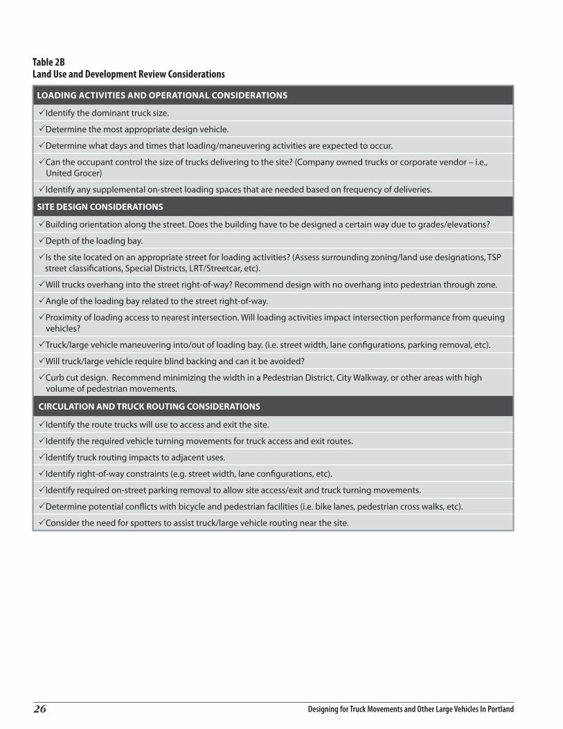
A checklist of engineering and development review considerations to assist roadway designers in their reconnaissance and development activities is provided in Table 2A and Table 2B. In many cases, additional information beyond these considerations will need to be gathered, and in other cases, less information will be needed. The checklists are intended as a basic template for the designer’s use.
Talking to Business Owners When designing a street improvement in a location that will be used by trucks, talk to businesses in the neighborhood. Ask them if there are any truck-related neighborhood or circulation issues. Look for signs of trucks in the area– traffic control signs, black tire marks on curbs, designated loading zones, and loading docks–to gain insight into local truck operations.
Fixed Guideway Transit FacilitiesWhen designing truck access across and adjacent to fixed guideway transit facilities such as Light Rail or Streetcar, where parts of existing streets are dedicated for transit, an analysis of truck movements should be made to ensure that trucks entering the transit street can make their turn(s) without encroaching into the transit right-of-way.
roadWay desiGnlane WidthA variety of factors are considered when designing lane widths. Some include existing constraints within the right of way-such as building orientation, curb and sidewalk location and on-street parking - right of way acquisition needs, current and projected traffic volumes, the presence of high volumes of bicycle and pedestrian use, vehicular capacity needs, and the number of travel lanes. The checklists shown in Table 2A and Table 2B identifies some of the factors and data needs that are considered for lane width design.

Designing for Truck Movements and Other Large Vehicles In Portland24
Table 2ARoadway Design Engineering Considerations
PHYSICAL CONSIDERATIONS
PCross-sections– lane widths, curb radii, on-street parking, loading, setback, vertical/horizontal clearances, turn lanes, existing striping.
PHorizontal alignment (linear vs. multiple curves).
PDetermine “shy distance” requirements.
PReview roadway maintenance records.
PIdentify the posted and/or design speed along the street corridor.
PCurrent and projected traffic flow (volumes, mode split, vehicle classification).
PCurrent and projected volumes of bicycle and pedestrian traffic.
PIntersection and signal operation: • Stop or signal • Speed of turning Vehicle • Sight lines
PRight of way acquisition needs.
PIdentify existing wetlands, wildlife habitat or stream crossings.
PIdentify topographic constraints.
PDetermine stormwater drainage requirements.
POLICY AND ROADWAY CONSIDERATIONS
PIdentify TSP functional classifications: 1. Traffic 5. Freight 2. Transit 6. Emergency Response 3. Bicycle 7. Street Design 4. Pedestrian
PIdentify geometric requirements for TSP street classifications.
PReview TSP to determine other roadway considerations for the project area.
PDetermine whether location is in a special district (Freight, Pedestrian, and Central City).
PDetermine if roadway is a State Highway and/or classified as a NHS or National Network facility.
PIdentify surrounding zoning/land use designations.
PLane width considerations: • Distance from lane line to curb • Parking lane width (7’ minimum or 8’ minimum if bus/loading zones or adjacent to streetcar) • Bike lane width (5’ preferred and 6’ desirable) • Sidewalk corridor width (per Pedestrian Design Guide)
PDetermine the desired roadway operation (e.g., local service truck street, over-dimensional truck route, etc).
PIdentify other existing traffic studies of the project area.
PConsider how traffic currently uses and is projected to use the street, and, generally, from where that traffic originates or is destined.
PConsider requirements of the project’s funding source and related budgetary constraints.
PConsider scale of the project (e.g. single intersection or long roadway segment).

Designing for Truck Movements and Other Large Vehicles in Portland 2�
CONSIDERATIONS TO OBSERVE IN THE FIELD
PCurrent traffic volumes and vehicle types.
PObserve different approaches to intersections.
PDominant truck size (e.g. WB67, SU30).
PPresence of bike lanes.
PIdentify sight distance issues.
PIdentify any street/sidewalk amenities and impediments.
PObserve ability for vehicles to negotiate corners.
PCurb return radius considerations: • Observe vehicle movements, position in lanes and ability to negotiate corners (e.g. tire tracks on curbs). • Lane to lane, lane to receiving lane or unstriped roadway, departure lanes to receiving lanes, unstriped roadway to unstriped roadway. • Determine design vehicle passing combinations for each intersection (e.g. passenger car and City Bus).
PExisting curb and sidewalk locations. • Observe tire tracks on curbs
PObserve pedestrian movements and crossings.
PIdentify curb cuts locations.
PIdentify rail crossings.
PIdentify overhead clearance issues (e.g., trees, utilities, etc).
PIdentify the presence of loading docks in industrial areas.
PBuilding orientation along the street.
PInterview adjacent businesses and property owners about their use of the roadway and any observations they may have.
roadway design engineering considerations (continued)
Designing for Truck Movements and Other Large Vehicles In Portland��
table 2bland use and development review considerations
LOADING ACTIVITIES AND OPERATIONAL CONSIDERATIONS
PIdentify the dominant truck size.
PDetermine the most appropriate design vehicle.
PDetermine what days and times that loading/maneuvering activities are expected to occur.
PCan the occupant control the size of trucks delivering to the site? (Company owned trucks or corporate vendor – i.e., United Grocer)
PIdentify any supplemental on-street loading spaces that are needed based on frequency of deliveries.
SITE DESIGN CONSIDERATIONS
PBuilding orientation along the street. Does the building have to be designed a certain way due to grades/elevations?
PDepth of the loading bay.
PIs the site located on an appropriate street for loading activities? (Assess surrounding zoning/land use designations, TSP street classifications, Special Districts, LRT/Streetcar, etc).
PWill trucks overhang into the street right-of-way? Recommend design with no overhang into pedestrian through zone.
PAngle of the loading bay related to the street right-of-way.
PProximity of loading access to nearest intersection. Will loading activities impact intersection performance from queuing vehicles?
PTruck/large vehicle maneuvering into/out of loading bay. (i.e. street width, lane configurations, parking removal, etc).
PWill truck/large vehicle require blind backing and can it be avoided?
PCurb cut design. Recommend minimizing the width in a Pedestrian District, City Walkway, or other areas with high volume of pedestrian movements.
CIRCULATION AND TRUCK ROUTING CONSIDERATIONS
PIdentify the route trucks will use to access and exit the site.
PIdentify the required vehicle turning movements for truck access and exit routes.
PIdentify truck routing impacts to adjacent uses.
PIdentify right-of-way constraints (e.g. street width, lane configurations, etc).
PIdentify required on-street parking removal to allow site access/exit and truck turning movements.
PDetermine potential conflicts with bicycle and pedestrian facilities (i.e. bike lanes, pedestrian cross walks, etc).
PConsider the need for spotters to assist truck/large vehicle routing near the site.

Designing for Truck Movements and Other Large Vehicles in Portland 27
Selecting a DeSign VehicleIn addition to analyzing the physical geometry of streets, the designer must understand the types of transportation modes that will use that street. This information can be obtained from traffic counts and interviews with businesses and other establishments about their usage of the street. It’s also important to review accident and road maintenance records about incidents that have occurred and to make observations about how the street could be used by different types of vehicles.
With every design effort, it’s essential to consider the classification of the street to determine the appropriate design vehicle. The City of Portland Comprehensive Plan: Transportation Element (formerly known as the Arterial Streets Classification Policy) matches design vehicles to different types of routes. For example, on primary truck routes such as Regional Truckways, Priority Truck Streets, Major Truck Streets, and Freight District Streets, the WB-67 truck is the appropriate design vehicle. On Truck Access Streets, such as SE Woodstock Blvd and NE Fremont Street, where there is frequent bus service, the designer would use at a minimum a standard city bus as the design vehicle. However, based on the businesses that front these kinds of streets and their location within the freight network, a WB 50 or WB-40 might be the more appropriate design vehicle. For Local Service Truck Streets, which have very low volumes of truck traffic, designers would select a smaller truck, such as a single-unit SU-30 truck, as the design vehicle. They would also need to consider the requirements to allow access by fire trucks, garbage trucks and emergency vehicles.
The characteristics that designers need to consider in their selection of a design vehicle is more fully explained in Appendix D: Design Vehicle Selection.
Lane width design varies according to street classification and function. Streets of higher classification generally have higher traffic volumes and lower proportions of traffic interacting with adjacent properties. Streets of higher traffic classifications generally have higher volumes of truck traffic. These factors influence both the preferred and acceptable lane widths.
1 “Preferred” is the recommended width and should be applied for new streets and for reconstruction where physical features do not interfere.2 “Acceptable” requires the approval of the City Traffic Engineer or his/her designated representative. “Acceptable” is the width that should only be applied where various constraints, such as those resulting from inadequate or unavailable right of way, building setbacks and other physical features are present. Designing lane widths narrower than Acceptable requires a design exception.
Note: The basis for these lane widths is AASHTO– Geometric Design of Highways and Streets, 2001. The information provided above is for guidance purposes and should not be interpreted as fixed design standards.
table 3Recommended lane Widths for the city of Portland
Street Classification Preferred 1 Acceptable 2
Regional Truckway 13’ 12’
Priority Truck Street 12’ 11’
Major Truck Street 12’ 11’
Freight District Street 12’ 11’
Truck Access Street 11’ 10’
Local Service Truck Street 11’ 10’
Table 3 presents a range of recommended lane widths based on Portland’s Freight Street Classifications. In Freight Districts and on arterial streets that carry high volumes of large trucks, providing the desirable lane widths creates a more comfortable operating environment for truck drivers to account for the multiple maneuvers trucks have to make to negotiate turns and avoid on-coming traffic. Because of the various design elements and unique characteristics of individual transportation improvement projects, most street design efforts are completed on a case-by-case basis. Consequently, traffic engineers and designers need a high degree of flexibility and the ability to apply their professional judgment in designed lane width and street configurations for individual transportation projects.

Designing for Truck Movements and Other Large Vehicles In Portland��

6 Design PracTices for accommoDaTing TrucksDesign PracTices for accommoDaTing Trucks
Designing for Truck Movements and Other Large Vehicles in Portland 2�
This section contains seven suggested design practices for roadway design projects and includes examples illustrating how truck movements can be accommodated.
Suggested design practice topics are described below for situations typically found within Centers and Main Streets and other mixed use areas. There are several tools used to accommodate truck movements in these areas. They include:
• Pedestrian Median Refuge Islands• Curb Extensions• Mountable Curbs• Intersection STOP Bar Location
In other locations around the city, such as in Freight Districts, other design strategies and tools should be considered. They include:
• Corner Islands• Multiple Centered Curbs/Corners• Tapered Curbs/Corners
Each of these suggested design practices requires the cooperation of users, as well as some concessions to truck operations in mixed environments. Truck operators, business owners, planning and transportation officials, should work together to find solutions that are acceptable to all involved.

Designing for Truck Movements and Other Large Vehicles In Portland30
Medians at intersections can provide a pedestrian refuge for wide street crossings, an opportunity to visually enhance a streetscape through landscaping, and control access to abutting businesses. There are several options in designing a median refuge island to accommodate large turning vehicles. One option would be to have a median nose. However, depending on many factors, a median nose may interface with large turning vehicles. If the frequency of large vehicles that would run over the median nose is low, it could be designed with a mountable curb for added strength, or it could be 2 to 3 inches high with a mountable curb. A median nose could also be level and be visually incorporated into the island by using the same material as the island.
Advantages for Trucks Disadvantages for Trucks
Control access to driveways near an intersections
Smaller, flush, or no median nose may not provide an adequate refuge for pedestrians
Increases the available pavement area Features such as traffic signs, lighting fixtures, landscaping, etc., in medians can hinder truck maneuvers; however, a blank hard surface can have a visual disadvantages
suGGested desiGn Practice 1intersection Pedestrian median refuge islands

Designing for Truck Movements and Other Large Vehicles in Portland ��
Advantages for Trucks Disadvantages for Trucks
Helps direct pedestrian and bicycle movement through a location, improving their visibility to truck drivers
When placed inappropriately at intersections, they inhibit the turning ability of trucks
Buses don’t have to maneuver to the curb, out of and back into traffic
If designed with too tight a radius, trucks may overrun the curb extension, posing a hazard for pedestrians
Pedestrian crossing distances are shortened minimizing potential conflicts with trucks
References:City of Portland Standard Drawings
suGGested desiGn Practice 2curb extensions
Curb extensions are a popular addition to many Center and Main Street areas. By extending the curb outward toward the centerline of the street, pedestrian crossing distances (particularly at unsignalized intersections) is reduced. The extensions can also provide definition to on-street parking zone. Transit curb extensions, with a longer than usual tangent segment, provide enough length to incorporate a bus stop without buses needing to pull fully in or partially out of traffic by bringing the curb to the bus. While this may slow traffic when a bus stops, it eliminates the need for a bus to pull out of traffic and then merge back into traffic. It also minimizes the loss of on-street parking spaces that usually results in advance of a bus stop for the bus to maneuver to the curb.
The radii of curb extensions for transit can also be designed for truck turning movements. However, curb extensions for pedestrians can impede truck turning movements because the curb is extended out into the roadway to shorten the walk distance for pedestrians and reduce the pavement area available for turning trucks. Therefore, curb extensions require larger radius corners than would be used on a traditional corner design.

Designing for Truck Movements and Other Large Vehicles In Portland3�
Advantages for Trucks Disadvantages for Trucks
Provides an alternative to a larger curb radius or impacts to others, especially on-coming traffic lanes
Should only be used where there is limited truck traffic or where pedestrians are not expected to be present
Physically sturdier than a standard curb Truck drivers must be aware of pedestrians and other sidewalk area objects that may be impacted by the trailer of the truck
Potentially less damaging to tires
References:City of Portland Standard DrawingsODOT Standard Drawings
Mountable curbs can provide a means for a large truck to more easily navigate while making a turn by moving the sidewalk in toward the building line. These types of curbs are most useful approaching driveways not wide enough for the occasional truck, and at median noses. These curbs could also be used at intersection corners; however, such practice should only be considered on a limited basis and must be carefully designed to prevent trucks from overrunning pedestrian areas. Allowing trucks to drive over sidewalk areas for right turns presents a significant safety hazard to pedestrians and bicyclists since the truck has limited visibility to the right, even with properly adjusted mirrors.
The surfacing behind the mountable curb must be designed for truck loadings and the area kept free of obstructions such as signal poles, signs or fire hydrants. The mountable curb is better able to take impacts from trucks than a standard curb and may reduce the potential for sidewall damage to tires.
suGGested desiGn Practice 3mountable curbs

Designing for Truck Movements and Other Large Vehicles in Portland ��
Advantages for Trucks Disadvantages for Trucks
Increases maneuvering space within the intersection for left-turning vehicles
Right turning vehicles will be further back from the intersection and need to creep up for right on red movements
Increases pedestrian visibility as vehicles at the stop bar are separated from the crosswalk
Maximum distance from stop bar to signal light cannot be exceeded
Motorists may be confused about where the intersection STOP line is
suGGested desiGn Practice 4intersection stoP bar location
Signalized intersections can be striped to improve the overall geometry for turning trucks without compromising traffic engineering requirements. This would generally be done at intersections without medians where stopped cars can be moved further back from the curb return in order to provide additional area for a left-turning trucks to complete turns without conflicts with other vehicles. Moving back the STOP bar can also assist pedestrian movements and allow for a relatively small curb radii.
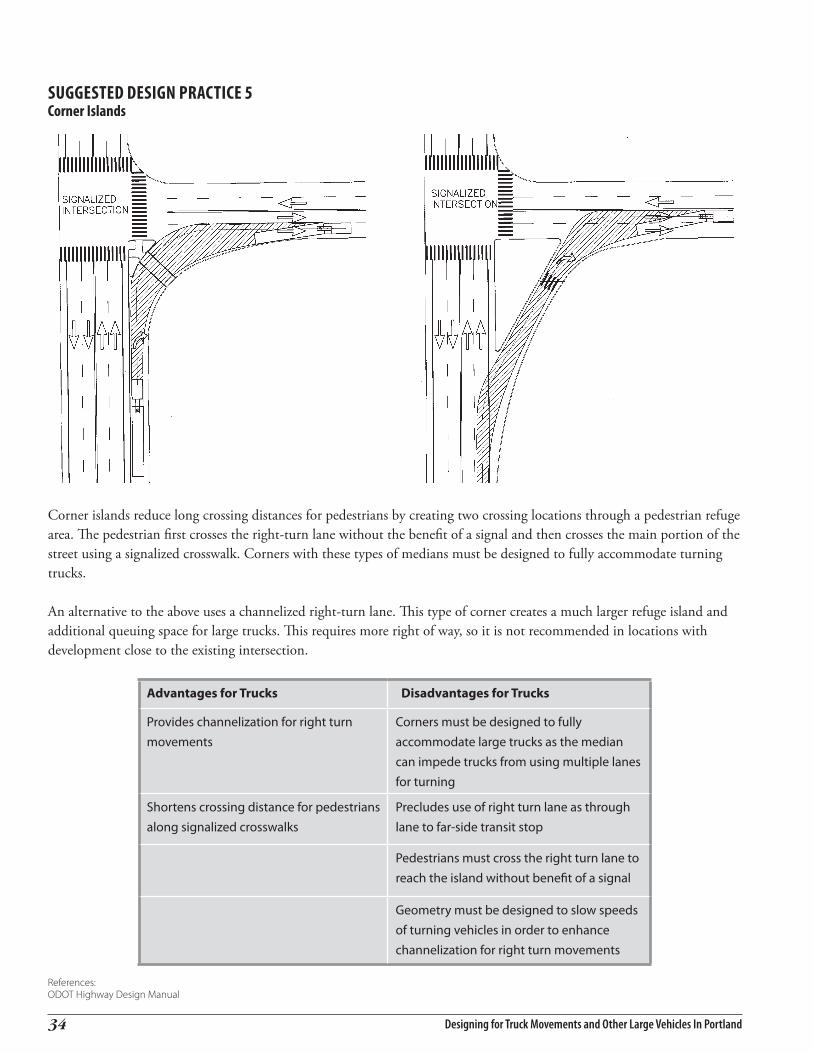
Designing for Truck Movements and Other Large Vehicles In Portland3�
Advantages for Trucks Disadvantages for Trucks
Provides channelization for right turn movements
Corners must be designed to fully accommodate large trucks as the median can impede trucks from using multiple lanes for turning
Shortens crossing distance for pedestrians along signalized crosswalks
Precludes use of right turn lane as through lane to far-side transit stop
Pedestrians must cross the right turn lane to reach the island without benefit of a signal
Geometry must be designed to slow speeds of turning vehicles in order to enhance channelization for right turn movements
References:ODOT Highway Design Manual
suGGested desiGn Practice 5corner islands
Corner islands reduce long crossing distances for pedestrians by creating two crossing locations through a pedestrian refuge area. The pedestrian first crosses the right-turn lane without the benefit of a signal and then crosses the main portion of the street using a signalized crosswalk. Corners with these types of medians must be designed to fully accommodate turning trucks.
An alternative to the above uses a channelized right-turn lane. This type of corner creates a much larger refuge island and additional queuing space for large trucks. This requires more right of way, so it is not recommended in locations with development close to the existing intersection.

Designing for Truck Movements and Other Large Vehicles in Portland ��
When trucks turn they create a shape that can be more closely approximated by use of a corner design with two or three centered curves. This reduces the overall pedestrian crossing distances and required right-of-way over a more traditional single radius corner.
suGGested desiGn Practice 6multiple centered curbs/corners
Advantages for Trucks Disadvantages for Trucks
Intersection corner shape closely matches the shape of the truck for optimum design
Depending on intersection geometry, can be more difficult to engineer and construct
Shortens pedestrian crossing distance compared to a single radius corner designed for the same sized truck
If designed improperly, may result in trucks overrunning the intersection curb and pedestrian waiting area
Reduces right-of-way need over a single curve design
References:AASHTO Guide for the Geometric Design of HighwaysODOT Highway Design Manual

Designing for Truck Movements and Other Large Vehicles In Portland3�
suGGested desiGn Practice 7tapered curbs/corners
Advantages for Trucks Disadvantages for Trucks
Intersection corner shape closely matches the shape of the truck turn movement for optimum design
If designed improperly, may result in trucks overrunning the intersection curb and pedestrian waiting areas
Shortens pedestrian crossing distance compared to a single radius corner designed for the same sized truck
More simplified design and layout than the multiple centered corner
Reduces right-of-way need over a single curve design
References:WSDOT Highway Design Manual
Like the multiple centered corner described in Suggested Design Practice #6, the tapered corner allows the use of a smaller radius curve combined with a 6:1 taper. Like the multiple centered corner, the radius portion of the corner is designed based on the design vehicle for the intersection. The taper is added to better approximate the swept path of the vehicle on the corner exit.

7 case sTuDiescase sTuDies
Designing for Truck Movements and Other Large Vehicles in Portland ��
The following discussion illustrates actual case studies that Office of Transportation designers evaluated and resolved.
Problem and solution i – redirecting Pedestrian movements away from trucksThis case study illustrates a problem that involved a marked pedestrian crosswalk on a busy multi-lane street and the location of a Fred Meyer loading dock that influenced truck maneuvers which impacted pedestrian circulation.
As shown in Figure 9, the location is the intersection of SE Foster Road and SE 80th Avenue. A Fred Meyer store is located on the north side of Foster Road and its loading dock access/egress on SE 80th Ave forced trucks to maneuver through a primary pedestrian path into the store. Further complicating the situation for pedestrians, including passengers walking to and from a bus stop at the northeast corner, was the lack of a crosswalk for pedestrian movements across SE Foster Rd. The traffic control at the intersection is limited to a STOP sign for vehicles entering SE Foster Rd from SE 80th Avenue, and a marked crosswalk with a signed pedestrian crossing symbol for SE Foster Rd traffic.
Initially, a concept solution was developed which created a median pedestrian refuge island (Figure 10) extending to the east side of the intersection. At the site, the designer noted that trucks leaving the Fred Meyer loading dock on SE 80th needed to turn left (eastbound) onto SE Foster Rd for the most direct route to the freeway. When the designer placed truck turning templates over the concept design, it was noted that the sweep area of WB-67 trucks (i.e., the truck type anticipated at the Fred Meyer loading dock) intruded on the median island. In addition, the island did not meet the minimum required width of 10 feet.
The designer then moved the crosswalk and the median island to a mid-block location in order to be out of the path of the truck sweep area (Figure 11) defined by the truck turning template as well as to line up the crosswalk with the main entrance to the Fred Meyer store. A solution was reached with Fred Meyer to provide pavement markings in their parking lot delineating a pedestrian path directly into their main entrance from the realigned mid-block crosswalk provided across SE Foster Rd.A mid-block crossing is typically not a preferred location
figure 9existing condition
SE Foster Rd
SE 8
0th
Ave
Fred Meyers
figure 10initial design solution – add median
figure 11final configuration
SE Foster Rd
SE 8
0th
Ave
Fred Meyers
SE Foster Rd
SE 8
0th
Ave
Fred Meyers

Designing for Truck Movements and Other Large Vehicles In Portland3�
because it may require out of direction travel for pedestrians. In this case, with the addition of the path to the front door of Fred Meyer, the mid-block crossing works for both pedestrians and for trucks turning onto Foster Rd.
Problem and solution ii – long Pedestrian crossing with skewed intersectionThe following case study illustrate a problem designers evaluated and resolved involving intersections on Sandy Blvd through Northeast Portland.
As shown in Figure 12, Sandy Blvd crosses the street grid at a significant skew, creating a number of intersections where the pedestrian crossing distances are very long. Additionally, the angle of intersecting side streets encourages vehicles to make right turns at higher speeds.
Initially, a solution was developed using curb extensions to square up the intersection with the side street (Figure 13). While this solution solved the high speed turn and pedestrian crossing distance issues, it created a tight reverse curve situation that would be difficult for trucks to negotiate.
The design was revised from the concept using an island to improve truck movements (Figure 14). A narrow stretch of the existing pavement was left in place so that trucks could avoid the reverse curve condition when making a right turn.
By adding the island to the intersection, an appearance of a more constrained intersection was created. This encourages a reduced speed for vehicles making the turns. The pedestrian crossing was reduced significantly from the existing condition into two much shorter crossings, enhancing overall pedestrian safety while also accommodating truck movements.
figure 12existing condition
figure 13initial design solution – curb extension
figure 14final design
NE Davis St
NE Sandy Blvd
NE 1
5th A
ve
NE 1
6th A
ve
NE Davis St
NE Sandy Blvd
NE 1
5th A
ve
NE 1
6th A
ve
NE Davis St
NE Sandy Blvd
NE 1
5th A
ve
NE 1
6th A
ve

Designing for Truck Movements and Other Large Vehicles in Portland ��
Problem and solution iii – north Pearl district safeway truck loading activitiesThe third case study examines a proposal to locate a Safeway supermarket in the Pearl District, a dense urban environment in the Central City area. This area is within a “pedestrian district” described in the Pedestrian Master Plan as “compact walkable areas of intense pedestrian use with a dense mix of land uses and good transit service, where walking is intended to be the primary mode for trips within the district.” This area is in the midst of a transition from its historic industrial use to a more mixed-use (housing, retail, office, etc.) environment.
The proposed Safeway development site occupies an entire city block on the northeast corner of NW 14th Avenue and NW Lovejoy Street. The building design placed the loading bay for truck deliveries on NW 14th Avenue, which is classified as a City Bikeway and a Pedestrian District street in the City’s Transportation System Plan. The multiple demands for delivery trucks, pedestrians, cyclists and on-street parking in this dense urban setting posed a significant challenge in designing for necessary truck maneuvering.
In evaluating the multiple demands of this street, PDOT staff considered the following:
• What size trucks will be dominant? • What days/times will truck loading activities occur? • Does the applicant have control over what types of trucks
deliver to the site?• Are supplemental on-street loading spaces needed based on
frequency of deliveries?
Based on initial analysis, staff determined the street would be appropriate for loading and the site could be designed to meet the numerous objectives despite constraints within the right-of-way. The primary concerns in accommodating delivery truck access were potential conflicts with the demands from other vehicles in the travel lanes, cyclists in the bike lane, pedestrians on the sidewalk and parking vehicles.
The loading bay was designed to eliminate encroachment into the nearest intersection by maneuvering delivery trucks and minimize risks related to “blind backing” due to the angle of the loading bay. As shown in Figure 15, the depth of the loading bay was designed to ensure that a parked WB-65
Source: Kittleson & Associates, Inc.
figure 15sidewalk clearance at loading bay

Designing for Truck Movements and Other Large Vehicles In Portland�0
tractor trailer would not restrict the minimum Through Pedestrian Zone 5 which is 8-feet for Pedestrian District streets. Other factors contributing to loading bay design included the need for on-street parking removal and the configuration of the driveway.
A turning maneuver analysis was also conducted to determine the ability for delivery trucks to access southbound NW 16th Avenue upon leaving the proposed Safeway loading bay on NW 14th Avenue. Figure 16 shows a WB-65 tractor trailer exiting the loading bay and accessing NW 16th Avenue via NW Northrup Street. The figure shows that trucks may have difficulty clearing vehicles parked on-street closest to the street corners. In this situation, the city may consider removing on-street parking spaces to accommodate these maneuvers. The city may also consider limiting the construction of curb extensions at these locations with future redevelopment in the area to ensure that truck maneuvering continues to be accommodated.
5 Through Pedestrian Zone is a linear portion of the Sidewalk Corridor which contains no obstructions, openings, or other impediments that would prevent or discourage movement by pedestrians. See Portland Pedestrian Design Guide for more detail.
figure 16truck route to nW 16th avenue
Source: Kittleson & Associates, Inc.

Appendix AAppendix A
Designing for Truck Movements and Other Large Vehicles in Portland A-1
Federal and State Freight routeS, ClaSSiFiCationS, and deSign requirementSdeFinitionSPortland’s functional classification system for its arterial, collector and local streets is based on the City’s Comprehensive Plan. These functional descriptions are intended to meet the needs of land uses and access to and from state and federal highway systems. Arterial streets provide for higher speed through movements and access to the regional highway systems, while collector streets are the major streets, operating at slower speeds than arterials, for accessing neighborhoods, districts, and connections to the arterial street system. Local streets provide immediate access to residential areas and neighborhood commercial districts, and are a subset of the collector street system.
In general, the Portland street system serves as the local routes to and from the state and federal road systems, however, in some cases, Portland streets also have a function in the federal road system. In addition, several State owned and operated highways traverse the City of Portland. Some of these highways include freeways such as I-5 and I-405 and urban arterials such as Powell Blvd, Lombard Street (US 30 Bypass), and 82nd Ave. The Oregon Highway Design Manual and other applicable ODOT guidelines apply to all State highways.
a. Federal highway SystemThe federal highway system is intended to provide high-speed, limited access mobility between regions of the nation, as well as within regions. Their primary initial functions were to provide for interstate commerce and national defense, and while they still serve those purposes, in many areas of the country, including Portland, the federal system also functions as a regional arterial system. Most often they are denoted by the prefix “I” (for interstate, as in I-5) or “US” (as in US 26); but they are also frequently known by their local names (e.g. Powell Blvd on the east side is more commonly used than its federal designation of US 26).
Best known for the interstate highway system, the federal system also includes many other designations, five of which are described below:
• SurfaceTransportationAssistanceAct(STAA) was the federal comprehensive transportation funding and policy act of 1982, which spelled out new rules pertaining to truck size and weight. With respect to truck movement, it established that trucks could weigh as much as 80,000 lbs (gross vehicle weight) and be as long as 70’ without a special permit when traveling on the federal-aid highway system (interstates and other federal roads); except where states had established different weight and length limits. Oregon is one of the states where its 105,000 lb weight limit had been grandfathered.
• TheNationalHighwaySystem is a network of nationally significant roads approved by Congress as required by the Intermodal Surface Transportation Efficiency Act (ISTEA) of 1991. It includes the Interstate system, the Strategic Highway Network (STRAHNET), and over 100,000 miles of arterial and other roads nationwide. Designation of the original system was completed on November 28, 1995, when President Clinton signed the National Highway System Designation Act of 1995 (Public Law 104-59). Intermodal Connectors were added to the system in 1998 when Congress approved the Transportation Equity Act for the 21st Century (TEA-21).

Designing for Truck Movements and Other Large Vehicles In PortlandA-2
• NHSIntermodalConnectors are NHS roads that provide service to major intermodal terminals. Section 101 of the National Highway System Designation Act of 1995 required the Secretary of Transportation to submit NHS Intermodal Connectors to Congress for approval. Congress approved the Intermodal Connectors in 1998 with the passage of the Transportation Equity Act for the 21st Century (TEA-21).
• NationalNetwork provides a safe and efficient highway system for large vehicles that are authorized by the Surface Transportation Assistance Act of 1982. It includes the interstate highway system and other qualifying Federal-aid Primary System Highways. Functional criteria for the national network routes includes: serves to links principal cities high volume route used extensively by large vehicles for interstate commerce, and does not contain any restrictions to conventional combination vehicles.
• Non-StateNHSandNon-StateNN routes are not part of the state highway system, but are part of the national highway system and/or National Network. As shown in Table A.1, City streets such as Columbia Blvd and
Lombard St are part of the National Highway System.
• NHSIntermodalConnectors are the public roads leading to major intermodal terminals. Table A.1 lists the City streets that are designated national highway system intermodal connectors.
• NHSIntermodalFacilities are the region’s primary airports, rail, marine, pipeline and truck terminals (as well as public transit facilities). To be designated a NHS intermodal facility, facilities must serve a relatively high volume of traffic and modes as described in the ISTERA funding act (see http://www.tfhrc.gov/pubrds/may98/nhs.htm).
B. State route designationsThe state highway system includes the federal highway system as well as the state highway system (using the prefix “OR”, such as OR 99E), and is intended to provide for high-speed access between Oregon cities and regions, and the federal highway system. ODOT’s Highway Classification consists of the interstate and state highway systems that are also part of the National Highway System, as well as regional highways which provide inter-regional access (e.g., OR 217), and District Highways which function as collectors for county systems (such as OR 224).
The Oregon Highway Plan 6 describes the state highway functional classification as follows:• InterstateHighways(NHS) provide connections to major cities, regions of the state, and other states. A secondary
function in urban areas is to provide connections for regional trips within the metropolitan area. The Interstate Highways are major freight routes and their objective is to provide mobility. The management objective is to provide for safe and efficient high-speed continuous-flow operation in urban and rural areas.
• StatewideHighways (NHS) typically provide inter-urban and inter-regional mobility and provide connections to larger urban areas, ports, and major recreation areas that are not directly served by Interstate Highways. A secondary function is to provide connections for intra-urban and intra-regional trips. The management objective is to provide safe and efficient, high-speed, continuous-flow operation. In constrained and urban areas, interruptions to flow should be minimal. Inside Special Transportation Areas (STAs), local access may also be a priority.
6 1999 Oregon Highway Plan: Policy Element, Policy 1A, Oregon Department of Transportation, Statewide Highway Classification System, pages 41-42, http://www.oregon.gov/ODOT/TD/TP/docs/orhwyplan/hwyplan/PolicyElement.pdf

Designing for Truck Movements and Other Large Vehicles in Portland A-3
• RegionalHighways typically provide connections and links to regional centers, Statewide or interstate Highways, or economic or activity centers of regional significance. The management objective is to provide safe and efficient, high-speed, continuous-flow operation in rural areas and moderate to high-speed operations in urban and urbanizing areas. A secondary function is to serve land uses in the vicinity of these highways. Inside STAs, local access is also a priority. Inside Urban Business Areas, mobility is balanced with local access.
• DistrictHighways are facilities of county-wide significance and function largely as county and city arterials or collectors. They provide connections and links between small urbanized areas, rural centers and urban hubs, and also serve local access and traffic. The management objective is to provide for safe and efficient, moderate to high-speed continuous-flow operation in rural areas reflecting the surrounding environment and moderate to low-speed operation in urban and urbanizing areas for traffic flow and for pedestrian and bicycle movements. Inside STAs, local access is a priority. Inside Urban Business Areas, mobility is balanced with local access.”
routesAs shown in Table A.1 and illustrated in Figures A.1 through A.6, many Portland streets are also designated on the federal and state highway systems identified above.

Designing for Truck Movements and Other Large Vehicles In PortlandA-4
table a.1 nhS and nn routes in City of Portland
NHS NN Non-StateNHS
Non-StateNN
NHSConnector
Powell Blvd, east of I-405 X
I-5 X X
I-205 X X
I-405 X X
I-84 X X
US 26, west of I-405 X X
US 26 (Powell Blvd), east of I-405 X
US 30 X X
OR 99W X X
OR 99E, I-5 Columbia X X X
OR 99E, south of US 26 X X
OR 99E, Columbia- US 26 X
St Johns Bridge X X
Portland Rd, Columbia–Marine Dr X X
N Marine Dr, N Portland Rd-I-5 X X
N Columbia Blvd, I-205–N Lombard X X
N Lombard, St Johns Br–N Marine Dr X X
NW Front Ave, NW Nicolai–NW 61st X X
N Going St, N Bason–I-5 X
N Greeley St, I-405–N Killingsworth X X
N Killingsworth, N Greeley–N Interstate X X
OR 213 (82nd), NE Columbia–NE Airport Way X X
NE Airport Way, I-205–PDX Terminal X X
NE Cornfoot, NE 47th–NE Alderwood X X
NE Airtrans Rd, NE Cornfoot-PDX Air Freight X
NE Alderwood, NE Cornfoot–OR 213 (82nd) X X
N Interstate, I-405–NE Broadway X X
N Larrabee, N Interstate–Broadway X X
Broadway, NE Broadway–NW Everett X X
NW Glisan, I-405–NW 6th X X
NW Everett, I-405–NW 6th X X
NW 6th, NW Everett–NW Johnson X X
W Burnside, NW Broadway–I-405 X
SE Holgate, OR 99E–UP Brooklyn YD X X
NE 47th, Columbia-Cornfoot X X

Designing for Truck Movements and Other Large Vehicles in Portland A-5
Figure a.1 nhS intermodal FaCilitieS and ConneCtorS in n & nW Portland
Source: www.oregon.gov/ODOT/TD/TDATA/rics/NationalHighwaySystems.shtml
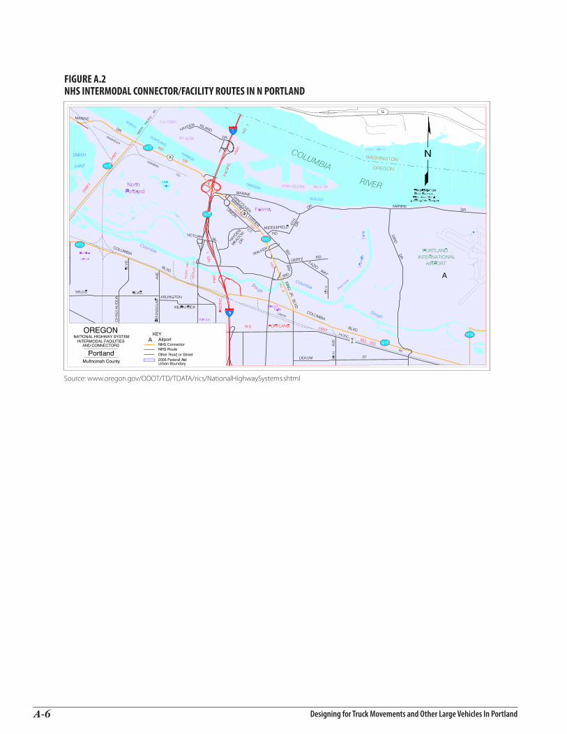
Designing for Truck Movements and Other Large Vehicles In PortlandA-6
Figure a.2 nhS intermodal ConneCtor/FaCilitY routeS in n Portland
Source: www.oregon.gov/ODOT/TD/TDATA/rics/NationalHighwaySystems.shtml

Designing for Truck Movements and Other Large Vehicles in Portland A-7
Figure a.3 nhS intermodal ConneCtor/FaCilitY routeS in nW & ne Portland
Source: www.oregon.gov/ODOT/TD/TDATA/rics/NationalHighwaySystems.shtml

Designing for Truck Movements and Other Large Vehicles In PortlandA-8
Figure a.4 nhS intermodal ConneCtor/FaCilitY routeS in Center CitY
Source: www.oregon.gov/ODOT/TD/TDATA/rics/NationalHighwaySystems.shtml

Designing for Truck Movements and Other Large Vehicles in Portland A-9
Figure a.5 nhS intermodal FaCilitieS and ConneCtorS in ColumBia Corridor
Source: www.oregon.gov/ODOT/TD/TDATA/rics/NationalHighwaySystems.shtml

Designing for Truck Movements and Other Large Vehicles In PortlandA-10
Figure a.6 nhS intermodal ConneCtor/FaCilitY routeS in Se Portland
Source: www.oregon.gov/ODOT/TD/TDATA/rics/NationalHighwaySystems.shtml

Designing for Truck Movements and Other Large Vehicles in Portland A-11
discussion about Function of the different route types, and their respective design requirements * When a city street is designated on the federal and/or state highway network it must meet the design criteria of the federal and state policies and laws governing them. In every case, the reference for design is AASHTO, with some specific consideration listed below:
With respect to routes on the National Network, the following criteria must be met:
“Route must have adequate geometrics to support safe operations, considering sight distance, severity and length of grades, pavement width, horizontal curvature, shoulder width, bridge clearances and load limits, traffic volumes and vehicle mix, and intersection geometry.”
The National Highway System similarly requires adherence to AASHTO, and provides the following reinforcement to national highway policy in this excerpt:
(a) IN GENERAL- The Secretary shall ensure that the plans and specifications for each proposed highway project under this chapter provide for a facility that will:(1) adequately serve the existing and planned future traffic of the highway in a manner that is conducive to safety, durability, and economy of maintenance; and(2) be designed and constructed in accordance with criteria best suited to accomplish the objectives described in paragraph (1) and to conform to the particular needs of each locality.
(c) DESIGN CRITERIA FOR NATIONAL HIGHWAY SYSTEM-(1) IN GENERAL- A design for new construction, reconstruction, resurfacing (except for maintenance resurfacing), restoration, or rehabilitation of a highway on the National Highway System (other than a highway also on the Interstate System) may take into account, in addition to the criteria described in subsection (a):(A) the constructed and natural environment of the area;(B) the environmental, scenic, aesthetic, historic, community, and preservation impacts of the activity; and(C) access for other modes of transportation.(2) DEVELOPMENT OF CRITERIA- The Secretary, in cooperation with State highway departments, may develop criteria to implement paragraph (1). In developing criteria under this paragraph, the Secretary shall consider the results of the committee process of the American Association of State Highway and Transportation Officials as used in adopting and publishing ‘A Policy on Geometric Design of Highways and Streets’, including comments submitted by interested parties as part of such process. …
* City interpretation of AASHTO Guidelines applies on all city streets including NHS facilities when non-federal funds are being used. ODOT Guidelines apply on NHS facilities when federal funds are used.

Designing for Truck Movements and Other Large Vehicles In PortlandA-12
The Oregon Highway Design Manual identifies the design requirements and relevant criteria for state highway system roads and facilities. For federal facilities, the state system uses federal design guidelines (i.e., AASHTO). In addition, under Chapter 366 of the 2007 Oregon Revised Statutes, the following rules apply in respect to reducing vehicle carrying capacity on state highways:
366.215Creationofstatehighways;reductioninvehicle-carryingcapacity. (1) The Oregon Transportation Commission may select, establish, adopt, lay out, locate, alter, relocate, change and realign primary and secondary state highways.(2) Except as provided in subsection 3 of this section, the commission may not permanently reduce the vehicle-carrying capacity of an identified freight route* when altering, relocating, changing or realigning a state highway unless safety or access considerations require the reduction.(3) A local government, as defined in ORS 174.116, may apply to the commission for an exemption from the prohibition in subsection 2 of this section. The commission shall grant the exemption if it finds that the exemption is in the best interest of the state and that freight movement is not unreasonably impeded by the exemption. [Amended by 1977 c.312 §2; 2003 c.618 §38]
*Identified freight routes on the State Highway system can be found at: http://www.oregon.gov/odot/td/freight/index.shtml

aPPenDix BaPPenDix B
Designing for Truck Movements and Other Large Vehicles in Portland B-�
truck desiGn vehicle characteristics and turninG movement information
figure b.1truck design vehicle characteristics and turning movement information
Design Vehicle Symbol Trailer Wheelbase Overall Length
Minimum Design Turning Radius*
VehicleWidths
(with mirrors)
Minimum Inside
Radius**
Automobile P none 11’ 1`9’ 24’ na 14.4’
Bus City Bus none 25’ 40’ 42’ 9.5’-10.0’ 24.5’
Single Unit Truck SU-30 none 20’ 30’ 42’ 9.0’-9.5’ 28.3’
Intermediate Semi-Trailer WB-40 33’ trailer 40’ 45’ 40’ 9.0’-9.5’ 19.3’
Intermediate Semi-Trailer WB-50 42.5’ trailer 50’ 55’ 45’ 9.5’-10.0’ 17.0’
Interstate Semi-Trailer WB-62 48’ trailer 62’ 68.5’ 45’ 9.5’ 7.9’
Interstate Semi-Trailer WB-67 53’ trailer 65’ 73.5’ 45’ 9.5’ 4.4’
Source: The information represented in this table was compiled from various sections of “AASHTO A Policy on Geometric Design of Highways and Streets, 2001, Fourth Edition”.
* Refer to Exhibits 2.3 through 2.23 (pages 21-41) of AASHTO for more complete information on turning radius for various design vehicles.
**For a 180-degree turn.

Designing for Truck Movements and Other Large Vehicles In PortlandB-�

aPPenDix caPPenDix c
Designing for Truck Movements and Other Large Vehicles in Portland C-�
roadWay desiGn lane Width The AASHTO guidance on lane widths is summarized in Table C-1. Summarizing the guidance on lane widths from AASHTO– Geometric Design of Highways and Streets, 2001 is complicated by the fact that the words used for guidance for different types of facilities are not exactly parallel. The words used in the column headings of Table C-1 are taken from the different sections of AASHTO.
table c.1summary of aashto Guidance on lane Width
Preferably Where Practical Generally
Allowable with Severe Limitations
Used Extensively
and Generally Adequate
Most Desirable
Local in Residential Area
> 10’ 11’ – 9’ – –
Local in Industrial Areas
12’ – – 11’ – –
Urban Collector in ResidentialAreas
– – 10’ to 12’ – – –
Urban Collector in IndustrialAreas
12’ – 10’ to 12’ 11’ – –
Urban Arterials – – 10’ to 12’ 10’ with little or
no truck traffic 11’* 12’*
* The discussion of urban arterials in AASHTO also includes the sentence “If substantial truck traffic is anticipated, additional lane with may be desirable.”
Source: AASHTO – Geometric Design of Highways and Streets, 2001For local streets, see page 397For urban collectors, see page 437For urban arterials, see page 476

Designing for Truck Movements and Other Large Vehicles In PortlandC-�
Grade The grade used for a street also varies according to its classification. Streets of higher classification generally have higher traffic volumes and usually higher volumes of truck traffic. These factors influence the desirable and minimum grades.
The AASHTO guidance on grades is summarized in Table C-2. AASHTO’s guidance on grades depends on street classification, and for the higher classifications, on the design speed of the facilities and the terrain.
table c.2summary of aashto Guidance on Grades
Preferred Desirable Desirable (Maximum)
Local Residential Street As level as practical, consistent with surrounding terrain.
>15 percent
Local Streets in Industrial/ Commercial Areas
As level as practical, consistent with surrounding terrain.
>5 percent >8 percent
Collector Streets As level as practical, consistent with surrounding terrain.
For 30 mph:9% for level terrin;11% for rolling:12% for mountainous
Arterial Streets As level as practical, consistent with surrounding terrain.
For 35 and 40 mph:9% for level terrain;11% for rolling:12% for mountainous
Source: AASHTO – Geometric Design of Highways and Streets, 2001For local streets, see page 395For urban collectors, see page 435-6For urban arterials, see page 475

Designing for Truck Movements and Other Large Vehicles in Portland C-�
horizontal clearance to obstructionsThe AASHTO guidance on horizontal clearance to obstructions lane width is summarized in Table C-3.
vertical clearance
The AASHTO guidance on vertical clearance to is summarized in Table C-4.
Recommended Explanation
Local Residential Streets 1.5’ or more from face of curb If practical
Collector Streets 1.5’ or more from face of curb If practical
Arterial streets 1.5’ or more from face of curband
3.0’ clearance particularly near turning radii for intersections and driveways
If practical
Clearance for overhang of trucks
table c.3summary of aashto Guidance on horizontal clearance to obstructions
Source: AASHTO – Geometric Design of Highways and Streets, 2001For local streets, see page 397For urban collectors, see page 441For urban arterials, see page 485
Recommended Explanation
Local Collector Streets 14.0’ Over entire roadway with provision for resurfacing
Arterial Streets 16.5’ Over entire roadway with provision for resurfacing, 14’ may be retained in highly urbanized areas if there is a 16’ alternate route
table c.4summary of aashto Guidance on vertical clearance
Source: AASHTO – Geometric Design of Highways and Streets, 2001For local streets, see page 403For urban collectors, see page 440For urban arterials, see page 476

Designing for Truck Movements and Other Large Vehicles In PortlandC-�
Facilities no Designated as “Oversize Load Routes”
Use the Latest Version of AASHTO
“Oversize Load Routes” 22.0’
table c.5recommended vertical clearance for the city of Portland *
Recommended horizontal clearance to obstructions for use in the City of Portland.
* For vertical clearance associated with bridges, buildings over roadways, and overhead wires.
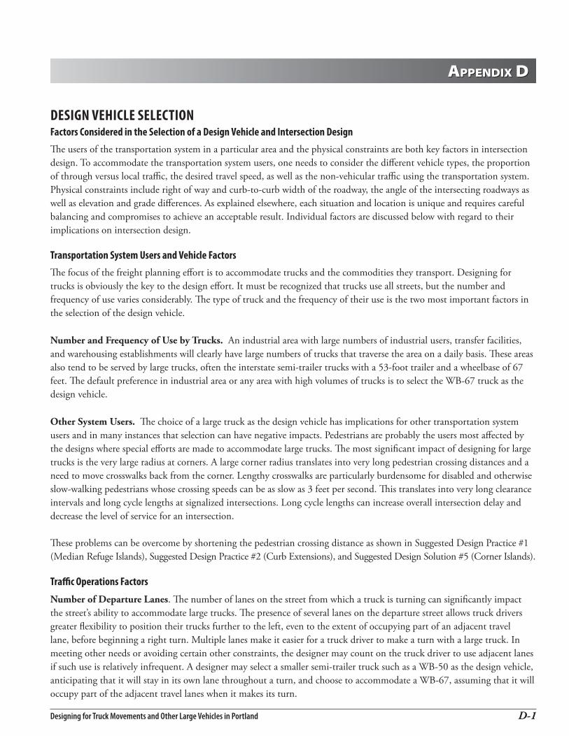
aPPenDix DaPPenDix D
Designing for Truck Movements and Other Large Vehicles in Portland D-�
desiGn vehicle selectionfactors considered in the selection of a design vehicle and intersection designThe users of the transportation system in a particular area and the physical constraints are both key factors in intersection design. To accommodate the transportation system users, one needs to consider the different vehicle types, the proportion of through versus local traffic, the desired travel speed, as well as the non-vehicular traffic using the transportation system. Physical constraints include right of way and curb-to-curb width of the roadway, the angle of the intersecting roadways as well as elevation and grade differences. As explained elsewhere, each situation and location is unique and requires careful balancing and compromises to achieve an acceptable result. Individual factors are discussed below with regard to their implications on intersection design.
transportation system users and vehicle factorsThe focus of the freight planning effort is to accommodate trucks and the commodities they transport. Designing for trucks is obviously the key to the design effort. It must be recognized that trucks use all streets, but the number and frequency of use varies considerably. The type of truck and the frequency of their use is the two most important factors in the selection of the design vehicle.
Number and Frequency of Use by Trucks. An industrial area with large numbers of industrial users, transfer facilities, and warehousing establishments will clearly have large numbers of trucks that traverse the area on a daily basis. These areas also tend to be served by large trucks, often the interstate semi-trailer trucks with a 53-foot trailer and a wheelbase of 67 feet. The default preference in industrial area or any area with high volumes of trucks is to select the WB-67 truck as the design vehicle.
Other System Users. The choice of a large truck as the design vehicle has implications for other transportation system users and in many instances that selection can have negative impacts. Pedestrians are probably the users most affected by the designs where special efforts are made to accommodate large trucks. The most significant impact of designing for large trucks is the very large radius at corners. A large corner radius translates into very long pedestrian crossing distances and a need to move crosswalks back from the corner. Lengthy crosswalks are particularly burdensome for disabled and otherwise slow-walking pedestrians whose crossing speeds can be as slow as 3 feet per second. This translates into very long clearance intervals and long cycle lengths at signalized intersections. Long cycle lengths can increase overall intersection delay and decrease the level of service for an intersection.
These problems can be overcome by shortening the pedestrian crossing distance as shown in Suggested Design Practice #1 (Median Refuge Islands), Suggested Design Practice #2 (Curb Extensions), and Suggested Design Solution #5 (Corner Islands).
traffic operations factors
Number of Departure Lanes. The number of lanes on the street from which a truck is turning can significantly impact the street’s ability to accommodate large trucks. The presence of several lanes on the departure street allows truck drivers greater flexibility to position their trucks further to the left, even to the extent of occupying part of an adjacent travel lane, before beginning a right turn. Multiple lanes make it easier for a truck driver to make a turn with a large truck. In meeting other needs or avoiding certain other constraints, the designer may count on the truck driver to use adjacent lanes if such use is relatively infrequent. A designer may select a smaller semi-trailer truck such as a WB-50 as the design vehicle, anticipating that it will stay in its own lane throughout a turn, and choose to accommodate a WB-67, assuming that it will occupy part of the adjacent travel lanes when it makes its turn.

Designing for Truck Movements and Other Large Vehicles In PortlandD-�
Width of Departure Lanes. The width of the lanes from which a truck is turning also has an impact on the truck driver’s ability to position a truck for turns. Obviously, his flexibility is more limited than with multiple lanes, but wide lanes can increase the ability to accommodate large trucks.
Departure Street Volume. The traffic volume on the street from which a truck is turning can also have an impact on the selection of the design vehicle. Low traffic volumes make it easier for a truck driver to encroach on an adjacent travel lane to make maneuvers.
Departure Street Speed. The operating speed on the street from which a truck is turning can also have an effect on operations and the design selected for an intersection. For most urban streets with speeds of about 35 mph or less, speed makes relatively little difference. Higher speed roads may require the installation of a separate deceleration lane, and/or allowing turning traffic to move from the path of through traffic.
Receiving Lane Width. The width of the lanes of the street onto which a truck is turning also impacts the ability of a truck to negotiate a corner. Like the departure lane width, the receiving lane width allows the truck to move away from the curb during its maneuvers.
Number of Receiving Lanes. The number of lanes on the receiving street may be the single most important factor in accommodating large trucks. Having two or more lanes available to turn into allows a truck driver considerable latitude in moving away from the curb for the completion of a turn. With two or more receiving lanes moving away from the intersection for the truck to turn into, designing for a large WB-67 semi-trailer truck that turns into the far lane allows a smaller curb radius
Receiving Street Speed. The operating speed on the receiving street can be a factor if speeds are high, such as is found in rural settings. If speeds are high, the need for an acceleration lane may influence the design and the number of lanes departing the intersection.
Receiving Street Traffic Volume. Where receiving street traffic volumes are low, the occasional large truck may be able to negotiate a tight corner with narrow streets by intruding into the oncoming traffic lane. A flagger, pilot car, or even permits may be required in some cases. On high volume streets such maneuvers may be so intrusive that they cannot be permitted.
Intersection Traffic Control. An intersection controlled by a traffic signal will have different operating and design considerations from one using either two-way or all-way stop control. A traffic signal assigns the right of way for specific intervals giving each user an opportunity for movements. Two-way stop control puts the burden on the vehicle operator to wait for an appropriate gap in the conflicting traffic streams before making a maneuver. Because trucks are larger and have slower acceleration, the gaps required are substantially greater. Acceleration lanes and wide radii may be required where intersections are stop-controlled.
Large Truck Turning Volumes. The volume of trucks is extremely important in the selection of a design vehicle and the ultimate configuration of an intersection. A tight intersection that is difficult for trucks to negotiate may be acceptable when trucks are infrequent. When high volumes of trucks are a daily occurrence, the preference is to select larger design vehicles and design intersections to make their maneuvers easier. Consider the difference between the occasional moving van negotiating a neighborhood street versus the constant flow of semi-trailer trucks in an industrial area.
Truck Movements by Time of Day. In some cases, high volume truck activity occurs during times when other traffic is low. If truck movements occur primarily during off-peak times, it may be acceptable to assume large trucks will intrude on adjacent travel lanes for their maneuvers. If truck movements are high during peak hours, such interference may not be acceptable and designing for the larger vehicle may be preferable.

Designing for Truck Movements and Other Large Vehicles in Portland D-�
street features and Physical conditions
On-Street Parking. The presence of a lane for on-street parking increases the effective radius of a corner because it allows turning vehicles to start maneuvers further from the curb. An on-street parking lane makes allows large trucks to be accommodated without such large radii for the curb.
On-Street Bicycle Lanes. Like parking lanes, bicycle lanes increase the effective radius of a corner.
Median Curb and Raised Islands. Median curbs and raised islands inhibit the opportunity for large trucks to intrude into other lanes. In general, these features make it more difficult for a designer to accommodate large trucks
Curb Extensions. Curb extensions are used to reduce the pedestrian crossing distances at corners. To create curb extensions, sections of on-street parking lanes nearest the corners are replaced with curbs and wide sidewalks or planting areas. In essence, curb extensions eliminate the increase in effective corner radius associated with on-street parking lanes.
Bus Stops. Bus stops are categorized as either “near-side” or “far-side” stops depending on whether the passenger loading area is placed before or after the intersection. The presence of a bus pull-out, a feature that is relatively uncommon, could have an impact on intersection design, but in most cases, a bus stop would have little effect.
land use/transportation link
Adjacent Zoning/Comprehensive Plan Designation. Because of the strong linkage between land use and the transportation system, and the importance of truck freight to serve industrial and commercial areas, understanding the land uses of a street or an area is extremely important to the selection of the design vehicle for intersections. Selection of a WB-67 interstate semi-trailer truck as a design vehicle is highly desirable for intersections adjacent to major industrial centers and on corridors connecting them to the interstate highway system. In contrast, smaller design vehicles are more appropriate for residential areas where large trucks are rare.
Building Setbacks. Because of all the competing needs at corners, setbacks of existing buildings at corners can have an effect on the ultimate selection of an intersection design. Space between the curb and adjacent buildings is required for traffic signals and related equipment, curb ramps and sidewalks that meet the requirements of the Americans with Disabilities Act, and utilities above and below ground level. Existing buildings in combination with other needs may dictate the curb locations, which in turn force the selection of a smaller design vehicle than would otherwise be desirable.
Observed/Anecdotal Truck Activity. The presence of high levels of truck activity is a clear indicator of a need to design for trucks. Trucks common to the area influence the selection of the design vehicle.
Pedestrian Activity. The presence of high numbers of pedestrians argues for minimizing crossing distances and keeping intersections as small as possible. Not only does this reduce the pedestrians’ exposure, it reduces the pedestrian crossing interval and the cycle length. Short pedestrian intervals and cycle lengths help to reduce overall delay at intersections. Designing for turning movements by large trucks is a significant conflict in locations with high pedestrian activity.
Bus Routes. The presence of bus routes can have benefits while also introducing conflicts. Intersections designed for large trucks are beneficial since both trucks and buses need larger turning radii than do automobiles. Bus routes also correspond with higher pedestrian activity, which causes conflicts for the reasons discussed above.
Emergency Response Routes. The needs associated with emergency response routes are generally consistent with streets and intersections designed for large trucks.

Designing for Truck Movements and Other Large Vehicles In PortlandD-�
Availability of Alternative Routes for Large Trucks. Though multiple routes are generally desirable, the existence of readily available alternative routes can be justification for selecting a smaller design vehicle or choosing to accommodate, rather than to design for, large trucks.
Over-Dimension Route. The need for an over-dimension route is clearly consistent with designing for the largest legal loads.
existing conditions
Tire Tracks on Curb or Sidewalk. Tire tracks visible on the curb and sidewalk are clear evidence that trucks are unable to negotiate the existing configuration of a corner. Such evidence suggests that such intersections were not designed with appropriate design vehicles in mind.
Infrastructure and Private Property Damage by Trucks. Knock-downs of pedestrian signal heads and traffic signs due to truck turning is a more common occurrence than one might expect. These are also a clear indication that the intersections were not designed for the appropriate size of trucks.