Embed Size (px)
Citation preview

2017 International Conference on Energy, Power and Environmental Engineering (ICEPEE 2017)
ISBN: 978-1-60595-456-1
Designing of PMU Tester in Smart Substation Based on Test Method
Li HE, Yu-fei TENG, Shi-lin FENG, Zhen-chao JIANG and Ming-zhong LIU
State Grid Sichuan Electric Power Research Institute
Keywords: PMU; Smart substation; Distribution characteristics; Test method; PMU tester.
Abstract. It lacks the effective ways to test the PMU in smart substation at present. The testing
method based on distribution characteristics of acquisition unit and concentration unit of PMU in
smart substations, is proposed to solve the situation of PMU of smart substation. Therefore, the
PMU tester belonging to smart substation is designed based on the fundamental requirements of
tester according to the methods proposed, and the vital points of designing are introduced and
emphasized to tackle the reliability of PMU. The method and technology raised and the PMU tester
designed in smart substation, in practical, could complete the test of accuracy of PMU, abbreviate
the procedure of complicated data disposal and test report composing. It ensures to ameliorate the
testing efficiency and validity on PMU of smart substation.
Introduction
PMU, based on the same time scale among the substations, could be used to measure the
amplitude and phase angle of voltages and currents, active powers and reactive powers. It is widely
applied in the area of WAMS application, state estimation, relay protection, area stability control,
system analysis and estimation, etc. [1-2]
. Thus, it is an essential device for security and stability of
power systems [3-4]
.
PMU uses highly precise clock synchronization to monitor, protect and control the power
systems based on the platform of dispatching and controlling by methods of transferring data to
dispatching and controlling center [5-6]
. However, traditional ways have already failed to meet the
needs of PMU testing in smart substation as the rapid evolution of smart substation is putting
forward [7-10]
. Therefore, it is necessary to raise modifications, and to develop new devices to test
the relative function of PMU [11]
. The precision testing of PMU, among these testing items, is the
most important [12-13]
. In practice, lots of verbose and unmanageable tests concern about precisions
of static and dynamic responses, which demand laborious work without guarantees of minimized
errors and maximum correctness [14]
.
According to reference [14] proposed recently, focusing on the installation characteristics of
PMU in smart substation, a new approach has been raised to test PMU. A new PMU tester in smart
substation according to this new approach has also been developed. The tester, which integrates
optional items of testing, could play a key role of close testing loop. The close loop could
implement the testing of static and dynamic response precision of PMU quickly. Eventually, the
tester automatically generates the testing report according the testing process.
Test Method of PMU
While acquisition unit of PMU is distant from concentration unit of the device, it is not achievable
to exert a PC client receiving the data from concentration unit of PMU by using only one network
cable. Thus, two PC clients should be applied to test the PMU, among one of which sends data to
acquisition unit of PMU, the other receives data from concentration unit of PMU. From there, each
PC clients could generate the data documents labeled time. Finally, the data documents are imported
to tester software for processing and testing reports would be generated automatically. Figure 1
shows the detail principle of connections on PMU testing.
296

PC client 1
PMU testerAcquisition
unit of PMU
Concentration
unit of PMU
Time
synchronic
device
Network cable
Optical fiber
Optical fiber
Opical fiber
Optical fiber
Optical fiber
PC client 2
Optical fiberNetwork cable
Figure 1. Test schematic of PMU.
Derived from figure 1, the close loop testing method is suitable for special condition of
installation of PMU. The testing method could be implemented by 2 PC clients, one sends PMU
data to acquisition unit and the other receives data from concentration unit of PMU.
Design of PMU tester
Analysis of Function on PMU Tester
As mentioned above, the effects of PMU tester are functioned with three aspects: to send data to
acquisition unit of PMU, to receive data from concentration unit of PMU, and to deal with data and
automatically generates report. In this section we shall elaborate analysis of function needs about
PMU tester incorporate with the test methods.
The PMU tester should be set up with data sending module, which simulates merge unit to send
time labeled data to acquisition unit of PMU by optical port.
Data receiving module, which accepts the time labeled data from concentration unit of PMU by
cable, should be set up within the PMU tester. The tester software should simultaneously analyze
the data and implement the job of comparison.
GPS module should receive the accurate time label correctly, as well as synchronize between the
PMU acquisition unit and concentration unit.
The software of PMU tester should work on comparison between sending data and receiving data
then generates the report. The sending data and receiving data are generated by PC client
respectively, so they should be imported in software to be processed. The test report is further
generated based on the results of calculation.
Hardware Structure of PMU Tester
Major components of the PMU tester: ARM, DSP, DSP and synchronic circuits. The hardware
structure is shown by figure 2.
PC client ARM & DSP
FPGA
Unit of data
processing
distribution & fiber
port distribution
8 fiber port
6 FT3 fiber ports
acquisition unit of
PMU
Synchronic circuit
concentration unit
of PMU
PMU tester
switch value
Figure 2. Hardware structure of PMU tester on smart substation.
Shown in figure 2, ARM plays a role in communication with PC clients in order to receive the
commands from the PMU tester and to send the sample value and GOOSE. Order received from
ARM is transferred to DSP, which produces the typical digital signal of power systems. The FPGA
receives data and orders from DSP through address bus, data bus and controlling signal. The data,
297
which obeys IEC61850-9-2 protocol with accurate time labeling, is sent to acquisition unit of
pending PMU through the optical fiber.
The data received from PMU tester is transformed into the format of PMU2.0 [15]
and return back
to PMU tester after the packing and gathering processes in concentration unit of PMU. The
comparison and analysis of loopback data between sending data marked with time label are drawn
by software calculation.
Software Structure of PMU Tester
The Windows XP platform is embedded as interface of the PMU tester. The interface of PMU tester,
which administrates the whole function of tester, has advantages of facility and user friendliness.
The user of PMU tester could integrate the items of PMU testing in the software of PMU tester and
setup the standard of testing tolerances.
The PMU tester is designed and developed by the idea presented in figure 3 according to actual
condition of smart substation and close loop of testing principle on PMU in previous sections.
configurate the PMU
tester in PC client
In span of t1+△t,PC client 1
sends IEC61850-9-2 data
PC client 2 analyze the
absolute time and testing
phasor
Store the data as the
phasor format of
△t→V(I)
both files are imported in
PC client, calculate the
error according to the time
mark and value
generate the report based
on the test and
calculation.
start
end
PC client 2 receive data
from concentration unit of
PMU
Test complete?
Generate the sending file in PC client 1,
while generate the receiving file in PC
client 2. both files are produced with
time mark.
Force t1=t1+△t
yes
no
Figure 3. Flow chart of PMU tester on smart substation.
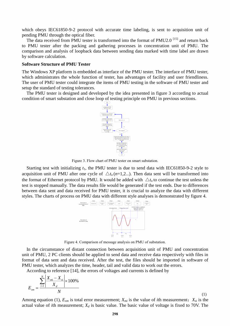
Starting test with initializing t1, the PMU tester is due to send data with IEC61850-9-2 style to
acquisition unit of PMU after one cycle of △tn (n=1,2…). Then data sent will be transformed into
the format of Ethernet protocol by PMU. It would be added with △tn to continue the test unless the
test is stopped manually. The data results file would be generated if the test ends. Due to differences
between data sent and data received for PMU tester, it is crucial to analyze the data with different
styles. The charts of process on PMU data with different style analyses is demonstrated by figure 4.
Sychronic frameThe number of
frame
ID of concentration
unit of PMUsecond
Quality of time
scaledata
16 bit check of
CRC
△t1△t2
Absolute
time t1
Absolute
time t2
Absolute
time t3
The format of
IEC61850-9-2 data
The format of
concentration unit of
PMU
include frequency, amplitude,
angle and variation of
frequency and so on
start point of test Point of first cycle
…
2 byte 2 byte 8 byte 4 byte 4 byte 14 byte 2 byte
Figure 4. Comparison of message analysis on PMU of substation.
In the circumstance of distant connection between acquisition unit of PMU and concentration
unit of PMU, 2 PC clients should be applied to send data and receive data respectively with files in
format of data sent and data received. After the test, the files should be imported in software of
PMU tester, which analyzes the time, header, tail and valid data to work out the errors.
According to reference [14], the errors of voltages and currents is defined by
1
100%N
mi si
i d
xm
X X
XE
N
(1)
Among equation (1), Exm is total error measurement; Xmi is the value of ith measurement;Xsi is the
actual value of ith measurement; Xd is basic value. The basic value of voltage is fixed to 70V. The
298

basic value of currents is 1.2A while the rated value of secondary side of current transformer is 1A.
Similarly, the basic value of currents is 6A while the rated value of secondary side of current
transformer is 5A. The basic value of power is defined as 3 times of multiplication of basic value of
voltage and basic value of current.
The definition of angle, frequency and change rate of frequency is demonstrated by
1
N
mi si
im
Y Y
EN
(2)
Exm is error of measurement; Ymi is ith value of measurement; Ysi is ith actual value of measurement;
N means times of measurement.
The test report is obtained by test and calculation with Word 2007, which includes basic
information of PMU, environment of test and results of test.
In conclusion, based on the method and PMU tester developed, the test steps of PMU in smart
substation are listed below:
Step 1: implement the close loop connection according to the test principle of chart.
Step 2: import the SCD file of smart substation to the PMU tester.
Step 3: set up the input/output configuration and component message based on SCD file of smart
substation.
Step 4: connect the PMU and PMU tester, complete the items of PMU tester.
Step 5: click the start button to test the PMU automatically and finish the process, then generate
the test report automatically.
Analysis of Test Case
Background of Test
The PMU tester has been applied to a 500kV smart substation of 2/3 style. There are 2 transformers
and 4 line outlets in the smart substation.
Test on Part 500kV of Smart Substation
Take an example of a 500kV line to elaborate the static and dynamic response error of voltage and
current. According to section 1.2, 2 PC clients are used in data sending and receiving.
Set up the standard of measurements on static and dynamic test as Un is rated voltage, In is rated
current. The test results as sub values demonstrated here below are only listed in the form of typical
currents and voltage (static test) and amplitude modulation (dynamic test).
Table 1. Test results of static current and voltage on 500kV line of smart substation.
Items sub-items standards results errors
Ua (V)
10%Un 10%In 5.7735 5.7723 0.0017
50%Un 50%In 28.8675 28.8667 0.0011
100%Un 100%In 57.7350 57.7334 0.0023
Angle of Ua (°)
10%Un 10%In 0.0000 -0.0286 0.0286
50%Un 50%In 0.0000 -0.0286 0.0286
100%Un 100%In 0.0000 -0.0286 0.0286
Ia (A)
10%Un 10%In 0.1000 0.0999 0.0056
50%Un 50%In 0.5000 0.4998 0.0168
100%Un 100%In 1.0000 0.9996 0.0297
Angle of Ia (°)
10%Un 10%In 0.0000 -0.0286 0.0286
50%Un 50%In 0.0000 -0.0286 0.0286
100%Un 100%In 0.0000 -0.0286 0.0286
299

Table 2. Test results of 0.1 amplitudes modulation on 500kV line of smart substation.
items standards results errors
Ua (V) 52.3152 52.3052 0.0145
Ub (V) 63.4630 63.4722 0.0133
Uc (V) 52.7471 52.7365 0.0153
Angle of Ua (°) 0.0000 -0.1776 0.1776
Angle of Ub (°) -120.0000 -120.1722 0.1722
Angle of Uc (°) 120.0000 119.8341 0.1659
fundamental frequency (Hz) 50.0000 50.0000 0.0000
Rate of change on
frequency(Hz/s) 0.0000 -0.0010 0.0010
The test items are passed according to the test results. In fact, the displays of acquisition unit of
PMU about measurement are corresponding to dispatch and control center. In conclusion, the PMU
tests results of smart substation based on the method and the PMU tester are valid and reliable.
Comparison of Test
With same tests items performed in section 3.2, the PMU tester is applied to PMU which is made by
2 manufactures with the same standards mentioned in section 3.2. The test results are given by
Tab.3.
Table 3. The comparison of test results between two PMUs produced by different manufactures.
items standards results of
man.1
results of
man.2
Errors of
man.1 (%)
Errors of
man.2 (%)
Ua (V) 57.7350 57.7334 57.7321 0.0023 0.0041
Angle of Ua (°) 0.0000 -0.0286 0.0308 0.0286 0.0308
Ia (A) 1.0000 0.9996 0.9994 0.0297 0.0500
Angle of Ia (°) 0.0000 -0.0286 0.0290 0.0286 0.0290
0.1Hzmodulation (Ua) (V) 52.3152 52.3052 52.3192 0.0145 0.0057
0.1Hzmodulation (angle of Ua) (°) 0.0000 -0.1776 0.1344 0.1776 0.1344
From the table, the items tested of both manufactures are qualified. The static test accuracy of
manufacture 1 is better than that of manufacture 2 while the dynamic test accuracy of manufacture 2
is better than that of manufacture 1.
By examining test span, data dealing time and report generation, prominent advantages of the
tests based on the method and PMU tester on smart substation are seen. Authentic automation and
intelligence of the test have been achieved from a principal level.
Summary
The essay raises the method that suits for PMU of smart substation according to the characteristics
of PMU. Based on method and function needs, the PMU tester of smart substation is developed and
researched. Introduction of crucial steps in the development have been emphasized. The tests of
voltage and current accurate about the static and dynamic tests could be implemented fast and
correctly. It surely decreases the amount of works on data processing and report writing, and
improves the effectiveness and correctness on the tests of PMU in smart substation.
According to the field tests of PMU on a new 500kV smart substation, the PMU tester is a
powerful, flexible, user-friendly device, which would guarantee reliable operations of smart
substation. The application of PMU tester developed would greatly improve the quality of domestic
wide area measurements, and ensure the security of smart power systems.
300

References
[1] Li Hui, Xu Jianyuan, Liu Fei, et al. Research and application on high performance
synchrophasor measurement unit [J]. Power System Protection and Control, 2010, 38(3):81-83.
[2] Duan Gang, Yan Yaqin, Xie Xiaodong, et al. Development Status Quo and Tendency of Wide
Area Phasor Measuring Technology[J]. Automation of Electric Power Systems, 2015, 39(1):73-80.
[3] Chu Yanhua. Study on Lite Area Synchuronous Monitoring System for Power System [D].
Ji’nan:Shandong University,2012.
[4] Zhang Hengxu, Jin Zongshuai, Liu Yutian. Wide-area Measurement System Light and Its
Application in China [J]. Automation of Electric Power Systems, 2014, 38(22): 85-90.
[5] Xie Xiaolei, Liu Yadong, Sun Peng, et al. Development of Novel PMU Device for Distribution
Network Lines [J]. Automation of Electric Power Systems, 2016, 40(12): 73-80.
[6] M. Zima, M. Larsson, P. Korba, et al. Design Aspects for Wide-Area Monitoring and Control
Systems, Proceedings of the IEEE, 93(5), 2005, 980-996.
[7] Xu Yong, Wang Huizheng, Li Qian, et al. Development of Synchronized Phasor Measurement
Units for Smart Substations [J]. Power System Technology, 2010, 34(11):1-3.
[8] Bi Tianshu, Liu Hao, Yang Qixun. Dynamic Performance of PMU Algorithm and Its Testing
System [J]. Automation of Electric Power Systems, 2014, 38(1): 62-67.
[9] Zhang Daolong, Liu Hao, Bi Tianshu, et al. Comparison of the PMU Static and Dynamic
Standards and Evaluation Methods between Chinese Standards and IEEE [J]. Power System
Protection and Control, 2013, 41(17): 140-145.
[10] Zhang Xiaoli, Zhou Zexin, Zhang Dongnao, et al. Testing and evaluation method of phasor
measurement unit [J]. Journal of Electric Power Science and Technology, 2011, 26(2): 31-33.
[11] Bao Wei, Qiu Yutao, Pan Wulue, et al. Development and Research on PMU Tester Based on
IEC61850 [J]. Electrical Measurement & Instrumentation, 2015, 52(17): 125-128.
[12] IEC61850-7-4 Communication networks and systems for power utility automation: Part 7-4
basic communication structure—compatible logical node classes and data object classes [S]. 2010.
[13] IEEE Standard C3.118.1: 2011, IEEE Standard for Synchrophasors for Power Systems [S].
[14] Li Jingsong, Yan Yaqin, Li Qiang, et al. Q/GDW11202.6-2014 the test specification for
automation equipment in smart substation. Part 6: phasor measurement unit [S]. Beijing: China
Electric Power Press, 2015.
[15] Zhang Daolong, Wang Yingtao, Yu Yuehai, et al. GB/T26865.2-2011 Real-time dynamic
monitoring systems of power system- part 2: protocols for data transferring [S]. Beijing: China
standard press, 2011.
301