Embed Size (px)
DESCRIPTION
ProEngineer surfacing cours
Citation preview

PTC Global Services
DDeessiiggnniinngg WWiitthh SSuurrffaacceessRelease 2001
T868-320-01
Training AgendaDesigning With SurfacesDay 1
Introduction to Surfacing
Initial Surfaces
Geometry for Surfaces: Points and Curves
Manipulating Surfaces
Modifying Solid Surfaces Using Quilts
Day 2
Creating Solids Using Quilts
Boundary Surfaces
Variable Section Sweeps
Swept Blends
Day 3
Surface Information and Analysis
Surfaces Continuities
Additional Advance Surfacing Tools
Working with Imported Surfaces
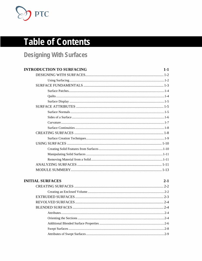
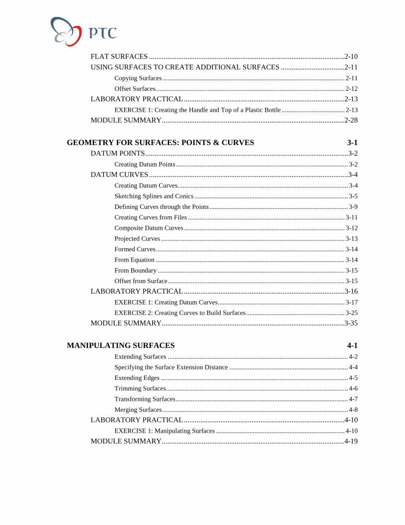
Table of ContentsDesigning With Surfaces
INTRODUCTION TO SURFACING 1-1DESIGNING WITH SURFACES...................................................................................... 1-2
Using Surfacing..................................................................................................................1-2
SURFACE FUNDAMENTALS ........................................................................................ 1-3
Surface Patches...................................................................................................................1-4
Quilts ..................................................................................................................................1-4
Surface Display ..................................................................................................................1-5
SURFACE ATTRIBUTES ................................................................................................ 1-5
Surface Normals .................................................................................................................1-5
Sides of a Surface ...............................................................................................................1-6
Curvature ............................................................................................................................1-7
Surface Continuities ...........................................................................................................1-8
CREATING SURFACES .................................................................................................. 1-8
Surface Creation Techniques..............................................................................................1-9
USING SURFACES ........................................................................................................ 1-10
Creating Solid Features from Surfaces .............................................................................1-10
Manipulating Solid Surfaces ............................................................................................1-11
Removing Material from a Solid ......................................................................................1-11
ANALYZING SURFACES ............................................................................................. 1-11
MODULE SUMMERY.................................................................................................... 1-13
INITIAL SURFACES 2-1CREATING SURFACES .................................................................................................. 2-2
Creating an Enclosed Volume ............................................................................................2-2
EXTRUDED SURFACES ................................................................................................. 2-3
REVOLVED SURFACES ................................................................................................. 2-4
BLENDED SURFACES .................................................................................................... 2-4
Attributes ............................................................................................................................2-4
Orienting the Sections ........................................................................................................2-4
Additional Blended Surface Properties ..............................................................................2-6
Swept Surfaces ...................................................................................................................2-8
Attributes of Swept Surfaces ..............................................................................................2-9
FLAT SURFACES ...........................................................................................................2-10
USING SURFACES TO CREATE ADDITIONAL SURFACES ...................................2-11
Copying Surfaces ............................................................................................................. 2-11
Offset Surfaces................................................................................................................. 2-12
LABORATORY PRACTICAL........................................................................................2-13
EXERCISE 1: Creating the Handle and Top of a Plastic Bottle ...................................... 2-13
MODULE SUMMARY....................................................................................................2-28
GEOMETRY FOR SURFACES: POINTS & CURVES 3-1DATUM POINTS...............................................................................................................3-2
Creating Datum Points ....................................................................................................... 3-2
DATUM CURVES.............................................................................................................3-4
Creating Datum Curves...................................................................................................... 3-4
Sketching Splines and Conics ............................................................................................ 3-5
Defining Curves through the Points ................................................................................... 3-9
Creating Curves from Files .............................................................................................. 3-11
Composite Datum Curves ................................................................................................ 3-12
Projected Curves .............................................................................................................. 3-13
Formed Curves................................................................................................................. 3-14
From Equation ................................................................................................................. 3-14
From Boundary ................................................................................................................ 3-15
Offset from Surface.......................................................................................................... 3-15
LABORATORY PRACTICAL........................................................................................3-16
EXERCISE 1: Creating Datum Curves............................................................................ 3-17
EXERCISE 2: Creating Curves to Build Surfaces........................................................... 3-25
MODULE SUMMARY....................................................................................................3-35
MANIPULATING SURFACES 4-1Extending Surfaces ............................................................................................................ 4-2
Specifying the Surface Extension Distance ....................................................................... 4-4
Extending Edges ................................................................................................................ 4-5
Trimming Surfaces............................................................................................................. 4-6
Transforming Surfaces....................................................................................................... 4-7
Merging Surfaces ............................................................................................................... 4-8
LABORATORY PRACTICAL........................................................................................4-10
EXERCISE 1: Manipulating Surfaces ............................................................................. 4-10
MODULE SUMMARY....................................................................................................4-19

MODIFYING SOLID SURFACES USING QUILTS 5-1USING QUILTS TO MANIPULATE SOLIDS ................................................................ 5-2
REPLACING SURFACES ................................................................................................ 5-2
PATCHING........................................................................................................................ 5-3
USING QUILTS TO CUT SOLIDS .................................................................................. 5-4
LABORATORY PRACTICAL ......................................................................................... 5-5
EXERCISE 1: Creating a Stiffener and a Rib for Fuselage................................................5-6
EXERCISE 2: Creating Cuts Using Surfaces...................................................................5-16
MODULE SUMMARY ................................................................................................... 5-21
CREATING SOLIDS USING QUILTS 6-1USING QUILTS TO GENERATE SOLID FEATURES .................................................. 6-2
Creating a Thin Feature ......................................................................................................6-2
Protruding a Solid Feature..................................................................................................6-2
Combining an Intersecting Quilt ........................................................................................6-3
OFFSETTING SURFACES............................................................................................... 6-4
Offset Methods ...................................................................................................................6-4
LABORATORY PRACTICAL ......................................................................................... 6-9
EXERCISE 1: Creating a Solid Part of a Car Hood.........................................................6-10
EXERCISE 2: Using Offset Surfaces for Shelling...........................................................6-15
MODULE SUMMARY ................................................................................................... 6-20
BOUNDARY SURFACES 7-1CREATING SURFACES USING BOUNDARIES........................................................... 7-2
BLENDED SURFACES .................................................................................................... 7-2
Blended Surface with Approximate Curves .......................................................................7-5
CONIC SURFACES .......................................................................................................... 7-7
N-SIDED SURFACES....................................................................................................... 7-8
RIBBON SURFACES........................................................................................................ 7-8
LABORATORY PRACTICAL ....................................................................................... 7-10
EXERCISE 1: Blending Surfaces.....................................................................................7-11
EXERCISE 2: Changing Blend Control Points................................................................7-29
MODULE SUMMARY ................................................................................................... 7-37
VARIABLE SECTION SWEEP 8-1THE VARIABLE SECTION SWEEP............................................................................... 8-2
Defining Trajectories..........................................................................................................8-2
Specifying Section Orientation...........................................................................................8-2
Adding Control: Using Relations in Variable Section Sweeps ..........................................8-5
Restrictions on Variable Section Sweeps........................................................................... 8-7
LABORATORY PRACTICAL..........................................................................................8-8
EXERCISE 1: Using Variable Section Sweeps to Design the Plastic Bottle..................... 8-9
EXERCISE 2: Creating a Wavy Washer ......................................................................... 8-22
MODULE SUMMARY....................................................................................................8-25
SWEPT BLENDS 9-1INTRODUCTION ..............................................................................................................9-2
Defining the Origin Trajectory........................................................................................... 9-2
Creating Sections ............................................................................................................... 9-2
Additional Controls to Modify the Swept Blend Feature................................................... 9-4
Restrictions on Swept Blends............................................................................................. 9-6
LABORATORY PRACTICAL..........................................................................................9-7
EXERCISE 1: Creating a Manifold ................................................................................... 9-8
MODULE SUMMARY....................................................................................................9-17
SURFACE INFORMATION & ANALYSIS 10-1ANALYZING GEOMETRY............................................................................................10-2
Gaussian Curvature .......................................................................................................... 10-3
Section Curvature............................................................................................................. 10-4
Slope ................................................................................................................................ 10-5
Porcupine ......................................................................................................................... 10-5
Normals............................................................................................................................ 10-6
Draft Check...................................................................................................................... 10-6
Reflection Curves............................................................................................................. 10-6
Radius .............................................................................................................................. 10-7
Offset Mesh...................................................................................................................... 10-7
Deviation.......................................................................................................................... 10-8
Highlight Curves .............................................................................................................. 10-8
Information at a Certain Point.......................................................................................... 10-8
Dihedral Angle................................................................................................................. 10-9
LABORATORY PRACTICAL......................................................................................10-10
EXERCISE 1: Analyzing Surfaces ................................................................................ 10-11
MODULE SUMMARY..................................................................................................10-23
SURFACE CONTINUITIES 11-1THE CURVATURE .........................................................................................................11-2
CONTINUITY BETWEEN GEOMETRIC ENTITIES...................................................11-3
USING CURVATURE CONTINUOUS SURFACES.....................................................11-4

Creating Curvature Continuous Surfaces .........................................................................11-4
Analyzing Curvature Continuous Surfaces ......................................................................11-5
LABORATORY PRACTICAL ....................................................................................... 11-6
EXERCISE 1: Creating Blended Transitions ...................................................................11-7
MODULE SUMMARY ................................................................................................. 11-16
ADDITIONAL ADVANCE SURFACING TOOLS 12-1USING ADDITIONAL SURFACING OPTIONS .......................................................... 12-2
SECTION TO SURFACE................................................................................................ 12-2
TANGENT TO SURFACE.............................................................................................. 12-3
SURFACE TO SURFACE............................................................................................... 12-4
FREE-FORM SURFACE FEATURES ........................................................................... 12-5
Using Freeform.................................................................................................................12-5
Defining Manipulate Options ...........................................................................................12-6
Using Dynamic Diagnostics .............................................................................................12-7
LABORATORY PRACTICAL ....................................................................................... 12-8
EXERCISE 1: Creating Draft Surfaces of a Boss ............................................................12-9
EXERCISE 2: Free Form Manipulation.........................................................................12-14
MODULE SUMMARY ................................................................................................. 12-20
WORKING WITH IMPORTED SURFACES 13-1WORKING WITH IMPORTED SURFACES................................................................. 13-2
Working Method ..............................................................................................................13-3
WORKING WITH PROBLEM SURFACES .................................................................. 13-3
Identifying Problematic Surfaces .....................................................................................13-4
Repairing Problems during Import ...................................................................................13-5
Repairing the Imported Geometry....................................................................................13-6
Deleting Imported Geometry..........................................................................................13-13
Excluding Surfaces.........................................................................................................13-14
LABORATORY PRACTICAL ..................................................................................... 13-15
EXERCISE 1: Fixing Imported Surface Boundaries......................................................13-15
MODULE SUMMARY ................................................................................................. 13-30
ADDITIONAL EXERCISES A-1LABORATORY PRACTICAL ........................................................................................ A-2
EXERCISE 1: Creating a Gear Sector ..............................................................................A-2
EXERCISE 2: Creating a Helical Cut .............................................................................A-14
EXERCISE 3: Creating Difficult Rounds .......................................................................A-20

USING PTC HELP B-1PTC HELP OVERVIEW...................................................................................................B-2
PTC Help Features ............................................................................................................ B-2
USING THE Pro/ENGINEER HELP SYSTEM ...............................................................B-2
Launching Help: Four Methods ........................................................................................ B-2
PTC HELP MODULE LIST..............................................................................................B-7
PTC GLOBAL SERVICES: TECHNICAL SUPPORT C-1FINDING THE TECHNICAL SUPPORT WEB PAGE...................................................C-2
OPENING TECHNICAL SUPPORT CALLS ..................................................................C-2
Opening Technical Support Calls via E-mail.....................................................................C-2
Opening Technical Support Calls via Telephone...............................................................C-3
Opening Technical Support Calls via the Web ..................................................................C-3
Sending Data Files to PTC Technical Support...................................................................C-3
Routing Your Technical Support Calls ..............................................................................C-4
Assigning Technical Support Call Priorities......................................................................C-5
Software Performance Report Priorities ............................................................................C-5
REGISTERING FOR ON-LINE SUPPORT.....................................................................C-5
ONLINE SERVICES.........................................................................................................C-6
FINDING SOLUTIONS IN THE KNOWLEDGE BASE ................................................C-6
Terminology used by Technical Support ...........................................................................C-7
GETTING UP-TO-DATE INFORMATION ....................................................................C-8
CONTACT INFORMATION............................................................................................C-9
PTC Technical Support Worldwide Electronic Services. ..................................................C-9
Telephone.........................................................................................................................C-10
ELECTRONIC SERVICES.............................................................................................C-14
INDEX

Page 1-1
Module
Introduction to SurfacingIn this module you learn the fundamentals of Pro/ENGINEER
surfacing, including the surfacing concepts for defining complex
shapes and fixing imported surfaces.
Objectives
After completing this module, you will be able to:
• Define the advantages of the Pro/ENGINEER surfacing features.
• Conceptualize complex designs.
Page 1-2 Des igning w i th Surfaces
NOTES
DESIGNING WITH SURFACESYou can use surfaces to build intelligence and provide flexibility in adesign. Surfaces are used to generate the entire contour of a design. Theycan be manipulated later in the design process to generate the solidcomponents. Surfaces can be used to define a volume to contain a design.The designer/engineer can use this definition to conceptualize acomponent or a subsystem, or to create complex cuts.
Using SurfacingYou can use surfaces to build intelligence into a design without creatingsolid geometry, for example, a map, skeleton, or envelope. When buildingintelligence into a complex model, multiple surfaces can be defined andthen merged together to generate a final solid feature. This enables you togenerate a significant amount of information without the creation ofseveral solid features. You can develop a concise design using surfacingtechniques.
The more typical generation of geometry is through curves, surfaces, andquilts, for example, complex models such as turbine blades.
You use surfaces to define complex shapes in a Pro/ENGINEER model. Inaddition, you use surfacing:
• If the geometry is defined through edges, surface definitions, orsectional information only.
• If the mathematical definitions, such as tangency, are important.
• If there are no obvious methods using traditional solid features tocreate the geometry.
In t roduct ion to Surfac ing Page 1-3
NOTES
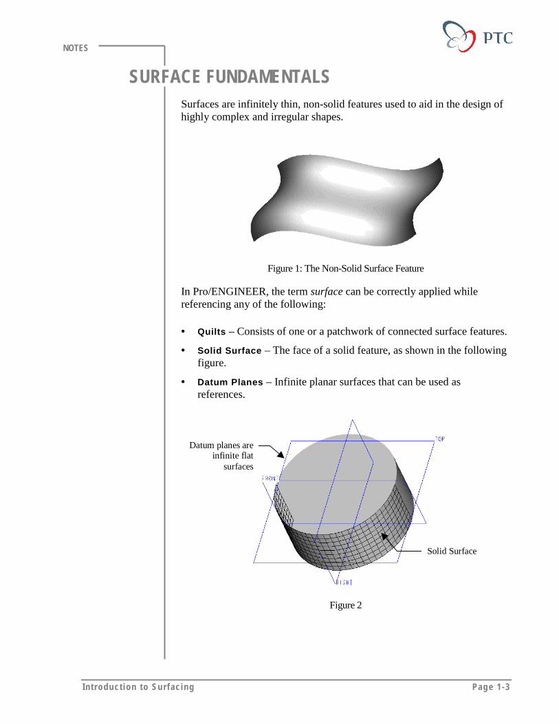
SURFACE FUNDAMENTALSSurfaces are infinitely thin, non-solid features used to aid in the design ofhighly complex and irregular shapes.
Figure 1: The Non-Solid Surface Feature
In Pro/ENGINEER, the term surface can be correctly applied whilereferencing any of the following:
• Quilts – Consists of one or a patchwork of connected surface features.
• Solid Surface – The face of a solid feature, as shown in the followingfigure.
• Datum Planes – Infinite planar surfaces that can be used asreferences.
Solid Surface
Datum planes areinfinite flat
surfaces
Figure 2
Page 1-4 Des igning w i th Surfaces
NOTES
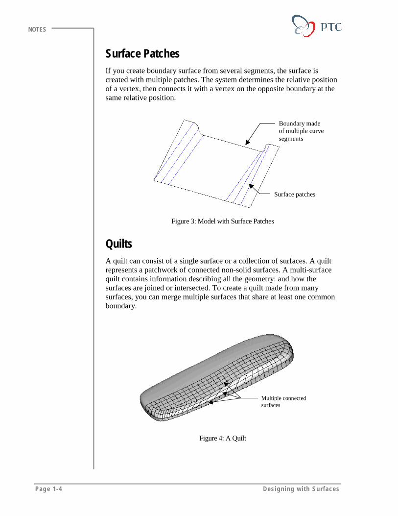
Surface PatchesIf you create boundary surface from several segments, the surface iscreated with multiple patches. The system determines the relative positionof a vertex, then connects it with a vertex on the opposite boundary at thesame relative position.
Boundary madeof multiple curvesegments
Surface patches
Figure 3: Model with Surface Patches
QuiltsA quilt can consist of a single surface or a collection of surfaces. A quiltrepresents a patchwork of connected non-solid surfaces. A multi-surfacequilt contains information describing all the geometry: and how thesurfaces are joined or intersected. To create a quilt made from manysurfaces, you can merge multiple surfaces that share at least one commonboundary.
Multiple connectedsurfaces
Figure 4: A Quilt
In t roduct ion to Surfac ing Page 1-5
NOTES
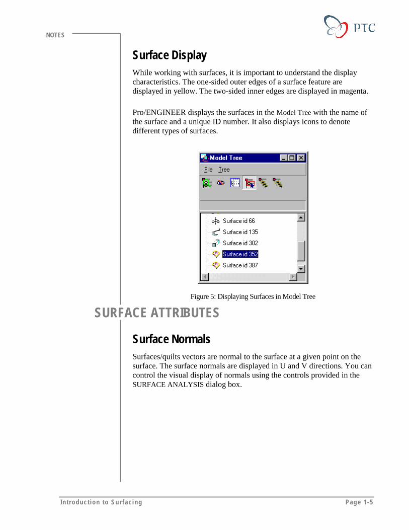
Surface DisplayWhile working with surfaces, it is important to understand the displaycharacteristics. The one-sided outer edges of a surface feature aredisplayed in yellow. The two-sided inner edges are displayed in magenta.
Pro/ENGINEER displays the surfaces in the Model Tree with the name ofthe surface and a unique ID number. It also displays icons to denotedifferent types of surfaces.
Figure 5: Displaying Surfaces in Model Tree
SURFACE ATTRIBUTES
Surface NormalsSurfaces/quilts vectors are normal to the surface at a given point on thesurface. The surface normals are displayed in U and V directions. You cancontrol the visual display of normals using the controls provided in theSURFACE ANALYSIS dialog box.
Page 1-6 Des igning w i th Surfaces
NOTES
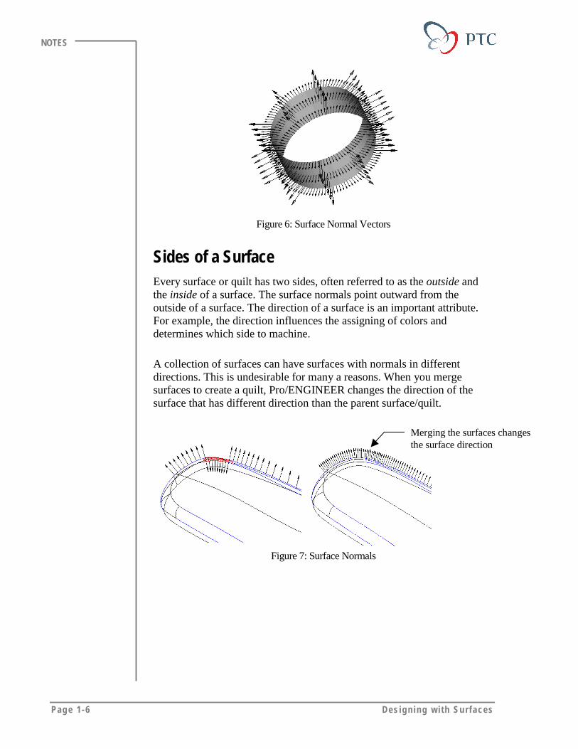
Figure 6: Surface Normal Vectors
Sides of a SurfaceEvery surface or quilt has two sides, often referred to as the outside andthe inside of a surface. The surface normals point outward from theoutside of a surface. The direction of a surface is an important attribute.For example, the direction influences the assigning of colors anddetermines which side to machine.
A collection of surfaces can have surfaces with normals in differentdirections. This is undesirable for many a reasons. When you mergesurfaces to create a quilt, Pro/ENGINEER changes the direction of thesurface that has different direction than the parent surface/quilt.
Merging the surfaces changesthe surface direction
Figure 7: Surface Normals

In t roduct ion to Surfac ing Page 1-7
NOTES
CurvatureCurvature measures the local bending of a surface. Curvature can becalculated as the reciprocal of the radius (1/radius) at any surface point, asshown in the following figure.
In general, it signifies how much a curve or surface bends at a particularlocation on the curve or surface, for example:
• If a circle has constant curvature.
• If a straight line has zero curvature.
Figure 8: The Concept of Curvature
Figure 9: Surface Curvature Displayed in U and V Direction

Page 1-8 Des igning w i th Surfaces
NOTES
Surface ContinuitiesTo join the surfaces smoothly, you need to define the continuity betweenadjacent surfaces. There are two types of continuity that you can define.
• Tangent Continuity – Joins two surfaces that have the same tangentat every point along the boundary.
• Curvature Continuity – Joins two surfaces that have the samecurvature from each surface at each point along the boundary.
Figure 10: Tangent and Curvature Continuous Surfaces
CREATING SURFACESSurface creation in Pro/ENGINNER requires a different approach than thesolids creation. You need to develop reference entities, such as points in acurve, in order to create surfaces. It is recommended that you plan themodel before you start to create the surface models. Your design intentdetermines the tool that you use to create a particular surface. To createsurfaces, you use a number of tools that can be classified in following twocategories:
• Simple or Basic – Surface creation methods that are similar to thesolid creation tools. Some of the basic surface creation tools areExtrusion, Sweep and Blend.
• Advanced – Surfacing tools that allow you to create complex shapesand to control the surface design through complex parameters.
In t roduct ion to Surfac ing Page 1-9
NOTES
Surface Creation TechniquesDatum points and curves are the underlying structures to build thesurfaces. For example, they are required to define boundaries or to definetrajectories.
Pro/ENGINEER provides several methods for creation of models fromsurface.
Curve Network
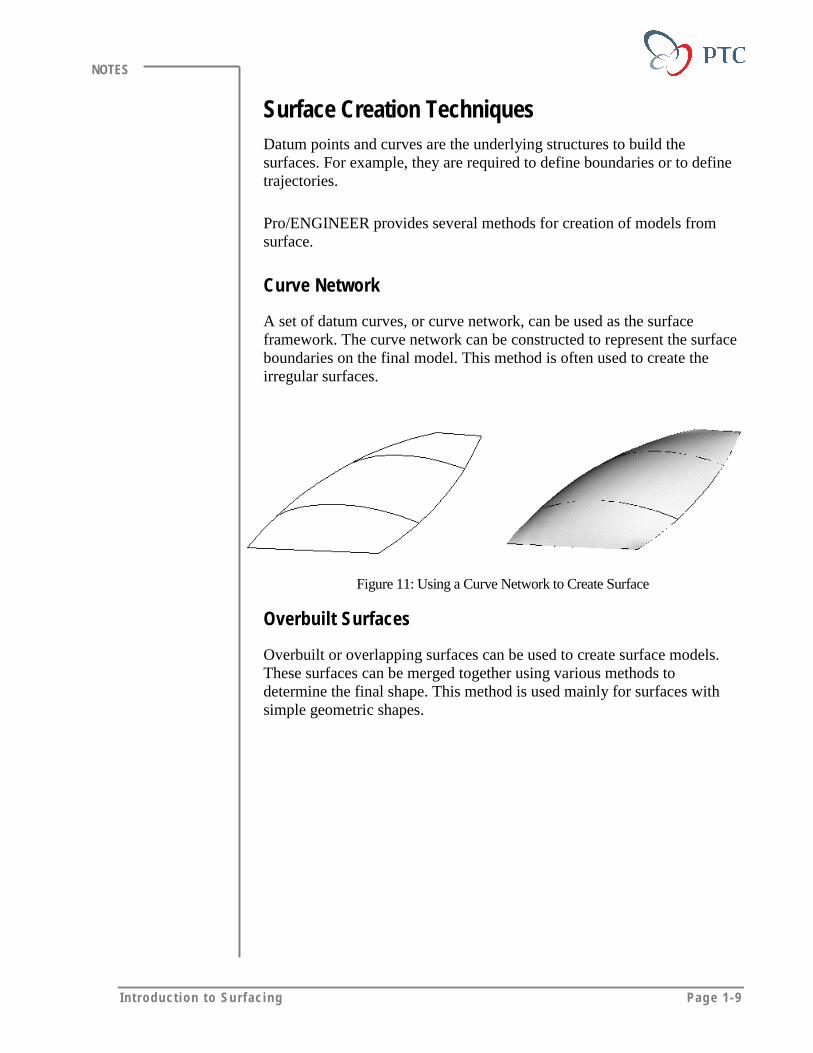
A set of datum curves, or curve network, can be used as the surfaceframework. The curve network can be constructed to represent the surfaceboundaries on the final model. This method is often used to create theirregular surfaces.
Figure 11: Using a Curve Network to Create Surface
Overbuilt Surfaces
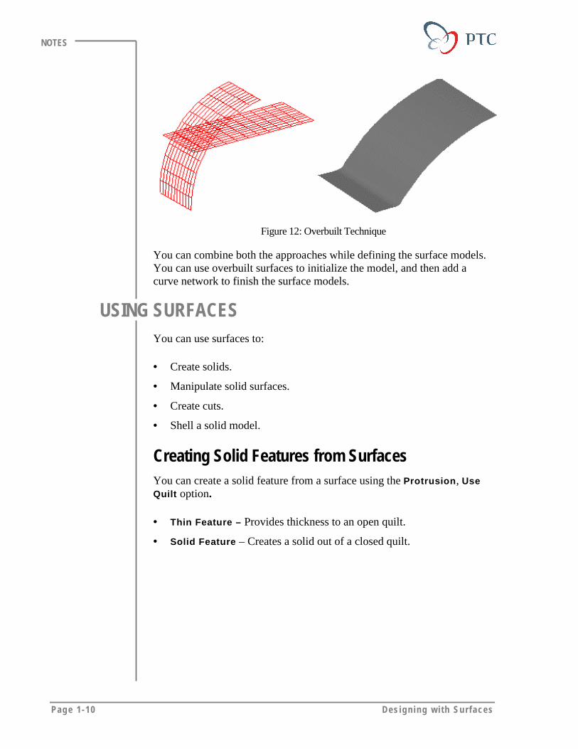
Overbuilt or overlapping surfaces can be used to create surface models.These surfaces can be merged together using various methods todetermine the final shape. This method is used mainly for surfaces withsimple geometric shapes.
Page 1-10 Des igning w i th Surfaces
NOTES
Figure 12: Overbuilt Technique
You can combine both the approaches while defining the surface models.You can use overbuilt surfaces to initialize the model, and then add acurve network to finish the surface models.
USING SURFACESYou can use surfaces to:
• Create solids.
• Manipulate solid surfaces.
• Create cuts.
• Shell a solid model.
Creating Solid Features from SurfacesYou can create a solid feature from a surface using the Protrusion, UseQuilt option.
• Thin Feature – Provides thickness to an open quilt.
• Solid Feature – Creates a solid out of a closed quilt.

In t roduct ion to Surfac ing Page 1-11
NOTES
Figure 13: A Thin Solid Feature
Manipulating Solid SurfacesYou can use quilts to change the shape of a solid surface using thefollowing Tweak options:
• Replace
• Patch
• Free Form
Removing Material from a SolidYou can use quilts to change the shape of solids, for example:
• Cuts – Uses quilts to remove material.
• Shell – Uses quilts to shell a solid model that has complex surfacesand standard shell command is not able to generate the desired results.
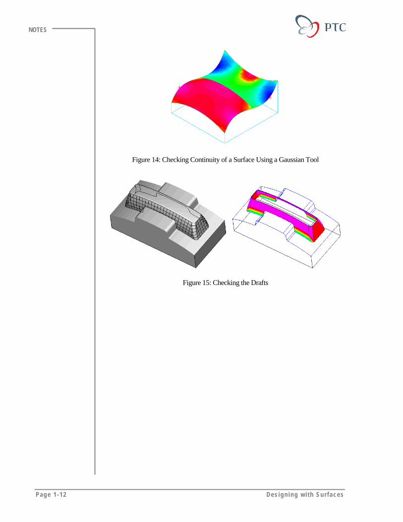
ANALYZING SURFACESPro/ENGINEER offers a number of tools to analyze various aspects ofsurfaces. In order to achieve smooth and complex surfaces, you need toanalyze the surfaces using various tools. You can evaluate surfaces to:
• Find out the continuities (smoothness) of the surfaces.
• Determine the surface quality of imported surfaces.
• Determine the aesthetic attributes of a design.
Page 1-12 Des igning w i th Surfaces
NOTES
Figure 14: Checking Continuity of a Surface Using a Gaussian Tool
Figure 15: Checking the Drafts

In t roduct ion to Surfac ing Page 1-13
NOTES
MODULE SUMMERYIn this module, you have learned that:
• You can use surfaces to define complex shapes.
• In Pro/ENGINEER, the term surface can be referred to a quilt, solidsurface and a datum plane.
• Working with surface modeling requires a different approach thansolids modeling.
• In order to achieve smooth and quality surfaces, you need to analyzethe surfaces.


Page 2-1
Module
Initial SurfacesIn this module you learn to create basic surface features.
Objectives
After completing this module, you will be able to:
• Define and create initial surfaces.
• Define the attributes that are unique to the surfaces.
Page 2-2 Des igning w i th Surfaces
NOTES
CREATING SURFACESSurface features extend the functionality of Pro/ENGINEER. Thoughmost of the initial surfaces are created using the tools that are similar tosolid protrusions, there are subtle differences, such as specifying tangentboundary conditions.
You can use following surfacing methods to create simple surfacefeatures:
• Extrude
• Revolve
• Sweep
• Blend
• Flat
• Offset
• Copy
• Fillet
You can create complex surfaces using following advance surfacingmethods:
• Variable Section Sweep
• Swept Blend
• Helical Sweeps
• Boundaries
• Section To Surfaces
• Surfaces to Surfaces
• From File
• Tangent To Surfaces
• Free Form
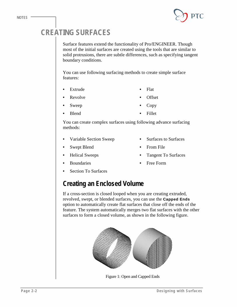
Creating an Enclosed VolumeIf a cross-section is closed looped when you are creating extruded,revolved, swept, or blended surfaces, you can use the Capped Endsoption to automatically create flat surfaces that close off the ends of thefeature. The system automatically merges two flat surfaces with the othersurfaces to form a closed volume, as shown in the following figure.
Figure 1: Open and Capped Ends

In i t i a l Surfaces Page 2-3
NOTES
EXTRUDED SURFACESYou can create a surface by extruding a sketched section to a specifieddepth in the direction normal to the sketching plane.
Figure 2: Extruded surface with an Open Section
Extruding a surface is similar to extruding a solid thin feature using theSolid, Protrusion, Thin command. You can sketch an open or closedsection to extrude.
Defining Depth
You can define the depth of an extruded surface using the followingoptions:
• Blind
• Up to Point or Vertex
• Up to Curve
• Up to Surface
Page 2-4 Des igning w i th Surfaces
NOTES
REVOLVED SURFACESYou can create a surface feature by rotating a sketched section around thefirst sketched centerline.
Defining Angle of Rotation
You can specify the angle of rotation using the following options:
• Variable
• Standard Angles
• Up to Point or Vertex
• Up to Plane
BLENDED SURFACESYou can create a blended surface feature by connecting a series ofsketched sections. You need at least two sections to create a blendedsurface. Also, you need to specify the distance between the sections.
AttributesWhile creating a blended surface you can define the transition between thesections using following options:
• Smooth – Creates a smooth blend by connecting vertices of differentsections with smooth curves. Edges of the sections are connected withspline surfaces.
• Straight – Creates a straight blend by connecting vertices of thedifferent sections with straight lines. Edges of the sections areconnected with ruled surfaces.
Orienting the SectionsYou can choose one of the following options to orient the sections.
• Parallel
• Rotational
• General

In i t i a l Surfaces Page 2-5
NOTES
Parallel Blends
You create a parallel blend by sketching sections that remain parallel tothe sketching plane. You can define the distance between the planes.
Figure 3: Straight & Smooth Blend
Rotational Blends
Sections can be rotated about the Y-axis of a sketcher coordinate systemup to a maximum of 120 degrees. You need to define a coordinate systemin order to specify the rotation.
Figure 4: Rotational Blend
General Blends
Sections can be rotated about and translated along the X, Y, and Z-axes.You need to specify a coordinate system in order to align the sections.This enables parametric control of a twisted blend.
Page 2-6 Des igning w i th Surfaces
NOTES
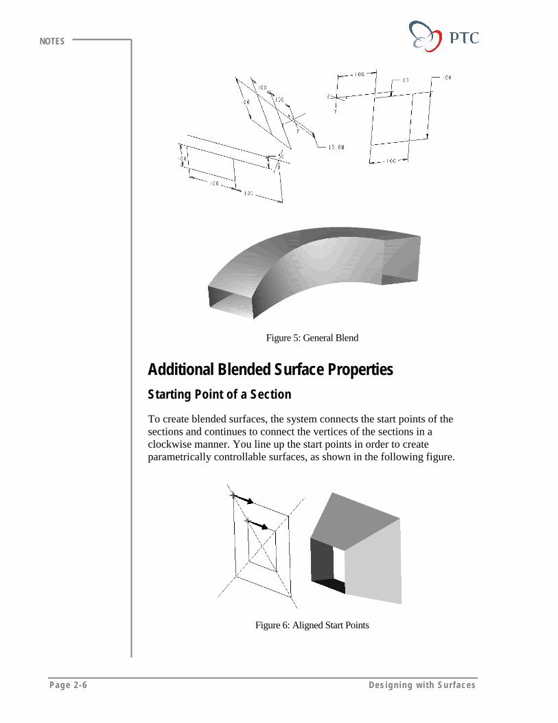
Figure 5: General Blend
Additional Blended Surface PropertiesStarting Point of a Section
To create blended surfaces, the system connects the start points of thesections and continues to connect the vertices of the sections in aclockwise manner. You line up the start points in order to createparametrically controllable surfaces, as shown in the following figure.
Figure 6: Aligned Start Points

In i t i a l Surfaces Page 2-7
NOTES
If the start points do not line up, the surface twists, as shown in thefollowing figure.
Figure 7: Unaligned Start Points Produce a Twisted Surface
Specifying Tangent Surfaces
You can make a blended surface tangential to the adjacent surfaces asshown in the following figure.
Blended surfacetangent to the
meshed surface
Figure 8
Blend Vertex
The each section of a blend must always contain the same number ofentities. If the sections do not have enough entities, you can add blendvertices. Each blend vertex adds one entity to the section. The followingfigure shows the smooth blending between two squares and a triangle.
Page 2-8 Des igning w i th Surfaces
NOTES
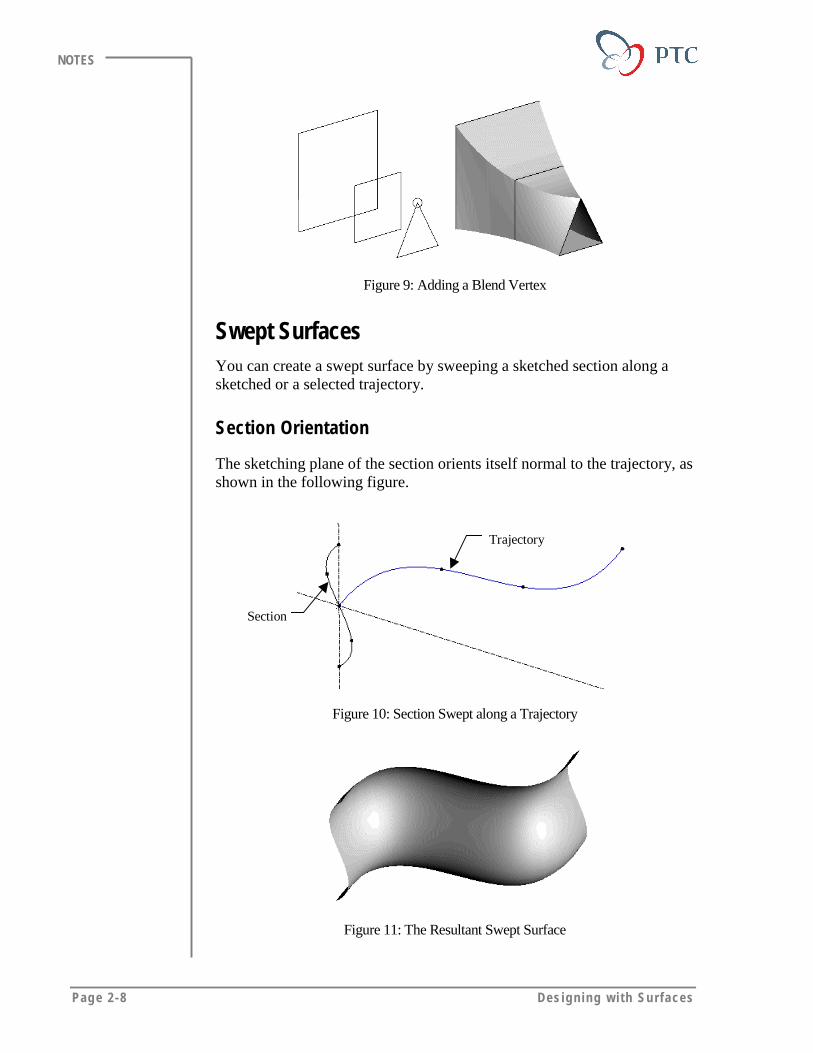
Figure 9: Adding a Blend Vertex
Swept SurfacesYou can create a swept surface by sweeping a sketched section along asketched or a selected trajectory.
Section Orientation
The sketching plane of the section orients itself normal to the trajectory, asshown in the following figure.
Section
Trajectory
Figure 10: Section Swept along a Trajectory
Figure 11: The Resultant Swept Surface

In i t i a l Surfaces Page 2-9
NOTES
Defining a Trajectory
You can define a trajectory by sketching it or by selecting datum curves orthe edges. As a general rule, the trajectory must have adjacent referencesurfaces or be planar. You can sketch or select a trajectory that has:
• Open curves or edges.
• Closed curves or edges.
• Non-tangent segments.
Figure 12: A Swept Surface with Non-Tangent Trajectory
Attributes of Swept SurfacesAdding Inner Faces
You can add inner faces while sweeping an open section along a closedtrajectory.
Figure 13: Sweeping an Open Section along a Closed Trajectory
Figure 14: Resultant Swept Feature without Inner Faces
Page 2-10 Des igning w i th Surfaces
NOTES
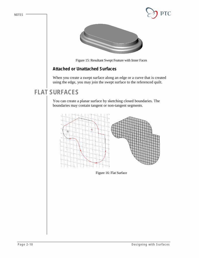
Figure 15: Resultant Swept Feature with Inner Faces
Attached or Unattached Surfaces
When you create a swept surface along an edge or a curve that is createdusing the edge, you may join the swept surface to the referenced quilt.
FLAT SURFACESYou can create a planar surface by sketching closed boundaries. Theboundaries may contain tangent or non-tangent segments.
Figure 16: Flat Surface
In i t i a l Surfaces Page 2-11
NOTES
USING SURFACES TO CREATE ADDITIONALSURFACES
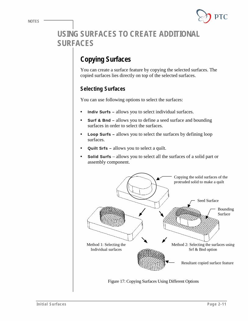
Copying SurfacesYou can create a surface feature by copying the selected surfaces. Thecopied surfaces lies directly on top of the selected surfaces.
Selecting Surfaces
You can use following options to select the surfaces:
• Indiv Surfs – allows you to select individual surfaces.
• Surf & Bnd – allows you to define a seed surface and boundingsurfaces in order to select the surfaces.
• Loop Surfs – allows you to select the surfaces by defining loopsurfaces.
• Quilt Srfs – allows you to select a quilt.
• Solid Surfs – allows you to select all the surfaces of a solid part orassembly component.
Copying the solid surfaces of theprotruded solid to make a quilt
Resultant copied surface feature
Method 1: Selecting theIndividual surfaces
Seed Surface
BoundingSurface
Method 2: Selecting the surfaces usingSrf & Bnd option
Figure 17: Copying Surfaces Using Different Options

Page 2-12 Des igning w i th Surfaces
NOTES
Selection Options
• Excluding the Loops – you can exclude loops from the surfaces thatyou are copying using the Excld Loops option.
Excluding the leftsurface using ExcldLoops option
Cut feature
Figure 18: Copying Surfaces Using Excld Loops Option
• Filling the Loops – you can include the filled contours of the loopsfrom the surfaces that you are copying using the Fill Loops option.
Selecting a loopin order to selectthe entire surface
A solid surfaceselected bydefault
Figure 19: Copying Surfaces Using Fill Loops Option
Offset SurfacesYou can create an offset surface of a solid surface or a quilt usingfollowing options.
• Normal to Surface
• Auto Fit
• Controlled Fit
Offset features are discussed in detail in another module.
In i t i a l Surfaces Page 2-13
NOTES
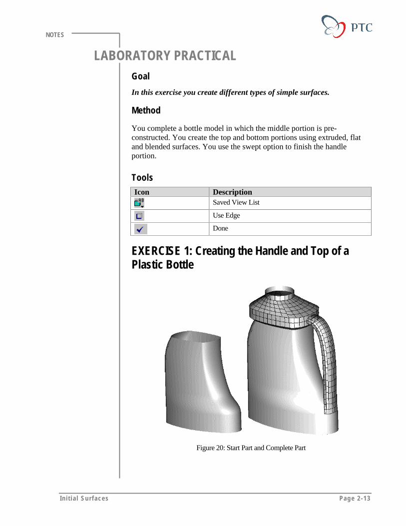
LABORATORY PRACTICALGoal
In this exercise you create different types of simple surfaces.
Method
You complete a bottle model in which the middle portion is pre-constructed. You create the top and bottom portions using extruded, flatand blended surfaces. You use the swept option to finish the handleportion.
ToolsIcon Description
Saved View List
Use Edge
Done
EXERCISE 1: Creating the Handle and Top of aPlastic Bottle
Figure 20: Start Part and Complete Part
Page 2-14 Des igning w i th Surfaces
NOTES
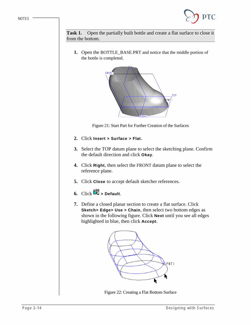
Task 1. Open the partially built bottle and create a flat surface to close itfrom the bottom.
1. Open the BOTTLE_BASE.PRT and notice that the middle portion ofthe bottle is completed.
Figure 21: Start Part for Further Creation of the Surfaces
2. Click Insert > Surface > Flat.
3. Select the TOP datum plane to select the sketching plane. Confirmthe default direction and click Okay.
4. Click Right, then select the FRONT datum plane to select thereference plane.
5. Click Close to accept default sketcher references.
6. Click > Default.
7. Define a closed planar section to create a flat surface. ClickSketch> Edge> Use > Chain, then select two bottom edges asshown in the following figure. Click Next until you see all edgeshighlighted in blue, then click Accept.
Figure 22: Creating a Flat Bottom Surface
In i t i a l Surfaces Page 2-15
NOTES
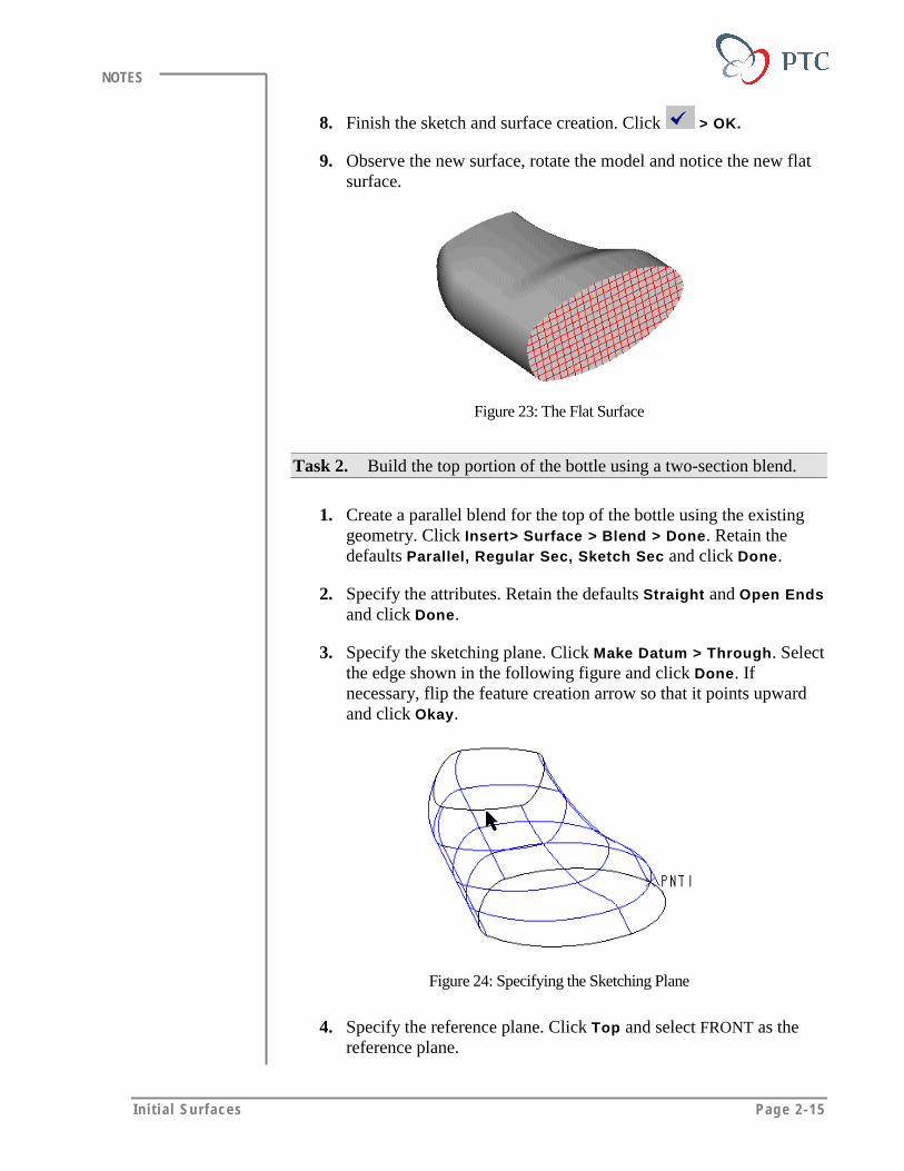
8. Finish the sketch and surface creation. Click > OK.
9. Observe the new surface, rotate the model and notice the new flatsurface.
Figure 23: The Flat Surface
Task 2. Build the top portion of the bottle using a two-section blend.
1. Create a parallel blend for the top of the bottle using the existinggeometry. Click Insert> Surface > Blend > Done. Retain thedefaults Parallel, Regular Sec, Sketch Sec and click Done.
2. Specify the attributes. Retain the defaults Straight and Open Endsand click Done.
3. Specify the sketching plane. Click Make Datum > Through. Selectthe edge shown in the following figure and click Done. Ifnecessary, flip the feature creation arrow so that it points upwardand click Okay.
Figure 24: Specifying the Sketching Plane
4. Specify the reference plane. Click Top and select FRONT as thereference plane.

Page 2-16 Des igning w i th Surfaces
NOTES
5. Close the REFERENCES dialog box and click Yes to continuesketching.
6. Click View > Default Orientation.
7. Sketch the first section. Click Sketch > Edge > Use > Chain.Select the two edges as shown in the following figure.
Figure 25
8. Specify the chain of edges. Click Next until all edges arehighlighted in blue. Click Accept to select all edges.
Figure 26: Specifying the Chain of Edges
Tips & Techniques:
To use the Chain option, you must select two edgessimultaneously (edge of surface versus a datum curve).
9. Note the start point and toggle to the next section. Click Sketch >Feature Tools > Toggle Section. Note and confirm that the cyansection is now gray.
In i t i a l Surfaces Page 2-17
NOTES
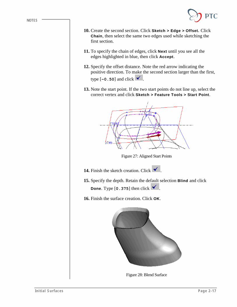
10. Create the second section. Click Sketch > Edge > Offset. ClickChain, then select the same two edges used while sketching thefirst section.
11. To specify the chain of edges, click Next until you see all theedges highlighted in blue, then click Accept.
12. Specify the offset distance. Note the red arrow indicating thepositive direction. To make the second section larger than the first,
type [-0.50] and click .
13. Note the start point. If the two start points do not line up, select thecorrect vertex and click Sketch > Feature Tools > Start Point.
Figure 27: Aligned Start Points
14. Finish the sketch creation. Click .
15. Specify the depth. Retain the default selection Blind and click
Done. Type [0.375] then click .
16. Finish the surface creation. Click OK.
Figure 28: Blend Surface
Page 2-18 Des igning w i th Surfaces
NOTES
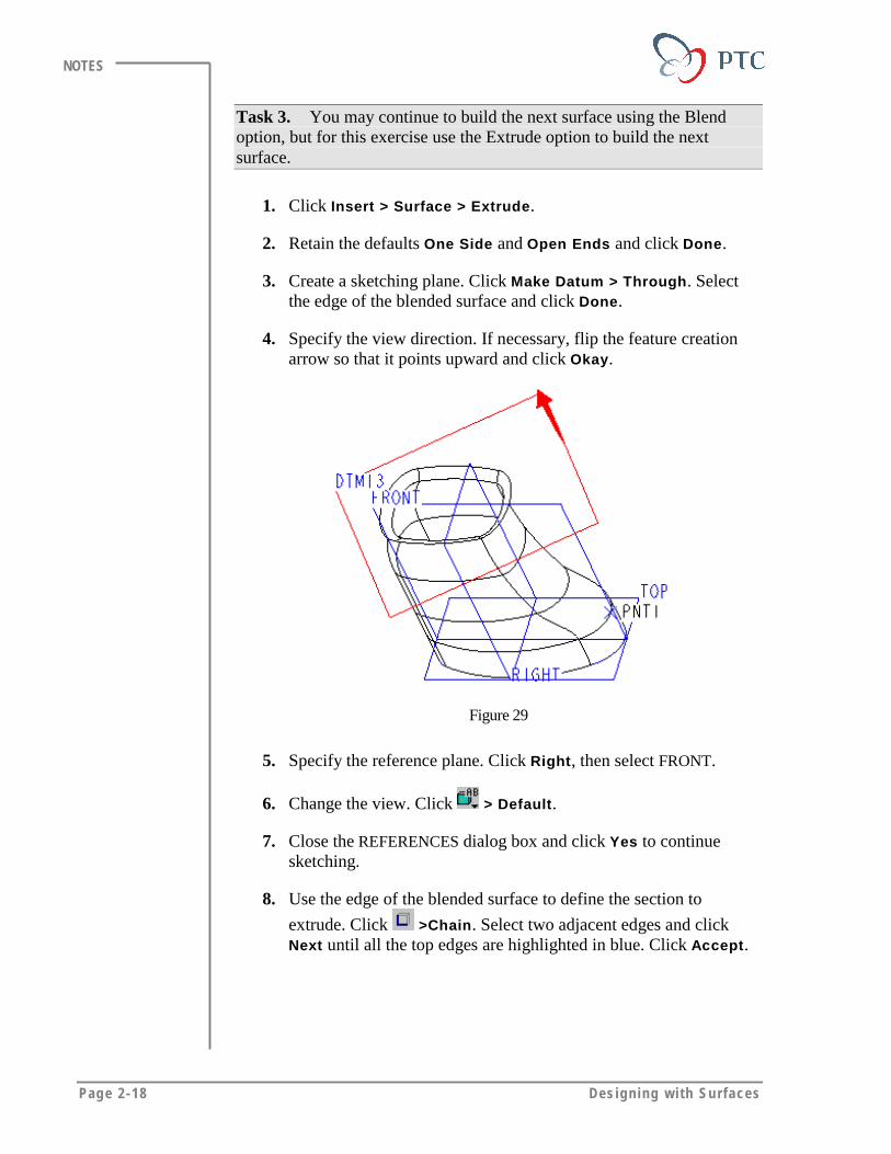
Task 3. You may continue to build the next surface using the Blendoption, but for this exercise use the Extrude option to build the nextsurface.
1. Click Insert > Surface > Extrude.
2. Retain the defaults One Side and Open Ends and click Done.
3. Create a sketching plane. Click Make Datum > Through. Selectthe edge of the blended surface and click Done.
4. Specify the view direction. If necessary, flip the feature creationarrow so that it points upward and click Okay.
Figure 29
5. Specify the reference plane. Click Right, then select FRONT.
6. Change the view. Click > Default.
7. Close the REFERENCES dialog box and click Yes to continuesketching.
8. Use the edge of the blended surface to define the section to
extrude. Click >Chain. Select two adjacent edges and clickNext until all the top edges are highlighted in blue. Click Accept.

In i t i a l Surfaces Page 2-19
NOTES
Figure 30
9. Finish the sketch. Click .
10. Specify the feature depth. Retain the default Blind and click Done.
11. Define the height of the extruded surface. Type [1], then click .
12. Finish the surface creation. Click OK.
Figure 31: Bottle after Adding Surface Extrude Feature
Task 4. Create the next surface using parallel blend. For the firstsection, use the same edge that you used to create the surface extendfeature. Make the second section circular.
1. Create a parallel blend. Click Insert > Surface > Blend.
Page 2-20 Des igning w i th Surfaces
NOTES
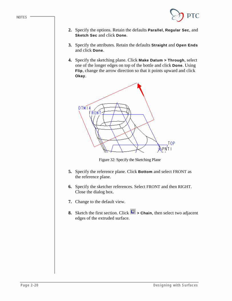
2. Specify the options. Retain the defaults Parallel, Regular Sec, andSketch Sec and click Done.
3. Specify the attributes. Retain the defaults Straight and Open Endsand click Done.
4. Specify the sketching plane. Click Make Datum > Through, selectone of the longer edges on top of the bottle and click Done. UsingFlip, change the arrow direction so that it points upward and clickOkay.
Figure 32: Specify the Sketching Plane
5. Specify the reference plane. Click Bottom and select FRONT asthe reference plane.
6. Specify the sketcher references. Select FRONT and then RIGHT.Close the dialog box.
7. Change to the default view.
8. Sketch the first section. Click > Chain, then select two adjacentedges of the extruded surface.
In i t i a l Surfaces Page 2-21
NOTES
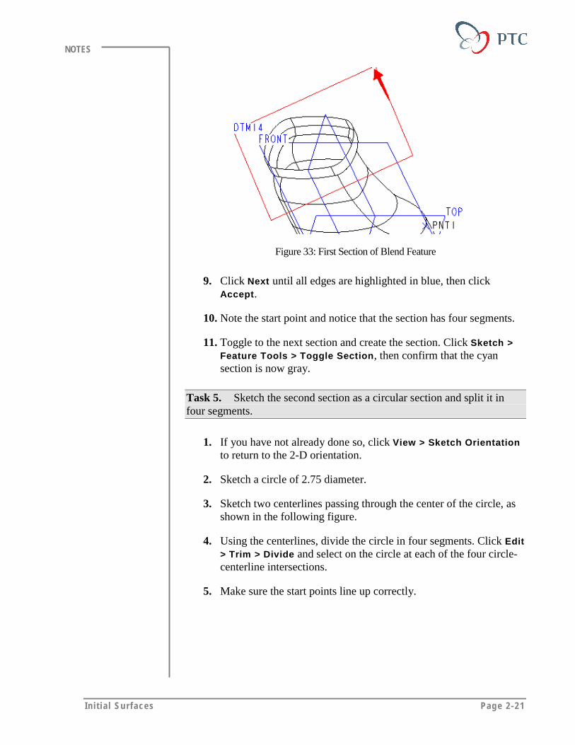
Figure 33: First Section of Blend Feature
9. Click Next until all edges are highlighted in blue, then clickAccept.
10. Note the start point and notice that the section has four segments.
11. Toggle to the next section and create the section. Click Sketch >Feature Tools > Toggle Section, then confirm that the cyansection is now gray.
Task 5. Sketch the second section as a circular section and split it infour segments.
1. If you have not already done so, click View > Sketch Orientationto return to the 2-D orientation.
2. Sketch a circle of 2.75 diameter.
3. Sketch two centerlines passing through the center of the circle, asshown in the following figure.
4. Using the centerlines, divide the circle in four segments. Click Edit> Trim > Divide and select on the circle at each of the four circle-centerline intersections.
5. Make sure the start points line up correctly.
Page 2-22 Des igning w i th Surfaces
NOTES
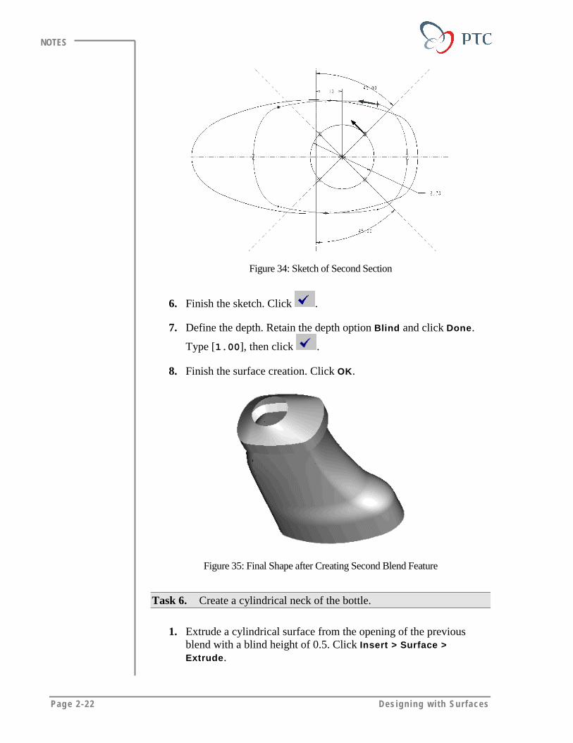
Figure 34: Sketch of Second Section
6. Finish the sketch. Click .
7. Define the depth. Retain the depth option Blind and click Done.
Type [1.00], then click .
8. Finish the surface creation. Click OK.
Figure 35: Final Shape after Creating Second Blend Feature
Task 6. Create a cylindrical neck of the bottle.
1. Extrude a cylindrical surface from the opening of the previousblend with a blind height of 0.5. Click Insert > Surface >Extrude.

In i t i a l Surfaces Page 2-23
NOTES
2. Retain the default attributes One Side and Open Ends, then clickDone.
3. Specify the sketching plane. Click Make Datum > Through, selectthe top circle of the bottle, and click Done.
4. Specify the upward viewing direction and click Okay.
5. To specify the reference plane, click Bottom and select FRONT.
6. To specify the sketcher references, select RIGHT and FRONT.
7. Close the dialog box.
8. Change to the default view.
9. Sketch the section. Click . Copy the existing edges of the circle.
10. Finish the sketch and specify the blind depth. Type [0.5] and click
. The finished surface should look similar to the one shown inthe following figure.
Figure 36: Finished Top Portion of the Bottle
Task 7. Build the handle of the bottle, using Sweep. Before creating thesweep, create datum points to define the trajectory.
1. Create a datum point on the surface. Click Insert > Datum > Point> On Surface.
Page 2-24 Des igning w i th Surfaces
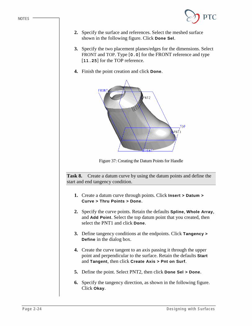
NOTES
2. Specify the surface and references. Select the meshed surfaceshown in the following figure. Click Done Sel.
3. Specify the two placement planes/edges for the dimensions. SelectFRONT and TOP. Type [0.0] for the FRONT reference and type[11.25] for the TOP reference.
4. Finish the point creation and click Done.
Figure 37: Creating the Datum Points for Handle
Task 8. Create a datum curve by using the datum points and define thestart and end tangency condition.
1. Create a datum curve through points. Click Insert > Datum >Curve > Thru Points > Done.
2. Specify the curve points. Retain the defaults Spline, Whole Array,and Add Point. Select the top datum point that you created, thenselect the PNT1 and click Done.
3. Define tangency conditions at the endpoints. Click Tangency >Define in the dialog box.
4. Create the curve tangent to an axis passing it through the upperpoint and perpendicular to the surface. Retain the defaults Startand Tangent, then click Create Axis > Pnt on Surf.
5. Define the point. Select PNT2, then click Done Sel > Done.
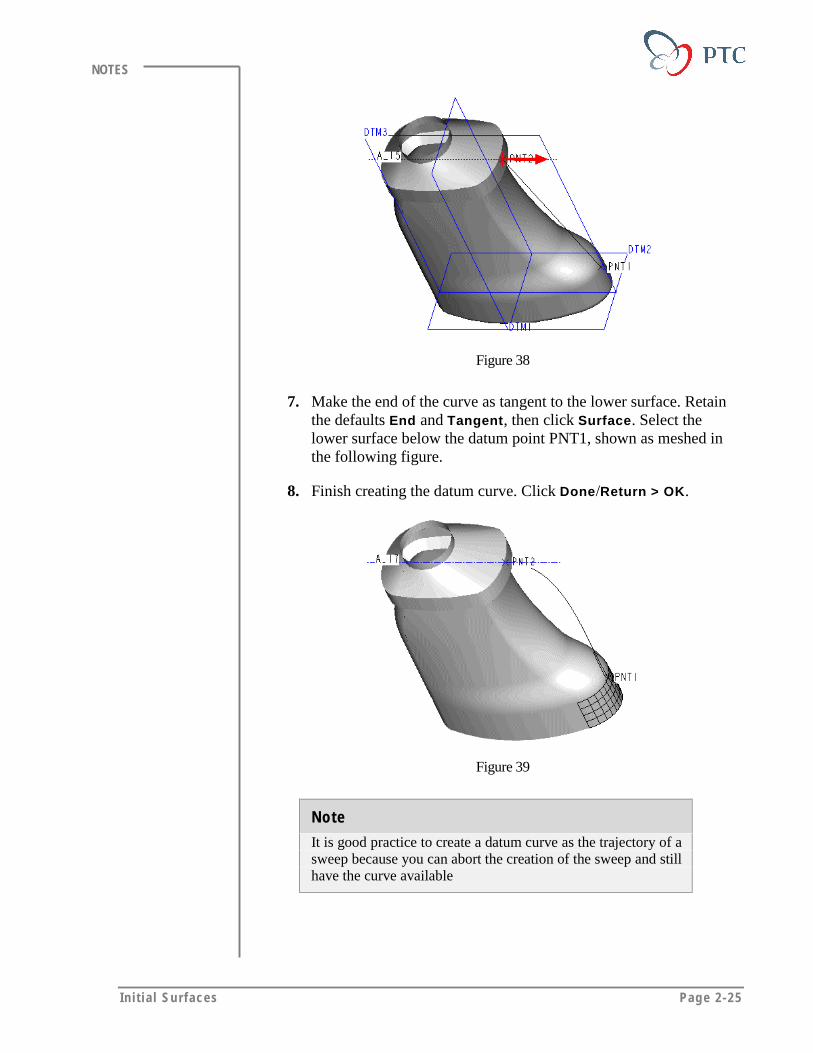
6. Specify the tangency direction, as shown in the following figure.Click Okay.
In i t i a l Surfaces Page 2-25
NOTES
Figure 38
7. Make the end of the curve as tangent to the lower surface. Retainthe defaults End and Tangent, then click Surface. Select thelower surface below the datum point PNT1, shown as meshed inthe following figure.
8. Finish creating the datum curve. Click Done/Return > OK.
Figure 39
Note
It is good practice to create a datum curve as the trajectory of asweep because you can abort the creation of the sweep and stillhave the curve available
Page 2-26 Des igning w i th Surfaces
NOTES
Task 9. Build the bottle handle using the Sweep option. Use the curvethat you created as the trajectory.
1. Create a swept surface. Click Insert > Surface > Sweep > SelectTraj.
2. To specify the trajectory, retain the defaults One By One andSelect. Select the datum curve that you created previously, thenclick Done Sel and Done.
3. Accept the default direction and click Okay.
4. To specify the attributes, retain Open Ends and click Done.
5. Accept the default sketcher references and close the dialog box.
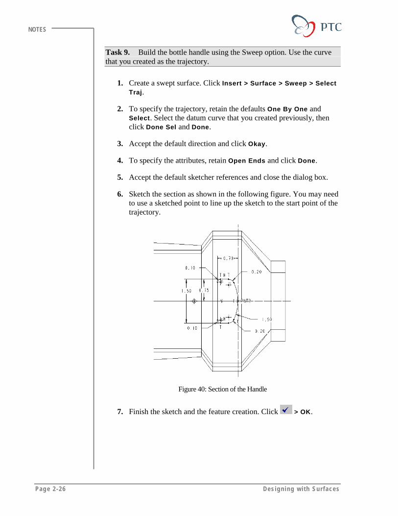
6. Sketch the section as shown in the following figure. You may needto use a sketched point to line up the sketch to the start point of thetrajectory.
Figure 40: Section of the Handle
7. Finish the sketch and the feature creation. Click > OK.
In i t i a l Surfaces Page 2-27
NOTES
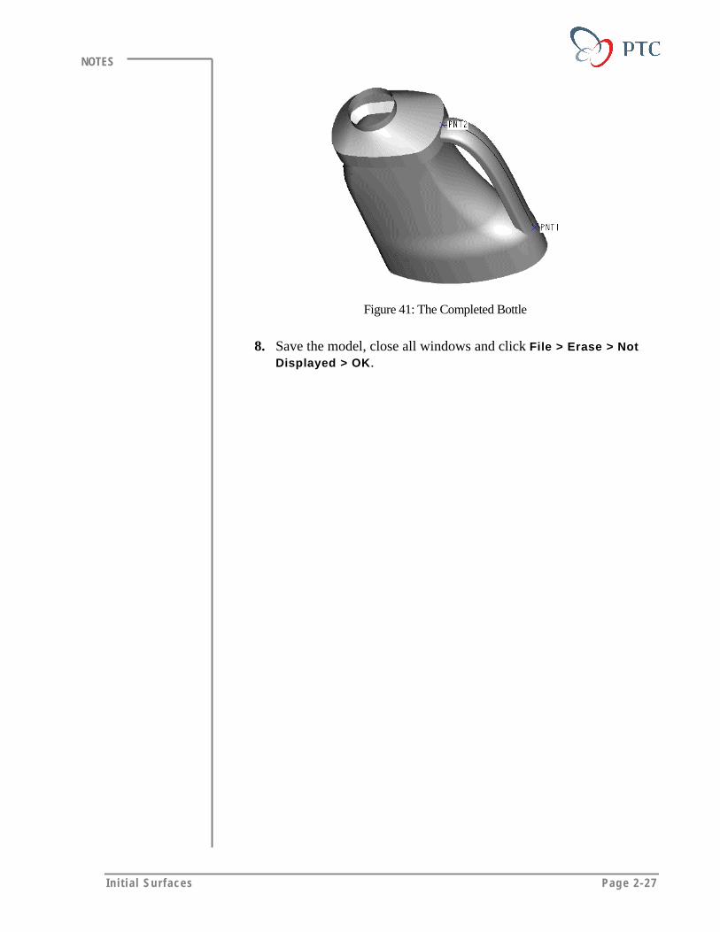
Figure 41: The Completed Bottle
8. Save the model, close all windows and click File > Erase > NotDisplayed > OK.
Page 2-28 Des igning w i th Surfaces
NOTES
MODULE SUMMARYIn this module, you have learned that:
• Pro/ENGINEER creates simple surfaces similar to the way solids arecreated.
• Unlike solid features, surface features allow the user to add tangencyand curvature constraints.
• Multiple surfaces can be joined to create larger complete surfaces.
• You can copy solid surfaces to create a surface feature.
Page 3-1
Module
Geometry for Surfaces: Points & CurvesDatum points and datum curves are the building blocks of surface
features. In this module you learn to create points and datum curves.
Objectives
After completing this module, you will be able to:
• Define and create datum points using various options.
• Define and create datum curves using various options.
• Define and create sketched splines and conics.
Page 3-2 Des igning w i th Surfaces
NOTES
DATUM POINTSDatum points are used to specify loads for mesh generation, attach datumtargets and notes, create coordinate systems and pipe trajectories. Whilecreating surfaces, you use datum points to:
• Create datum curves.
• Locate coordinate systems, datum planes, and datum axes.
• Define variable radius rounds.
• Specify the position of a sweep cross-section along a trajectory.
Creating Datum PointsTo create datum points, you can use all of following options:
• On Surface
• Offset Surf
• Curve X Srf
• On Vertex
• Offset Sys
• Three Srf
• At Center
• On Curve
• Crv X Crv
• Offset point
• Field Point
• Sketch
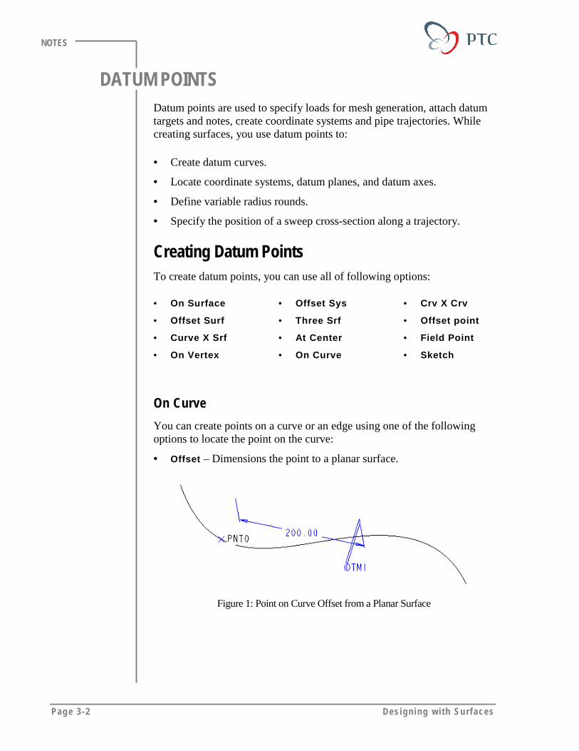
On Curve
You can create points on a curve or an edge using one of the followingoptions to locate the point on the curve:
• Offset – Dimensions the point to a planar surface.
Figure 1: Point on Curve Offset from a Planar Surface

Geom et ry for Surfaces: Points and Curves Page 3-3
NOTES
• Length Ratio – Expresses the distance from the point to the curvevertex as a ratio of the total length of the curve, shown in the followingfigure as a fraction in decimal form.
Figure 2: Point on Curve as Length Ratio
• Actual Length – Dimensions the point by measuring a specificdistance from the vertex of the curve.
On Surface
You can create points on a surface by dimensioning it with respect to twodatum planes or edges.
Figure 3: Points on Surface Dimensioned to Two Datum Planes
On Vertex
You can create points on the vertex of a part edge, surface feature edge,and ends of a datum curve.
Figure 4: Points on Vertex

Page 3-4 Des igning w i th Surfaces
NOTES
Note
When creating surfaces from points and curves, you shouldalways consider the level of complexity. If you create a surfacefrom curves through points, those original points subsequentlycontrol and dimension the surface, which could make itdifficult to change later.
DATUM CURVESDatum curves play an important role while creating surfaces. You can usethem to define:
• Trajectories for sweeps or blends
• Boundaries of blended surfaces
Creating Datum CurvesTo create datum curves, you can use the following options:
• Sketch
• Intr. Surfs
• Thru Points
• From File
• Composite
• UseXsec
• Projected
• Formed
• Split
• OffsetFromSrf
• From Curve
• FromBoundary
• Offset Curve
• 2 Projections
• From Equation
Sketched Datum Curves
You can create planar curves using the sketcher. Sketched curves canconsist of one or more sketched segments and of one or more open orclosed loops. As you sketch the datum curves, Pro/ENGINEER creates asingle composite datum curve on top of discrete sketched datum curvesegments.

Geom et ry for Surfaces: Points and Curves Page 3-5
NOTES
Sketching Splines and ConicsWhile creating free form or style surfaces, you are often required to sketchsplines and conic curves.
Sketched Splines
A spline consists of a series of points through which a smooth curvepasses.
Figure 5: Spline through a Series of Points
Defining Tangency
A spline can be sketched free form or its endpoints can be defined tangentto existing geometry. You can apply tangency constraint or provide aspecific angle to define end point tangency, as shown in the followingfigure.
Figure 6: End-Point Tangency

Page 3-6 Des igning w i th Surfaces
NOTES
Dimensioning Splines
• You can use tangent vector angles to dimension a spline. You candefine the vector angles for the end points and the intermediate points.
Figure 7
• You can define the linear dimensions to locate the endpoints or anyintermediate points, as shown in the following figure.
Figure 8
• To define the tangency at the endpoints, you can specify the radius oftangency. To control the curvature of a tangent, you can change theradius of curvature, as shown in the following figure.
Figure 9
Geom et ry for Surfaces: Points and Curves Page 3-7
NOTES
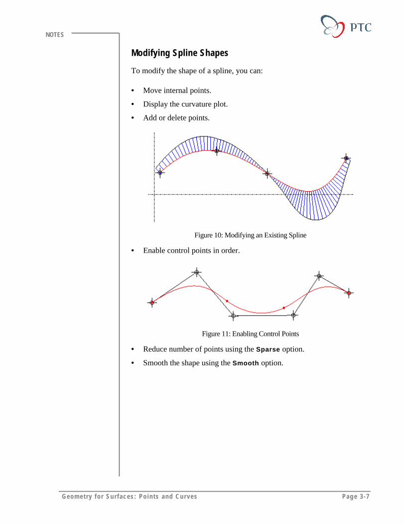
Modifying Spline Shapes
To modify the shape of a spline, you can:
• Move internal points.
• Display the curvature plot.
• Add or delete points.
Figure 10: Modifying an Existing Spline
• Enable control points in order.
Figure 11: Enabling Control Points
• Reduce number of points using the Sparse option.
• Smooth the shape using the Smooth option.

Page 3-8 Des igning w i th Surfaces
NOTES
Sketched Conics
You can sketch a conic entity with three points, two endpoints and anintermediate point. The shape of a conic is controlled by the shape factorrho, as shown in the following figures. If you increase the value of rho,the peak of a conic becomes sharper.
The values of rho are:
Ellipse 0.05 < rho < 0.5
Parabola rho = 0.5
Hyperbola 0.5 < rho < 0.95
Figure 12: Rho Value Defines a Conic
Figure 13: Sharper Peak with Higher Value of rho
Geom et ry for Surfaces: Points and Curves Page 3-9
NOTES
Defining Curves through the PointsYou can create a curve through a series of datum points. You can also useedge vertices and the end of the curves as the through points.
The system offers three choices to create a curve through the selectedpoints:
• Spline – Creates a 3D spline passing through the points.
• Single Radius – Creates a curve using the same radius through all thebends.
• Multiple Radius – Creates a curve by specifying a radius for eachbend.
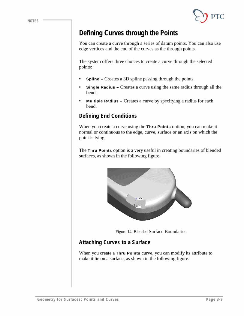
Defining End Conditions
When you create a curve using the Thru Points option, you can make itnormal or continuous to the edge, curve, surface or an axis on which thepoint is lying.
The Thru Points option is a very useful in creating boundaries of blendedsurfaces, as shown in the following figure.
Figure 14: Blended Surface Boundaries
Attaching Curves to a Surface
When you create a Thru Points curve, you can modify its attribute tomake it lie on a surface, as shown in the following figure.

Page 3-10 Des igning w i th Surfaces
NOTES
Figure 15: A Thru Points Curve attached to a Surface
Modifying the Shape of the Curve
You can modify the shape of the curve by manipulating it in a 3D space oron a specific surface. While modifying the curve a number of curveanalysis tools are also available to you. If you tweak a curve, the systemmaintains the tangency conditions that you assigned at the ends of thecurve, as shown in the following figure.
Figure 16: Tangency Conditions
Geom et ry for Surfaces: Points and Curves Page 3-11
NOTES
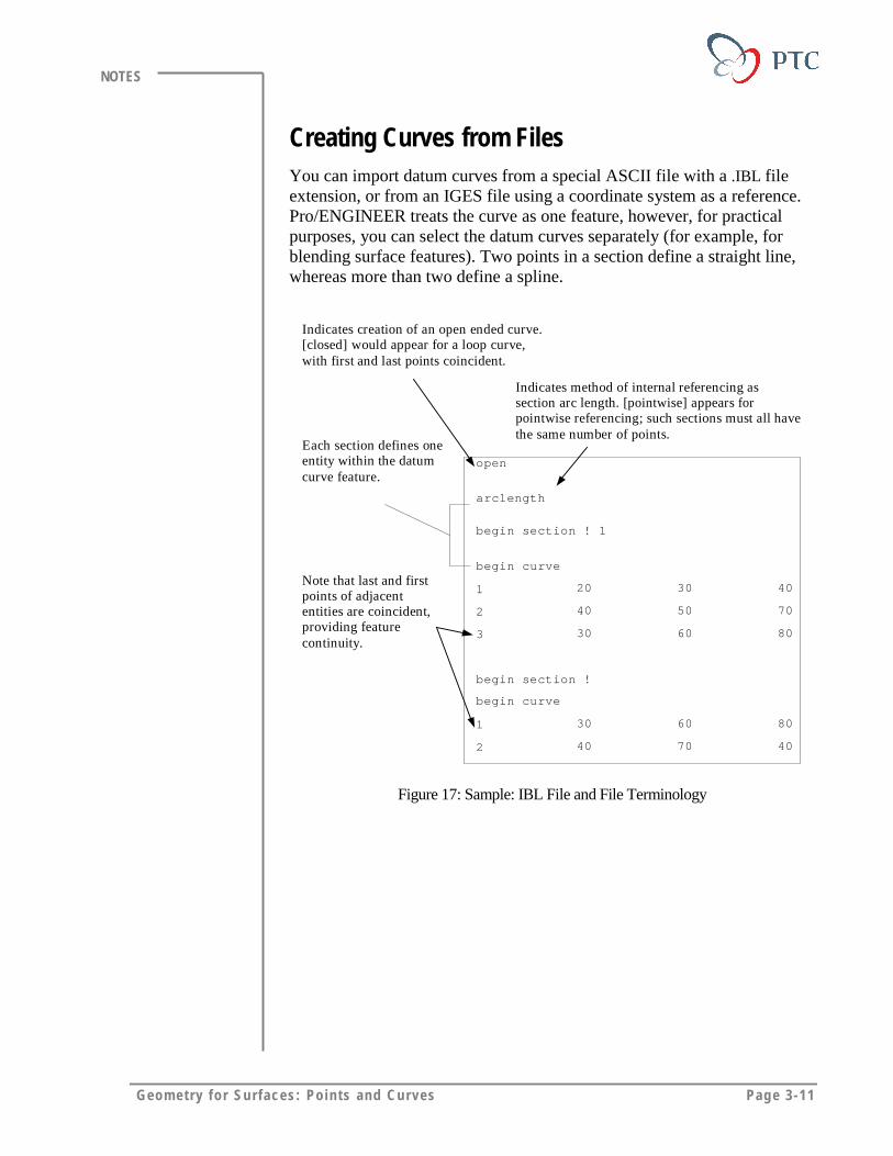
Creating Curves from FilesYou can import datum curves from a special ASCII file with a .IBL fileextension, or from an IGES file using a coordinate system as a reference.Pro/ENGINEER treats the curve as one feature, however, for practicalpurposes, you can select the datum curves separately (for example, forblending surface features). Two points in a section define a straight line,whereas more than two define a spline.
open
arclength
begin section ! 1
begin curve
1 20 30 40
2 40 50 70
3 30 60 80
begin section !
begin curve
1 30 60 80
2 40 70 40
Indicates creation of an open ended curve.[closed] would appear for a loop curve,with first and last points coincident.
Indicates method of internal referencing assection arc length. [pointwise] appears forpointwise referencing; such sections must all havethe same number of points.
Each section defines oneentity within the datumcurve feature.
Note that last and firstpoints of adjacententities are coincident,providing featurecontinuity.
Figure 17: Sample: IBL File and File Terminology

Page 3-12 Des igning w i th Surfaces
NOTES
Redefining the From File Curves
Pro/ENGINEER allows you to redefine the curves that are read from afile. You can use following options to redefine them:
• Edit file – Allows you to manually edit the points.
• Create – Adds additional curves.
• Spline Pnts – As an alternative to manually changing the curves withthe Edit File option, assists the adjustment process.
� Sparse – Reduces the number of points.
� Smooth – Makes the spline smoother.
� Add – Adds points to increase the control.
� Remove – Allows you to remove points individually.
� Move – Allows you to move spline points.
� Show – Displays the points along a spline.
� Blank – Turns off the display of points along a spline.
• Adjust – Adjusts two curves so that they intersect.
• Trim/Extend – Trims or extends a curve up to a surface.
• Split – Splits one curve into two curves.
• Merge – Merges two curves into one.
• Delete – Deletes curves from the feature.
• Measure – Accesses the INFO CURVE menu for calculations.
Composite Datum CurvesYou can combine datum curves using part edges and surface feature edgesto create a composite curve.
Use composite curves to:
• Remove small surfaces from the design
• Create a single surface with continuous curvature
• Attain better surface aesthetics.
Geom et ry for Surfaces: Points and Curves Page 3-13
NOTES
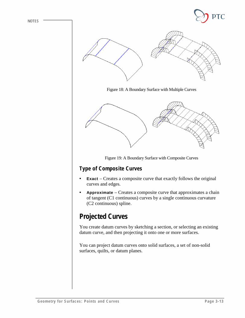
Figure 18: A Boundary Surface with Multiple Curves
Figure 19: A Boundary Surface with Composite Curves
Type of Composite Curves
• Exact – Creates a composite curve that exactly follows the originalcurves and edges.
• Approximate – Creates a composite curve that approximates a chainof tangent (C1 continuous) curves by a single continuous curvature(C2 continuous) spline.
Projected CurvesYou create datum curves by sketching a section, or selecting an existingdatum curve, and then projecting it onto one or more surfaces.
You can project datum curves onto solid surfaces, a set of non-solidsurfaces, quilts, or datum planes.
Page 3-14 Des igning w i th Surfaces
NOTES
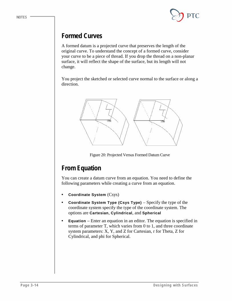
Formed CurvesA formed datum is a projected curve that preserves the length of theoriginal curve. To understand the concept of a formed curve, consideryour curve to be a piece of thread. If you drop the thread on a non-planarsurface, it will reflect the shape of the surface, but its length will notchange.
You project the sketched or selected curve normal to the surface or along adirection.
Figure 20: Projected Versus Formed Datum Curve
From EquationYou can create a datum curve from an equation. You need to define thefollowing parameters while creating a curve from an equation.
• Coordinate System (Csys)
• Coordinate System Type (Csys Type) – Specify the type of thecoordinate system specify the type of the coordinate system. Theoptions are Cartesian, Cylindrical, and Spherical
• Equation – Enter an equation in an editor. The equation is specified interms of parameter T, which varies from 0 to 1, and three coordinatesystem parameters: X, Y, and Z for Cartesian, r for Theta, Z forCylindrical, and phi for Spherical.

Geom et ry for Surfaces: Points and Curves Page 3-15
NOTES
From BoundaryYou can create a datum curve that is offset from a surface boundary. Youcan select an edge and define the offset distance from the end points of theedge. You can specify the offset distance either normal to the boundary oralong the edge.
Figure 21: Datum Curve Offset from Boundary
Offset from SurfaceYou can create an offset curve from a curve that is lying on a surface. Theshape and the distance of the offset curve are controlled by a graph.
Figure 22: Curve Offset from Surface
Page 3-16 Des igning w i th Surfaces
NOTES
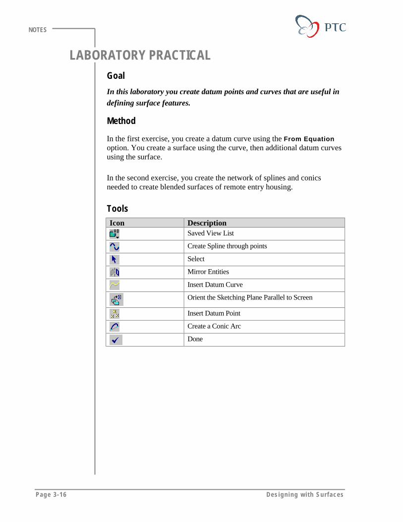
LABORATORY PRACTICALGoal
In this laboratory you create datum points and curves that are useful in
defining surface features.
Method
In the first exercise, you create a datum curve using the From Equationoption. You create a surface using the curve, then additional datum curvesusing the surface.
In the second exercise, you create the network of splines and conicsneeded to create blended surfaces of remote entry housing.
ToolsIcon Description
Saved View List
Create Spline through points
Select
Mirror Entities
Insert Datum Curve
Orient the Sketching Plane Parallel to Screen
Insert Datum Point
Create a Conic Arc
Done
Geom et ry for Surfaces: Points and Curves Page 3-17
NOTES
EXERCISE 1: Creating Datum Curves
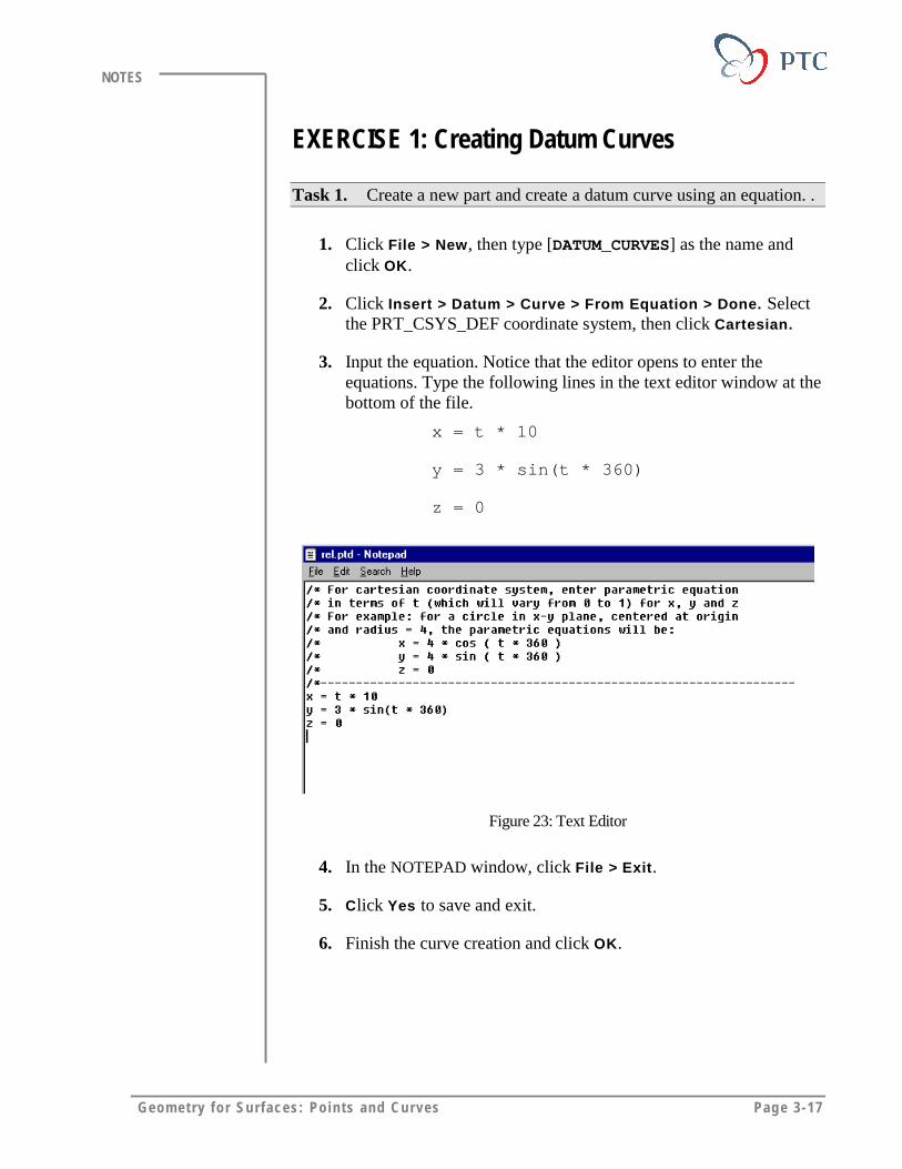
Task 1. Create a new part and create a datum curve using an equation. .
1. Click File > New, then type [DATUM_CURVES] as the name andclick OK.
2. Click Insert > Datum > Curve > From Equation > Done. Selectthe PRT_CSYS_DEF coordinate system, then click Cartesian.
3. Input the equation. Notice that the editor opens to enter theequations. Type the following lines in the text editor window at thebottom of the file.
x = t * 10
y = 3 * sin(t * 360)
z = 0
Figure 23: Text Editor
4. In the NOTEPAD window, click File > Exit.
5. Click Yes to save and exit.
6. Finish the curve creation and click OK.
Page 3-18 Des igning w i th Surfaces
NOTES
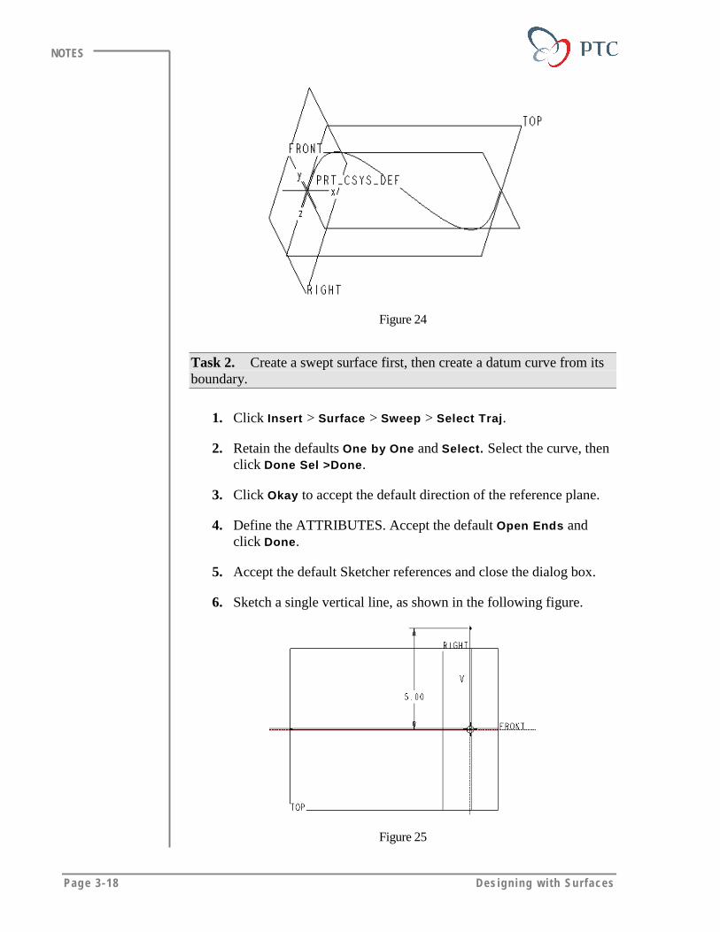
Figure 24
Task 2. Create a swept surface first, then create a datum curve from itsboundary.
1. Click Insert > Surface > Sweep > Select Traj.
2. Retain the defaults One by One and Select. Select the curve, thenclick Done Sel >Done.
3. Click Okay to accept the default direction of the reference plane.
4. Define the ATTRIBUTES. Accept the default Open Ends andclick Done.
5. Accept the default Sketcher references and close the dialog box.
6. Sketch a single vertical line, as shown in the following figure.
Figure 25

Geom et ry for Surfaces: Points and Curves Page 3-19
NOTES
7. Click > OK to finish the sketch and surface creation.
8. Change to the default view.
Figure 26: The Swept Surface
9. To create a boundary datum curve, click > From Bndry >Done.
10. Select the boundary. Retain the defaults One By One and Select.Select the front sine wave-shaped edge of the swept surface, thenclick Done Sel > Done.
Tips & Techniques:
If you select the wrong edge, you can use Unselect.
11. Specify the left vertex offset:
� Retain the default Sel Pnt/Vert and select the left vertex tospecify its offset.
� Retain the options Specify Dist and Norm to Bnd. ClickAccept.
� Type [2.0], then click .
12. Specify the right vertex offset.
� Retain the default Sel Pnt/Vert and select the right vertex.
� Retain the options Specify Dist and Norm to Bnd. ClickAccept.
� Type [0.5], then click .

Page 3-20 Des igning w i th Surfaces
NOTES
13. Complete the feature. Click Done/Return>Done Extend.
Figure 27
Task 3. Create a datum curve that is offset from the surface. Also, createa graph to control the offset distance.
1. Click Insert > Datum > Graph. Type [OFFSET] and click .
2. Sketch the section, as shown in the following figure. Remember toadd the Sketcher coordinate system.
Center lines
Sketched coordinate system Single Line section
Figure 28
3. Finish the graph creation. Click .

Geom et ry for Surfaces: Points and Curves Page 3-21
NOTES
4. Click > OffsetFromSrf > Done.
5. Select the curve from which to offset. Select the boundary datumcurve that you just created in the previous task.
6. Specify the start point at the left side of the curve, and then clickOkay.
7. Select the swept surface to specify the surface from which tooffset.
8. Define the direction, as shown in the following figure, then clickOkay.
Figure 29
9. Specify a datum graph for the offset value. Click Sel By Menu. Inthe SELECTION TOOLS dialog box, select OFFSET. Click Select.
10. Specify the scale. Type [1.0], then click .
11. Observe the Offset curve in the FRONT view. Click > FRONT.
Figure 30: Offset from Surface Datum Curve
Page 3-22 Des igning w i th Surfaces
NOTES
12. Change to the default view.
Task 4. Create a datum curve by projecting it onto the surface that youcreated earlier. Also, form a datum curve onto the surface and compare theresults.
1. Click > Projected > Done > Sketch > Done.
2. Set up a sketching plane. Click Make Datum > Offset. SelectTOP.
3. Define the offset value. Click Enter Value. Type [5], then click
> Done.
4. Click Okay to accept the default viewing direction.
5. Make sure that the arrow, showing direction for projecting thesketch, points towards the surface, and then click Okay.
6. Click RIGHT and select RIGHT as the reference plane.
7. Accept the default sketch references and close the REFERENCESdialog box.
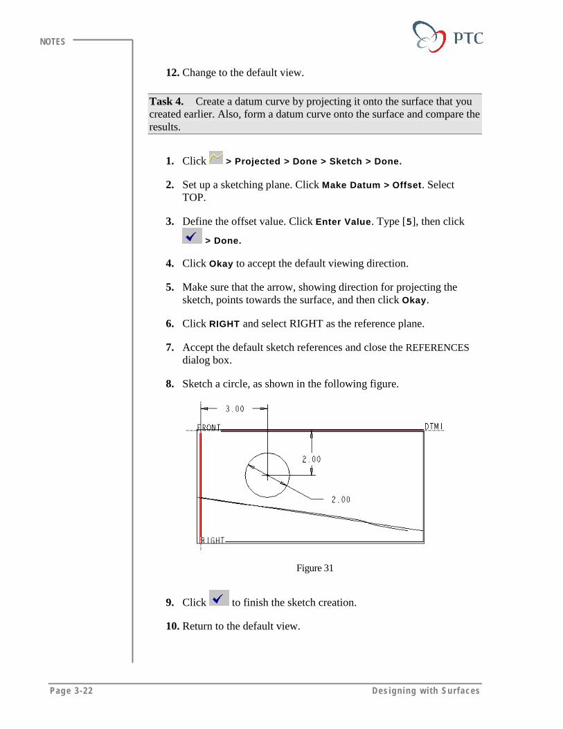
8. Sketch a circle, as shown in the following figure.
Figure 31
9. Click to finish the sketch creation.
10. Return to the default view.

Geom et ry for Surfaces: Points and Curves Page 3-23
NOTES
11. Specify the projection surface. Retain the defaults Surfaces >Include > Indiv Surfs. Select the surface, then click Done Sel>Done.
12. Specify the projection type. Click Norm to Sket > Done.
Note:
The second option, Norm to Surf, projects the sketch normalto the selected surface.
13. Click OK from the dialog box to finish the curve creation.
Figure 32: Projected Curve
Task 5. Create a datum curve by forming it onto the surface that youcreated earlier.
1. Click Insert > Datum > Curve > Formed > Done. Click QuiltSurfs to form the sketch on a surface feature.
2. Specify the sketching and reference plane. Click Use Prev so thatthe system uses the previously selected sketching references.
3. Click Okay to accept the default viewing direction.
4. Confirm that the arrow showing direction of feature creation pointstowards the surface, and then click Okay.
5. Accept the default sketcher references and close the dialog box.
Page 3-24 Des igning w i th Surfaces
NOTES
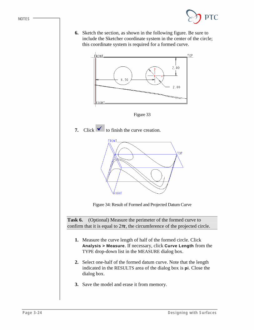
6. Sketch the section, as shown in the following figure. Be sure toinclude the Sketcher coordinate system in the center of the circle;this coordinate system is required for a formed curve.
Figure 33
7. Click to finish the curve creation.
Figure 34: Result of Formed and Projected Datum Curve
Task 6. (Optional) Measure the perimeter of the formed curve toconfirm that it is equal to 2πr, the circumference of the projected circle.
1. Measure the curve length of half of the formed circle. ClickAnalysis > Measure. If necessary, click Curve Length from theTYPE drop-down list in the MEASURE dialog box.
2. Select one-half of the formed datum curve. Note that the lengthindicated in the RESULTS area of the dialog box is pi. Close thedialog box.
3. Save the model and erase it from memory.

Geom et ry for Surfaces: Points and Curves Page 3-25
NOTES
EXERCISE 2: Creating Curves to Build Surfaces
Figure 35: Completed Model Based On Curves
Task 1. Create a new part and begin curve creation.
1. Click File > New, then type [remote_entry] as the name and
click .
2. Click > Sketch > Done.
3. Select TOP as the sketching plane. Click Okay to accept thedefault direction.
4. Click Bottom, then select the FRONT datum plane.
5. Click Close to accept the default sketcher references.
6. Sketch a vertical centerline through the RIGHT datum plane, andzoom in to approximately four grid squares
7. Click to sketch spline. Select the first point on the centerline.Select the second point so that the curve is approximatelyperpendicular to the centerline. Continue to select the points.Create a shape, as shown in the following figure. Middle-click tofinish the spline.
Page 3-26 Des igning w i th Surfaces
NOTES
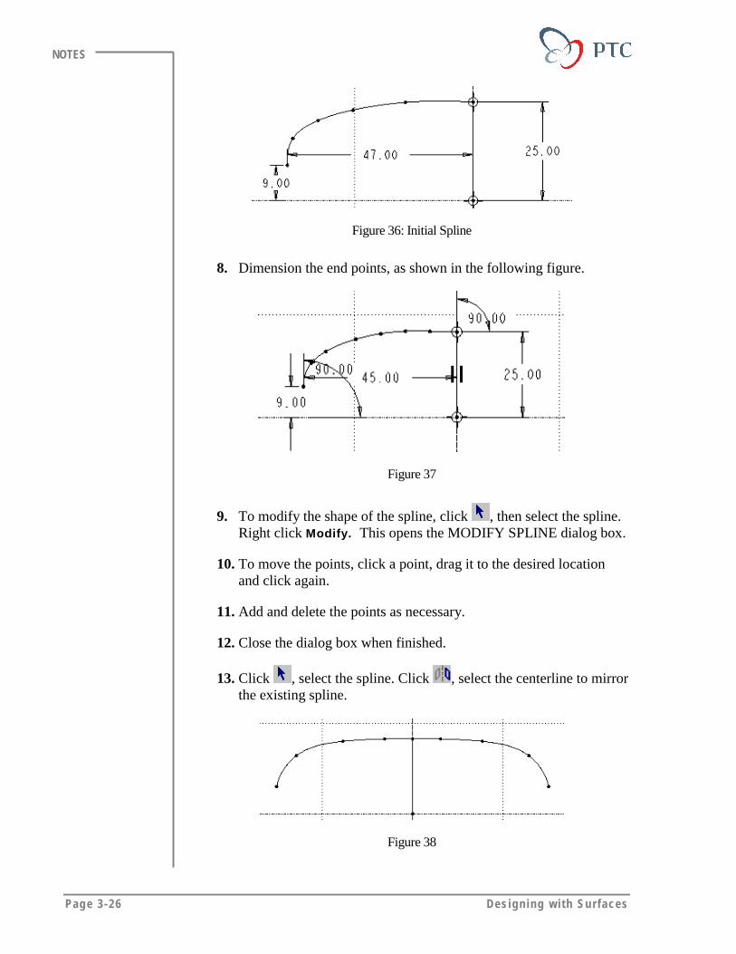
Figure 36: Initial Spline
8. Dimension the end points, as shown in the following figure.
Figure 37
9. To modify the shape of the spline, click , then select the spline.Right click Modify. This opens the MODIFY SPLINE dialog box.
10. To move the points, click a point, drag it to the desired locationand click again.
11. Add and delete the points as necessary.
12. Close the dialog box when finished.
13. Click , select the spline. Click , select the centerline to mirrorthe existing spline.
Figure 38

Geom et ry for Surfaces: Points and Curves Page 3-27
NOTES
Tips & Techniques
While working with spline create as few points as possible todefine the desired shape.
Task 2. Create another spline.
1. Click . Start a new spline at left endpoint of the existing spline.
Figure 39
2. Constrain it as tangent to the first spline.
3. Click , and double-click the spline. Move the points to refinethe shape.
4. Click . Start a new spline at the endpoint of the previous spline.Select the second point so that it is tangent to the previous spline.
5. Dimension the end point so that it is normal to the centerline, asshown in the following figure.
Page 3-28 Des igning w i th Surfaces
NOTES
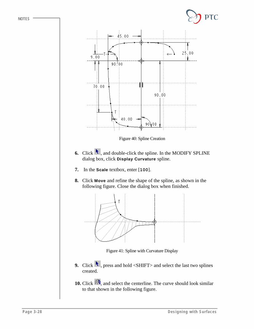
Figure 40: Spline Creation
6. Click , and double-click the spline. In the MODIFY SPLINEdialog box, click Display Curvature spline.
7. In the Scale textbox, enter [100].
8. Click Move and refine the shape of the spline, as shown in thefollowing figure. Close the dialog box when finished.
Figure 41: Spline with Curvature Display
9. Click , press and hold <SHIFT> and select the last two splinescreated.
10. Click , and select the centerline. The curve should look similarto that shown in the following figure.
Geom et ry for Surfaces: Points and Curves Page 3-29
NOTES
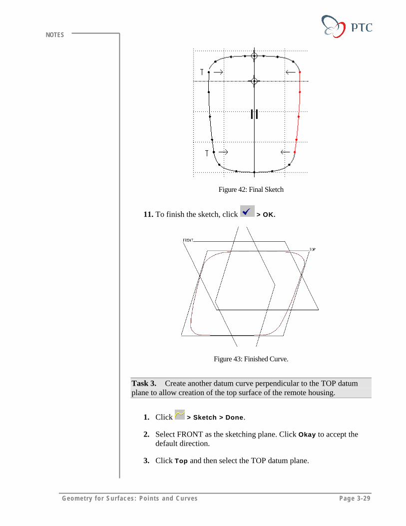
Figure 42: Final Sketch
11. To finish the sketch, click > OK.
Figure 43: Finished Curve.
Task 3. Create another datum curve perpendicular to the TOP datumplane to allow creation of the top surface of the remote housing.
1. Click > Sketch > Done.
2. Select FRONT as the sketching plane. Click Okay to accept thedefault direction.
3. Click Top and then select the TOP datum plane.

Page 3-30 Des igning w i th Surfaces
NOTES
4. In the REFERENCES dialog box, select F2 (TOP) and clickDelete.
5. Rotate the model to the default orientation, and select the portionsof the existing curve that intersects FRONT, as shown in thefollowing figure. Close the REFERENCES dialog box whenfinished.
Figure 44: Selecting References
6. Click to return to the sketch view.
7. Create a centerline through RIGHT.
8. Sketch a horizontal line offset from the curve, and symmetricabout the centerline.
Figure 45: Horizontal Symmetric Line

Geom et ry for Surfaces: Points and Curves Page 3-31
NOTES
9. From the ARC fly-out icons, click . Create two conics startingon the datum curve and tangent to the end points of the horizontalline, as shown in the following figure.
Figure 46: Creating Conics Tangent to Line
10. Finish the sketch by clicking > OK.
Task 4. The second datum curves will be created perpendicular to theTOP datum using datum points.
4. Click > On Vertex > Query Sel. Select at the approximateintersection of the uppermost splines, as shown in the followingfigure. When highlighted, click Accept > Done Sel.
Figure 47: Modifying Spline Shape
5. Click On Vertex > Query Sel. Select the opposite vertex of thesplines. When highlighted, click Accept > Done Sel > Done>Done. You should see two points, as shown in the followingfigure.
Figure 48: Point Creation

Page 3-32 Des igning w i th Surfaces
NOTES
6. Click > Thru Points > Done.
7. Select the two points. Click Done.
8. Click Tangency > Define > Surface > Normal. Select the TOPdatum plane and click Okay.
9. Click Surface > Normal. Select the TOP datum plane.
10. Click Flip > Okay > Done/Return> OK.
Figure 49: Second Curve
Task 5. Build the final curve by creating a datum that passes through thevertices of the splines.
1. Click > Sketch > Done >Make Datum > Through. Click allthe options except Point/Vertex so that they are not highlighted.
2. Click Query Sel. Select the vertex of the lower spines. ClickAccept.
3. Click Through, then click all the options except Point/Vertex sothat they are not highlighted. Click Query Sel, select the oppositespline vertex, and click Accept.
4. Click Parallel, select the FRONT datum plane and click Done.Accept the default viewing direction, click Okay.

Geom et ry for Surfaces: Points and Curves Page 3-33
NOTES
Figure 50
5. Click Top, then select the TOP datum plane.
6. Reorient the model to the default orientation, and select the datumcurve endpoints as additional references. Close the REFERENCESdialog box.
7. Click to return to the sketch view.
8. Click . Start a new spline starting and ending on the verticesselected as references. Sketch the spline slightly smaller than theprevious curves, as shown in the following figure.
Figure 51: Third Spline
9. Click , and double-click the spline. In the MODIFY SPLINEdialog box, click Control Points. Drag the white control points todefine a shape similar to that shown in the following figure. Closethe MODIFY SPLINE dialog box.
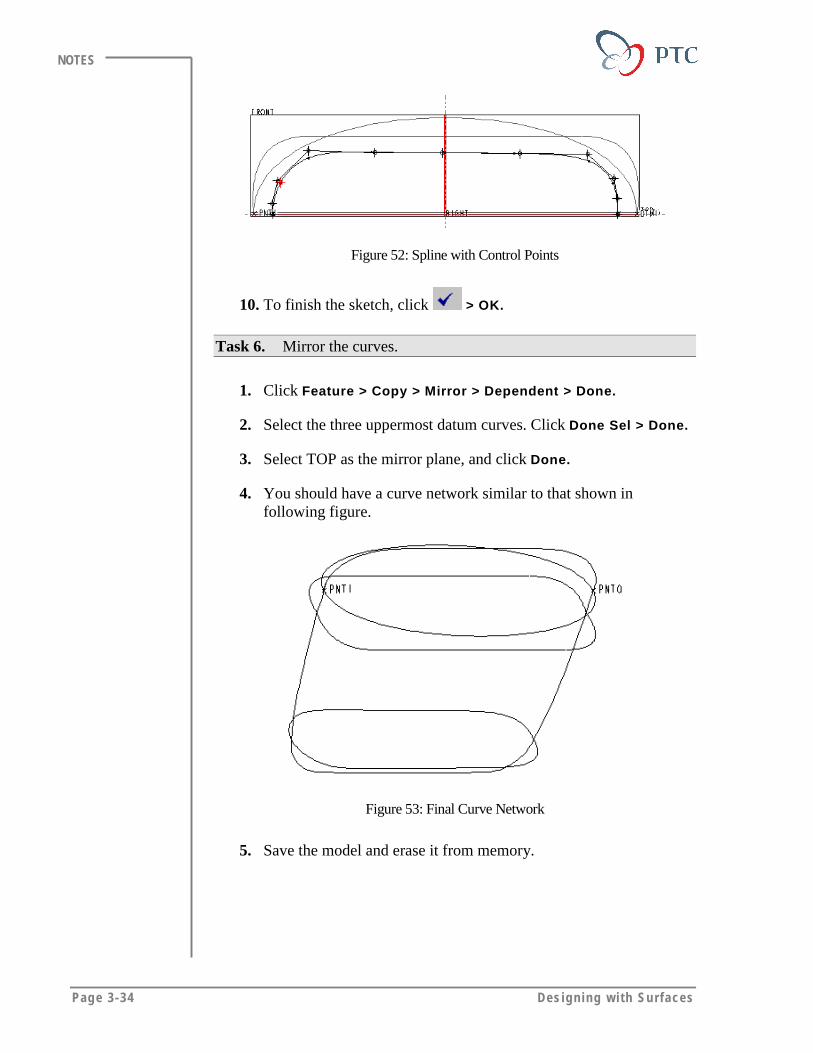
Page 3-34 Des igning w i th Surfaces
NOTES
Figure 52: Spline with Control Points
10. To finish the sketch, click > OK.
Task 6. Mirror the curves.
1. Click Feature > Copy > Mirror > Dependent > Done.
2. Select the three uppermost datum curves. Click Done Sel > Done.
3. Select TOP as the mirror plane, and click Done.
4. You should have a curve network similar to that shown infollowing figure.
Figure 53: Final Curve Network
5. Save the model and erase it from memory.

Geom et ry for Surfaces: Points and Curves Page 3-35
NOTES
MODULE SUMMARYIn this module, you have learned that:
• You can create datum curves using various options.
• Splines can be modified in using several methods.
• Datum points are useful to define and create datum curves.
• You can create datum curves and splines using different options thatare particularly useful while creating surfaces.

Page 4-1
Module
Manipulating SurfacesIn this module you learn to manipulate and join surfaces to create a
quilt.
Objectives
After completing this module, you will be able to:
• Merge surfaces.
• Manipulate the surfaces using the Extend and Trim options.
• Manipulate the location of a surface using the Transform andMove options.
• Create a copy of a surface.

Page 4-2 Des igning w i th Surfaces
NOTES
Pro/ENGINEER enables you to manipulate the surfaces by:
• Extending the surfaces.
• Trimming the surfaces.
• Transforming the surfaces.
• Merging the surfaces.
Extending SurfacesYou can extend the surfaces on a model to avoid gouging a part duringmanufacturing, or to successfully merge surfaces. You create new surfacesby extending the one-sided edges of existing surface features.
Using the following options, you can create the extend feature of a surfaceor an approximate surface along a specified direction, or tangent to itsparent surface:
• Same Srf – Creates the extend feature using the same surface beingextended, continuing the original surface past its original edge by aspecified distance.
Figure 1: Extending Surfaces using the Same Srf Option
• Approx Srf – Creates an extension as a boundary blend. This methodis useful for extending the surface up to a vertex that does not lie alonga straight edge, or for extending imported surfaces that may have beenpoorly created in other systems (for example, when surfaces have highcurvature or bad vertices).
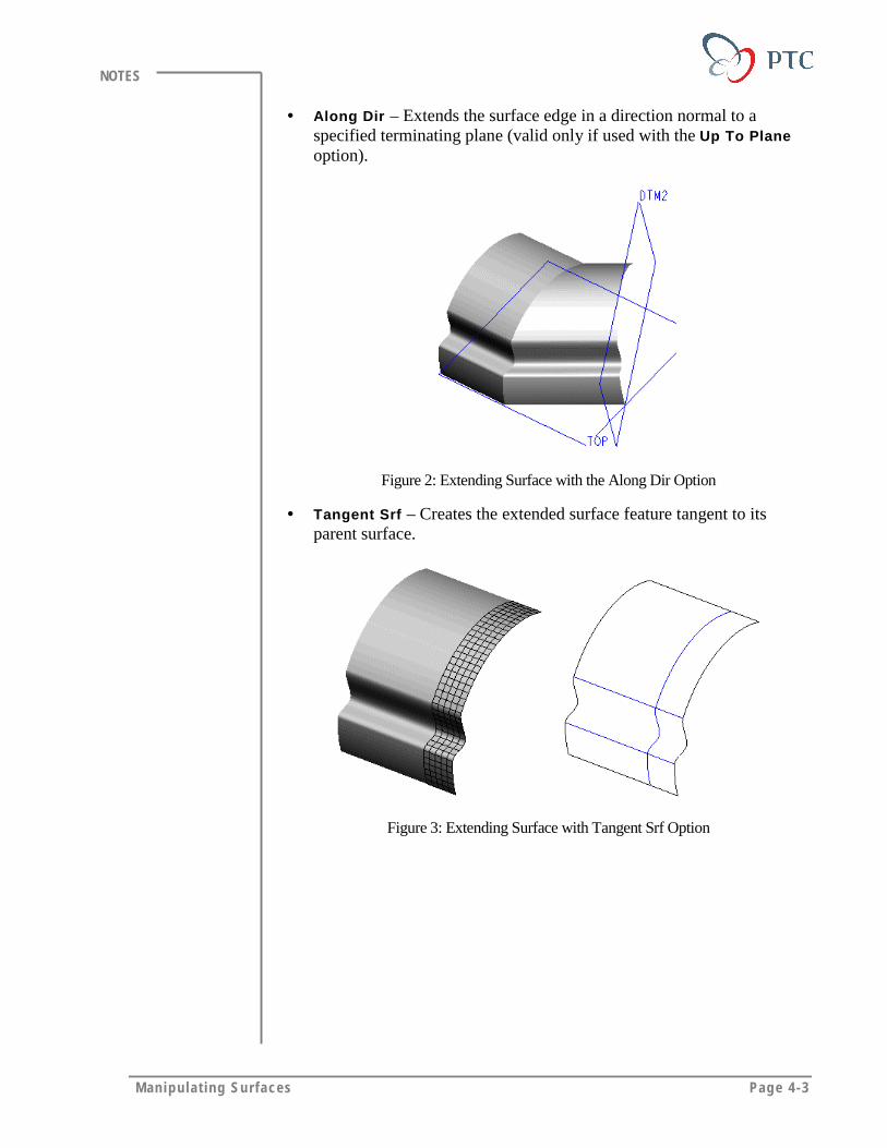
Manipulat ing Surfaces Page 4-3
NOTES
• Along Dir – Extends the surface edge in a direction normal to aspecified terminating plane (valid only if used with the Up To Planeoption).
Figure 2: Extending Surface with the Along Dir Option
• Tangent Srf – Creates the extended surface feature tangent to itsparent surface.
Figure 3: Extending Surface with Tangent Srf Option
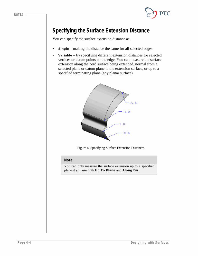
Page 4-4 Des igning w i th Surfaces
NOTES
Specifying the Surface Extension DistanceYou can specify the surface extension distance as:
• Single – making the distance the same for all selected edges.
• Variable – by specifying different extension distances for selectedvertices or datum points on the edge. You can measure the surfaceextension along the cord surface being extended, normal from aselected plane or datum plane to the extension surface, or up to aspecified terminating plane (any planar surface).
Figure 4: Specifying Surface Extension Distances
Note:
You can only measure the surface extension up to a specifiedplane if you use both Up To Plane and Along Dir.
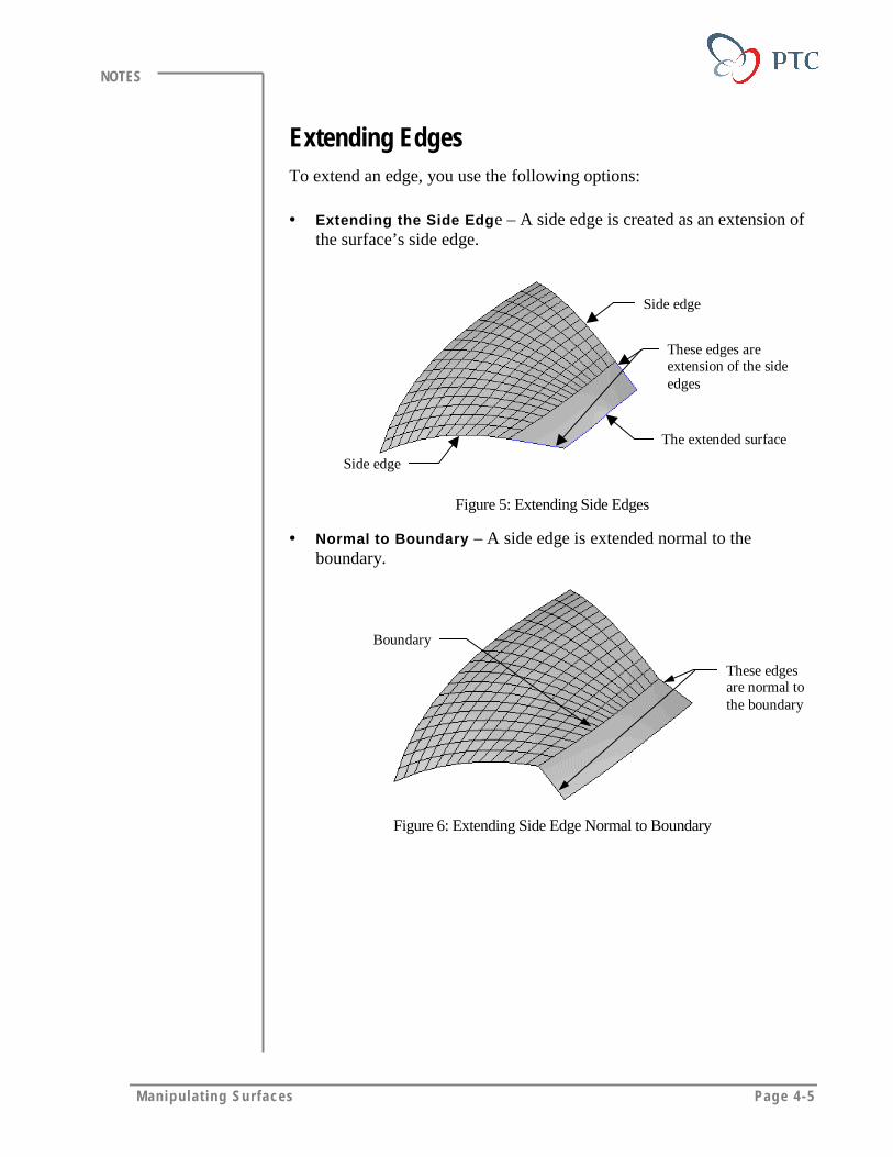
Manipulat ing Surfaces Page 4-5
NOTES
Extending EdgesTo extend an edge, you use the following options:
• Extending the Side Edge – A side edge is created as an extension ofthe surface’s side edge.
The extended surface
Side edge
Side edge
These edges areextension of the sideedges
Figure 5: Extending Side Edges
• Normal to Boundary – A side edge is extended normal to theboundary.
Boundary
These edgesare normal tothe boundary
Figure 6: Extending Side Edge Normal to Boundary

Page 4-6 Des igning w i th Surfaces
NOTES
Trimming SurfacesYou use the trim feature to remove portions of an existing surface feature.A trim feature is similar to a solid cut. You can trim a surface or a quiltusing any of the following feature creation options:
• Extrude, Revolve, Sweep, and Blend – Cuts a piece from an existingsurface feature by creating a sketch and using one of these forms.
• Use Quilts – Cuts a piece from a surface using an intersecting quilt.Pro/ENGINEER consumes the quilt that is used to trim a surface andallows you to keep either or both sides of the trimmed surface, asshown in following figures.
Trimming Quilt
Figure 7: Trimming a Spherical Surface with a Quilt
Figure 8: Two Possible Results of Trimming
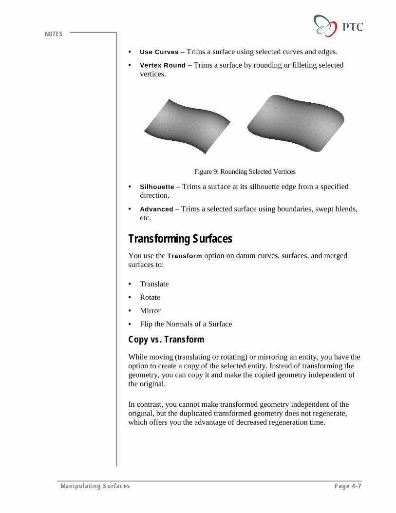
Manipulat ing Surfaces Page 4-7
NOTES
• Use Curves – Trims a surface using selected curves and edges.
• Vertex Round – Trims a surface by rounding or filleting selectedvertices.
Figure 9: Rounding Selected Vertices
• Silhouette – Trims a surface at its silhouette edge from a specifieddirection.
• Advanced – Trims a selected surface using boundaries, swept blends,etc.
Transforming SurfacesYou use the Transform option on datum curves, surfaces, and mergedsurfaces to:
• Translate
• Rotate
• Mirror
• Flip the Normals of a Surface
Copy vs. Transform
While moving (translating or rotating) or mirroring an entity, you have theoption to create a copy of the selected entity. Instead of transforming thegeometry, you can copy it and make the copied geometry independent ofthe original.
In contrast, you cannot make transformed geometry independent of theoriginal, but the duplicated transformed geometry does not regenerate,which offers you the advantage of decreased regeneration time.

Page 4-8 Des igning w i th Surfaces
NOTES
SelectTranslate and
Copy
Select thissurface
Select this coordinate
Figure 10: Transform Option with Translate and Copy
Merging SurfacesYou can merge two adjacent or intersecting quilts. The resulting quilt is aseparate feature, coincident with the two original quilts. There are twooptions you can use to merge the quilts:
• Intersect – Attaches the two intersecting quilts.
• Join – Merges two adjacent quilts by aligning the edges of one quilt tothe surfaces of the other.
Join Intersect
Resultant Merge
Figure 11: Using Merge Join and Merge Intersect
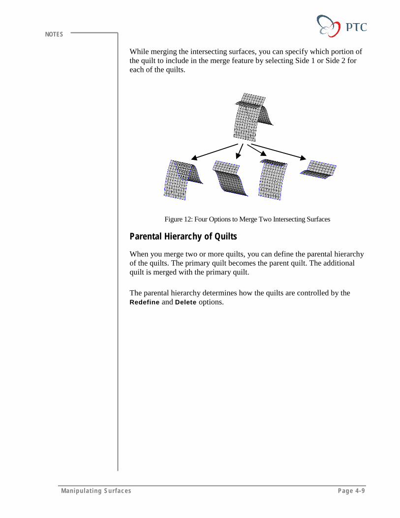
Manipulat ing Surfaces Page 4-9
NOTES
While merging the intersecting surfaces, you can specify which portion ofthe quilt to include in the merge feature by selecting Side 1 or Side 2 foreach of the quilts.
Figure 12: Four Options to Merge Two Intersecting Surfaces
Parental Hierarchy of Quilts
When you merge two or more quilts, you can define the parental hierarchyof the quilts. The primary quilt becomes the parent quilt. The additionalquilt is merged with the primary quilt.
The parental hierarchy determines how the quilts are controlled by theRedefine and Delete options.
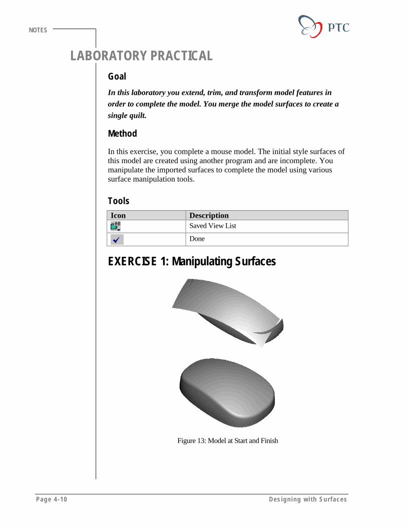
Page 4-10 Des igning w i th Surfaces
NOTES
LABORATORY PRACTICALGoal
In this laboratory you extend, trim, and transform model features in
order to complete the model. You merge the model surfaces to create a
single quilt.
Method
In this exercise, you complete a mouse model. The initial style surfaces ofthis model are created using another program and are incomplete. Youmanipulate the imported surfaces to complete the model using varioussurface manipulation tools.
ToolsIcon Description
Saved View List
Done
EXERCISE 1: Manipulating Surfaces
Figure 13: Model at Start and Finish
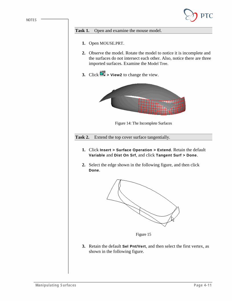
Manipulat ing Surfaces Page 4-11
NOTES
Task 1. Open and examine the mouse model.
1. Open MOUSE.PRT.
2. Observe the model. Rotate the model to notice it is incomplete andthe surfaces do not intersect each other. Also, notice there are threeimported surfaces. Examine the Model Tree.
3. Click > View2 to change the view.
Figure 14: The Incomplete Surfaces
Task 2. Extend the top cover surface tangentially.
1. Click Insert > Surface Operation > Extend. Retain the defaultVariable and Dist On Srf, and click Tangent Surf > Done.
2. Select the edge shown in the following figure, and then clickDone.
Figure 15
3. Retain the default Sel Pnt/Vert, and then select the first vertex, asshown in the following figure.
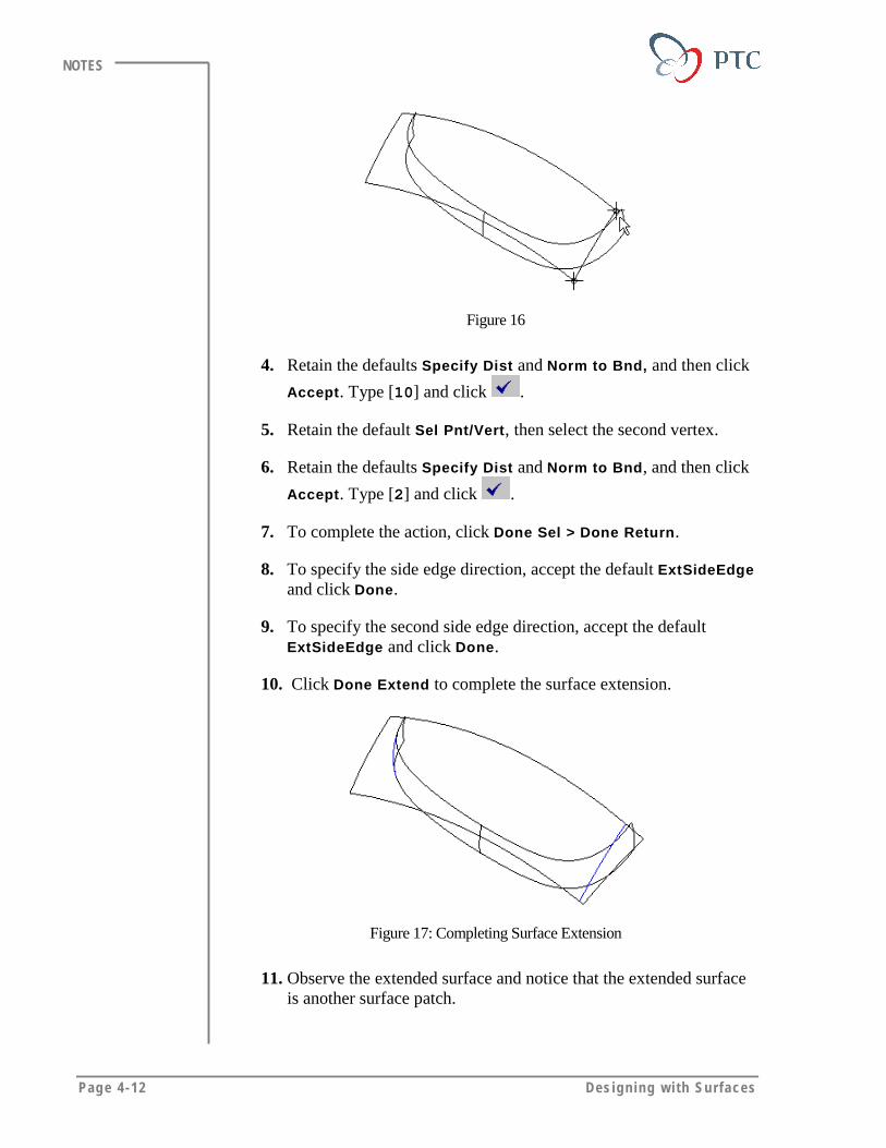
Page 4-12 Des igning w i th Surfaces
NOTES
Figure 16
4. Retain the defaults Specify Dist and Norm to Bnd, and then click
Accept. Type [10] and click .
5. Retain the default Sel Pnt/Vert, then select the second vertex.
6. Retain the defaults Specify Dist and Norm to Bnd, and then click
Accept. Type [2] and click .
7. To complete the action, click Done Sel > Done Return.
8. To specify the side edge direction, accept the default ExtSideEdgeand click Done.
9. To specify the second side edge direction, accept the defaultExtSideEdge and click Done.
10. Click Done Extend to complete the surface extension.
Figure 17: Completing Surface Extension
11. Observe the extended surface and notice that the extended surfaceis another surface patch.
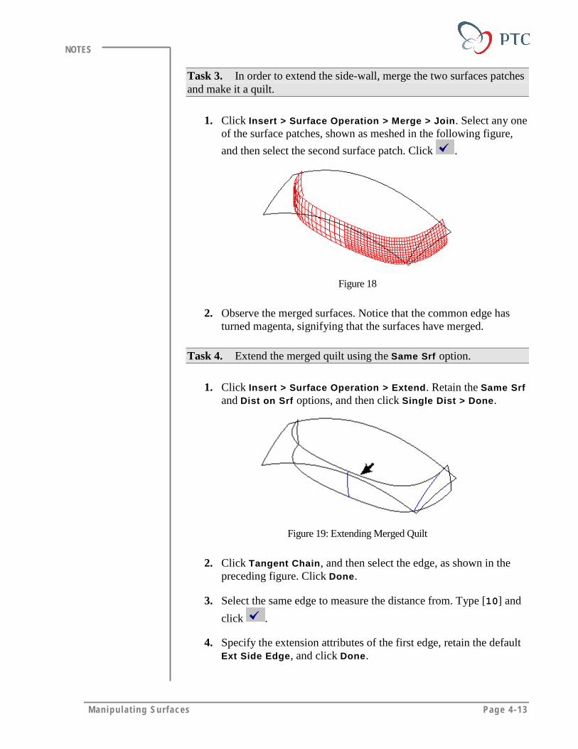
Manipulat ing Surfaces Page 4-13
NOTES
Task 3. In order to extend the side-wall, merge the two surfaces patchesand make it a quilt.
1. Click Insert > Surface Operation > Merge > Join. Select any oneof the surface patches, shown as meshed in the following figure,
and then select the second surface patch. Click .
Figure 18
2. Observe the merged surfaces. Notice that the common edge hasturned magenta, signifying that the surfaces have merged.
Task 4. Extend the merged quilt using the Same Srf option.
1. Click Insert > Surface Operation > Extend. Retain the Same Srfand Dist on Srf options, and then click Single Dist > Done.
Figure 19: Extending Merged Quilt
2. Click Tangent Chain, and then select the edge, as shown in thepreceding figure. Click Done.
3. Select the same edge to measure the distance from. Type [10] and
click .
4. Specify the extension attributes of the first edge, retain the defaultExt Side Edge, and click Done.

Page 4-14 Des igning w i th Surfaces
NOTES
5. Specify the extension attributes of the other edge, retain the defaultExt Side Edge, and click Done.
6. Complete the surface extension. Click Done Extend.
Figure 20
7. Observe the model. Notice that the Same Srf option does notcreate a separate patch while extending a surface.
Task 5. To accommodate a design change in the internal packaging,move the side wall surface away from the mid-plane.
1. Move the surface. Click Insert > Surface Operation > Transform> Move > No Copy > Done. Select the side wall surface, and thenclick Done Sel.
2. Click Translate, and then select the TOP datum plane.
Figure 21
3. Click Okay to accept the default direction, as shown in thepreceding figure.
4. Define the translation value. Type [3], and then click .
5. Click Done Move to finish the translation.

Manipulat ing Surfaces Page 4-15
NOTES
6. Observe the model to notice the gap generated because oftranslation.
Figure 22
Task 6. Extend the side wall edges to the mid- plane so that there is nogap when you mirror the model.
1. Extend the first edge of the surface. Click Insert > SurfaceOperation > Extend > Along Dir > Done. Select the edge shownin the following figure, and then click Done Sel > Done.
Figure 23
2. Select the TOP datum plane, and then click Done Extend to definethe plane.
3. Extend the other edge using the method outlined in previous steps.
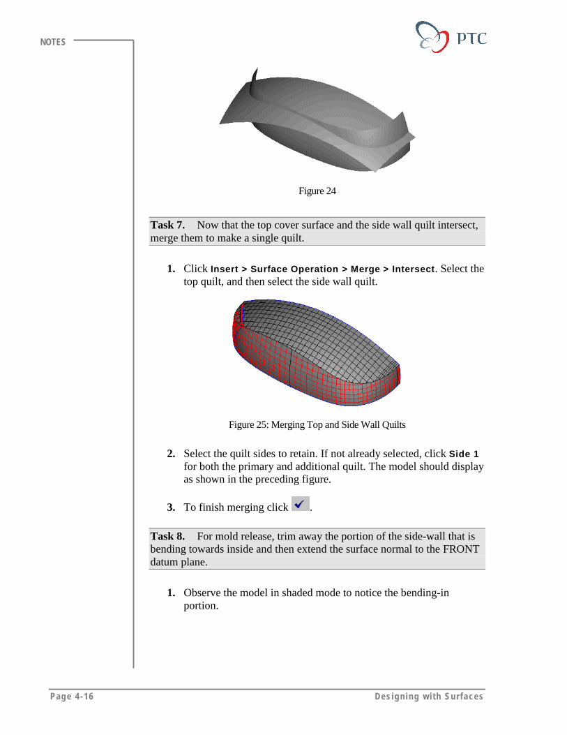
Page 4-16 Des igning w i th Surfaces
NOTES
Figure 24
Task 7. Now that the top cover surface and the side wall quilt intersect,merge them to make a single quilt.
1. Click Insert > Surface Operation > Merge > Intersect. Select thetop quilt, and then select the side wall quilt.
Figure 25: Merging Top and Side Wall Quilts
2. Select the quilt sides to retain. If not already selected, click Side 1for both the primary and additional quilt. The model should displayas shown in the preceding figure.
3. To finish merging click .
Task 8. For mold release, trim away the portion of the side-wall that isbending towards inside and then extend the surface normal to the FRONTdatum plane.
1. Observe the model in shaded mode to notice the bending-inportion.

Manipulat ing Surfaces Page 4-17
NOTES
Figure 26:
2. Trim away the bending-in portion. Click Insert > Surface Trim >Silhouette > Done.
3. Select the side-wall quilt.
4. To define the viewing plane, select the FRONT datum plane.
Figure 27
5. Click Side1 > Done to select the side to retain.
6. Click Preview to see how the surface is being trimmed, and thenclick OK to finish creating the feature.
7. Extend the trimmed edge up to the FRONT datum plane using themethod outlined in the previous steps.
Figure 28
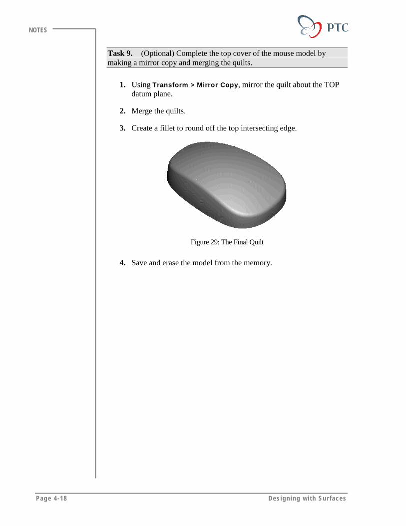
Page 4-18 Des igning w i th Surfaces
NOTES
Task 9. (Optional) Complete the top cover of the mouse model bymaking a mirror copy and merging the quilts.
1. Using Transform > Mirror Copy, mirror the quilt about the TOPdatum plane.
2. Merge the quilts.
3. Create a fillet to round off the top intersecting edge.
Figure 29: The Final Quilt
4. Save and erase the model from the memory.

Manipulat ing Surfaces Page 4-19
NOTES
MODULE SUMMARYIn this module, you have learned that:
• You can extend or trim Pro/ENGINNER surface features or importedsurfaces in order to manipulate their size and shape.
• You can translate or rotate a surface feature using the Transformoption.
• You can mirror a surface feature about plane using the Mirror option.
• While you transform a surface, you can transform the base geometryitself or create a copy of it.
• You can merge adjacent or intersecting surfaces to create a quilt.


Page 5-1
Module
Modifying Solid Surfaces Using QuiltsIn this module you learn how to use quilts in order to manipulate
and define the complex shapes of the solid features.
Objectives
After completing this module, you will be able to:
• Define and create Surface Replace features.
• Define Surface Patch features.
• Define and create a cut in a solid object using a quilt.

Page 5-2 Des igning w i th Surfaces
NOTES
USING QUILTS TO MANIPULATE SOLIDSThere are many ways you can use quilts to manipulate the solid geometry.You can:
• Replace a solid surface with a quilt.
• Create a Patch feature.
• Create Cuts using quilts.
REPLACING SURFACESYou can replace a solid surface with a datum plane or a quilt.
Figure 1: Replacing A Solid Surface with a Quilt
Keeping the Quilt
By default, when you replace a solid surface by a quilt, the quilt isconsumed. If you want to retain the quilt, you can select Keep Quilt.
Restrictions and Requirements of Replace
• If surface replacement adds material in some places and removes it inothers, then the replacing quilt must consist of one surface only.
• It is not recommended to create two replacement features on top ofeach other. It is a good practice to delete one replacement quilt beforecreating a new one, or to redefine the existing replace feature so itreplaces a different surface or uses a different quilt.

Modi fy ing So l id Surfaces Using Qui l t s Page 5-3
NOTES
• For correct surface replacement, make sure the quilt extends to orbeyond the part boundaries. If this requirement is not met,Pro/ENGINEER will attempt to extend the quilt to intersect the partboundaries as shown in the following figure.
Figure 2
PATCHINGWith patching, you can replace a portion of a surface or multiple surfaceswith a single quilt, as shown in the following figure. The Patch optionallows you to add and remove material in a single operation. To create apatch feature, all the boundaries of the replacement quilt must lie on thesurfaces being patched.
SolidA surface lying on thethree solid surfaces
Resulting solid from the Patchoperation
Figure 3
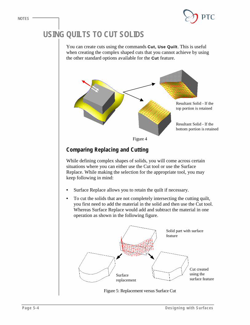
Page 5-4 Des igning w i th Surfaces
NOTES
USING QUILTS TO CUT SOLIDSYou can create cuts using the commands Cut, Use Quilt. This is usefulwhen creating the complex shaped cuts that you cannot achieve by usingthe other standard options available for the Cut feature.
Resultant Solid - If thetop portion is retained
Resultant Solid - If thebottom portion is retained
Figure 4
Comparing Replacing and Cutting
While defining complex shapes of solids, you will come across certainsituations where you can either use the Cut tool or use the SurfaceReplace. While making the selection for the appropriate tool, you maykeep following in mind:
• Surface Replace allows you to retain the quilt if necessary.
• To cut the solids that are not completely intersecting the cutting quilt,you first need to add the material in the solid and then use the Cut tool.Whereas Surface Replace would add and subtract the material in oneoperation as shown in the following figure.
Solid part with surfacefeature
Cut createdusing thesurface feature
Surfacereplacement
Figure 5: Replacement versus Surface Cut

Modi fy ing So l id Surfaces Using Qui l t s Page 5-5
NOTES
LABORATORY PRACTICALGoal
In this laboratory, you will manipulate the shape of the solid features
using the Replace and Cut features.
Method
In the first exercise, you use the replace functionality to force a stiffener tofollow a complicated fuselage shape. You also use the replacefunctionality to create a rib feature that follows the shape of the surfacefeatures.
In the second exercise, you create a quilt then cut the solid using the quilt.
ToolsIcon Description
Saved View List
Build Feature
Done
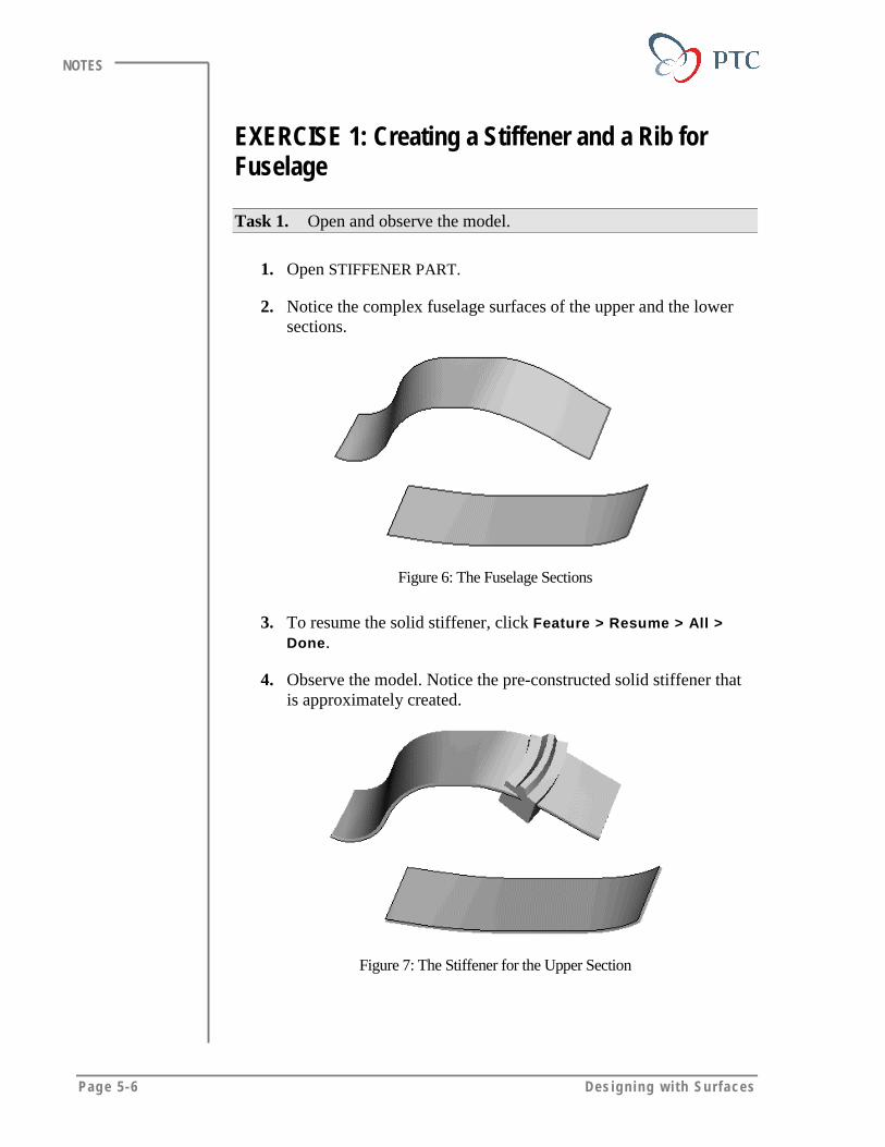
Page 5-6 Des igning w i th Surfaces
NOTES
EXERCISE 1: Creating a Stiffener and a Rib forFuselage
Task 1. Open and observe the model.
1. Open STIFFENER PART.
2. Notice the complex fuselage surfaces of the upper and the lowersections.
Figure 6: The Fuselage Sections
3. To resume the solid stiffener, click Feature > Resume > All >Done.
4. Observe the model. Notice the pre-constructed solid stiffener thatis approximately created.
Figure 7: The Stiffener for the Upper Section
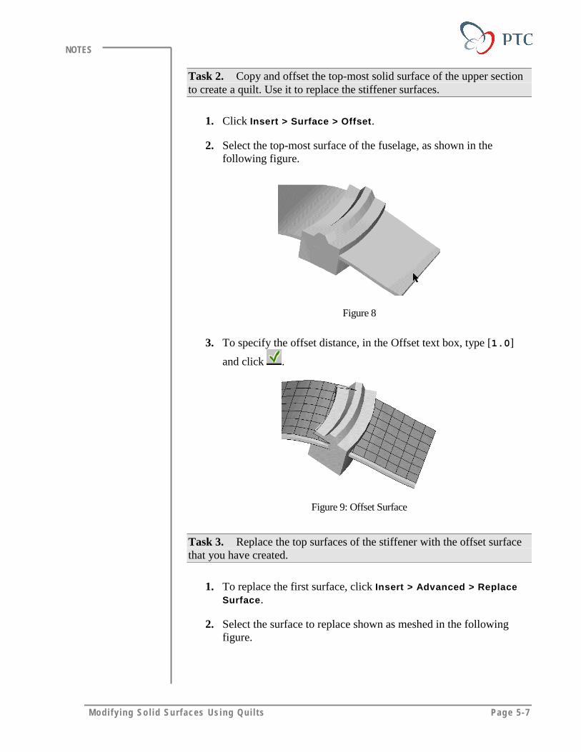
Modi fy ing So l id Surfaces Using Qui l t s Page 5-7
NOTES
Task 2. Copy and offset the top-most solid surface of the upper sectionto create a quilt. Use it to replace the stiffener surfaces.
1. Click Insert > Surface > Offset.
2. Select the top-most surface of the fuselage, as shown in thefollowing figure.
Figure 8
3. To specify the offset distance, in the Offset text box, type [1.0]
and click .
Figure 9: Offset Surface
Task 3. Replace the top surfaces of the stiffener with the offset surfacethat you have created.
1. To replace the first surface, click Insert > Advanced > ReplaceSurface.
2. Select the surface to replace shown as meshed in the followingfigure.
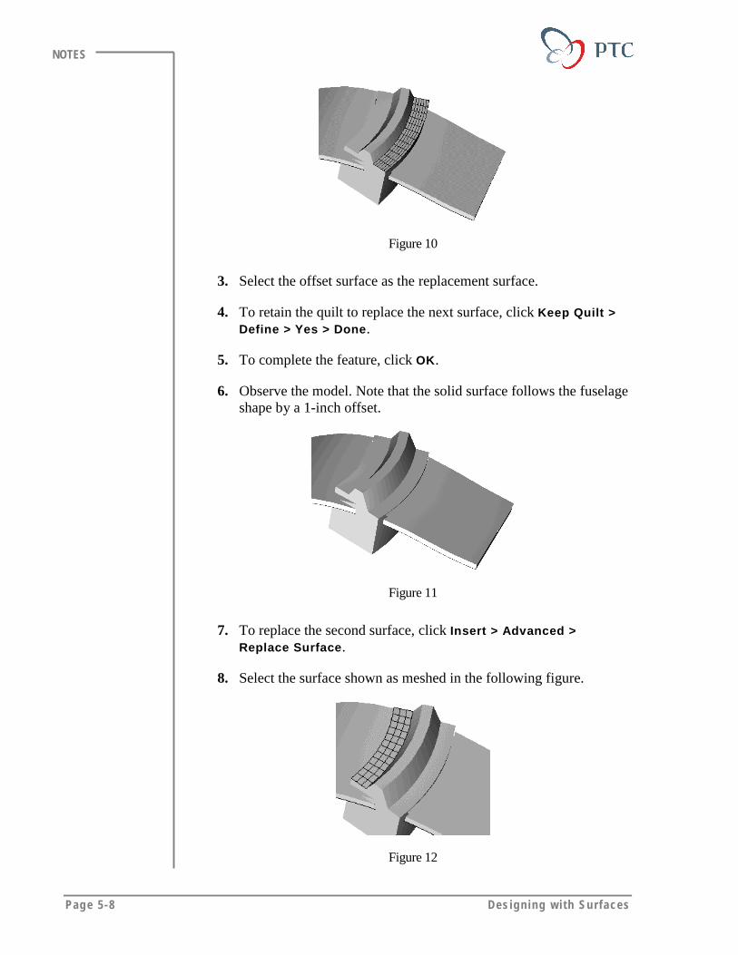
Page 5-8 Des igning w i th Surfaces
NOTES
Figure 10
3. Select the offset surface as the replacement surface.
4. To retain the quilt to replace the next surface, click Keep Quilt >Define > Yes > Done.
5. To complete the feature, click OK.
6. Observe the model. Note that the solid surface follows the fuselageshape by a 1-inch offset.
Figure 11
7. To replace the second surface, click Insert > Advanced >Replace Surface.
8. Select the surface shown as meshed in the following figure.
Figure 12
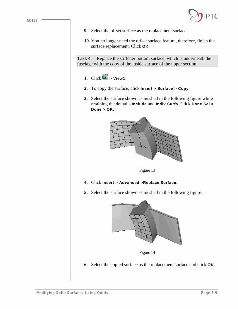
Modi fy ing So l id Surfaces Using Qui l t s Page 5-9
NOTES
9. Select the offset surface as the replacement surface.
10. You no longer need the offset surface feature, therefore, finish thesurface replacement. Click OK.
Task 4. Replace the stiffener bottom surface, which is underneath thefuselage with the copy of the inside surface of the upper section.
1. Click > View1.
2. To copy the surface, click Insert > Surface > Copy.
3. Select the surface shown as meshed in the following figure whileretaining the defaults Include and Indiv Surfs. Click Done Sel >Done > OK.
Figure 13
4. Click Insert > Advanced >Replace Surface.
5. Select the surface shown as meshed in the following figure.
Figure 14
6. Select the copied surface as the replacement surface and click OK.
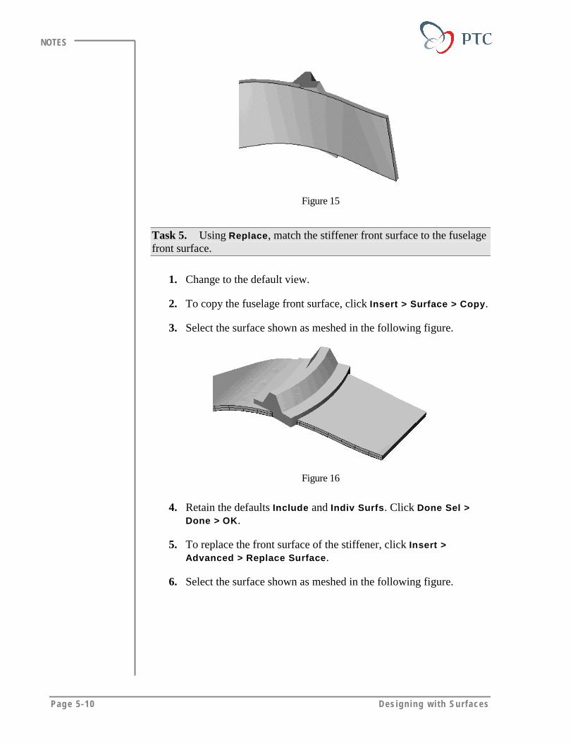
Page 5-10 Des igning w i th Surfaces
NOTES
Figure 15
Task 5. Using Replace, match the stiffener front surface to the fuselagefront surface.
1. Change to the default view.
2. To copy the fuselage front surface, click Insert > Surface > Copy.
3. Select the surface shown as meshed in the following figure.
Figure 16
4. Retain the defaults Include and Indiv Surfs. Click Done Sel >Done > OK.
5. To replace the front surface of the stiffener, click Insert >Advanced > Replace Surface.
6. Select the surface shown as meshed in the following figure.
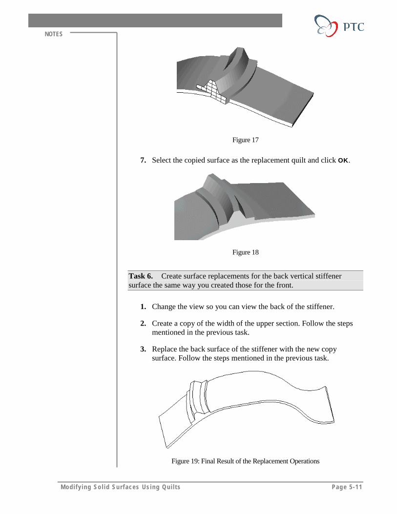
Modi fy ing So l id Surfaces Using Qui l t s Page 5-11
NOTES
Figure 17
7. Select the copied surface as the replacement quilt and click OK.
Figure 18
Task 6. Create surface replacements for the back vertical stiffenersurface the same way you created those for the front.
1. Change the view so you can view the back of the stiffener.
2. Create a copy of the width of the upper section. Follow the stepsmentioned in the previous task.
3. Replace the back surface of the stiffener with the new copysurface. Follow the steps mentioned in the previous task.
Figure 19: Final Result of the Replacement Operations
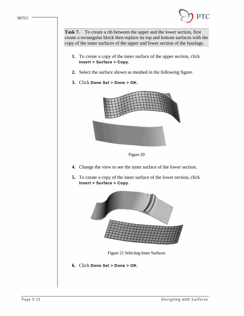
Page 5-12 Des igning w i th Surfaces
NOTES
Task 7. To create a rib between the upper and the lower section, firstcreate a rectangular block then replace its top and bottom surfaces with thecopy of the inner surfaces of the upper and lower section of the fuselage.
1. To create a copy of the inner surface of the upper section, clickInsert > Surface > Copy.
2. Select the surface shown as meshed in the following figure.
3. Click Done Sel > Done > OK.
Figure 20
4. Change the view to see the inner surface of the lower section.
5. To create a copy of the inner surface of the lower section, clickInsert > Surface > Copy.
Figure 21 Selecting Inner Surfaces
6. Click Done Sel > Done > OK.
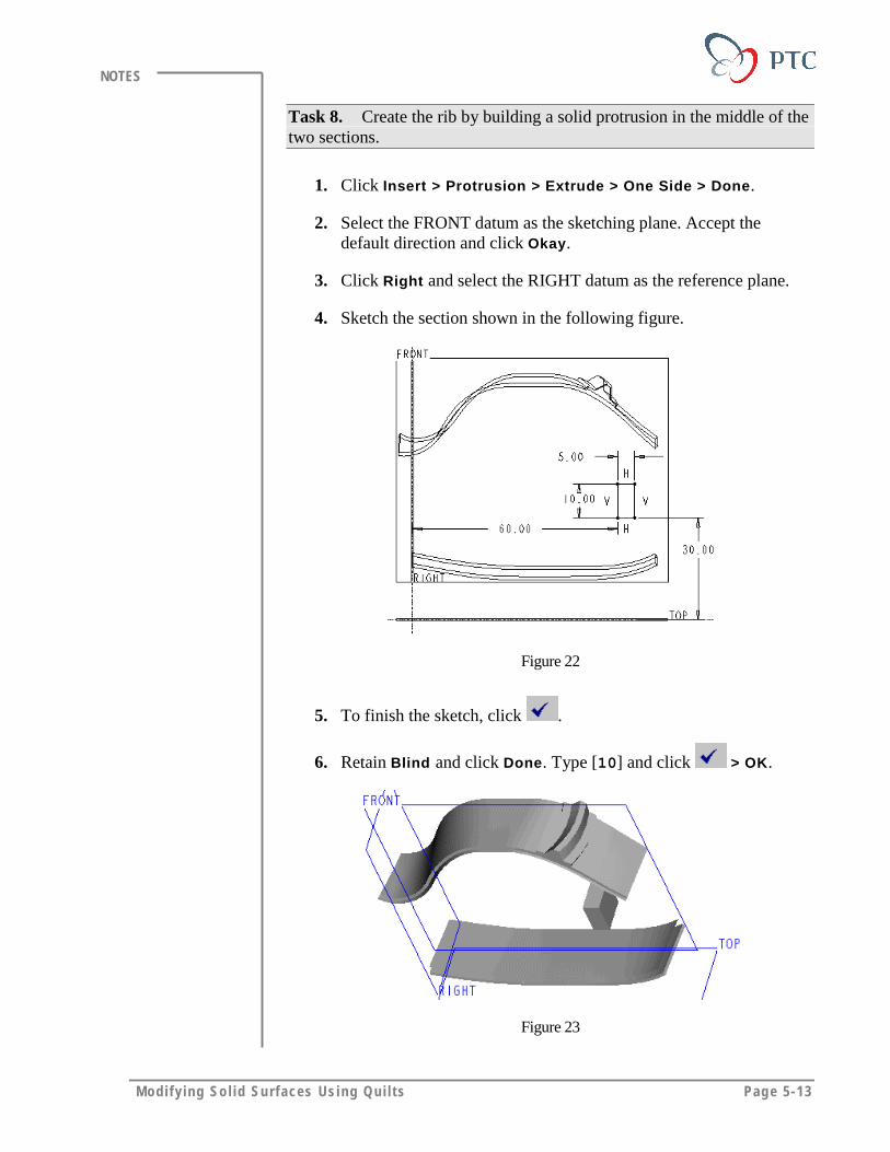
Modi fy ing So l id Surfaces Using Qui l t s Page 5-13
NOTES
Task 8. Create the rib by building a solid protrusion in the middle of thetwo sections.
1. Click Insert > Protrusion > Extrude > One Side > Done.
2. Select the FRONT datum as the sketching plane. Accept thedefault direction and click Okay.
3. Click Right and select the RIGHT datum as the reference plane.
4. Sketch the section shown in the following figure.
Figure 22
5. To finish the sketch, click .
6. Retain Blind and click Done. Type [10] and click > OK.
Figure 23
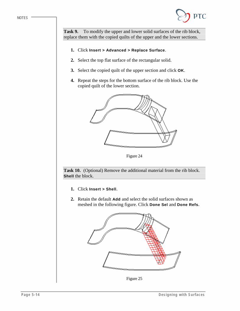
Page 5-14 Des igning w i th Surfaces
NOTES
Task 9. To modify the upper and lower solid surfaces of the rib block,replace them with the copied quilts of the upper and the lower sections.
1. Click Insert > Advanced > Replace Surface.
2. Select the top flat surface of the rectangular solid.
3. Select the copied quilt of the upper section and click OK.
4. Repeat the steps for the bottom surface of the rib block. Use thecopied quilt of the lower section.
Figure 24
Task 10. (Optional) Remove the additional material from the rib block.Shell the block.
1. Click Insert > Shell.
2. Retain the default Add and select the solid surfaces shown asmeshed in the following figure. Click Done Sel and Done Refs.
Figure 25
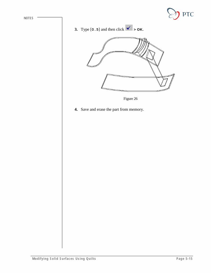
Modi fy ing So l id Surfaces Using Qui l t s Page 5-15
NOTES
3. Type [0.5] and then click > OK.
Figure 26
4. Save and erase the part from memory.
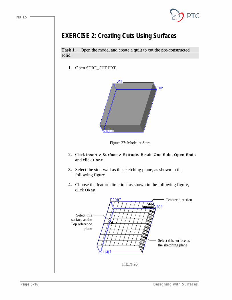
Page 5-16 Des igning w i th Surfaces
NOTES
EXERCISE 2: Creating Cuts Using Surfaces
Task 1. Open the model and create a quilt to cut the pre-constructedsolid.
1. Open SURF_CUT.PRT.
Figure 27: Model at Start
2. Click Insert > Surface > Extrude. Retain One Side, Open Endsand click Done.
3. Select the side-wall as the sketching plane, as shown in thefollowing figure.
4. Choose the feature direction, as shown in the following figure,click Okay.
Select this surface asthe sketching plane
Select thissurface as theTop reference
plane
Feature direction
Figure 28
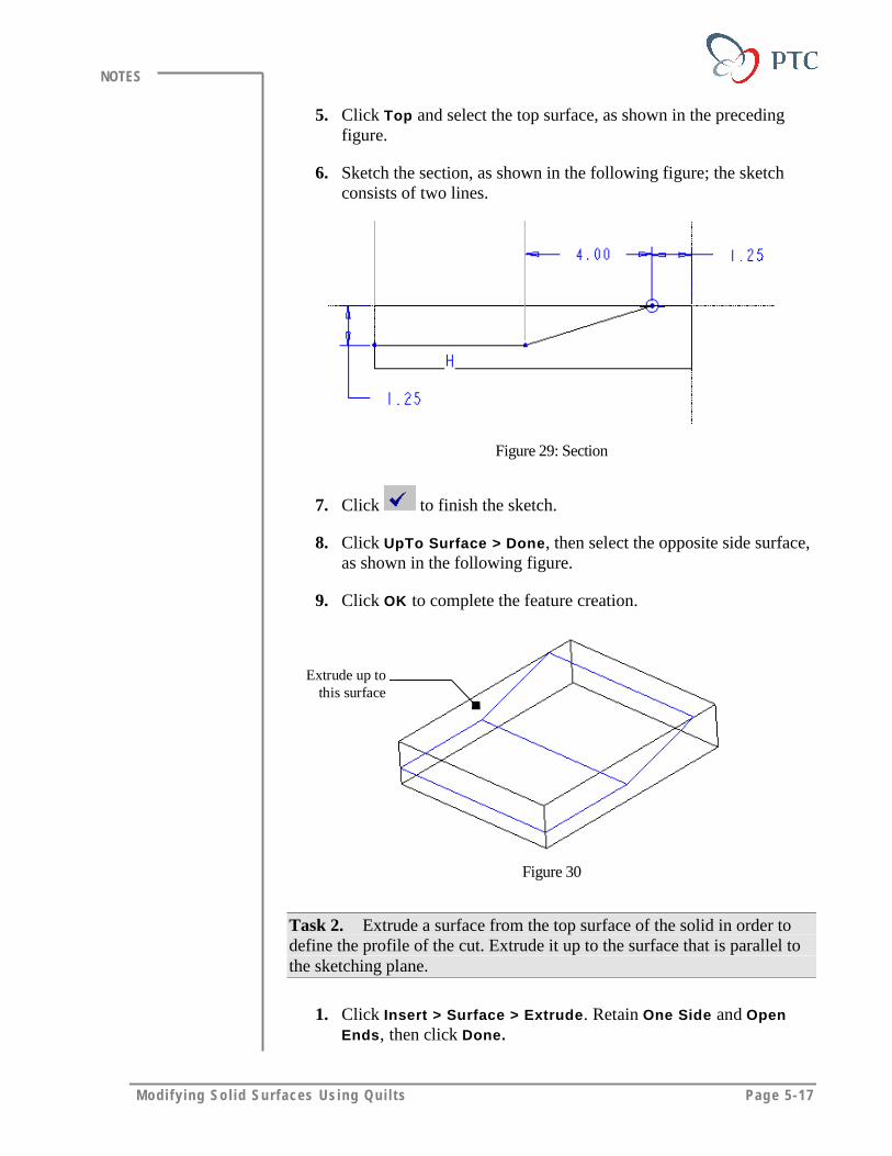
Modi fy ing So l id Surfaces Using Qui l t s Page 5-17
NOTES
5. Click Top and select the top surface, as shown in the precedingfigure.
6. Sketch the section, as shown in the following figure; the sketchconsists of two lines.
Figure 29: Section
7. Click to finish the sketch.
8. Click UpTo Surface > Done, then select the opposite side surface,as shown in the following figure.
9. Click OK to complete the feature creation.
Extrude up tothis surface
Figure 30
Task 2. Extrude a surface from the top surface of the solid in order todefine the profile of the cut. Extrude it up to the surface that is parallel tothe sketching plane.
1. Click Insert > Surface > Extrude. Retain One Side and OpenEnds, then click Done.
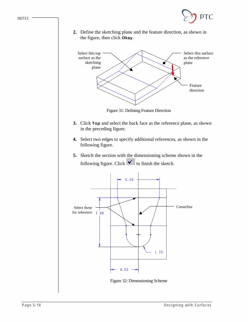
Page 5-18 Des igning w i th Surfaces
NOTES
2. Define the sketching plane and the feature direction, as shown inthe figure, then click Okay.
Select this surfaceas the referenceplane
Select this topsurface as the
sketchingplane
Featuredirection
Figure 31: Defining Feature Direction
3. Click Top and select the back face as the reference plane, as shownin the preceding figure.
4. Select two edges to specify additional references, as shown in thefollowing figure.
5. Sketch the section with the dimensioning scheme shown in the
following figure. Click to finish the sketch.
Select thesefor reference
Centerline
Figure 32: Dimensioning Scheme
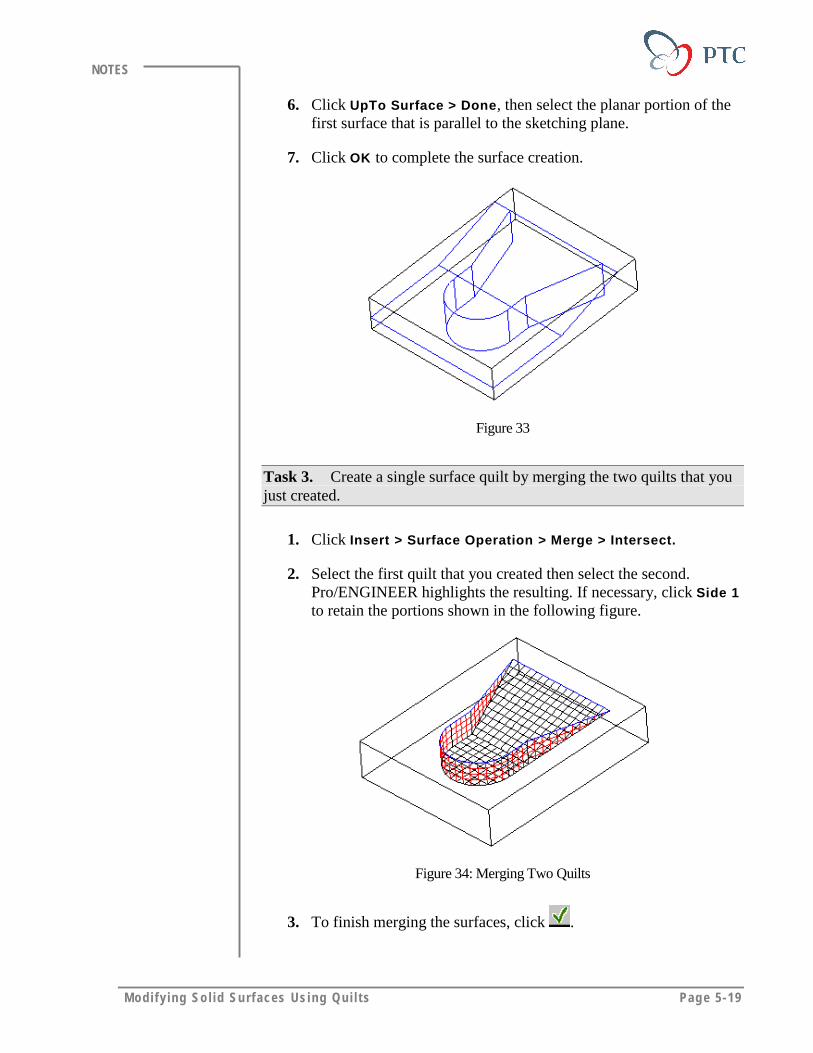
Modi fy ing So l id Surfaces Using Qui l t s Page 5-19
NOTES
6. Click UpTo Surface > Done, then select the planar portion of thefirst surface that is parallel to the sketching plane.
7. Click OK to complete the surface creation.
Figure 33
Task 3. Create a single surface quilt by merging the two quilts that youjust created.
1. Click Insert > Surface Operation > Merge > Intersect.
2. Select the first quilt that you created then select the second.Pro/ENGINEER highlights the resulting. If necessary, click Side 1to retain the portions shown in the following figure.
Figure 34: Merging Two Quilts
3. To finish merging the surfaces, click .
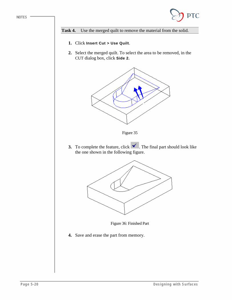
Page 5-20 Des igning w i th Surfaces
NOTES
Task 4. Use the merged quilt to remove the material from the solid.
1. Click Insert Cut > Use Quilt.
2. Select the merged quilt. To select the area to be removed, in theCUT dialog box, click Side 2.
Figure 35
3. To complete the feature, click . The final part should look likethe one shown in the following figure.
Figure 36: Finished Part
4. Save and erase the part from memory.
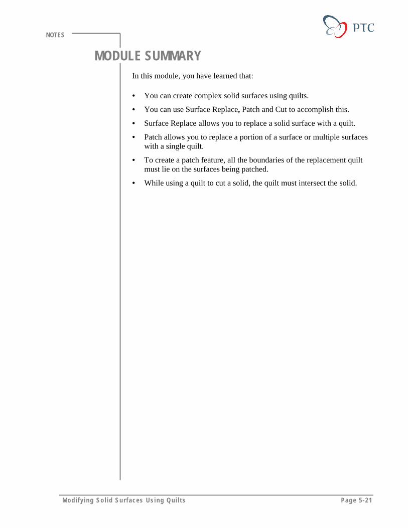
Modi fy ing So l id Surfaces Using Qui l t s Page 5-21
NOTES
MODULE SUMMARYIn this module, you have learned that:
• You can create complex solid surfaces using quilts.
• You can use Surface Replace, Patch and Cut to accomplish this.
• Surface Replace allows you to replace a solid surface with a quilt.
• Patch allows you to replace a portion of a surface or multiple surfaceswith a single quilt.
• To create a patch feature, all the boundaries of the replacement quiltmust lie on the surfaces being patched.
• While using a quilt to cut a solid, the quilt must intersect the solid.

Page 6-1
Module
Creating Solids Using QuiltsIn this module you learn how to create solids from surfaces or quilts.
Objectives
After completing this module, you will be able to:
• Create a thin feature using open quilts.
• Create a solid feature using closed quilts.
• Create a solid feature using open quilts that intersect with solids.
• Create offset features using different options.
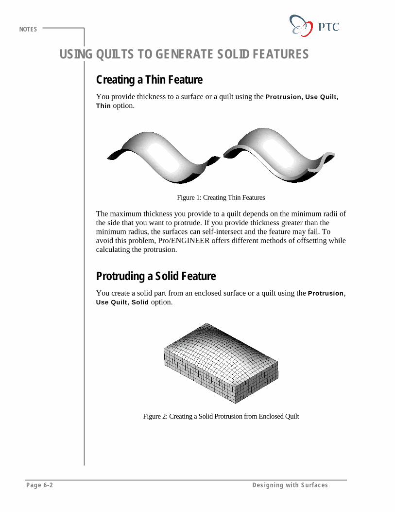
Page 6-2 Des igning w i th Surfaces
NOTES
USING QUILTS TO GENERATE SOLID FEATURES
Creating a Thin FeatureYou provide thickness to a surface or a quilt using the Protrusion, Use Quilt,Thin option.
Figure 1: Creating Thin Features
The maximum thickness you provide to a quilt depends on the minimum radii ofthe side that you want to protrude. If you provide thickness greater than theminimum radius, the surfaces can self-intersect and the feature may fail. Toavoid this problem, Pro/ENGINEER offers different methods of offsetting whilecalculating the protrusion.
Protruding a Solid FeatureYou create a solid part from an enclosed surface or a quilt using the Protrusion,Use Quilt, Solid option.
Figure 2: Creating a Solid Protrusion from Enclosed Quilt
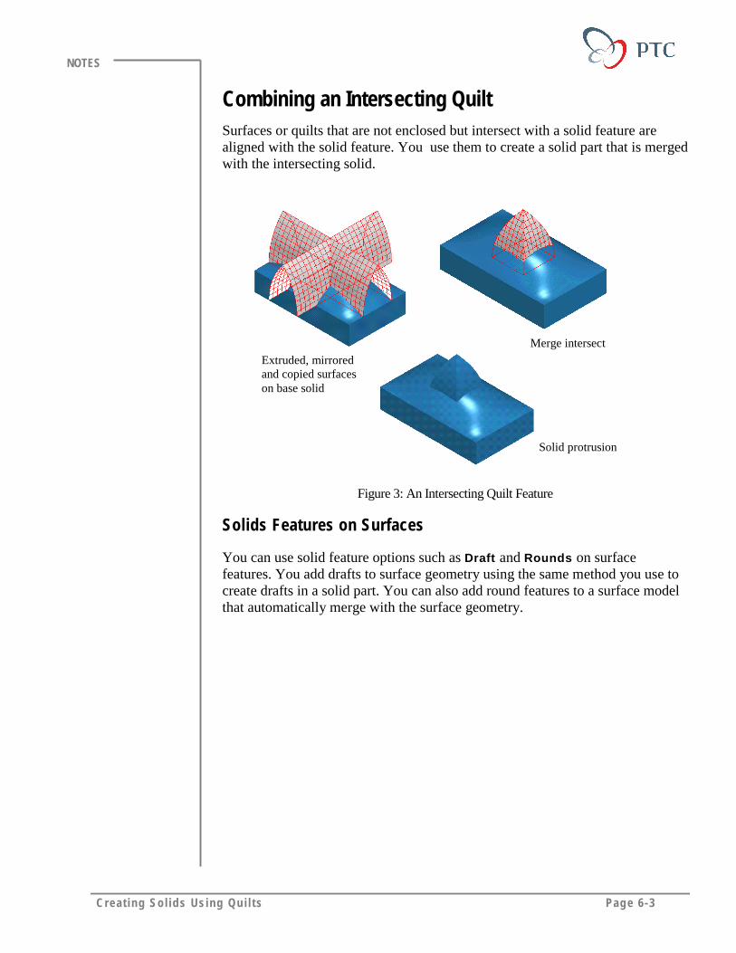
Creat ing Sol ids Using Qu i l ts Page 6-3
NOTES
Combining an Intersecting QuiltSurfaces or quilts that are not enclosed but intersect with a solid feature arealigned with the solid feature. You use them to create a solid part that is mergedwith the intersecting solid.
Extruded, mirroredand copied surfaceson base solid
Solid protrusion
Merge intersect
Figure 3: An Intersecting Quilt Feature
Solids Features on Surfaces
You can use solid feature options such as Draft and Rounds on surfacefeatures. You add drafts to surface geometry using the same method you use tocreate drafts in a solid part. You can also add round features to a surface modelthat automatically merge with the surface geometry.
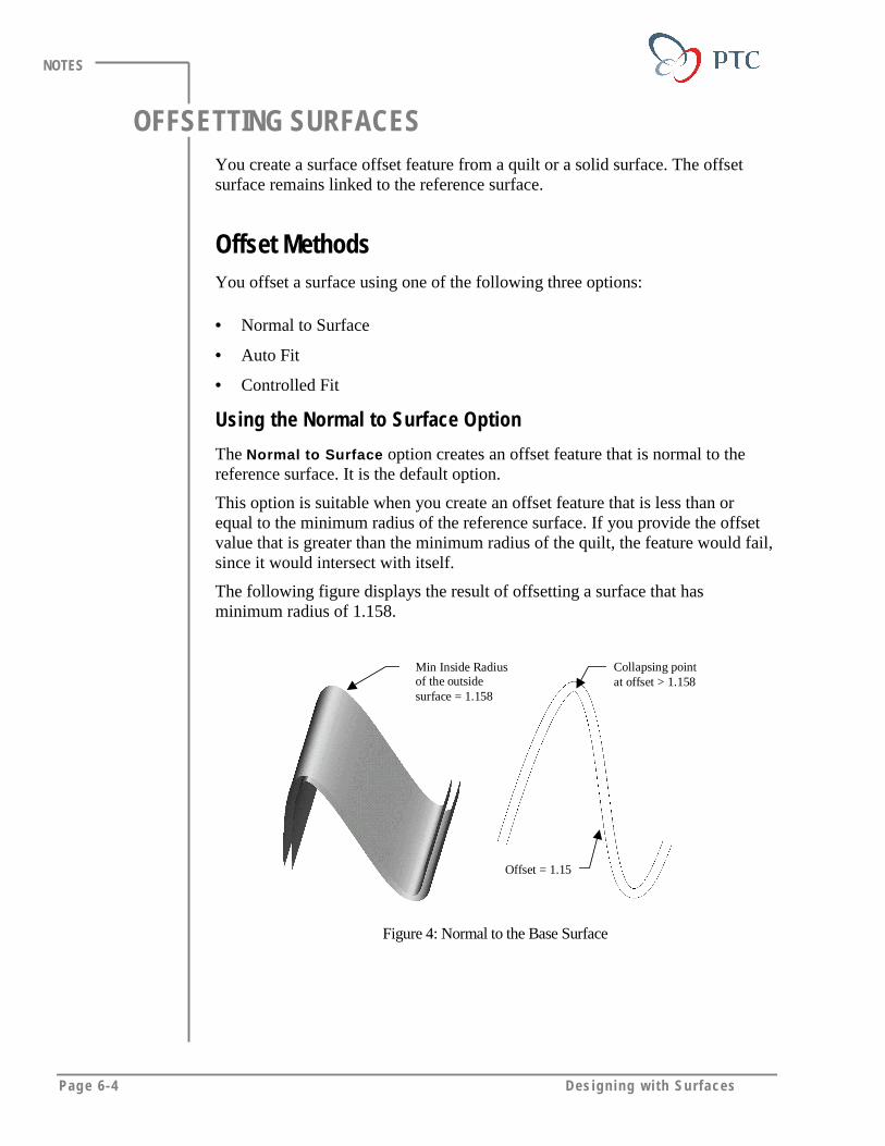
Page 6-4 Des igning w i th Surfaces
NOTES
OFFSETTING SURFACESYou create a surface offset feature from a quilt or a solid surface. The offsetsurface remains linked to the reference surface.
Offset MethodsYou offset a surface using one of the following three options:
• Normal to Surface
• Auto Fit
• Controlled Fit
Using the Normal to Surface Option
The Normal to Surface option creates an offset feature that is normal to thereference surface. It is the default option.
This option is suitable when you create an offset feature that is less than orequal to the minimum radius of the reference surface. If you provide the offsetvalue that is greater than the minimum radius of the quilt, the feature would fail,since it would intersect with itself.
The following figure displays the result of offsetting a surface that hasminimum radius of 1.158.
Min Inside Radiusof the outsidesurface = 1.158
Collapsing pointat offset > 1.158
Offset = 1.15
Figure 4: Normal to the Base Surface
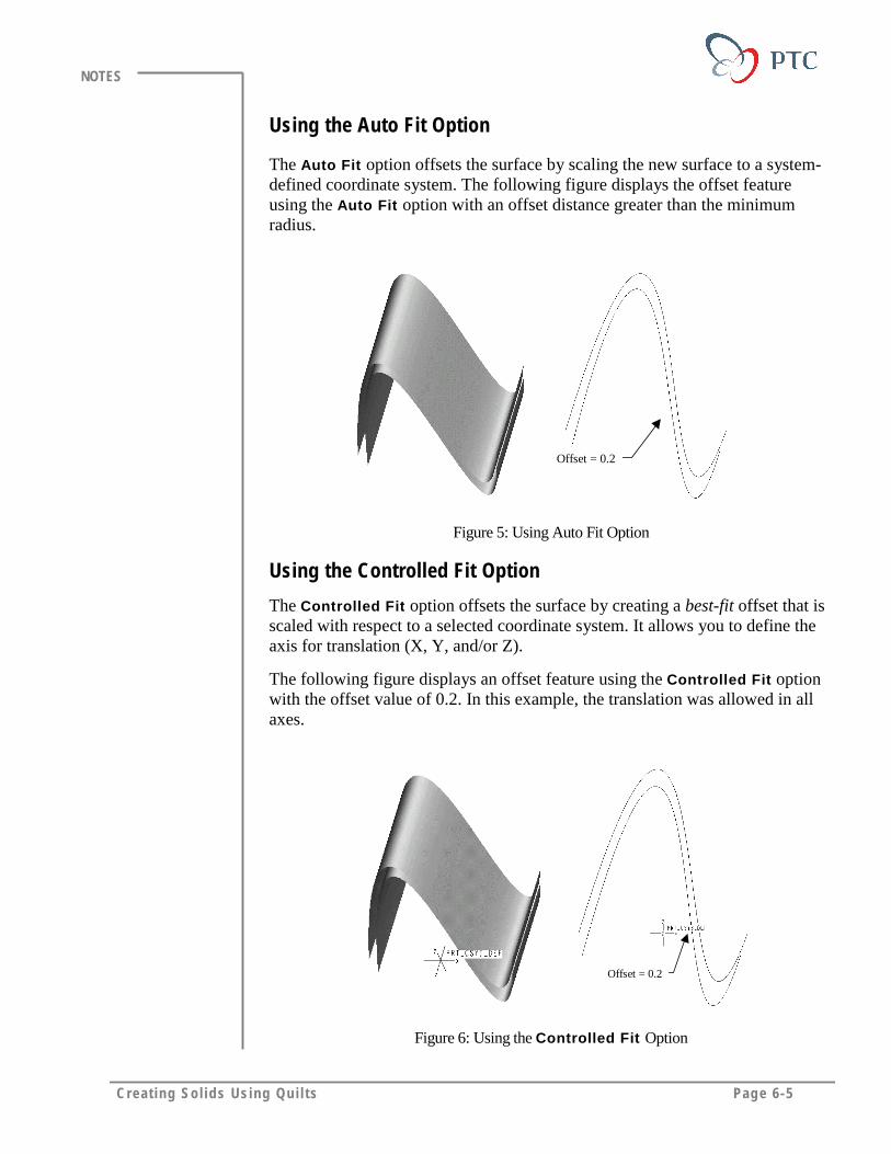
Creat ing Sol ids Using Qu i l ts Page 6-5
NOTES
Using the Auto Fit Option
The Auto Fit option offsets the surface by scaling the new surface to a system-defined coordinate system. The following figure displays the offset featureusing the Auto Fit option with an offset distance greater than the minimumradius.
Offset = 0.2
Figure 5: Using Auto Fit Option
Using the Controlled Fit Option
The Controlled Fit option offsets the surface by creating a best-fit offset that isscaled with respect to a selected coordinate system. It allows you to define theaxis for translation (X, Y, and/or Z).
The following figure displays an offset feature using the Controlled Fit optionwith the offset value of 0.2. In this example, the translation was allowed in allaxes.
Offset = 0.2
Figure 6: Using the Controlled Fit Option
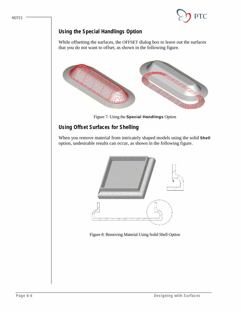
Page 6-6 Des igning w i th Surfaces
NOTES
Using the Special Handlings Option
While offsetting the surfaces, the OFFSET dialog box to leave out the surfacesthat you do not want to offset, as shown in the following figure.
Figure 7: Using the Special Handlings Option
Using Offset Surfaces for Shelling
When you remove material from intricately shaped models using the solid Shelloption, undesirable results can occur, as shown in the following figure.
Figure 8: Removing Material Using Solid Shell Option
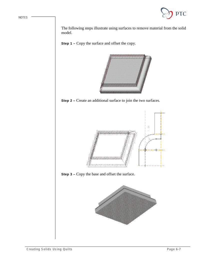
Creat ing Sol ids Using Qu i l ts Page 6-7
NOTES
The following steps illustrate using surfaces to remove material from the solidmodel.
Step 1 – Copy the surface and offset the copy.
Step 2 – Create an additional surface to join the two surfaces.
Step 3 – Copy the base and offset the surface.
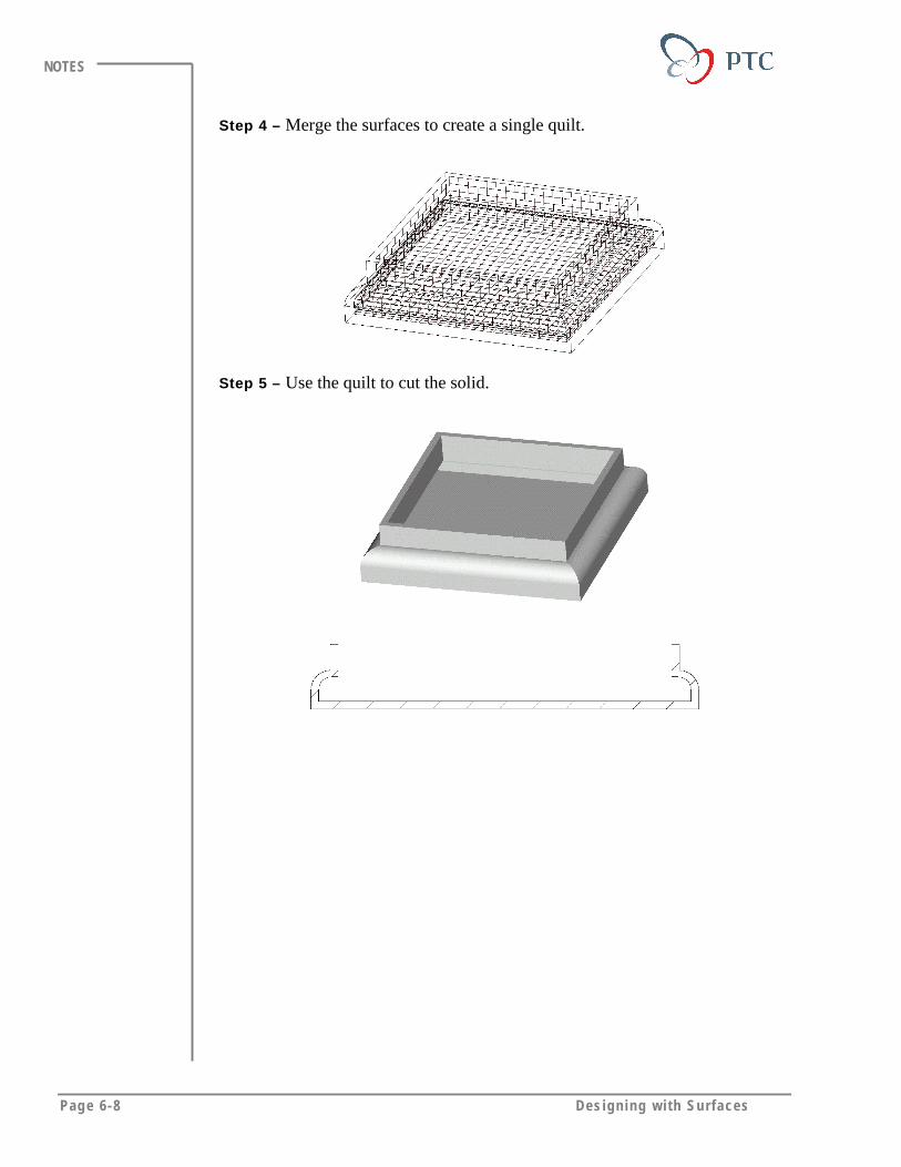
Page 6-8 Des igning w i th Surfaces
NOTES
Step 4 – Merge the surfaces to create a single quilt.
Step 5 – Use the quilt to cut the solid.

Creat ing Sol ids Using Qu i l ts Page 6-9
NOTES
LABORATORY PRACTICALGoal
In this laboratory you create a solid thin feature from a quilt using different
offset options. You also remove material from a solid using a quilt.
Method
In the first exercise, you create a solid part from the quilt of a car hood. Youlearn to use different offset options in order to create thickness that is greaterthan the minimum radius of the quilt.
In the second exercise, you remove material from the cap of projector. You usean offset quilt to remove the material.
ToolsIcon Description
Saved View List
Build Feature
Preview Feature
View Repaint
Done
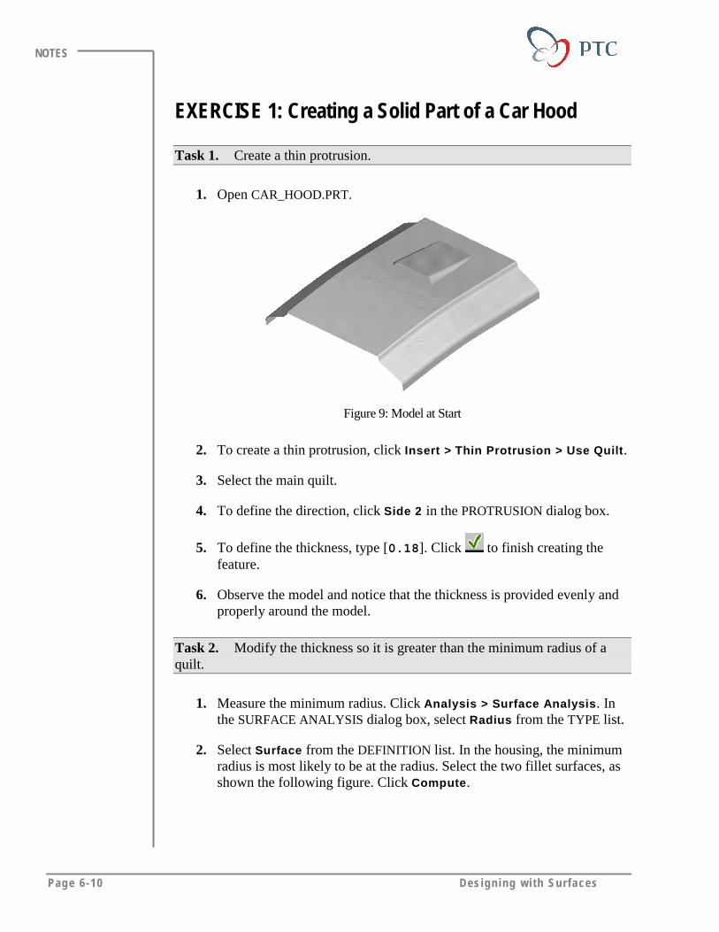
Page 6-10 Des igning w i th Surfaces
NOTES
EXERCISE 1: Creating a Solid Part of a Car Hood
Task 1. Create a thin protrusion.
1. Open CAR_HOOD.PRT.
Figure 9: Model at Start
2. To create a thin protrusion, click Insert > Thin Protrusion > Use Quilt.
3. Select the main quilt.
4. To define the direction, click Side 2 in the PROTRUSION dialog box.
5. To define the thickness, type [0.18]. Click to finish creating thefeature.
6. Observe the model and notice that the thickness is provided evenly andproperly around the model.
Task 2. Modify the thickness so it is greater than the minimum radius of aquilt.
1. Measure the minimum radius. Click Analysis > Surface Analysis. Inthe SURFACE ANALYSIS dialog box, select Radius from the TYPE list.
2. Select Surface from the DEFINITION list. In the housing, the minimumradius is most likely to be at the radius. Select the two fillet surfaces, asshown the following figure. Click Compute.
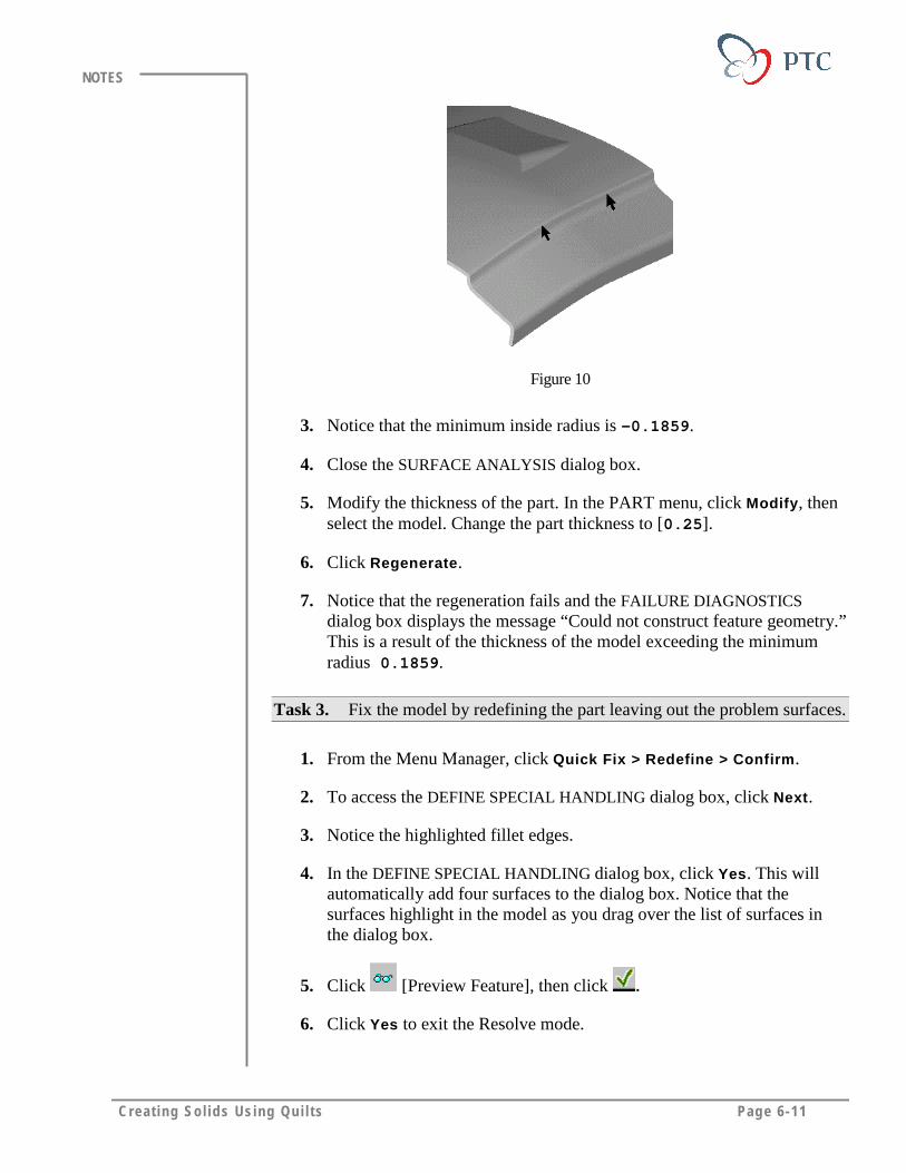
Creat ing Sol ids Using Qu i l ts Page 6-11
NOTES
Figure 10
3. Notice that the minimum inside radius is -0.1859.
4. Close the SURFACE ANALYSIS dialog box.
5. Modify the thickness of the part. In the PART menu, click Modify, thenselect the model. Change the part thickness to [0.25].
6. Click Regenerate.
7. Notice that the regeneration fails and the FAILURE DIAGNOSTICSdialog box displays the message “Could not construct feature geometry.”This is a result of the thickness of the model exceeding the minimumradius 0.1859.
Task 3. Fix the model by redefining the part leaving out the problem surfaces.
1. From the Menu Manager, click Quick Fix > Redefine > Confirm.
2. To access the DEFINE SPECIAL HANDLING dialog box, click Next.
3. Notice the highlighted fillet edges.
4. In the DEFINE SPECIAL HANDLING dialog box, click Yes. This willautomatically add four surfaces to the dialog box. Notice that thesurfaces highlight in the model as you drag over the list of surfaces inthe dialog box.
5. Click [Preview Feature], then click .
6. Click Yes to exit the Resolve mode.

Page 6-12 Des igning w i th Surfaces
NOTES
Task 4. Using pre-defined sections, view the protrusion around the failedfillets.
1. Notice the open round surfaces that are not protruded.
2. To view the pre-defined sections, click X-Section > Show > A, in thePART menu.
3. View the section and notice that the rounds portions did not protrude, asshown in the following figure.
4. When finished click Done/Return.
Figure 11: Section A Detail
Task 5. Make a protrusion that is greater than the minimum radius using theAuto Fit option.
1. To change the offset type, redefine the protrusion. Click Feature >Redefine and select the protrusion.
2. From the OFFSET TYPE area of the dialog box, click Auto Fit.
3. Finish the feature creation. Click OK to accept the warning message,
then click .
4. Study the model in Wireframe display mode. Notice that there are noopen surfaces.
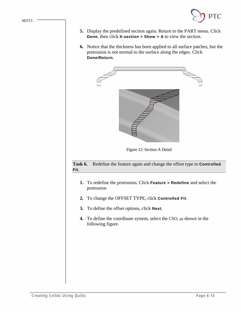
Creat ing Sol ids Using Qu i l ts Page 6-13
NOTES
5. Display the predefined section again. Return to the PART menu. ClickDone, then click X-section > Show > A to view the section.
6. Notice that the thickness has been applied to all surface patches, but theprotrusion is not normal to the surface along the edges. ClickDone/Return.
Figure 12: Section A Detail
Task 6. Redefine the feature again and change the offset type to ControlledFit.
1. To redefine the protrusion. Click Feature > Redefine and select theprotrusion
2. To change the OFFSET TYPE, click Controlled Fit.
3. To define the offset options, click Next.
4. To define the coordinate system, select the CSO, as shown in thefollowing figure.
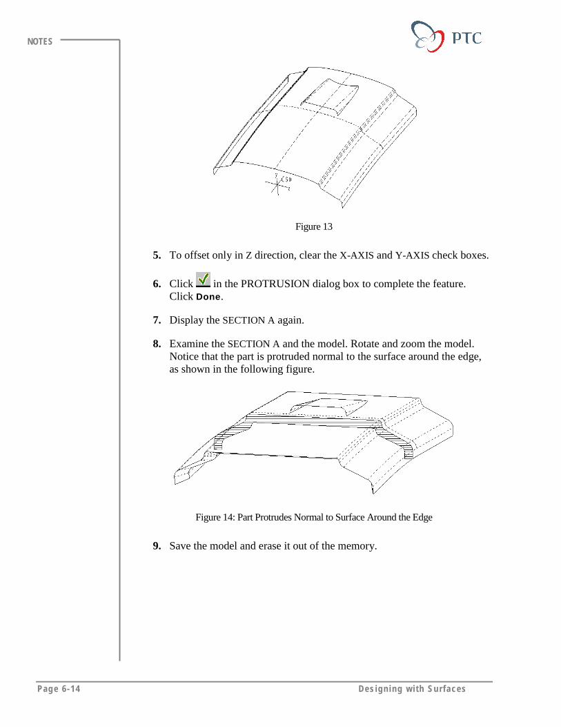
Page 6-14 Des igning w i th Surfaces
NOTES
Figure 13
5. To offset only in Z direction, clear the X-AXIS and Y-AXIS check boxes.
6. Click in the PROTRUSION dialog box to complete the feature.Click Done.
7. Display the SECTION A again.
8. Examine the SECTION A and the model. Rotate and zoom the model.Notice that the part is protruded normal to the surface around the edge,as shown in the following figure.
Figure 14: Part Protrudes Normal to Surface Around the Edge
9. Save the model and erase it out of the memory.

Creat ing Sol ids Using Qu i l ts Page 6-15
NOTES
EXERCISE 2: Using Offset Surfaces for Shelling
Task 1. Remove material from the cap.
1. Open CAP.PRT.
Remove bottom surface
Figure 15: Model at Start
2. To remove material, click Insert > Shell. Select the flat bottom surface,then click Done Sel > Done Refs.
3. Specify the thickness. Type [.33] and click .
4. To finish the feature creation, click OK.
5. Examine the model. Rotate and zoom the model and notice the shelledsolid around the round portion.
Figure 16

Page 6-16 Des igning w i th Surfaces
NOTES
6. To examine the predefined Section A, click X-Section > Show > A.Notice the undesirable section, as shown in the following figure.
Figure 17
7. In the CROSS SEC menu, click Done/Return.
Task 2. Create a quilt, then cut the solid with the quilt.
1. Delete the shell from the previous task. Select the shell feature from theModel Tree. Click Edit > Delete. Click OK in the warning window.
1. Copy the surfaces. Click Insert > Surface > Copy.
2. To copy the surfaces, click Surf & Bnd.
3. To specify the seed surface, select the meshed surface, as shown in thefollowing figure.
Figure 18
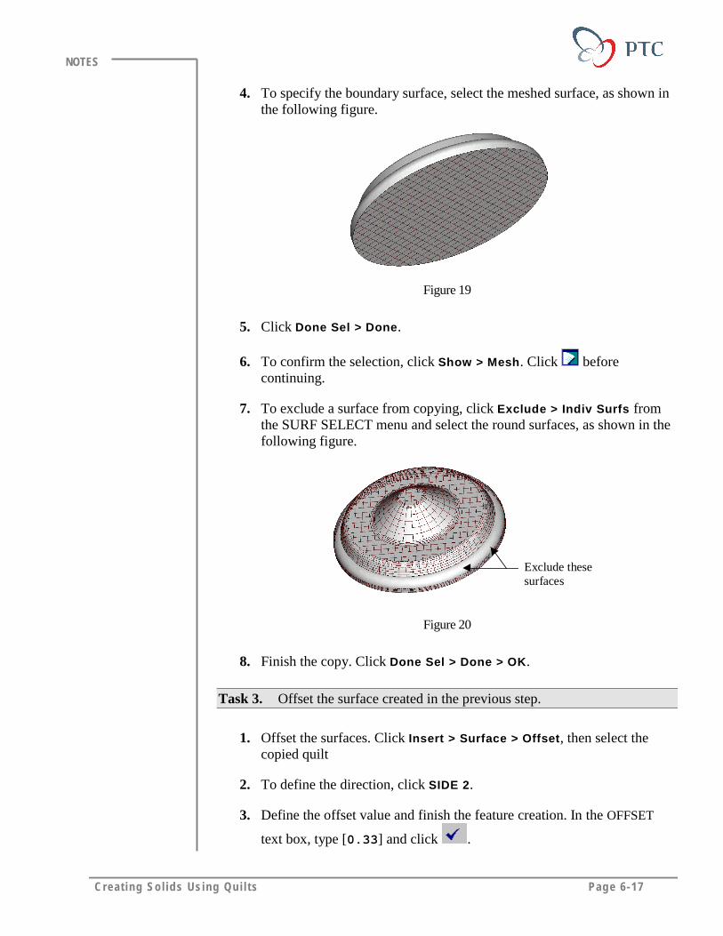
Creat ing Sol ids Using Qu i l ts Page 6-17
NOTES
4. To specify the boundary surface, select the meshed surface, as shown inthe following figure.
Figure 19
5. Click Done Sel > Done.
6. To confirm the selection, click Show > Mesh. Click beforecontinuing.
7. To exclude a surface from copying, click Exclude > Indiv Surfs fromthe SURF SELECT menu and select the round surfaces, as shown in thefollowing figure.
Exclude thesesurfaces
Figure 20
8. Finish the copy. Click Done Sel > Done > OK.
Task 3. Offset the surface created in the previous step.
1. Offset the surfaces. Click Insert > Surface > Offset, then select thecopied quilt
2. To define the direction, click SIDE 2.
3. Define the offset value and finish the feature creation. In the OFFSET
text box, type [0.33] and click .

Page 6-18 Des igning w i th Surfaces
NOTES
Task 4. Create a new surface and merge it with the existing surfaces.
1. Create a new surface. Click Insert > Surface > Revolve. Accept thedefaults and click Done.
2. Setup the sketching plane. Select FRONT and click Okay. To orient,click Top and select the TOP datum plane.
Sketch thesethree entities.
Figure 21
3. Add the existing surfaces as references. Sketch in the two lines, atangent arc and a centerline. Modify the radius of the arc to [0.25].
4. Finish defining the sketch. Click .
5. Specify the rotation. Click 360 > Done. Click OK to create the newrevolved surface.
Task 5. Merge the surfaces together and cut solid using the quilt.
1. Click Insert > Surface Operation > Merge > Join.
7. Select the quilts created in the previous task. (Select the larger surface).
To finish the operation, click .
8. Click Insert > Cut >Use Quilt.
9. Select the merged quilt. Accept the default as SIDE 1. Click .
10. Observe the Section A again.

Creat ing Sol ids Using Qu i l ts Page 6-19
NOTES
Figure 22
11. Save the model and erase it out of the memory.
Page 6-20 Des igning w i th Surfaces
NOTES
MODULE SUMMARYIn this module, you have learned that:
• To create a solid part, you can add thickness to an open quilt or fill a closedquilt.
• By default, you add thickness to an open quilt that is less than its minimumradius.
• You use the Auto Fit and Controlled Fit offset options to provide thicknessthat is greater than the minimum radius.
• You also use quilts to remove material from a solid part in order to providethe desired shape to the inside/outside surfaces and thickness of a shell.
Page 7-1
Module
Boundary SurfacesIn this module, you learn to create different types of boundary
surfaces.
Objectives
After completing this module, you will be able to:
• Create boundary surfaces using part edges and datum curves.
• Define tangency conditions of boundary surfaces.
• Define different types of boundary surfaces.
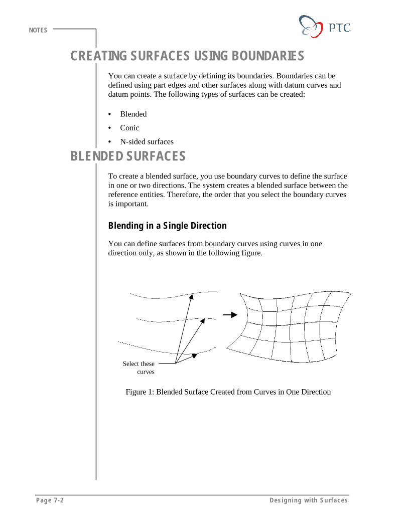
Page 7-2 Des igning w i th Surfaces
NOTES
CREATING SURFACES USING BOUNDARIESYou can create a surface by defining its boundaries. Boundaries can bedefined using part edges and other surfaces along with datum curves anddatum points. The following types of surfaces can be created:
• Blended
• Conic
• N-sided surfaces
BLENDED SURFACESTo create a blended surface, you use boundary curves to define the surfacein one or two directions. The system creates a blended surface between thereference entities. Therefore, the order that you select the boundary curvesis important.
Blending in a Single Direction
You can define surfaces from boundary curves using curves in onedirection only, as shown in the following figure.
Select thesecurves
Figure 1: Blended Surface Created from Curves in One Direction
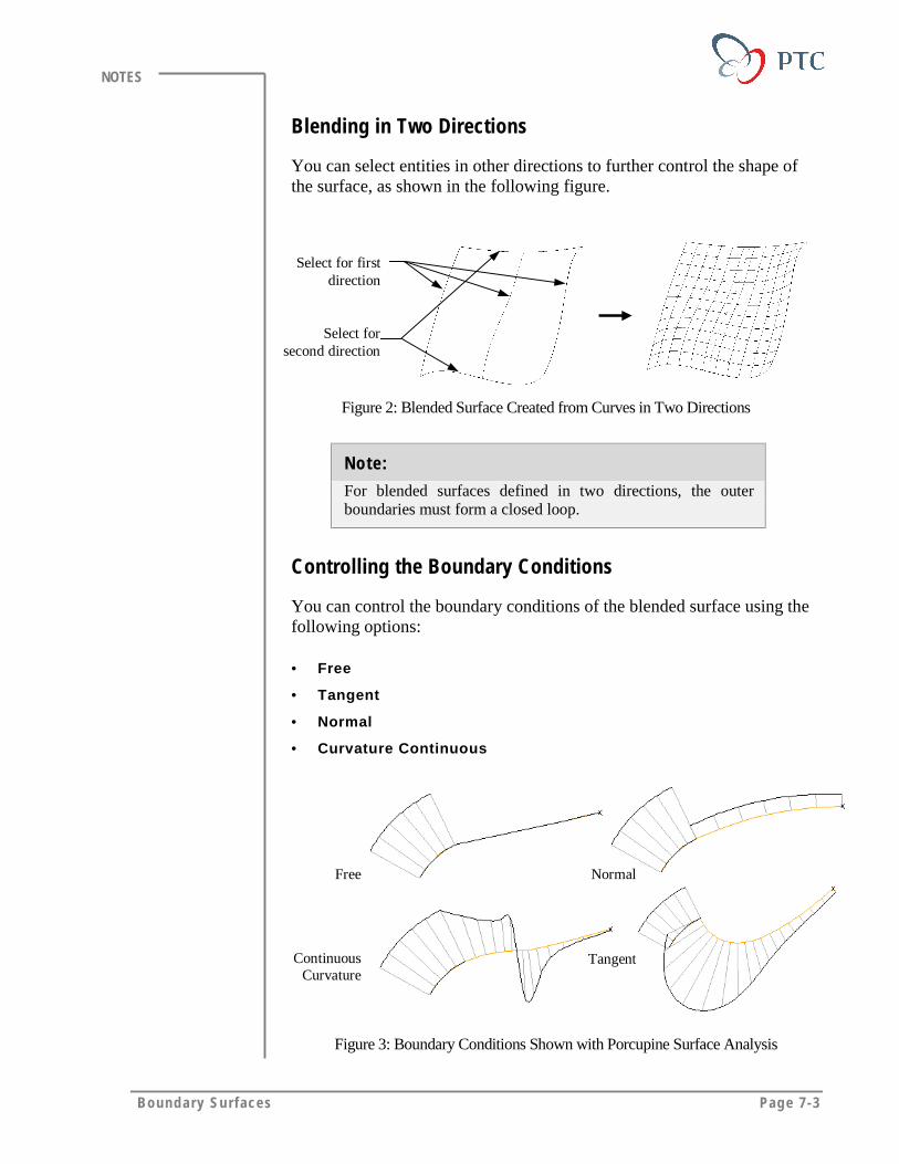
Boundary Surfaces Page 7-3
NOTES
Blending in Two Directions
You can select entities in other directions to further control the shape ofthe surface, as shown in the following figure.
Select for firstdirection
Select forsecond direction
Figure 2: Blended Surface Created from Curves in Two Directions
Note:
For blended surfaces defined in two directions, the outerboundaries must form a closed loop.
Controlling the Boundary Conditions
You can control the boundary conditions of the blended surface using thefollowing options:
• Free
• Tangent
• Normal
• Curvature Continuous
ContinuousCurvature
Tangent
Free Normal
Figure 3: Boundary Conditions Shown with Porcupine Surface Analysis

Page 7-4 Des igning w i th Surfaces
NOTES
Blending the Control Points
When you create blended surfaces from boundary curves, Pro/ENGINEERmay create small patches that cause geometry check errors, undesirabletwisting, and stretching of the surfaces, as shown in the following figure.
Small patches thatcause geometry
check error
Figure 4: Small Patches Created from Surfaces by Boundaries
When you specify corresponding blend control points (either vertices ordatum points) on each of the curves/edges in the same direction, thesystem connects them point –by point and blends the correspondingportions (normalizing from 0 to 100 percent) between the points piece bypiece.
Boundary Influence
You can manipulate the boundaries of adjacent surfaces by defining theboundary influence.
Edges withboundaryinfluence
Figure 5: Boundary Influence
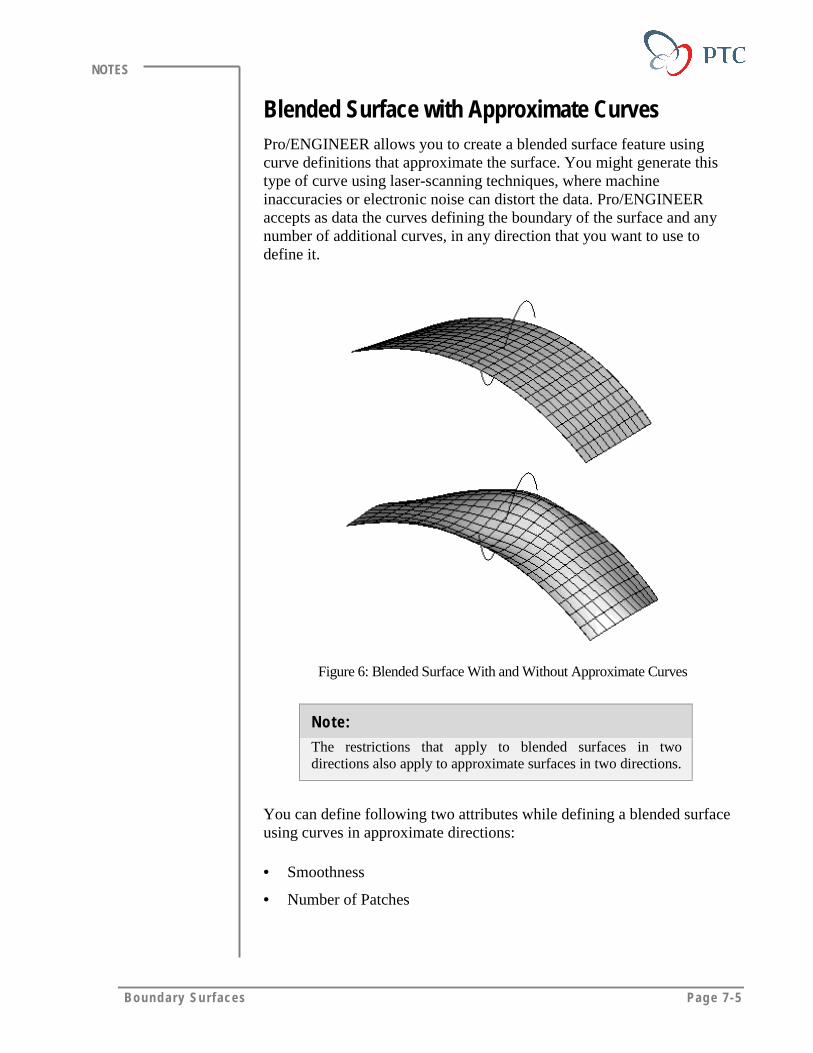
Boundary Surfaces Page 7-5
NOTES
Blended Surface with Approximate CurvesPro/ENGINEER allows you to create a blended surface feature usingcurve definitions that approximate the surface. You might generate thistype of curve using laser-scanning techniques, where machineinaccuracies or electronic noise can distort the data. Pro/ENGINEERaccepts as data the curves defining the boundary of the surface and anynumber of additional curves, in any direction that you want to use todefine it.
Figure 6: Blended Surface With and Without Approximate Curves
Note:
The restrictions that apply to blended surfaces in twodirections also apply to approximate surfaces in two directions.
You can define following two attributes while defining a blended surfaceusing curves in approximate directions:
• Smoothness
• Number of Patches
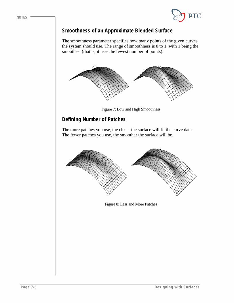
Page 7-6 Des igning w i th Surfaces
NOTES
Smoothness of an Approximate Blended Surface
The smoothness parameter specifies how many points of the given curvesthe system should use. The range of smoothness is 0 to 1, with 1 being thesmoothest (that is, it uses the fewest number of points).
Figure 7: Low and High Smoothness
Defining Number of Patches
The more patches you use, the closer the surface will fit the curve data.The fewer patches you use, the smoother the surface will be.
Figure 8: Less and More Patches
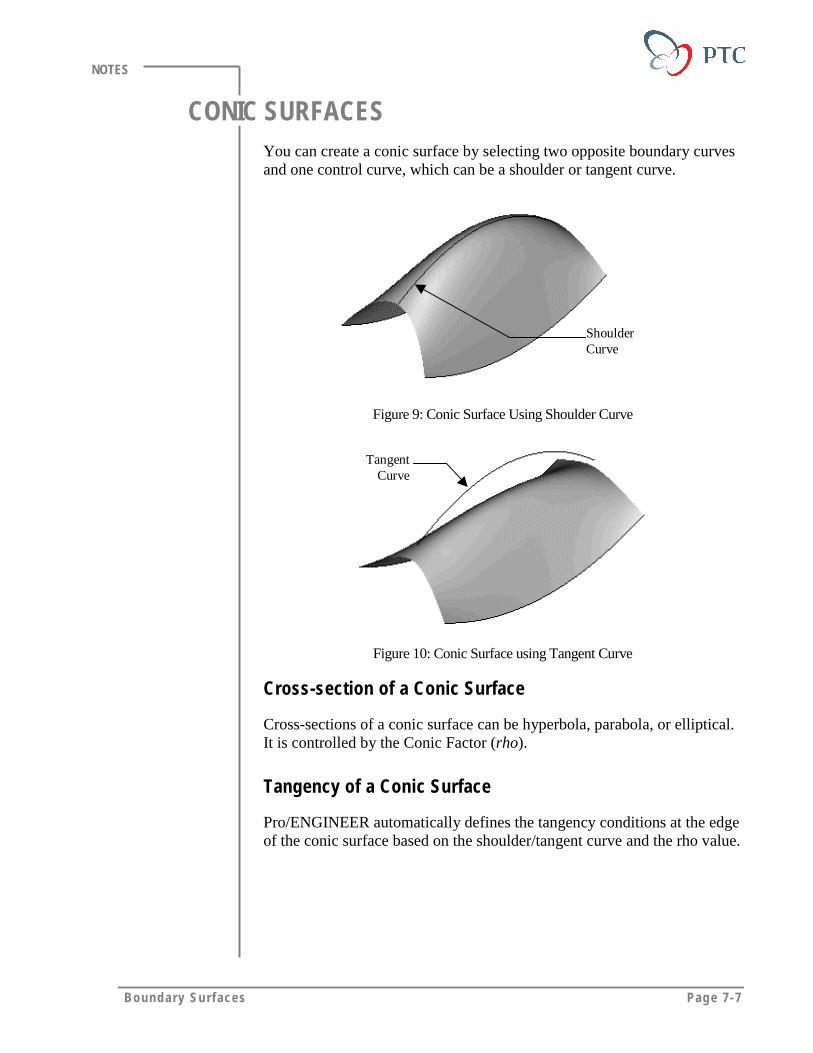
Boundary Surfaces Page 7-7
NOTES
CONIC SURFACESYou can create a conic surface by selecting two opposite boundary curvesand one control curve, which can be a shoulder or tangent curve.
ShoulderCurve
Figure 9: Conic Surface Using Shoulder Curve
TangentCurve
Figure 10: Conic Surface using Tangent Curve
Cross-section of a Conic Surface
Cross-sections of a conic surface can be hyperbola, parabola, or elliptical.It is controlled by the Conic Factor (rho).
Tangency of a Conic Surface
Pro/ENGINEER automatically defines the tangency conditions at the edgeof the conic surface based on the shoulder/tangent curve and the rho value.

Page 7-8 Des igning w i th Surfaces
NOTES
N-SIDED SURFACESYou can create blended surfaces from more than four bounding curves oredges using the N-Sided option, as shown in the following figure.
Figure 11: N-Sided Surfaces
RIBBON SURFACESThe Ribbon surface is a datum feature that is defined using a base curveand the reference curves. You can create a ribbon surface of a specifiedwidth along a base curve. The ribbon surface remains tangential to thereference curves.
Figure 12: Base Curve and Reference Curves
Ribbon surfaces are useful in following situations:
• When the reference curves are intersecting and do not allow you tomake boundary surfaces.
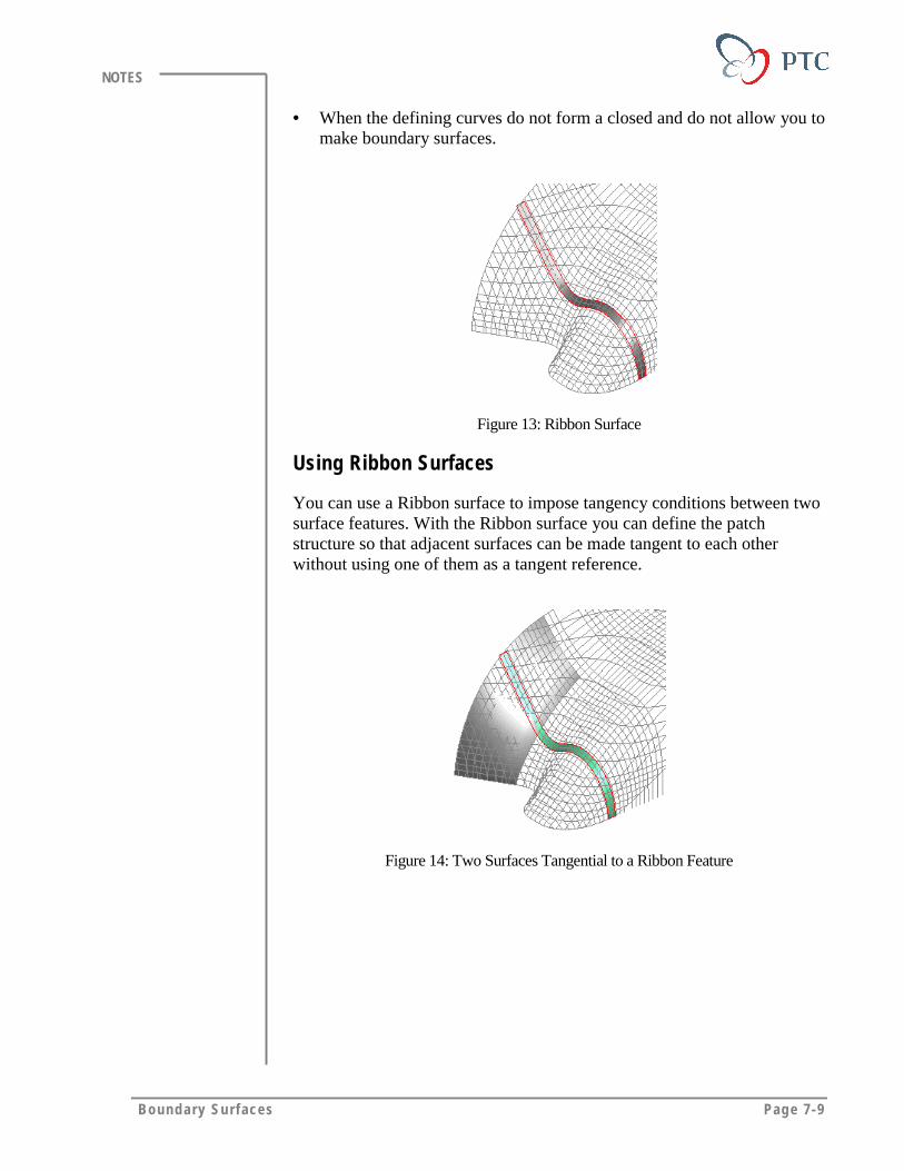
Boundary Surfaces Page 7-9
NOTES
• When the defining curves do not form a closed and do not allow you tomake boundary surfaces.
Figure 13: Ribbon Surface
Using Ribbon Surfaces
You can use a Ribbon surface to impose tangency conditions between twosurface features. With the Ribbon surface you can define the patchstructure so that adjacent surfaces can be made tangent to each otherwithout using one of them as a tangent reference.
Figure 14: Two Surfaces Tangential to a Ribbon Feature

Page 7-10 Des igning w i th Surfaces
NOTES
LABORATORY PRACTICALGoal
In this laboratory, you create blended surfaces using datum curves andedges. You also manipulate the boundary conditions and the blendcontrol points of blended surfaces.
Method
In the first exercise you create blended surfaces to join four cylindricalsurface features together. The blended surfaces are created usingtangential datum curves between the cylindrical surfaces. To join thesurfaces smoothly, you define the boundary conditions to be tangent.
In the second exercise, you create a blended surface then redefine thesurfaces to remove the small patches using the blend control points option.
ToolsIcon Description
Saved View List
Build Feature
View Repaint
Make selected layers Shown
Make selected layers Blanked
Build and repeat the feature
Insert Datum Curve
Insert Datum points
Quality
Show/Hide
Datum Points On/Off
Done
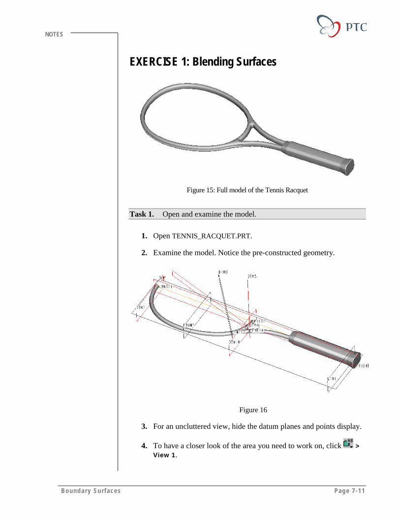
Boundary Surfaces Page 7-11
NOTES
EXERCISE 1: Blending Surfaces
Figure 15: Full model of the Tennis Racquet
Task 1. Open and examine the model.
1. Open TENNIS_RACQUET.PRT.
2. Examine the model. Notice the pre-constructed geometry.
Figure 16
3. For an uncluttered view, hide the datum planes and points display.
4. To have a closer look of the area you need to work on, click >View 1.

Page 7-12 Des igning w i th Surfaces
NOTES
Figure 17
5. Examine the model. Notice the intersection of the two tubes. Youare going to blend the tubes, as shown in the following figure.
Figure 18: Final Blended Surfaces
Task 2. To create a blend between the two tubes, the tubes are trimmedso that they are they are divided in three portions, A, B and C. Hide thetrimmed surfaces and the unwanted geometry.
1. Click View > Layers. In the LAYERS dialog box, select HANDLE,DATUM_PLANES and EXTRA_GEOMETRY. Click .
2. To show the names of the trimmed portions, select TUBES_NAME.
Click > > Close.
Figure 19
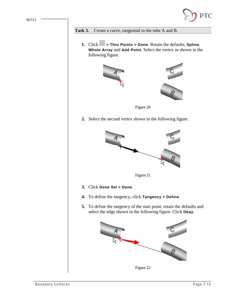
Boundary Surfaces Page 7-13
NOTES
Task 3. Create a curve, tangential to the tube A and B.
1. Click > Thru Points > Done. Retain the defaults, Spline,Whole Array and Add Point. Select the vertex as shown in thefollowing figure.
Figure 20
2. Select the second vertex shown in the following figure.
Figure 21
3. Click Done Sel > Done.
4. To define the tangency, click Tangency > Define.
5. To define the tangency of the start point, retain the defaults andselect the edge shown in the following figure. Click Okay.
Figure 22
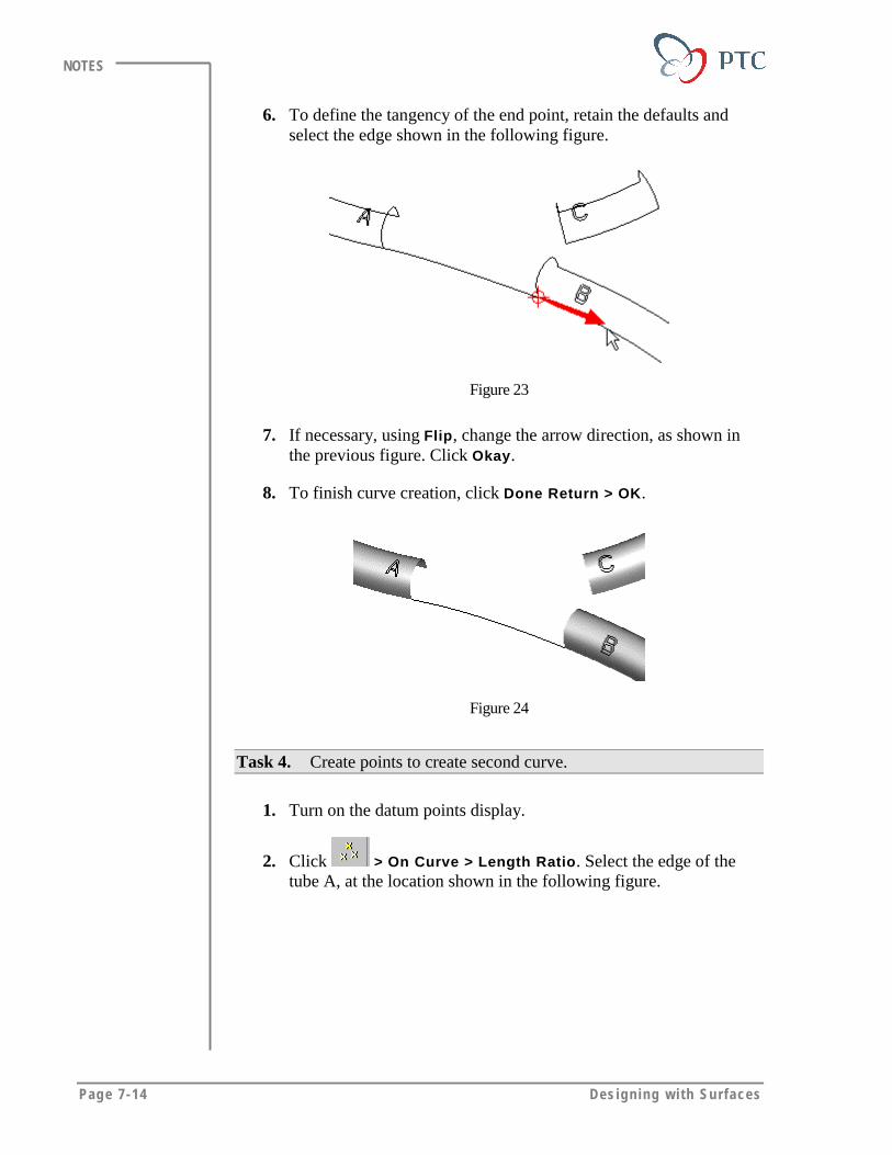
Page 7-14 Des igning w i th Surfaces
NOTES
6. To define the tangency of the end point, retain the defaults andselect the edge shown in the following figure.
Figure 23
7. If necessary, using Flip, change the arrow direction, as shown inthe previous figure. Click Okay.
8. To finish curve creation, click Done Return > OK.
Figure 24
Task 4. Create points to create second curve.
1. Turn on the datum points display.
2. Click > On Curve > Length Ratio. Select the edge of thetube A, at the location shown in the following figure.
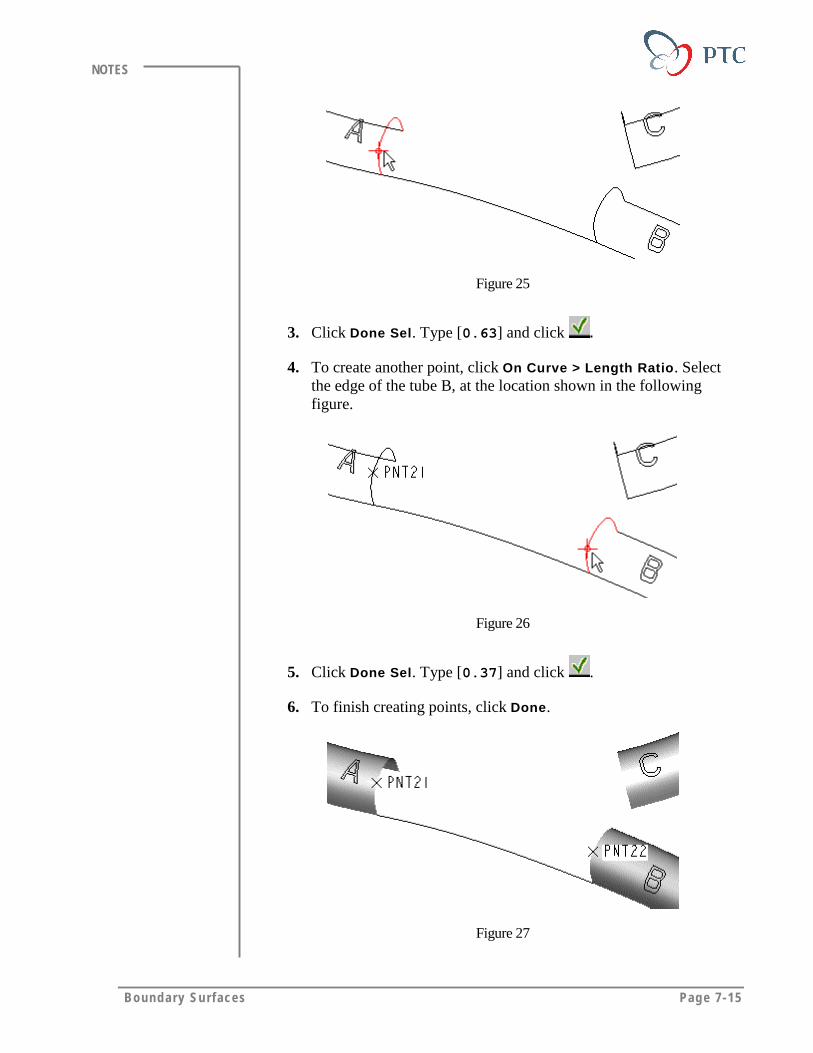
Boundary Surfaces Page 7-15
NOTES
Figure 25
3. Click Done Sel. Type [0.63] and click .
4. To create another point, click On Curve > Length Ratio. Selectthe edge of the tube B, at the location shown in the followingfigure.
Figure 26
5. Click Done Sel. Type [0.37] and click .
6. To finish creating points, click Done.
Figure 27

Page 7-16 Des igning w i th Surfaces
NOTES
Task 5. Cerate a curve tangential to the tube A and B.
1. Using the method outlined in the previous task, create a curvethrough the points, PNT21 and PNT22.
Figure 28
2. To define curve tangency, click Tangency > Define.
3. To define the tangency of the start point, click Srf Nrm Edge.Select the tube A, then select the edge shown in the followingfigure.
Figure 29
4. If necessary, using Flip, change the arrow direction, as shown inthe previous figure. Click Okay.
5. To define the tangency of the end point, click Srf Nrm Edge.Select the tube B, and then select the edge shown in the followingfigure.

Boundary Surfaces Page 7-17
NOTES
Figure 30
6. If necessary, using Flip, change the arrow direction, as shown inthe previous figure. Click Okay.
7. To finish defining the curve, click Done Return > OK.
Figure 31
Task 6. Create a boundary surface, tangential to the tubes A and B.
1. Click Insert > Surface > From Boundaries > Blended Surf >Done.
2. Select first direction curves shown in the following figure, andthen click Done Sel.
Figure 32
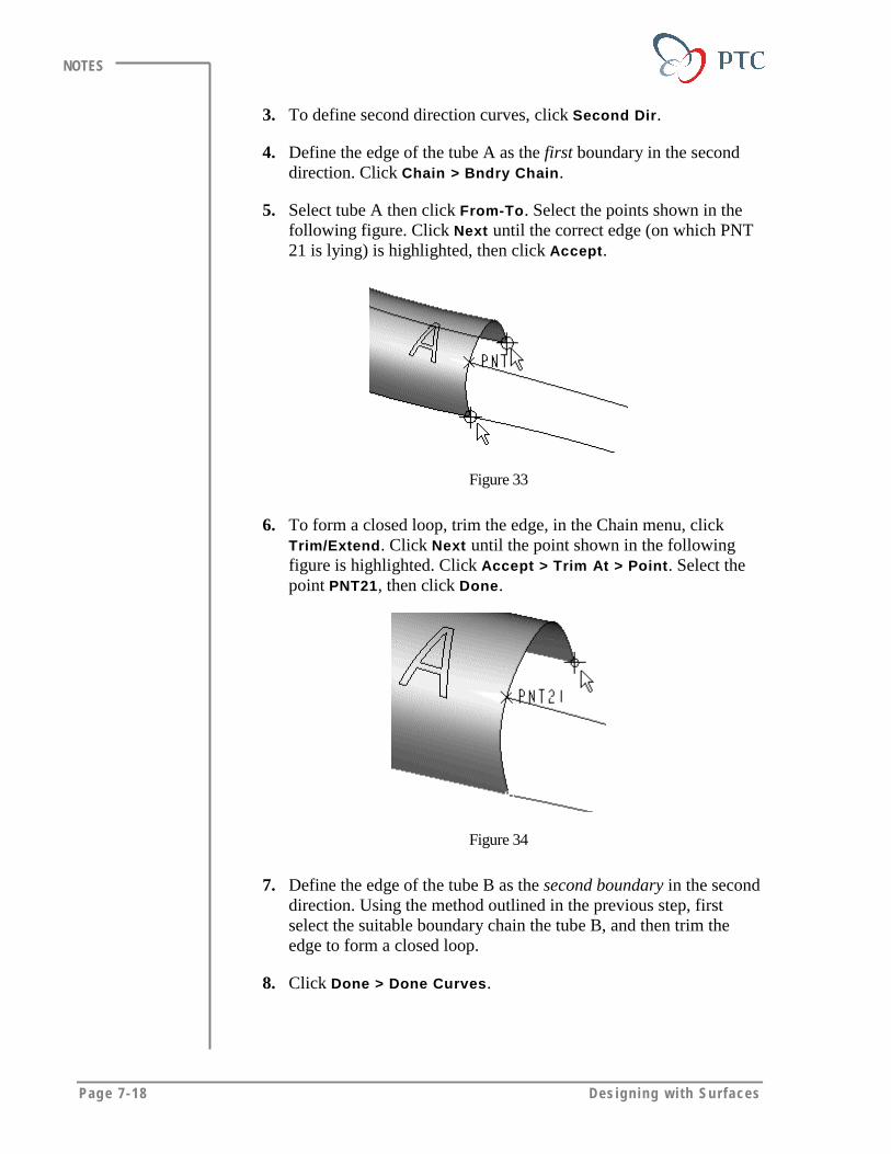
Page 7-18 Des igning w i th Surfaces
NOTES
3. To define second direction curves, click Second Dir.
4. Define the edge of the tube A as the first boundary in the seconddirection. Click Chain > Bndry Chain.
5. Select tube A then click From-To. Select the points shown in thefollowing figure. Click Next until the correct edge (on which PNT21 is lying) is highlighted, then click Accept.
Figure 33
6. To form a closed loop, trim the edge, in the Chain menu, clickTrim/Extend. Click Next until the point shown in the followingfigure is highlighted. Click Accept > Trim At > Point. Select thepoint PNT21, then click Done.
Figure 34
7. Define the edge of the tube B as the second boundary in the seconddirection. Using the method outlined in the previous step, firstselect the suitable boundary chain the tube B, and then trim theedge to form a closed loop.
8. Click Done > Done Curves.
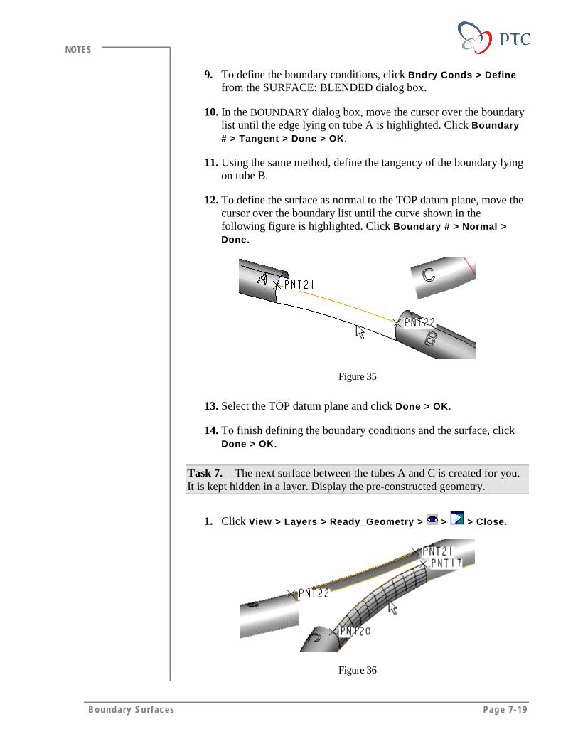
Boundary Surfaces Page 7-19
NOTES
9. To define the boundary conditions, click Bndry Conds > Definefrom the SURFACE: BLENDED dialog box.
10. In the BOUNDARY dialog box, move the cursor over the boundarylist until the edge lying on tube A is highlighted. Click Boundary# > Tangent > Done > OK.
11. Using the same method, define the tangency of the boundary lyingon tube B.
12. To define the surface as normal to the TOP datum plane, move thecursor over the boundary list until the curve shown in thefollowing figure is highlighted. Click Boundary # > Normal >Done.
Figure 35
13. Select the TOP datum plane and click Done > OK.
14. To finish defining the boundary conditions and the surface, clickDone > OK.
Task 7. The next surface between the tubes A and C is created for you.It is kept hidden in a layer. Display the pre-constructed geometry.
1. Click View > Layers > Ready_Geometry > > > Close.
Figure 36

Page 7-20 Des igning w i th Surfaces
NOTES
Task 8. In order to create the next surface, create a curve that istangential to tube B and C.
1. Click > Thru Points > Done. Retain the defaults, Spline,Whole Array, and Add Point. Select PNT 22, then select PNT 20.Click Done.
Figure 37
2. To define the tangency, click Tangency > Define.
3. To make curve tangential to the first boundary surface, click SrfNrm Edge. Select the meshed surface then select the edge shownin the following figure.
Figure 38
4. If necessary, using Flip, change the arrow direction, as shown inthe previous figure. Click Okay.
5. To define the tangency of the end point, click Srf Nrm Edge.Select the meshed surface then select the edge shown in thefollowing figure.
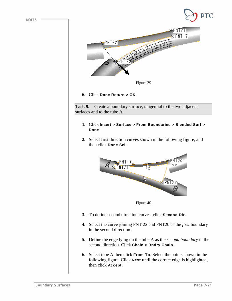
Boundary Surfaces Page 7-21
NOTES
Figure 39
6. Click Done Return > OK.
Task 9. Create a boundary surface, tangential to the two adjacentsurfaces and to the tube A.
1. Click Insert > Surface > From Boundaries > Blended Surf >Done.
2. Select first direction curves shown in the following figure, andthen click Done Sel.
Figure 40
3. To define second direction curves, click Second Dir.
4. Select the curve joining PNT 22 and PNT20 as the first boundaryin the second direction.
5. Define the edge lying on the tube A as the second boundary in thesecond direction. Click Chain > Bndry Chain.
6. Select tube A then click From-To. Select the points shown in thefollowing figure. Click Next until the correct edge is highlighted,then click Accept.

Page 7-22 Des igning w i th Surfaces
NOTES
Figure 41
7. Trim the edge using the method outlined in previous steps. Thetrimmed boundary should lie between points PNT17 and PNT21.
8. Click Done > Done Curves.
9. Using the method outlined in the previous steps, define theboundary conditions so that the surface is tangential to the adjacentboundary surfaces and the tube A.
10. Finish defining the boundary conditions and the surface.
Figure 42
Task 10. In order to make the last surface, create a curve joining thetubes B and C.
1. Click > Thru Points > Done. Retain the defaults, Spline,Whole Array, and Add Point. Select the vertices shown in thefollowing figure.
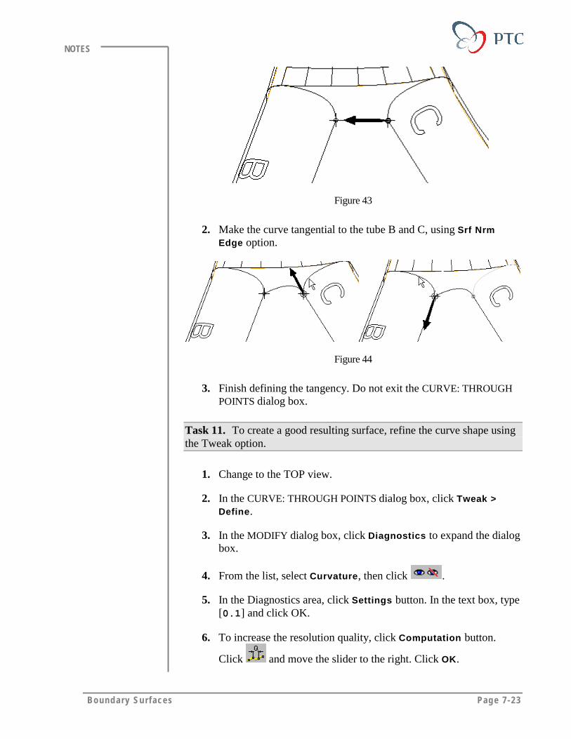
Boundary Surfaces Page 7-23
NOTES
Figure 43
2. Make the curve tangential to the tube B and C, using Srf NrmEdge option.
Figure 44
3. Finish defining the tangency. Do not exit the CURVE: THROUGHPOINTS dialog box.
Task 11. To create a good resulting surface, refine the curve shape usingthe Tweak option.
1. Change to the TOP view.
2. In the CURVE: THROUGH POINTS dialog box, click Tweak >Define.
3. In the MODIFY dialog box, click Diagnostics to expand the dialogbox.
4. From the list, select Curvature, then click .
5. In the Diagnostics area, click Settings button. In the text box, type[0.1] and click OK.
6. To increase the resolution quality, click Computation button.
Click and move the slider to the right. Click OK.
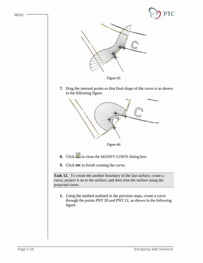
Page 7-24 Des igning w i th Surfaces
NOTES
Figure 45
7. Drag the internal points so that final shape of the curve is as shownin the following figure.
Figure 46
8. Click to close the MODIFY CURVE dialog box.
9. Click OK to finish creating the curve.
Task 12. To create the another boundary of the last surface, create acurve, project it on to the surface, and then trim the surface using theprojected curve.
1. Using the method outlined in the previous steps, create a curvethrough the points PNT 20 and PNT 22, as shown in the followingfigure.
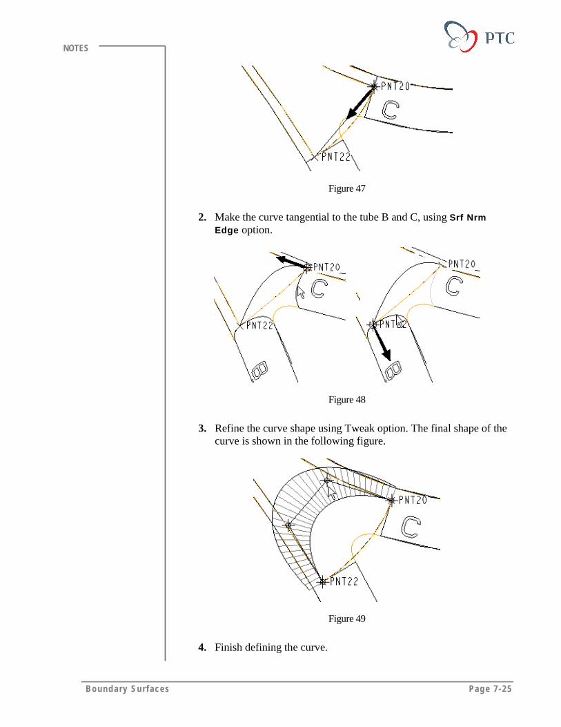
Boundary Surfaces Page 7-25
NOTES
Figure 47
2. Make the curve tangential to the tube B and C, using Srf NrmEdge option.
Figure 48
3. Refine the curve shape using Tweak option. The final shape of thecurve is shown in the following figure.
Figure 49
4. Finish defining the curve.

Page 7-26 Des igning w i th Surfaces
NOTES
Task 13. Project the curve that you have just created, on to the lastsurface and then trim the surface using the projected curve.
1. Click > Projected > Done > Select >Done.
2. Select the curve shown in the following figure.
Figure 50
3. Select the meshed surface shown in the previous figure.
4. Click Along Dir > Done. Select the TOP datum plane. Using Flip,change the arrow direction as shown in the following figure. ClickOkay.
Figure 51
5. To finish defining the curve, click OK.
6. To trim the surface, click Insert > Surface Trim > Use Curves.
7. Select the meshed surface, and then select the projected curveshown in the following figure. Click Done.

Boundary Surfaces Page 7-27
NOTES
Figure 52
8. To define the side to keep, click Side 1 > Done > OK.
Figure 53
Task 14. Create the closing surface.
1. Click Insert > Surface > From Boundaries > Blended Surf >Done.
2. Select first direction curves shown in the following figure, clickDone Sel.
Figure 54
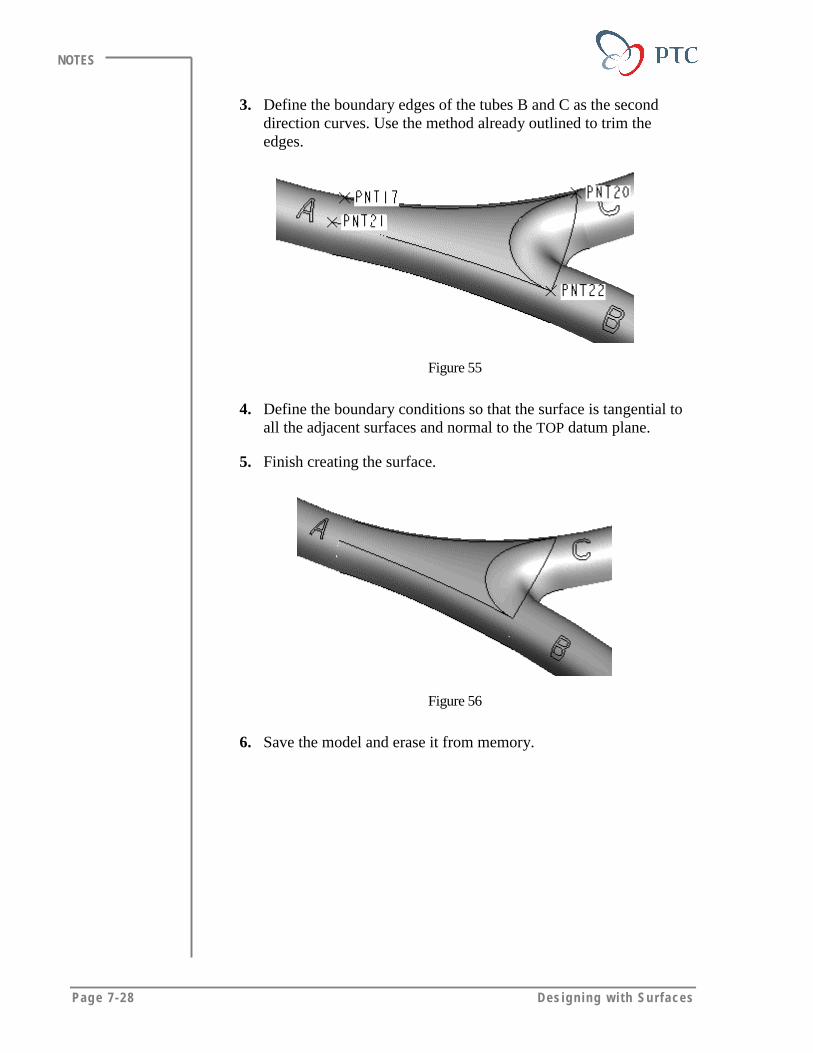
Page 7-28 Des igning w i th Surfaces
NOTES
3. Define the boundary edges of the tubes B and C as the seconddirection curves. Use the method already outlined to trim theedges.
Figure 55
4. Define the boundary conditions so that the surface is tangential toall the adjacent surfaces and normal to the TOP datum plane.
5. Finish creating the surface.
Figure 56
6. Save the model and erase it from memory.
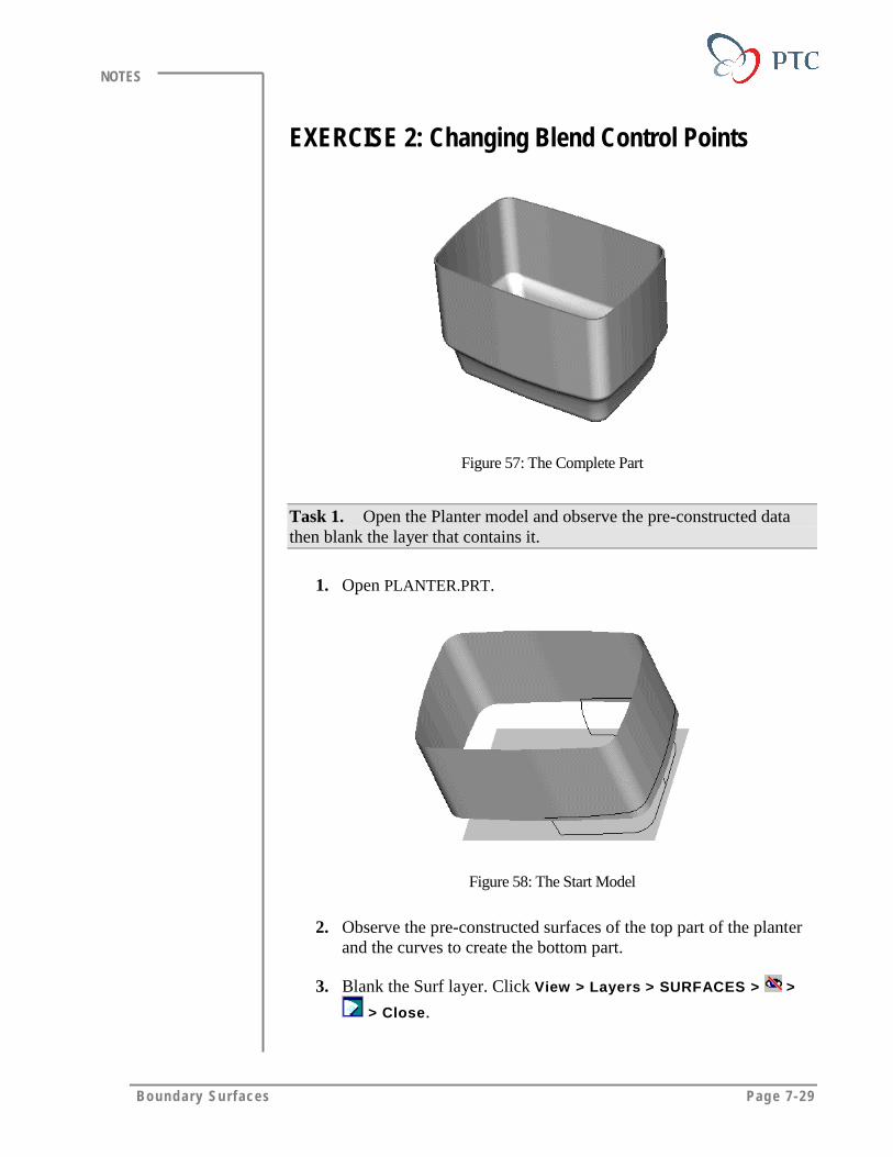
Boundary Surfaces Page 7-29
NOTES
EXERCISE 2: Changing Blend Control Points
Figure 57: The Complete Part
Task 1. Open the Planter model and observe the pre-constructed datathen blank the layer that contains it.
1. Open PLANTER.PRT.
Figure 58: The Start Model
2. Observe the pre-constructed surfaces of the top part of the planterand the curves to create the bottom part.
3. Blank the Surf layer. Click View > Layers > SURFACES > >
> Close.

Page 7-30 Des igning w i th Surfaces
NOTES
4. To change the view click > View1.
Task 2. Create a surface-by-boundaries using datum curves.
1. Create a blended surface. Click Insert > Surface > FromBoundaries > Blended Surf >Done.
Figure 59: First Direction Curves
2. To define the curves in the first direction, retain the defaults FirstDir, Add Item, and Curve. Select the curves shown in thepreceding figure. Click Done Sel.
3. To define the curves in the second direction, click Second Dir.Retain the defaults Add Item and Curve and select the two largercurves. Click Done Sel.
4. Finish defining the curves and preview the surface. Click DoneCurves then click Preview.
Figure 60: Previewing Curves
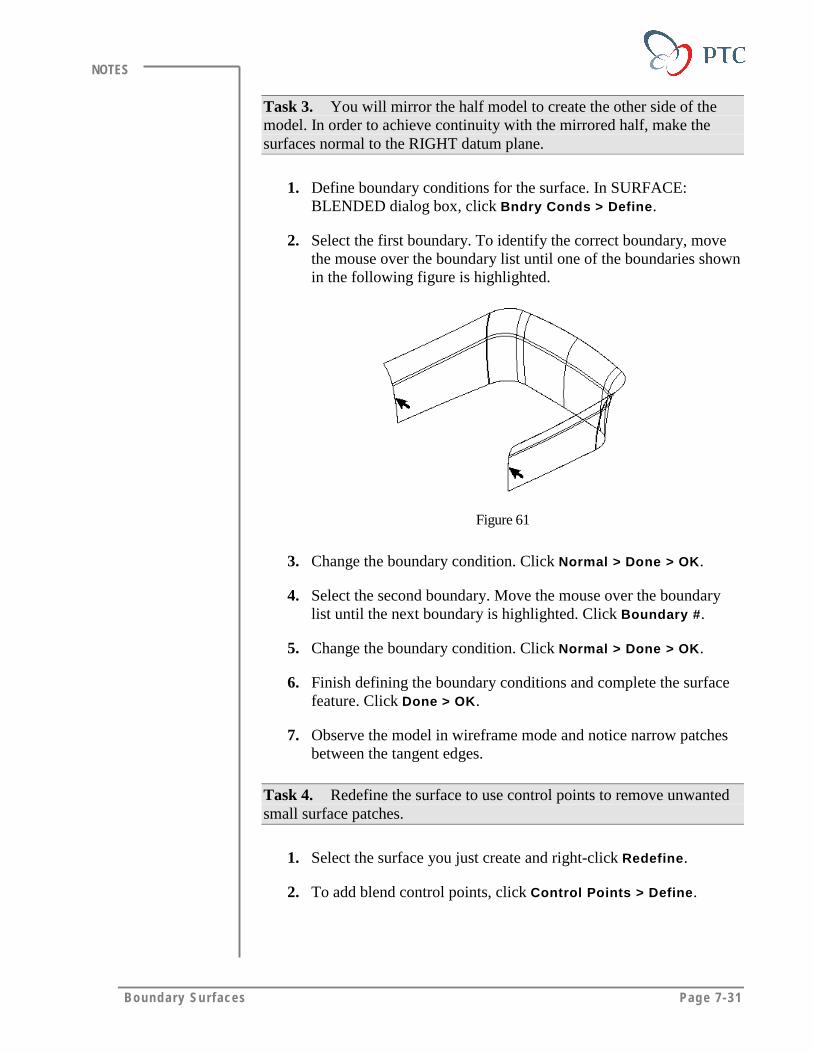
Boundary Surfaces Page 7-31
NOTES
Task 3. You will mirror the half model to create the other side of themodel. In order to achieve continuity with the mirrored half, make thesurfaces normal to the RIGHT datum plane.
1. Define boundary conditions for the surface. In SURFACE:BLENDED dialog box, click Bndry Conds > Define.
2. Select the first boundary. To identify the correct boundary, movethe mouse over the boundary list until one of the boundaries shownin the following figure is highlighted.
Figure 61
3. Change the boundary condition. Click Normal > Done > OK.
4. Select the second boundary. Move the mouse over the boundarylist until the next boundary is highlighted. Click Boundary #.
5. Change the boundary condition. Click Normal > Done > OK.
6. Finish defining the boundary conditions and complete the surfacefeature. Click Done > OK.
7. Observe the model in wireframe mode and notice narrow patchesbetween the tangent edges.
Task 4. Redefine the surface to use control points to remove unwantedsmall surface patches.
1. Select the surface you just create and right-click Redefine.
2. To add blend control points, click Control Points > Define.
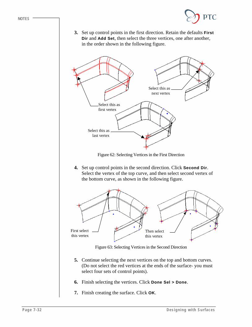
Page 7-32 Des igning w i th Surfaces
NOTES
3. Set up control points in the first direction. Retain the defaults FirstDir and Add Set, then select the three vertices, one after another,in the order shown in the following figure.
Select this asfirst vertex
Select this asnext vertex
Select this aslast vertex
Figure 62: Selecting Vertices in the First Direction
4. Set up control points in the second direction. Click Second Dir.Select the vertex of the top curve, and then select second vertex ofthe bottom curve, as shown in the following figure.
First selectthis vertex
Then selectthis vertex
Figure 63: Selecting Vertices in the Second Direction
5. Continue selecting the next vertices on the top and bottom curves.(Do not select the red vertices at the ends of the surface- you mustselect four sets of control points).
6. Finish selecting the vertices. Click Done Sel > Done.
7. Finish creating the surface. Click OK.
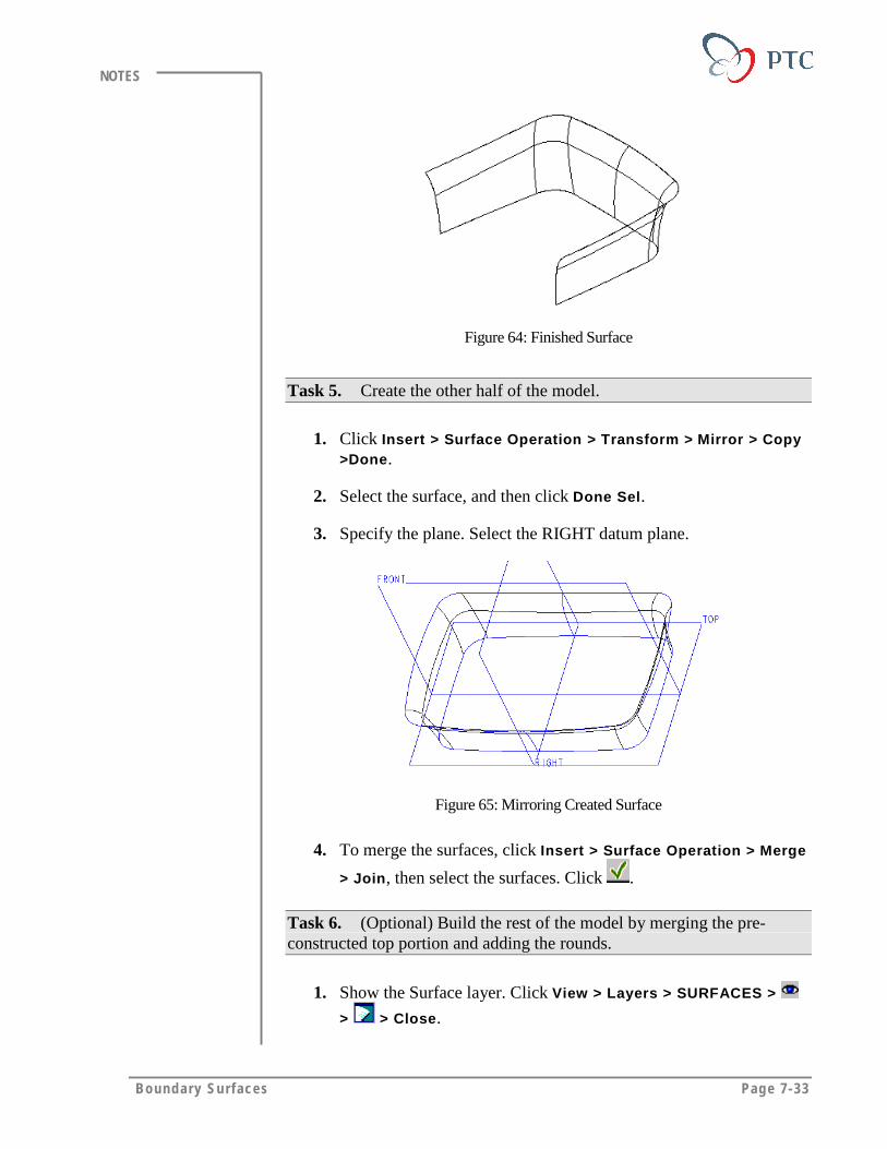
Boundary Surfaces Page 7-33
NOTES
Figure 64: Finished Surface
Task 5. Create the other half of the model.
1. Click Insert > Surface Operation > Transform > Mirror > Copy>Done.
2. Select the surface, and then click Done Sel.
3. Specify the plane. Select the RIGHT datum plane.
Figure 65: Mirroring Created Surface
4. To merge the surfaces, click Insert > Surface Operation > Merge
> Join, then select the surfaces. Click .
Task 6. (Optional) Build the rest of the model by merging the pre-constructed top portion and adding the rounds.
1. Show the Surface layer. Click View > Layers > SURFACES >
> > Close.
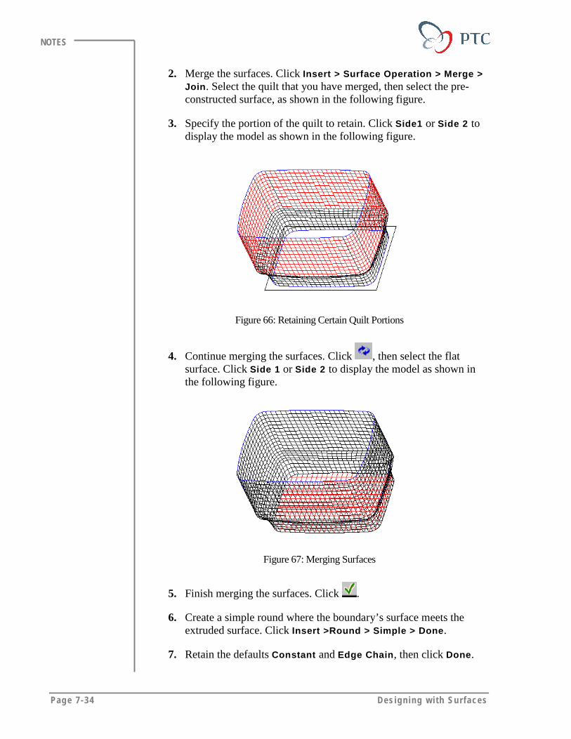
Page 7-34 Des igning w i th Surfaces
NOTES
2. Merge the surfaces. Click Insert > Surface Operation > Merge >Join. Select the quilt that you have merged, then select the pre-constructed surface, as shown in the following figure.
3. Specify the portion of the quilt to retain. Click Side1 or Side 2 todisplay the model as shown in the following figure.
Figure 66: Retaining Certain Quilt Portions
4. Continue merging the surfaces. Click , then select the flatsurface. Click Side 1 or Side 2 to display the model as shown inthe following figure.
Figure 67: Merging Surfaces
5. Finish merging the surfaces. Click .
6. Create a simple round where the boundary’s surface meets theextruded surface. Click Insert >Round > Simple > Done.
7. Retain the defaults Constant and Edge Chain, then click Done.
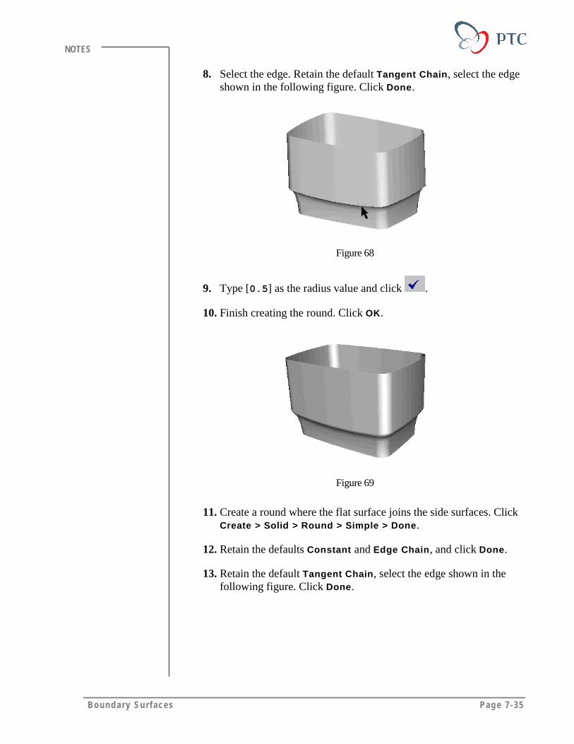
Boundary Surfaces Page 7-35
NOTES
8. Select the edge. Retain the default Tangent Chain, select the edgeshown in the following figure. Click Done.
Figure 68
9. Type [0.5] as the radius value and click .
10. Finish creating the round. Click OK.
Figure 69
11. Create a round where the flat surface joins the side surfaces. ClickCreate > Solid > Round > Simple > Done.
12. Retain the defaults Constant and Edge Chain, and click Done.
13. Retain the default Tangent Chain, select the edge shown in thefollowing figure. Click Done.
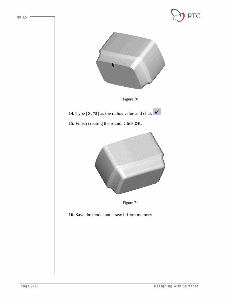
Page 7-36 Des igning w i th Surfaces
NOTES
Figure 70
14. Type [0.75] as the radius value and click .
15. Finish creating the round. Click OK.
Figure 71
16. Save the model and erase it from memory.
Boundary Surfaces Page 7-37
NOTES
MODULE SUMMARYIn this module, you have learned that:
• You can create Blended, Conic, and N-Sided surfaces usingboundaries.
• You can make boundary surfaces tangential to the adjacent surfaces byredefining the boundary conditions.
• You can make smooth, large surface patches by manipulating theblend control points.


Page 8-1
Module
Variable Section SweepIn this module, you learn to create variable section sweeps to capture
the design intent of complex shapes.
Objectives
After completing this module you will be able to:
• Define different types of trajectories in order to control the shapeof a variable section sweep.
• Manipulate the shape of a variable section sweep using variousoptions to orient the cross section.
• Define the tangent conditions to create a continuous variablesection sweep.
• Define limitations on a variable section sweep.
Page 8-2 Des igning w i th Surfaces
NOTES
THE VARIABLE SECTION SWEEPVariable section sweeps capture the design intent of complex shapes. Tocreate a variable section sweep feature, you sweep a single sketchedsection along one or more trajectories. The size and shape of the sectionvaries as the section moves along the sweep trajectories. You select thetrajectories from datum curves or sketch them during feature creation.
Defining Trajectories• Origin Trajectory – The one spine trajectory necessary in every
variable section sweep.
• X-Trajectory – Defines the section’s horizontal vector. In theSketcher, the origin of the section (indicated by the two centerlines) isalways located on the Origin Trajectory with the X-trajectory alwayslocated in the positive x direction.
• Other Trajectories – Defines other trajectories to control the shape ofthe surface feature.
Tips & Techniques:
You build flexibility into your model by selecting datumcurves to create the sweep trajectories instead of sketchingthem.
Specifying Section OrientationThe variable section sweep feature enables you to control how the systemsweeps the cross section to the origin trajectory. You define the feature byspecifying the orientation of the cross section with the following options:
Normal to Origin Trajectory
You sweep the section along the origin trajectory with a constant normaltrajectory. The origin trajectory curve defines a perpendicular for thesection as it sweeps along the trajectory.
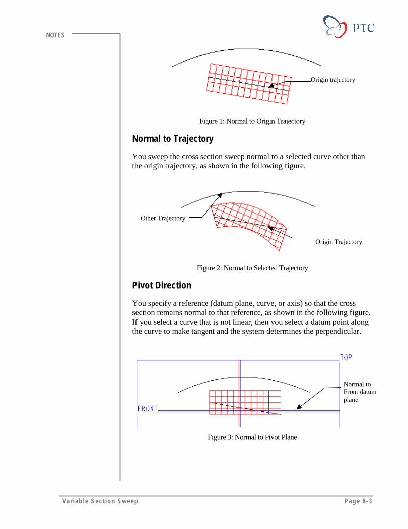
Var iab le Sect ion Sweep Page 8-3
NOTES
Origin trajectory
Figure 1: Normal to Origin Trajectory
Normal to Trajectory
You sweep the cross section sweep normal to a selected curve other thanthe origin trajectory, as shown in the following figure.
Origin Trajectory
Other Trajectory
Figure 2: Normal to Selected Trajectory
Pivot Direction
You specify a reference (datum plane, curve, or axis) so that the crosssection remains normal to that reference, as shown in the following figure.If you select a curve that is not linear, then you select a datum point alongthe curve to make tangent and the system determines the perpendicular.
Normal toFront datumplane
Figure 3: Normal to Pivot Plane

Page 8-4 Des igning w i th Surfaces
NOTES
Creating a Normal to origin Trajectory Variable SectionSweep
When creating a normal to origin trajectory variable section sweep, youdefine at least one additional trajectory—the X-trajectory. The system usesthis trajectory to orient the section during the sweep. The section plane isalways normal to the origin trajectory at their intersection, as shown in thefollowing figure.
Resulting feature twists dueto change in horizontal
determined by x-trajectory
Origin trajectory
x-trajectory X-trajectory setsup horizontal forSketcher
Figure 4: Result of X-Vector
Using Additional Trajectories to Define the Shape
Once you have defined the origin trajectory and x-trajectory (whenneeded), you select or sketch additional trajectories to define the shape ofthe swept section, as shown in the following figure. Pro/ENGINEERautomatically add a Sketcher point at the intersection of any additionaltrajectory and the sketching plane of the section. As the system sweeps thesection plane along the trajectories, its intersection with the curves(trajectories) represents known points for section dimension andalignment. When you dimension or align section vertices to the x-trajectory and additional trajectories, these curves represent the trajectoryof the section vertex.
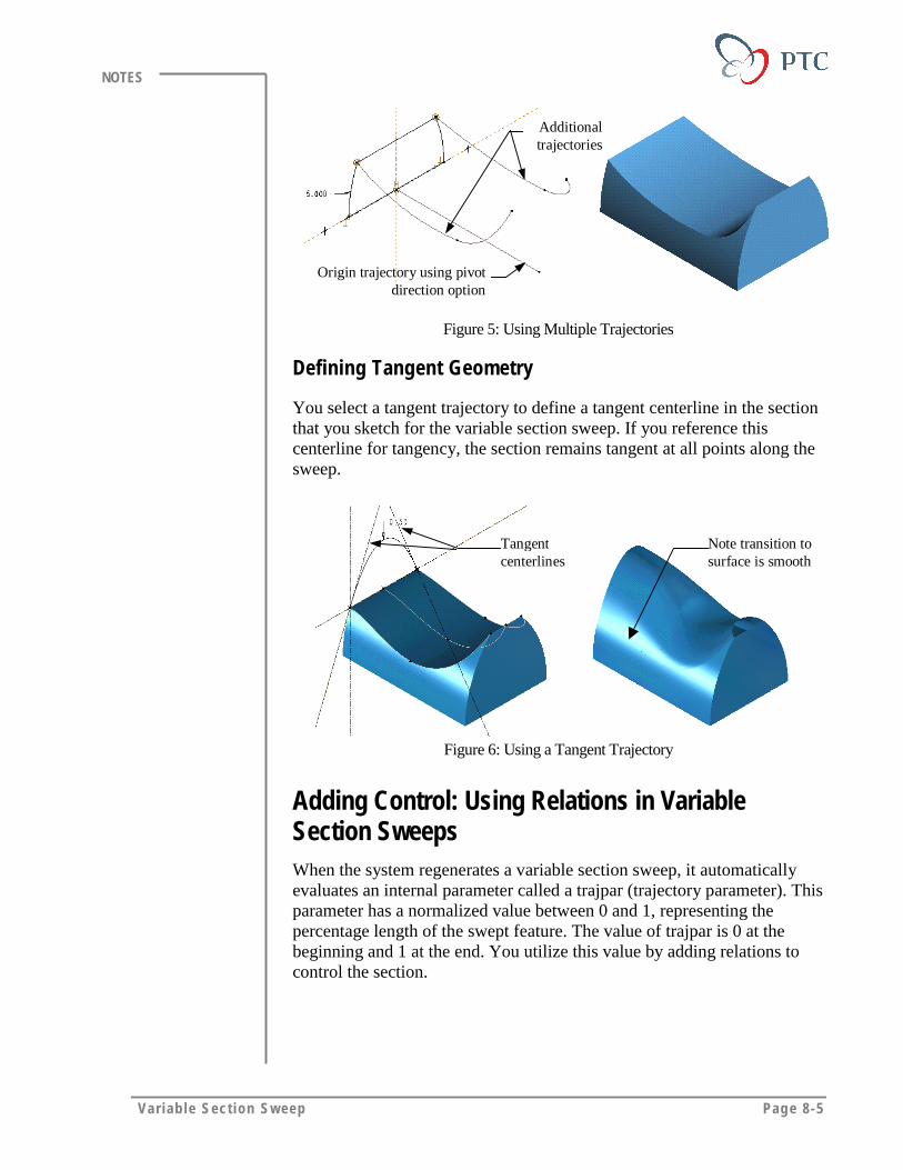
Var iab le Sect ion Sweep Page 8-5
NOTES
Origin trajectory using pivotdirection option
Additionaltrajectories
Figure 5: Using Multiple Trajectories
Defining Tangent Geometry
You select a tangent trajectory to define a tangent centerline in the sectionthat you sketch for the variable section sweep. If you reference thiscenterline for tangency, the section remains tangent at all points along thesweep.
Tangentcenterlines
Note transition tosurface is smooth
Figure 6: Using a Tangent Trajectory
Adding Control: Using Relations in VariableSection SweepsWhen the system regenerates a variable section sweep, it automaticallyevaluates an internal parameter called a trajpar (trajectory parameter). Thisparameter has a normalized value between 0 and 1, representing thepercentage length of the swept feature. The value of trajpar is 0 at thebeginning and 1 at the end. You utilize this value by adding relations tocontrol the section.
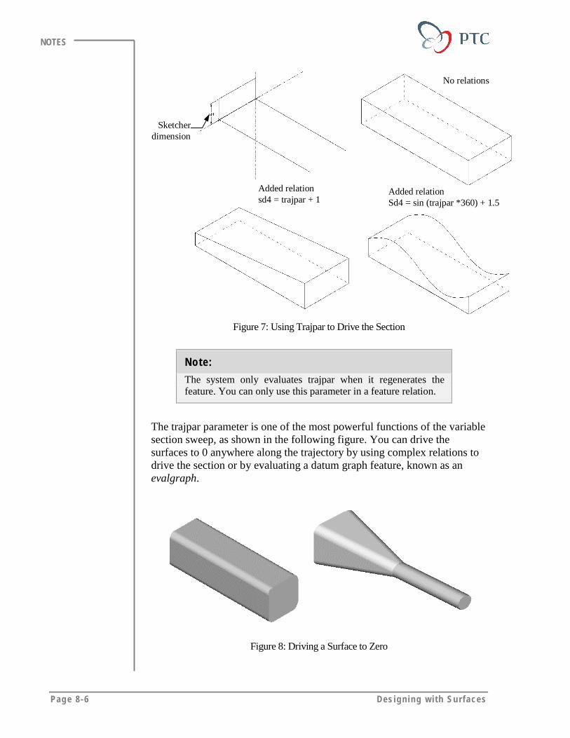
Page 8-6 Des igning w i th Surfaces
NOTES
Sketcherdimension
No relations
Added relationsd4 = trajpar + 1
Added relationSd4 = sin (trajpar *360) + 1.5
Figure 7: Using Trajpar to Drive the Section
Note:
The system only evaluates trajpar when it regenerates thefeature. You can only use this parameter in a feature relation.
The trajpar parameter is one of the most powerful functions of the variablesection sweep, as shown in the following figure. You can drive thesurfaces to 0 anywhere along the trajectory by using complex relations todrive the section or by evaluating a datum graph feature, known as anevalgraph.
Figure 8: Driving a Surface to Zero

Var iab le Sect ion Sweep Page 8-7
NOTES
Restrictions on Variable Section SweepsA variable section sweep cannot be the first feature in a model, so you usethe default datum planes first. When you create a variable section sweep:
• The origin trajectory curve must consist of only tangent entities.
• The x-trajectory cannot cross the origin trajectory. However, eitherend point can intersect the origin trajectory.
• All additional trajectories intersect the sweep’s sketching plane, but donot have to be the same length as the origin trajectory. The systemmakes the sweep feature as long as the shortest trajectory (origintrajectory, x-vector, or optional trajectory).
• The sweep feature’s sketching plane can intersect any trajectory onlyonce at any given location along the sweep.
• If the sweep feature’s sketching plane cannot intersect all trajectoriesat the sweep’s start point, you can use a datum point (on the origintrajectory) to define the start point.
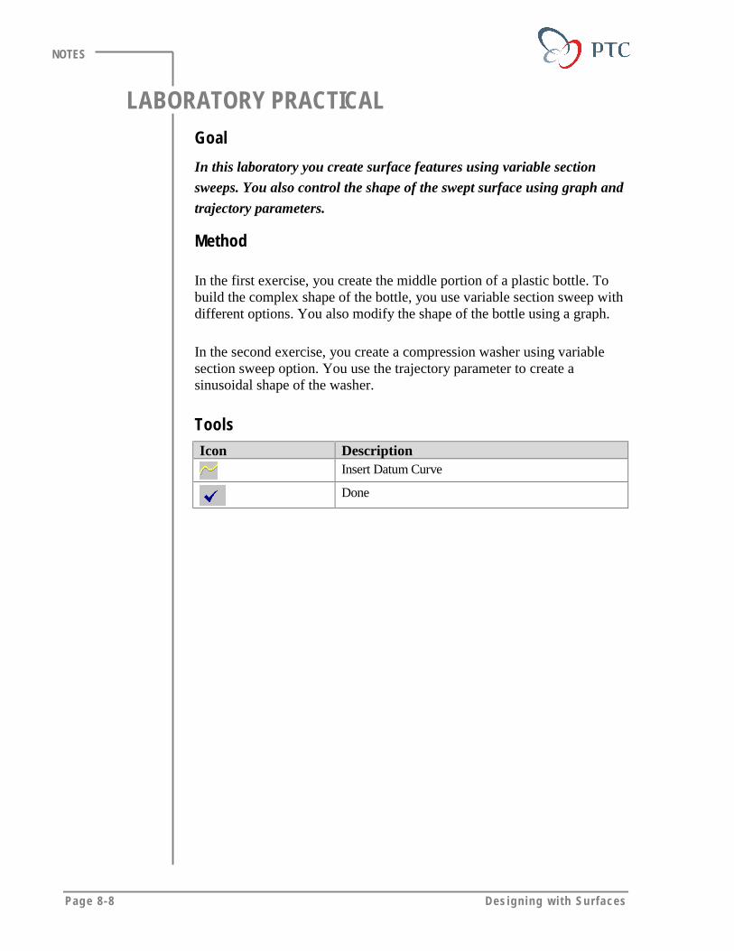
Page 8-8 Des igning w i th Surfaces
NOTES
LABORATORY PRACTICALGoal
In this laboratory you create surface features using variable section
sweeps. You also control the shape of the swept surface using graph and
trajectory parameters.
Method
In the first exercise, you create the middle portion of a plastic bottle. Tobuild the complex shape of the bottle, you use variable section sweep withdifferent options. You also modify the shape of the bottle using a graph.
In the second exercise, you create a compression washer using variablesection sweep option. You use the trajectory parameter to create asinusoidal shape of the washer.
ToolsIcon Description
Insert Datum Curve
Done
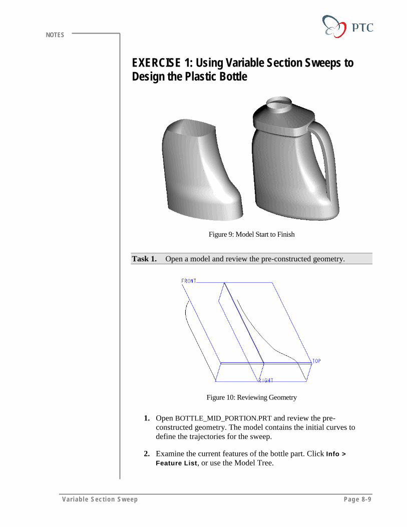
Var iab le Sect ion Sweep Page 8-9
NOTES
EXERCISE 1: Using Variable Section Sweeps toDesign the Plastic Bottle
Figure 9: Model Start to Finish
Task 1. Open a model and review the pre-constructed geometry.
Figure 10: Reviewing Geometry
1. Open BOTTLE_MID_PORTION.PRT and review the pre-constructed geometry. The model contains the initial curves todefine the trajectories for the sweep.
2. Examine the current features of the bottle part. Click Info >Feature List, or use the Model Tree.

Page 8-10 Des igning w i th Surfaces
NOTES
3. Note the datum graph feature named CONIC. You use this later tocontrol a variable section sweep.
4. When you have finished reviewing the model, close all informationwindows.
Task 2. Construct the front side of the bottle using a variable sectionsweep.
1. Turn off the datum plane display to see the curves properly.
2. Create a variable section sweep surface. Click Insert > Surface >Variable Section Sweep > NrmToOriginTraj > Done.
3. To specify the origin trajectory, click Select Traj. Retain thedefaults One By One and Select. Select the straight datum curve,then click Done Sel.
4. Confirm that the start point of the sweep is at the bottom, as shownin the following figure. If necessary, change the location of thestart point using the Start Point option.
Figure 11
5. Click Done to finish defining the origin trajectory.
Task 3. Specify the x-trajectory to orient the cross section.
1. Click Select Traj > Curve Chain.
2. Select the left datum curve, ID 12, then click Select All.
3. Click Done to finish defining the x-trajectory.

Var iab le Sect ion Sweep Page 8-11
NOTES
Task 4. Add an additional trajectory to further control the shape of thefeature and then finish defining the trajectories.
1. Specify an additional trajectory. Click Select Traj > Curve Chain.Select the right datum curve, then click Select All.
2. To finish defining the trajectories, click Done > Done.
3. Retain Open Ends and click Done.
Task 5. Create the cross section of the sweep
1. Accept the default Sketcher references and sketch the crosssection, as shown in the following figure. Use only one arc withone dimension.
Figure 12
2. Click > OK to finish the sketch and the feature creation.
3. Change to the default view.
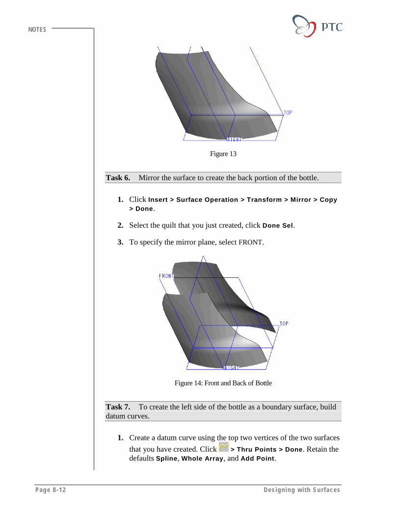
Page 8-12 Des igning w i th Surfaces
NOTES
Figure 13
Task 6. Mirror the surface to create the back portion of the bottle.
1. Click Insert > Surface Operation > Transform > Mirror > Copy> Done.
2. Select the quilt that you just created, click Done Sel.
3. To specify the mirror plane, select FRONT.
Figure 14: Front and Back of Bottle
Task 7. To create the left side of the bottle as a boundary surface, builddatum curves.
1. Create a datum curve using the top two vertices of the two surfaces
that you have created. Click > Thru Points > Done. Retain thedefaults Spline, Whole Array, and Add Point.
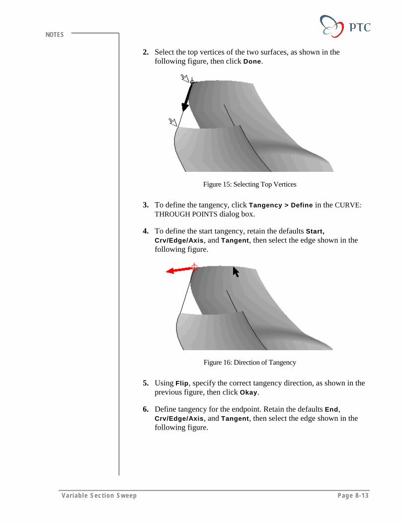
Var iab le Sect ion Sweep Page 8-13
NOTES
2. Select the top vertices of the two surfaces, as shown in thefollowing figure, then click Done.
Figure 15: Selecting Top Vertices
3. To define the tangency, click Tangency > Define in the CURVE:THROUGH POINTS dialog box.
4. To define the start tangency, retain the defaults Start,Crv/Edge/Axis, and Tangent, then select the edge shown in thefollowing figure.
Figure 16: Direction of Tangency
5. Using Flip, specify the correct tangency direction, as shown in theprevious figure, then click Okay.
6. Define tangency for the endpoint. Retain the defaults End,Crv/Edge/Axis, and Tangent, then select the edge shown in thefollowing figure.
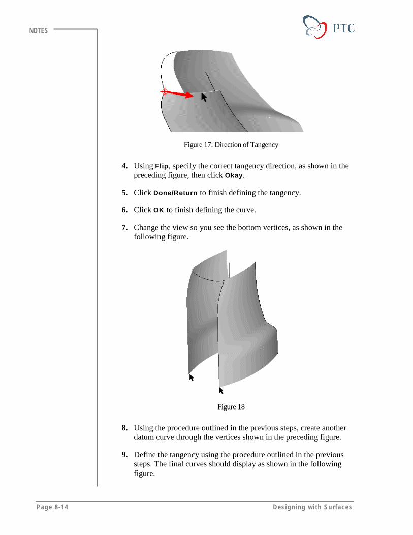
Page 8-14 Des igning w i th Surfaces
NOTES
Figure 17: Direction of Tangency
4. Using Flip, specify the correct tangency direction, as shown in thepreceding figure, then click Okay.
5. Click Done/Return to finish defining the tangency.
6. Click OK to finish defining the curve.
7. Change the view so you see the bottom vertices, as shown in thefollowing figure.
Figure 18
8. Using the procedure outlined in the previous steps, create anotherdatum curve through the vertices shown in the preceding figure.
9. Define the tangency using the procedure outlined in the previoussteps. The final curves should display as shown in the followingfigure.

Var iab le Sect ion Sweep Page 8-15
NOTES
Figure 19
Tips & Techniques:
If you specified the direction incorrectly, or, you cannotremember which one was the start point, you can redefine thetangency by clicking Start or End, selecting thecorresponding edge once more, and clicking Flip and OK.
Task 8. Create a surface by boundaries. Make it tangential to theadjacent surfaces.
1. Click Insert > Surface > From Boundaries > Blended Surf >Done to create a blended surface by boundaries.
2. Specify the curves in the first direction. Retain the defaults FirstDir, Add Item, and Curve, then select the two datum curves.
3. Define the first curve of the second direction. Click Second Dirand retain the default Add Item, then click Chain > TangentChain > Select. Select the edge of one of the surface, then clickDone.
Tips & Technique:
It is always good practice to use the edge of the adjacentsurface instead of that surface’s defining curves.
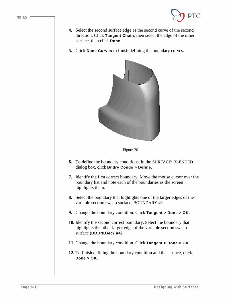
Page 8-16 Des igning w i th Surfaces
NOTES
4. Select the second surface edge as the second curve of the seconddirection. Click Tangent Chain, then select the edge of the othersurface, then click Done.
5. Click Done Curves to finish defining the boundary curves.
Figure 20
6. To define the boundary conditions, in the SURFACE: BLENDEDdialog box, click Bndry Conds > Define.
7. Identify the first correct boundary. Move the mouse cursor over theboundary list and note each of the boundaries as the screenhighlights them.
8. Select the boundary that highlights one of the larger edges of thevariable section sweep surface, BOUNDARY #3.
9. Change the boundary condition. Click Tangent > Done > OK.
10. Identify the second correct boundary. Select the boundary thathighlights the other larger edge of the variable section sweepsurface (BOUNDARY #4).
11. Change the boundary condition. Click Tangent > Done > OK.
12. To finish defining the boundary condition and the surface, clickDone > OK.
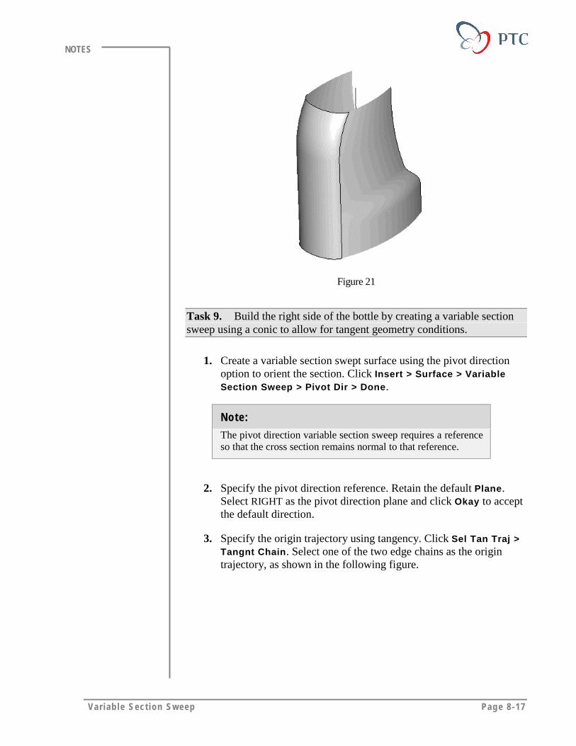
Var iab le Sect ion Sweep Page 8-17
NOTES
Figure 21
Task 9. Build the right side of the bottle by creating a variable sectionsweep using a conic to allow for tangent geometry conditions.
1. Create a variable section swept surface using the pivot directionoption to orient the section. Click Insert > Surface > VariableSection Sweep > Pivot Dir > Done.
Note:
The pivot direction variable section sweep requires a referenceso that the cross section remains normal to that reference.
2. Specify the pivot direction reference. Retain the default Plane.Select RIGHT as the pivot direction plane and click Okay to acceptthe default direction.
3. Specify the origin trajectory using tangency. Click Sel Tan Traj >Tangnt Chain. Select one of the two edge chains as the origintrajectory, as shown in the following figure.

Page 8-18 Des igning w i th Surfaces
NOTES
Figure 22
4. Specify the start of the trajectory. Confirm that the start point ofthe sweep is at the bottom, as shown in the following figure. Ifnecessary, click Start Point > Next to change the location, thenclick Accept.
Figure 23
5. Click Done to finish defining the origin trajectory.
6. To define highlighted surface as tangent, click Accept.
7. Click Join > Done to merge the new surface with the existingsurface.
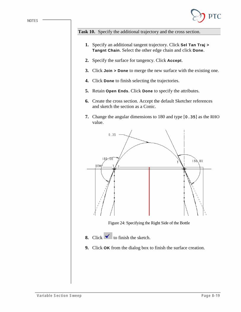
Var iab le Sect ion Sweep Page 8-19
NOTES
Task 10. Specify the additional trajectory and the cross section.
1. Specify an additional tangent trajectory. Click Sel Tan Traj >Tangnt Chain. Select the other edge chain and click Done.
2. Specify the surface for tangency. Click Accept.
3. Click Join > Done to merge the new surface with the existing one.
4. Click Done to finish selecting the trajectories.
5. Retain Open Ends. Click Done to specify the attributes.
6. Create the cross section. Accept the default Sketcher referencesand sketch the section as a Conic.
7. Change the angular dimensions to 180 and type [0.35] as the RHOvalue.
Figure 24: Specifying the Right Side of the Bottle
8. Click to finish the sketch.
9. Click OK from the dialog box to finish the surface creation.

Page 8-20 Des igning w i th Surfaces
NOTES
Figure 25
Task 11. Redefine the surface that you just created in order to control theshape of the cross section using the trajpar parameter and a graph.
1. Select the surface that you just created and right-click Redefine.
2. To add relation in the conic parameter, click Section > Define >Sketch in the SURFACE: VARIABLE SECTION SWEEP dialogbox.
Figure 26: Predefined Conic Graph
3. To drive the RHO value from the graph, click Sketch > Relations> Add.
4. Note that the sketch now shows the symbolic dimensioninformation. Type the relation [sd# = evalgraph (“CONIC”,trajpar * 10) / 10], where SD# is the symbol for the RHOdimension
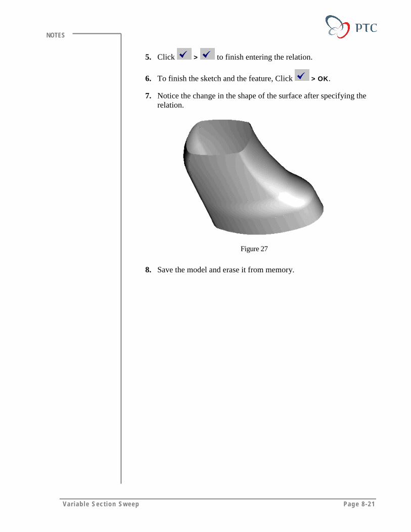
Var iab le Sect ion Sweep Page 8-21
NOTES
5. Click > to finish entering the relation.
6. To finish the sketch and the feature, Click > OK.
7. Notice the change in the shape of the surface after specifying therelation.
Figure 27
8. Save the model and erase it from memory.
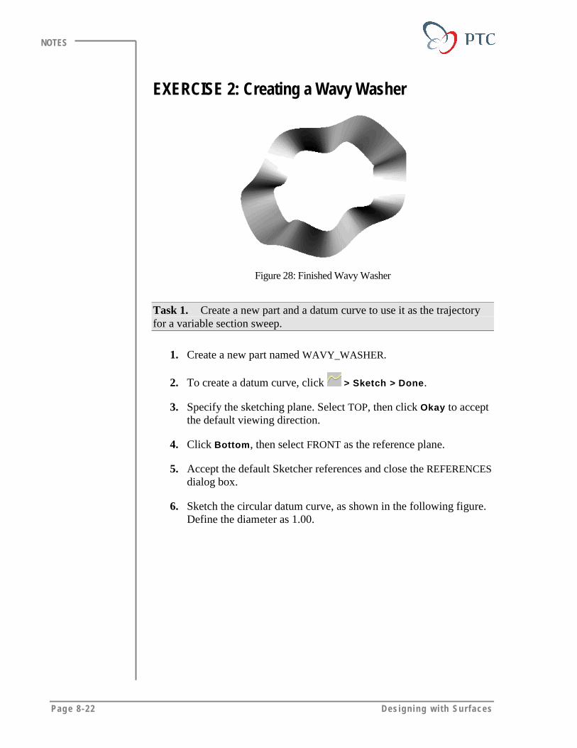
Page 8-22 Des igning w i th Surfaces
NOTES
EXERCISE 2: Creating a Wavy Washer
Figure 28: Finished Wavy Washer
Task 1. Create a new part and a datum curve to use it as the trajectoryfor a variable section sweep.
1. Create a new part named WAVY_WASHER.
2. To create a datum curve, click > Sketch > Done.
3. Specify the sketching plane. Select TOP, then click Okay to acceptthe default viewing direction.
4. Click Bottom, then select FRONT as the reference plane.
5. Accept the default Sketcher references and close the REFERENCESdialog box.
6. Sketch the circular datum curve, as shown in the following figure.Define the diameter as 1.00.
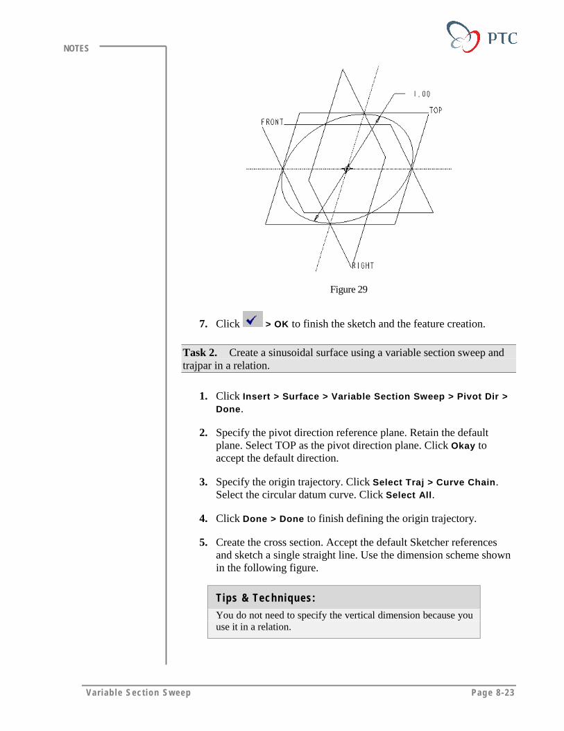
Var iab le Sect ion Sweep Page 8-23
NOTES
Figure 29
7. Click > OK to finish the sketch and the feature creation.
Task 2. Create a sinusoidal surface using a variable section sweep andtrajpar in a relation.
1. Click Insert > Surface > Variable Section Sweep > Pivot Dir >Done.
2. Specify the pivot direction reference plane. Retain the defaultplane. Select TOP as the pivot direction plane. Click Okay toaccept the default direction.
3. Specify the origin trajectory. Click Select Traj > Curve Chain.Select the circular datum curve. Click Select All.
4. Click Done > Done to finish defining the origin trajectory.
5. Create the cross section. Accept the default Sketcher referencesand sketch a single straight line. Use the dimension scheme shownin the following figure.
Tips & Techniques:
You do not need to specify the vertical dimension because youuse it in a relation.

Page 8-24 Des igning w i th Surfaces
NOTES
Figure 30
6. To add a relation click Sketch > Relation > Add. Type therelation [sd# = sin(trajpar*360*6)/20], where SD# is thevertical dimension.
7. Click > to finish entering the relation.
8. Click to complete the sketch.
9. Click OK to complete the feature.
10. Save the model and erase it from memory.
Var iab le Sect ion Sweep Page 8-25
NOTES
MODULE SUMMARYIn this module, you have learned that:
• The variable section sweeps allow you to create complex geometrywith tight control.
• You control the shape of a section using a graph.
• You control the shape of the resultant geometry using a trajectoryparameter known as trajpar.

Page 9-1
Module
Swept BlendsIn this module you learn to create surfaces using the Swept Blend
tool.
Objectives
After completing this module, you will be able to:
• Create surfaces using the Swept Blend tool.
• Manipulate the shape of swept blend surfaces using differenttechniques.
• Define and control the relation between sections and the trajectory.
• Define limitations on the swept blend surfaces.
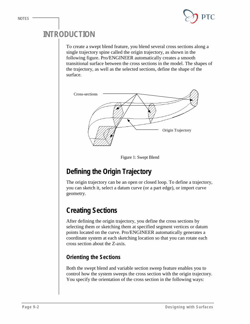
Page 9-2 Des igning w i th Surfaces
NOTES
INTRODUCTIONTo create a swept blend feature, you blend several cross sections along asingle trajectory spine called the origin trajectory, as shown in thefollowing figure. Pro/ENGINEER automatically creates a smoothtransitional surface between the cross sections in the model. The shapes ofthe trajectory, as well as the selected sections, define the shape of thesurface.
Cross-sections
Origin Trajectory
Figure 1: Swept Blend
Defining the Origin TrajectoryThe origin trajectory can be an open or closed loop. To define a trajectory,you can sketch it, select a datum curve (or a part edge), or import curvegeometry.
Creating SectionsAfter defining the origin trajectory, you define the cross sections byselecting them or sketching them at specified segment vertices or datumpoints located on the curve. Pro/ENGINEER automatically generates acoordinate system at each sketching location so that you can rotate eachcross section about the Z-axis.
Orienting the Sections
Both the swept blend and variable section sweep feature enables you tocontrol how the system sweeps the cross section with the origin trajectory.You specify the orientation of the cross section in the following ways:
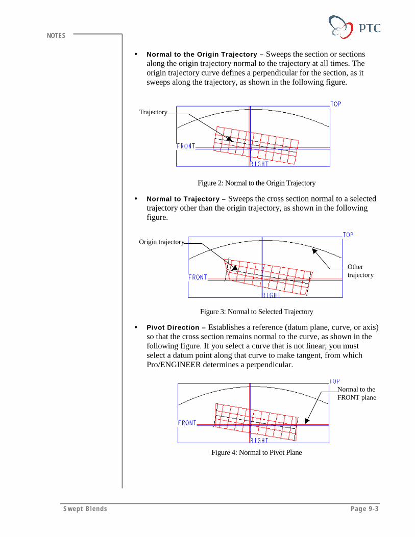
Swept B lends Page 9-3
NOTES
• Normal to the Origin Trajectory – Sweeps the section or sectionsalong the origin trajectory normal to the trajectory at all times. Theorigin trajectory curve defines a perpendicular for the section, as itsweeps along the trajectory, as shown in the following figure.
Trajectory
Figure 2: Normal to the Origin Trajectory
• Normal to Trajectory – Sweeps the cross section normal to a selectedtrajectory other than the origin trajectory, as shown in the followingfigure.
Origin trajectory
Othertrajectory
Figure 3: Normal to Selected Trajectory
• Pivot Direction – Establishes a reference (datum plane, curve, or axis)so that the cross section remains normal to the curve, as shown in thefollowing figure. If you select a curve that is not linear, you mustselect a datum point along that curve to make tangent, from whichPro/ENGINEER determines a perpendicular.
Normal to theFRONT plane
Figure 4: Normal to Pivot Plane
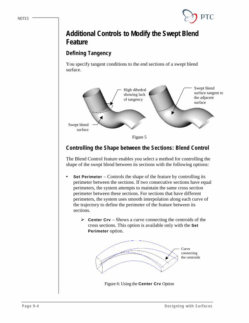
Page 9-4 Des igning w i th Surfaces
NOTES
Additional Controls to Modify the Swept BlendFeatureDefining Tangency
You specify tangent conditions to the end sections of a swept blendsurface.
Swept blendsurface tangent tothe adjacentsurface
Swept blendsurface
High dihedralshowing lackof tangency
Figure 5
Controlling the Shape between the Sections: Blend Control
The Blend Control feature enables you select a method for controlling theshape of the swept blend between its sections with the following options:
• Set Perimeter – Controls the shape of the feature by controlling itsperimeter between the sections. If two consecutive sections have equalperimeters, the system attempts to maintain the same cross sectionperimeter between these sections. For sections that have differentperimeters, the system uses smooth interpolation along each curve ofthe trajectory to define the perimeter of the feature between itssections.
� Center Crv – Shows a curve connecting the centroids of thecross sections. This option is available only with the SetPerimeter option.
Curveconnectingthe centroids
Figure 6: Using the Center Crv Option
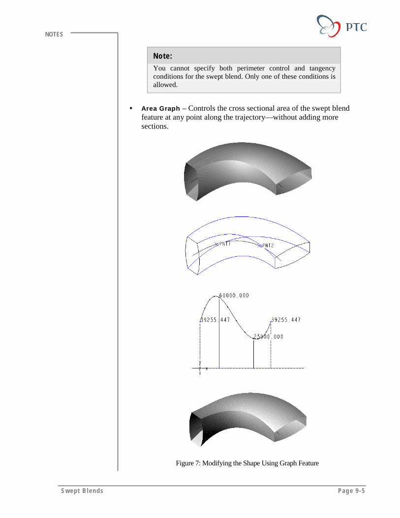
Swept B lends Page 9-5
NOTES
Note:
You cannot specify both perimeter control and tangencyconditions for the swept blend. Only one of these conditions isallowed.
• Area Graph – Controls the cross sectional area of the swept blendfeature at any point along the trajectory—without adding moresections.
Figure 7: Modifying the Shape Using Graph Feature
Page 9-6 Des igning w i th Surfaces
NOTES
Restrictions on Swept BlendsTo create a swept blend, all sections must intersect the trajectory with thefollowing restrictions:
• To create a closed trajectory, you use two sections: one sketched at thestart point and the other sketched at any other location.
• To create an open trajectory, you use a section at the start points andendpoints.
• You cannot select composite datum curves to define sections of aswept blend. Instead, you use the underlying curve segments or edgesfrom the composite curve.

Swept B lends Page 9-7
NOTES
LABORATORY PRACTICALGoal
In this laboratory you create a swept blend surface feature and modify
the shape using a graph.
Method
In this exercise you create a MANIFOLD part using pre-constructedtrajectory and a rectangle section. To create the swept blend surface, youdefine the other section as a circle, locate the points where you want tochange the section area, then modify the area using a graph.
ToolsIcon Description
Saved View List
Insert Datum Curve
Select Geometry
Insert a Feature
Select Primary Items
Build Feature
Done
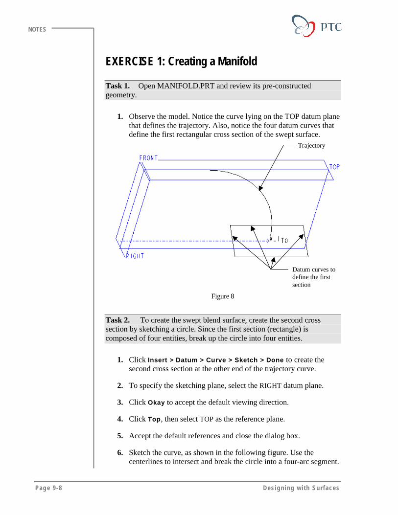
Page 9-8 Des igning w i th Surfaces
NOTES
EXERCISE 1: Creating a Manifold
Task 1. Open MANIFOLD.PRT and review its pre-constructedgeometry.
1. Observe the model. Notice the curve lying on the TOP datum planethat defines the trajectory. Also, notice the four datum curves thatdefine the first rectangular cross section of the swept surface.
Trajectory
Datum curves todefine the firstsection
Figure 8
Task 2. To create the swept blend surface, create the second crosssection by sketching a circle. Since the first section (rectangle) iscomposed of four entities, break up the circle into four entities.
1. Click Insert > Datum > Curve > Sketch > Done to create thesecond cross section at the other end of the trajectory curve.
2. To specify the sketching plane, select the RIGHT datum plane.
3. Click Okay to accept the default viewing direction.
4. Click Top, then select TOP as the reference plane.
5. Accept the default references and close the dialog box.
6. Sketch the curve, as shown in the following figure. Use thecenterlines to intersect and break the circle into a four-arc segment.

Swept B lends Page 9-9
NOTES
Figure 9
7. Click > OK to finish the sketch and the curve creation
Task 3. Construct the manifold surface using a normal to origintrajectory.
1. Click Insert > Surface > Swept Blend. In BLENDS OPTS menu,click Select Sec > NrmToOriginTraj > Done.
2. Specify the origin trajectory. Click Select Traj > Curve Chain.Select the trajectory shown in the following figure, then clickSelect All.
3. Confirm that the start point is at the end close to the rectanglesection, as shown in the following figure. Otherwise, change thelocation of the start point. Click Done.
Select thiscurve astrajectory
Start point
Figure 10

Page 9-10 Des igning w i th Surfaces
NOTES
4. To specify the attributes, click Open Ends > Done.
5. To specify the first cross section, retain the default Pick Curve andclick Sel Loop. Select the rectangular datum curve as the firstsection. Click Done Sel > Done/Return.
6. Note the location of the start point.
7. Click Done to finish defining the first cross section.
8. Specify the circular curve for the second cross section. Retain PickCurve as the default. Click Sel Loop.
9. Select the circular datum curve as the second section, then clickDone Sel > Done/Return.
10. To avoid twisting, if necessary, change the start point. Click StartPoint, then select the correct vertex on the circular cross section.Click Done.
11. Finish creating the swept blend. When the system prompts you tospecify another section, click NO, then click OK from the dialogbox.
Figure 11
Task 4. Create a flat surface to start the definition of the mountingflange for the manifold
1. Click Insert > Surface > Flat > Done to create a flat surface.
2. To specify the sketching plane, click Make Datum > Through,then select one of the long edges at the rectangular start of theswept blend.
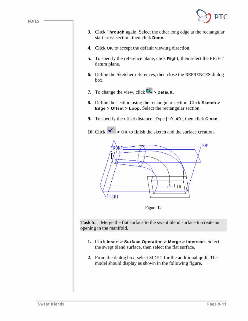
Swept B lends Page 9-11
NOTES
3. Click Through again. Select the other long edge at the rectangularstart cross section, then click Done.
4. Click OK to accept the default viewing direction.
5. To specify the reference plane, click Right, then select the RIGHTdatum plane.
6. Define the Sketcher references, then close the REFRENCES dialogbox.
7. To change the view, click > Default.
8. Define the section using the rectangular section. Click Sketch >Edge > Offset > Loop. Select the rectangular section.
9. To specify the offset distance. Type [-0.40], then click Close.
10. Click > OK to finish the sketch and the surface creation.
Figure 12
Task 5. Merge the flat surface to the swept blend surface to create anopening in the manifold.
1. Click Insert > Surface Operation > Merge > Intersect. Selectthe swept blend surface, then select the flat surface.
2. From the dialog box, select SIDE 2 for the additional quilt. Themodel should display as shown in the following figure.
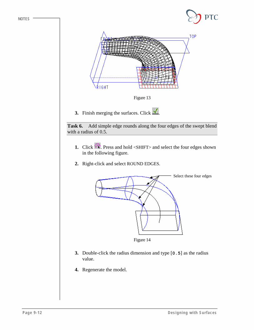
Page 9-12 Des igning w i th Surfaces
NOTES
Figure 13
3. Finish merging the surfaces. Click .
Task 6. Add simple edge rounds along the four edges of the swept blendwith a radius of 0.5.
1. Click . Press and hold <SHIFT> and select the four edges shownin the following figure.
2. Right-click and select ROUND EDGES.
Select these four edges
Figure 14
3. Double-click the radius dimension and type [0.5] as the radiusvalue.
4. Regenerate the model.
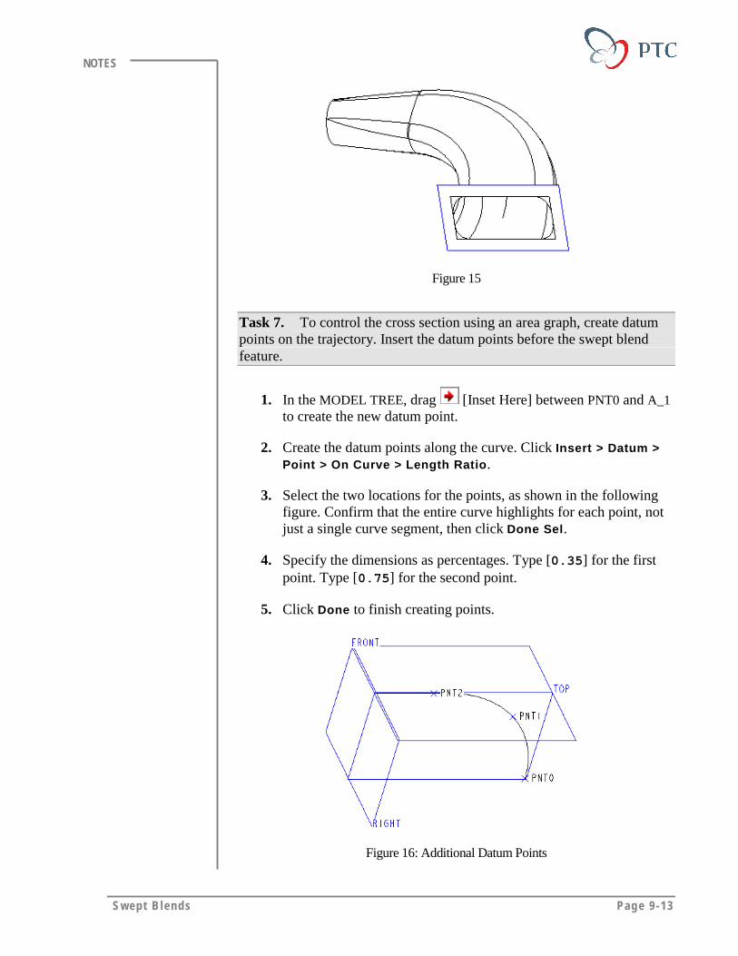
Swept B lends Page 9-13
NOTES
Figure 15
Task 7. To control the cross section using an area graph, create datumpoints on the trajectory. Insert the datum points before the swept blendfeature.
1. In the MODEL TREE, drag [Inset Here] between PNT0 and A_1to create the new datum point.
2. Create the datum points along the curve. Click Insert > Datum >Point > On Curve > Length Ratio.
3. Select the two locations for the points, as shown in the followingfigure. Confirm that the entire curve highlights for each point, notjust a single curve segment, then click Done Sel.
4. Specify the dimensions as percentages. Type [0.35] for the firstpoint. Type [0.75] for the second point.
5. Click Done to finish creating points.
Figure 16: Additional Datum Points

Page 9-14 Des igning w i th Surfaces
NOTES
6. To resume all suppressed features, drag [Insert Here] to thebottom of the Model Tree.
Task 8. Use area graph to control the shape of the cross section at thelocation where you have created the points. Redefine the swept blendfeature.
1. Click and select the swept blend from the model. Click Edit >Definition.
2. Define the blend control. Click Blend Control > Define > AreaGraph > Done/Return. The system will open a second windowdisplaying the existing area of the current model.
Tips & Techniques:
You can also use Set Perimeter to vary the perimeter of thecross sections.
Figure 17: Existing Area Graph of the Swept Blend
3. Add the first datum point to the graph. Retain the defaults Define,Add Point, and Select Point. Select the datum point PNT1 closestto the rectangular end.
4. Define the new area value. Type [3.00] and click . Observe thechange in the graph.
5. Modify area at the second point. Select the datum point PNT2
closest to the circular end. Type [2.25] and click .

Swept B lends Page 9-15
NOTES
6. Click Done Sel > Done/Return > Done/Return > Done > OK tofinish the changes to the area graph and the complete the featurecreation.
Figure 18: Changes Resulting from Different Area Graph
Task 9. Modify the area graph dimension again.
1. Click Modify and select the swept blend. Click All.
2. Modify the dimensions 3.00 to 5.00 and 2.25 to 3.00, asshown in the following figure.
Figure 19
3. Regenerate the model and observe the change.
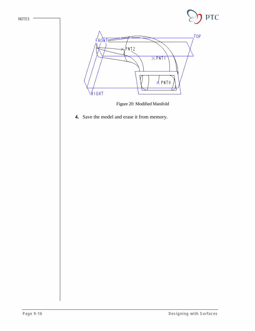
Page 9-16 Des igning w i th Surfaces
NOTES
Figure 20: Modified Manifold
4. Save the model and erase it from memory.
Swept B lends Page 9-17
NOTES
MODULE SUMMARYIn this module, you have learned that:
• A swept blend is defined by sweeping many sections (at least two),over a trajectory.
• To create a swept blend feature, you must have the same number ofentities in each section.
• You manipulate the area of a specified cross section using a graph,without having to introduce a specific section.


Page 10-1
Module
Surface Information & AnalysisIn this module, you learn how to use surface analysis tools.
Objectives
After completing this module, you will be able to:
• Define the need to analyze surfaces.
• Analyze surfaces using different tools.
Page 10-2 Des igning w i th Surfaces
NOTES
ANALYZING GEOMETRYObtaining information on surface geometry during the design processhelps you to analyze:
• Surface quality of imported surfaces.
• Surface continuities.
• Reasons for failure of some surface operations.
• Aesthetic qualities of a design.
The wireframe and shaded model may not provide accurate informationabout the surfaces. Pro/ENGINEER offers a number of tools to analyzeand obtain the information about the model geometry.
Fringe Plot Analysis
For some types of analysis, you use fringe plots on the model to shadeselected surfaces in colors to represent values in a color range.
Fringe Plot Colors – Hot colors of the spectrum represent large positivevalues, whereas the cool colors, such as blue, represent highly negativevalues.
Using fringe plot analysis, you can extract information and analyze asurface by using any of the following tools:
• Gaussian Curvature
• Section Curvature
• Slope
• Draft Angle
Other Surface Analysis Tools
The following tools are not as graphics-intensive as the fringe plot; theyprovide plots or numerical results:
• Porcupine
• Normals
• Deviation
• Reflection Curves
• Radius
• Offset Mesh
• Highlight Curves
• Information at a Point
• Dihedral Angle
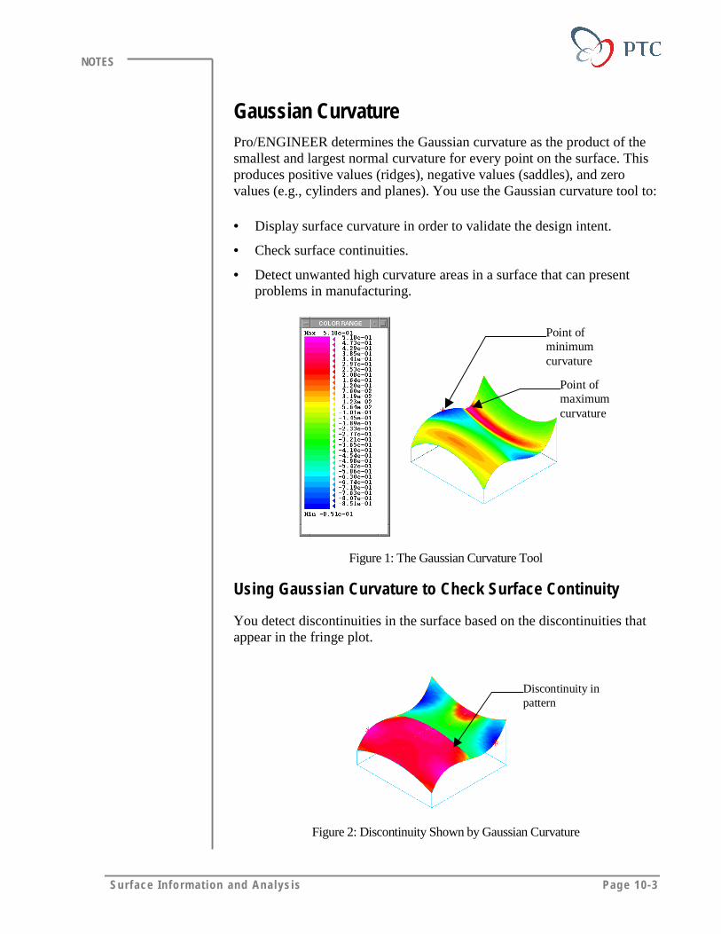
Surface Info rm at ion and Ana lys is Page 10-3
NOTES
Gaussian CurvaturePro/ENGINEER determines the Gaussian curvature as the product of thesmallest and largest normal curvature for every point on the surface. Thisproduces positive values (ridges), negative values (saddles), and zerovalues (e.g., cylinders and planes). You use the Gaussian curvature tool to:
• Display surface curvature in order to validate the design intent.
• Check surface continuities.
• Detect unwanted high curvature areas in a surface that can presentproblems in manufacturing.
Point ofmaximumcurvature
Point ofminimumcurvature
Figure 1: The Gaussian Curvature Tool
Using Gaussian Curvature to Check Surface Continuity
You detect discontinuities in the surface based on the discontinuities thatappear in the fringe plot.
Discontinuity inpattern
Figure 2: Discontinuity Shown by Gaussian Curvature
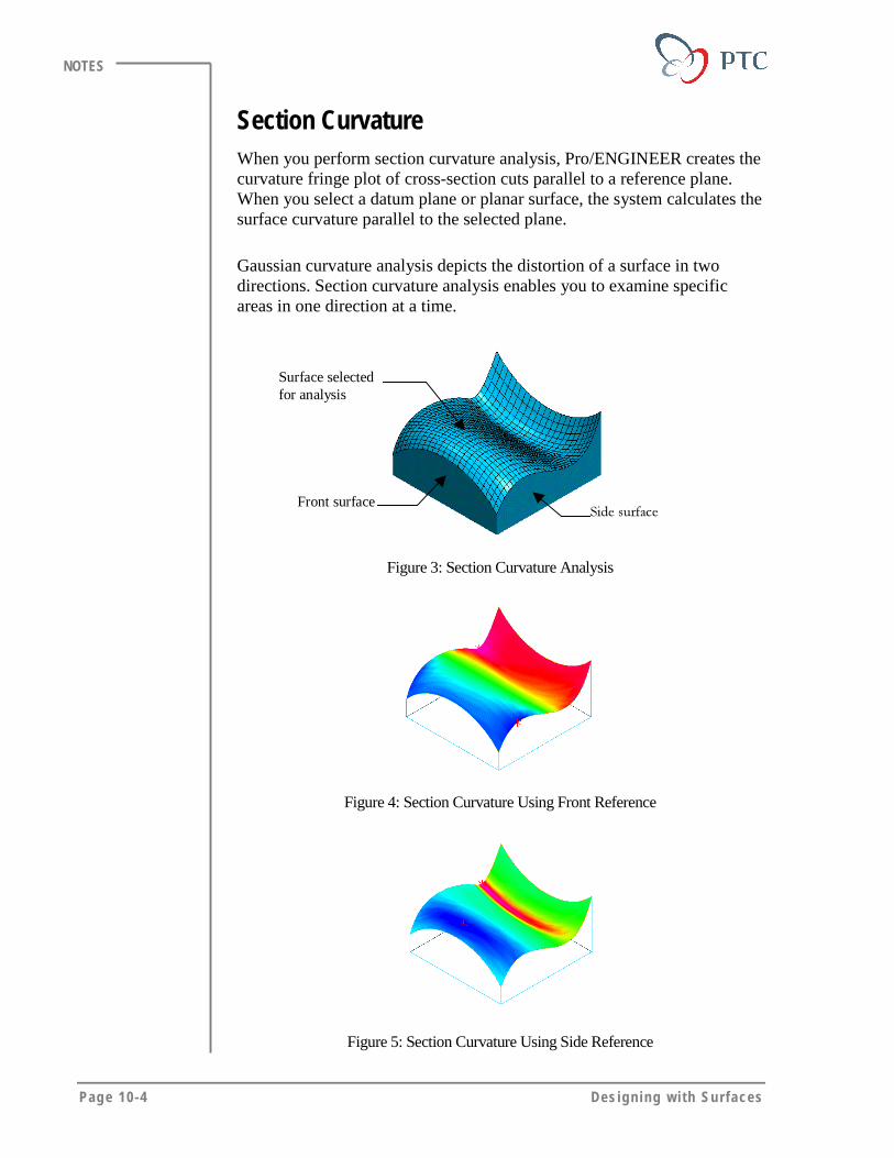
Page 10-4 Des igning w i th Surfaces
NOTES
Section CurvatureWhen you perform section curvature analysis, Pro/ENGINEER creates thecurvature fringe plot of cross-section cuts parallel to a reference plane.When you select a datum plane or planar surface, the system calculates thesurface curvature parallel to the selected plane.
Gaussian curvature analysis depicts the distortion of a surface in twodirections. Section curvature analysis enables you to examine specificareas in one direction at a time.
Surface selectedfor analysis
Front surface����������
Figure 3: Section Curvature Analysis
Figure 4: Section Curvature Using Front Reference
Figure 5: Section Curvature Using Side Reference
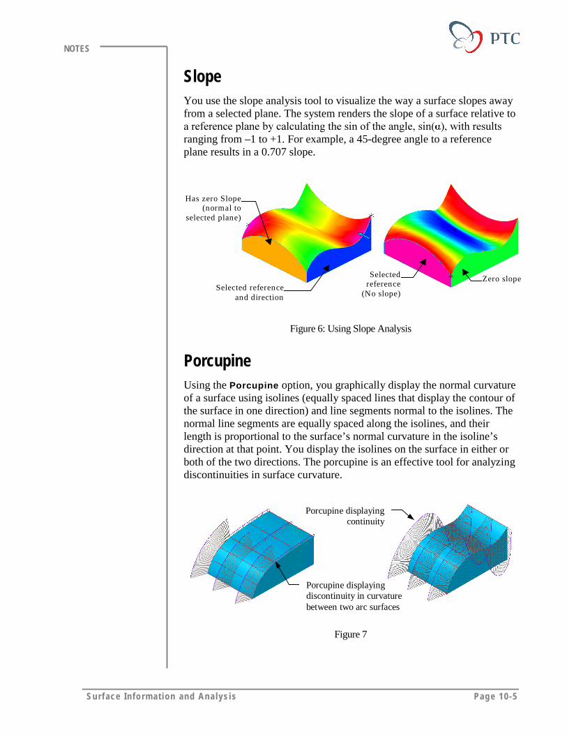
Surface Info rm at ion and Ana lys is Page 10-5
NOTES
SlopeYou use the slope analysis tool to visualize the way a surface slopes awayfrom a selected plane. The system renders the slope of a surface relative to������������������������ ���� ���������� ������������� ����� ������ �ranging from –1 to +1. For example, a 45-degree angle to a referenceplane results in a 0.707 slope.
Has zero Slope(normal to
selected plane)
Selected referenceand direction
Selectedreference
(No slope)
Zero slope
Figure 6: Using Slope Analysis
PorcupineUsing the Porcupine option, you graphically display the normal curvatureof a surface using isolines (equally spaced lines that display the contour ofthe surface in one direction) and line segments normal to the isolines. Thenormal line segments are equally spaced along the isolines, and theirlength is proportional to the surface’s normal curvature in the isoline’sdirection at that point. You display the isolines on the surface in either orboth of the two directions. The porcupine is an effective tool for analyzingdiscontinuities in surface curvature.
Porcupine displayingdiscontinuity in curvaturebetween two arc surfaces
Porcupine displayingcontinuity
Figure 7
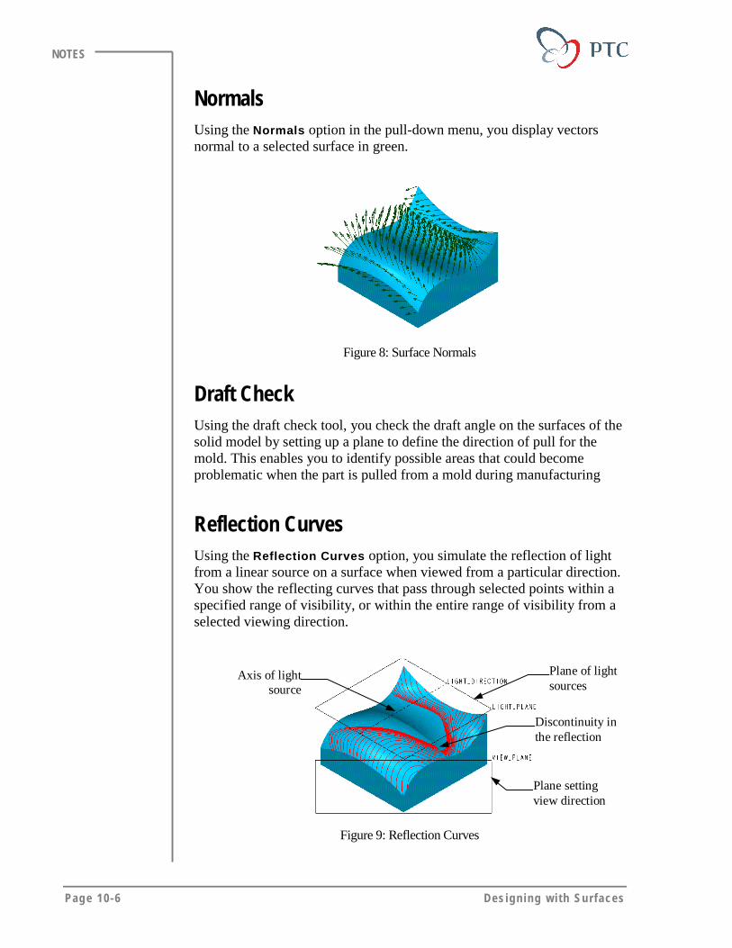
Page 10-6 Des igning w i th Surfaces
NOTES
NormalsUsing the Normals option in the pull-down menu, you display vectorsnormal to a selected surface in green.
Figure 8: Surface Normals
Draft CheckUsing the draft check tool, you check the draft angle on the surfaces of thesolid model by setting up a plane to define the direction of pull for themold. This enables you to identify possible areas that could becomeproblematic when the part is pulled from a mold during manufacturing
Reflection CurvesUsing the Reflection Curves option, you simulate the reflection of lightfrom a linear source on a surface when viewed from a particular direction.You show the reflecting curves that pass through selected points within aspecified range of visibility, or within the entire range of visibility from aselected viewing direction.
Axis of lightsource
Plane of lightsources
Plane settingview direction
Discontinuity inthe reflection
Figure 9: Reflection Curves

Surface Info rm at ion and Ana lys is Page 10-7
NOTES
RadiusUsing the Radius option, you determine the minimum and maximumradius of a surface.
Point of outsideminimum radius
Figure 10: Determining the Minimum Radius
Offset MeshUsing the Offset Mesh option, you create a mesh offset from a selectedsurface, which is useful for exaggerating slight changes to check thequality of the surface. Visible cusps in the offset mesh show a radius ofcurvature smaller than the offset distance. This tool is useful forinterrogating geometry that fails when creating thin protrusions or shells.
Figure 11: Creating an Offset Mesh

Page 10-8 Des igning w i th Surfaces
NOTES
DeviationUsing the Deviation option, you analyze the deviation between differententities and the model surface using surface normals. This tool providesthe maximum and minimum distance between the selected references. Youcan enter a tolerance value to identify where the surface is out of toleranceto the selected entity. You select datum curves, datum points (a single oneor point array) and scan curves. This tool can be helpful when you areusing imported data to create geometry, such as imported curves or points.
Highlight CurvesUsing the Highlight Curves option, you create curves on a surface withcertain values of slope to a selected planar reference. You select pointsmanually on the surface or enter incremental degree values.
If you select the points manually, the system creates curves through thesurface at locations with the same slope as the selected point. If you enterangular increments, it creates highlight lines for each angular increment.This tool is useful for illustrating how a surface is contoured.
Selected reference using5-degree increments
Figure 12: Using Highlight Curves Tool
Information at a Certain PointUsing the Info at Point option, you extract information that provides thecoordinates, the unit normal and the unit direction vectors in a coordinatesystem; the signed principal curvatures at a point on a surface; theprincipal radii of curvature; and the product of the curvatures. Thisinformation can be useful when the design requires you to know exactinformation at a specified point. You can save the analysis for future use.

Surface Info rm at ion and Ana lys is Page 10-9
NOTES
Dihedral AngleThe Dihedral Angle option measures the angles between the tangents ofthe adjoining surfaces along the common edge. This tool is useful fordetermining if two surfaces are tangent (G1) or not, or the extent to whichthey are not tangent.
Selectededge
Point ofmaximumdihedral angle
Point of minimumdihedral angle
Figure 13
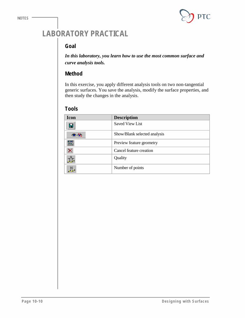
Page 10-10 Des igning w i th Surfaces
NOTES
LABORATORY PRACTICALGoal
In this laboratory, you learn how to use the most common surface and
curve analysis tools.
Method
In this exercise, you apply different analysis tools on two non-tangentialgeneric surfaces. You save the analysis, modify the surface properties, andthen study the changes in the analysis.
ToolsIcon Description
Saved View List
Show/Blank selected analysis
Preview feature geometry
Cancel feature creation
Quality
Number of points
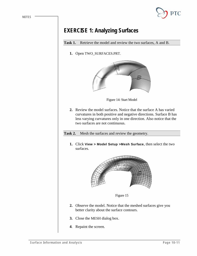
Surface Info rm at ion and Ana lys is Page 10-11
NOTES
EXERCISE 1: Analyzing Surfaces
Task 1. Retrieve the model and review the two surfaces, A and B.
1. Open TWO_SURFACES.PRT.
Figure 14: Start Model
2. Review the model surfaces. Notice that the surface A has variedcurvatures in both positive and negative directions. Surface B hasless varying curvatures only in one direction. Also notice that thetwo surfaces are not continuous.
Task 2. Mesh the surfaces and review the geometry.
1. Click View > Model Setup >Mesh Surface, then select the twosurfaces.
Figure 15
2. Observe the model. Notice that the meshed surfaces give youbetter clarity about the surface contours.
3. Close the MESH dialog box.
4. Repaint the screen.
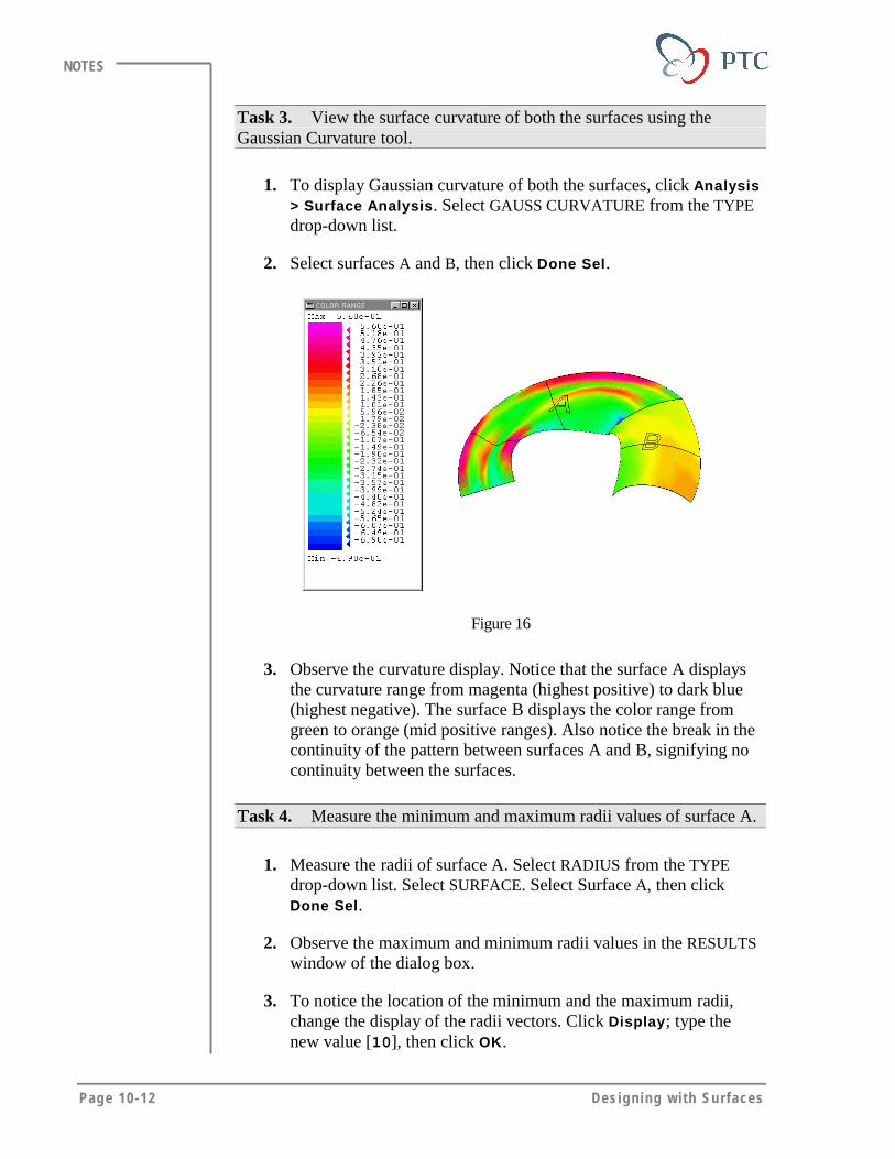
Page 10-12 Des igning w i th Surfaces
NOTES
Task 3. View the surface curvature of both the surfaces using theGaussian Curvature tool.
1. To display Gaussian curvature of both the surfaces, click Analysis> Surface Analysis. Select GAUSS CURVATURE from the TYPEdrop-down list.
2. Select surfaces A and B, then click Done Sel.
Figure 16
3. Observe the curvature display. Notice that the surface A displaysthe curvature range from magenta (highest positive) to dark blue(highest negative). The surface B displays the color range fromgreen to orange (mid positive ranges). Also notice the break in thecontinuity of the pattern between surfaces A and B, signifying nocontinuity between the surfaces.
Task 4. Measure the minimum and maximum radii values of surface A.
1. Measure the radii of surface A. Select RADIUS from the TYPEdrop-down list. Select SURFACE. Select Surface A, then clickDone Sel.
2. Observe the maximum and minimum radii values in the RESULTSwindow of the dialog box.
3. To notice the location of the minimum and the maximum radii,change the display of the radii vectors. Click Display; type thenew value [10], then click OK.
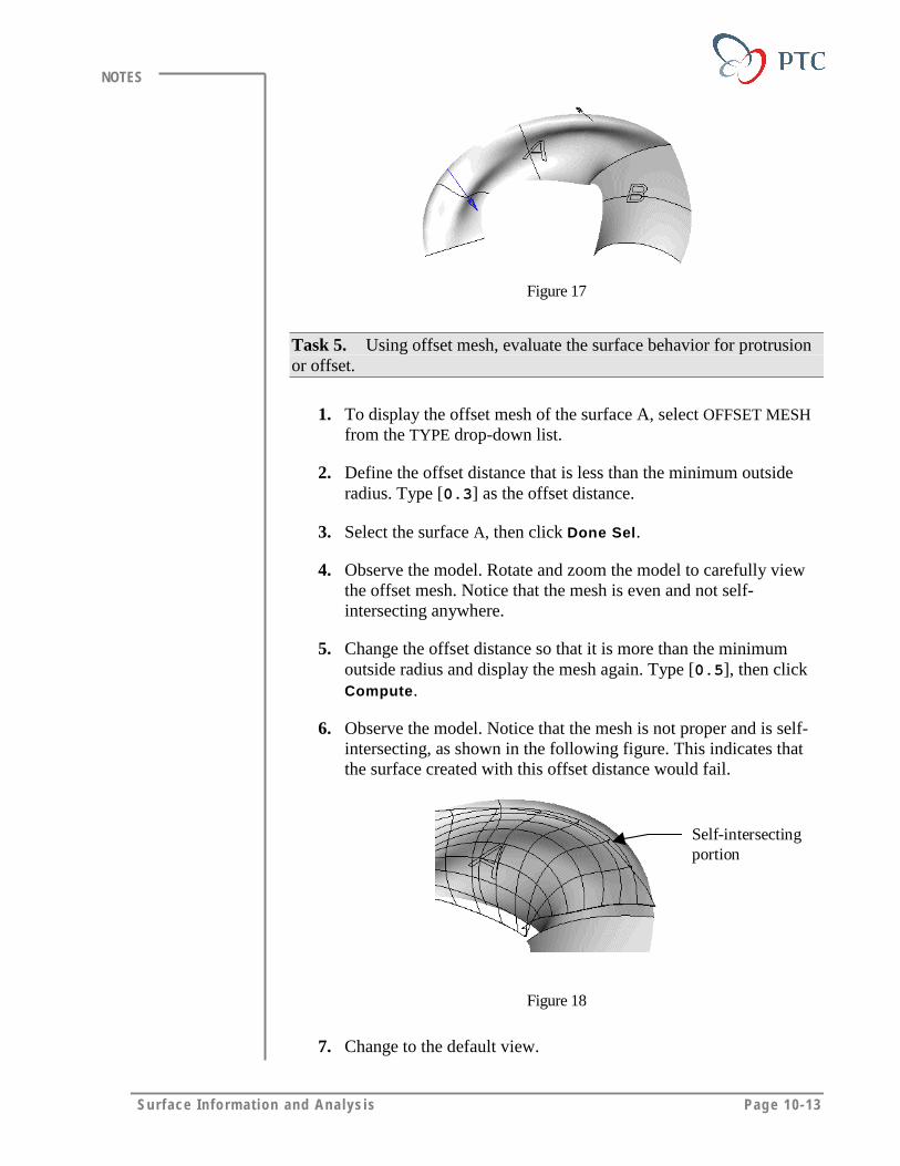
Surface Info rm at ion and Ana lys is Page 10-13
NOTES
Figure 17
Task 5. Using offset mesh, evaluate the surface behavior for protrusionor offset.
1. To display the offset mesh of the surface A, select OFFSET MESHfrom the TYPE drop-down list.
2. Define the offset distance that is less than the minimum outsideradius. Type [0.3] as the offset distance.
3. Select the surface A, then click Done Sel.
4. Observe the model. Rotate and zoom the model to carefully viewthe offset mesh. Notice that the mesh is even and not self-intersecting anywhere.
5. Change the offset distance so that it is more than the minimumoutside radius and display the mesh again. Type [0.5], then clickCompute.
6. Observe the model. Notice that the mesh is not proper and is self-intersecting, as shown in the following figure. This indicates thatthe surface created with this offset distance would fail.
Self-intersectingportion
Figure 18
7. Change to the default view.
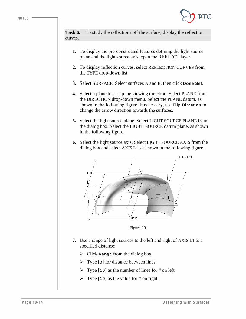
Page 10-14 Des igning w i th Surfaces
NOTES
Task 6. To study the reflections off the surface, display the reflectioncurves.
1. To display the pre-constructed features defining the light sourceplane and the light source axis, open the REFLECT layer.
2. To display reflection curves, select REFLECTION CURVES fromthe TYPE drop-down list.
3. Select SURFACE. Select surfaces A and B, then click Done Sel.
4. Select a plane to set up the viewing direction. Select PLANE fromthe DIRECTION drop-down menu. Select the PLANE datum, asshown in the following figure. If necessary, use Flip Direction tochange the arrow direction towards the surfaces.
5. Select the light source plane. Select LIGHT SOURCE PLANE fromthe dialog box. Select the LIGHT_SOURCE datum plane, as shownin the following figure.
6. Select the light source axis. Select LIGHT SOURCE AXIS from thedialog box and select AXIS L1, as shown in the following figure.
Figure 19
7. Use a range of light sources to the left and right of AXIS L1 at aspecified distance:
� Click Range from the dialog box.
� Type [3] for distance between lines.
� Type [10] as the number of lines for # on left.
� Type [10] as the value for # on right.
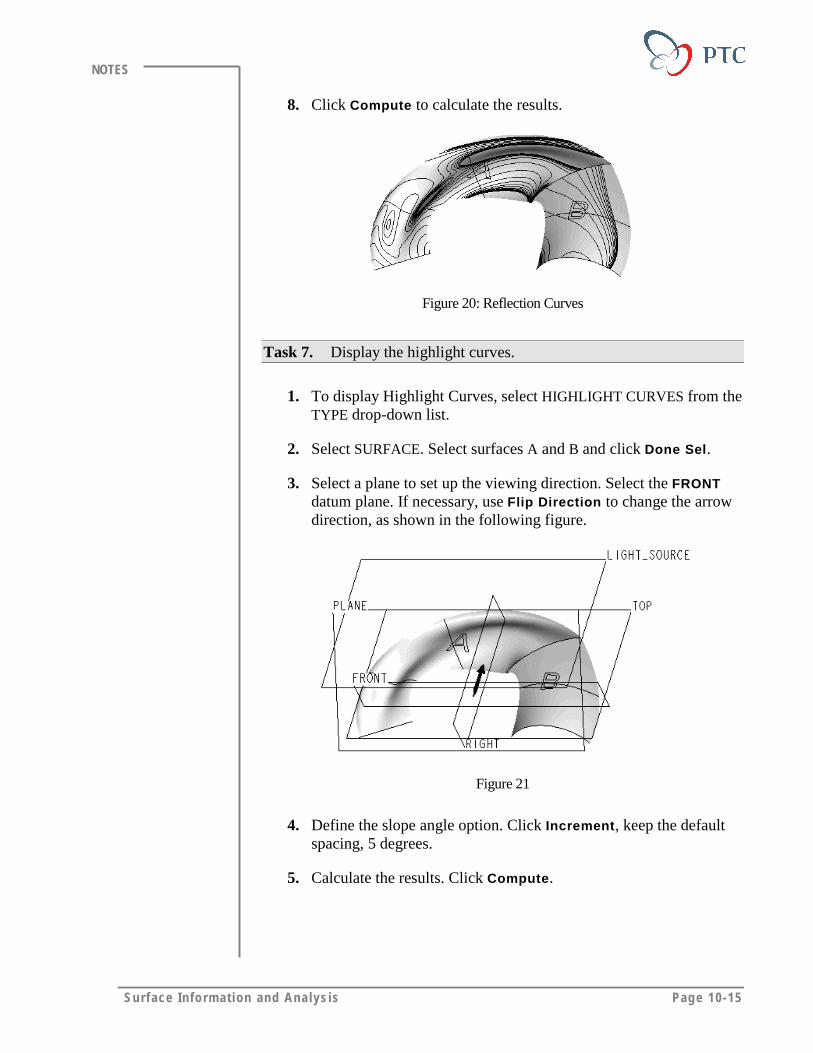
Surface Info rm at ion and Ana lys is Page 10-15
NOTES
8. Click Compute to calculate the results.
Figure 20: Reflection Curves
Task 7. Display the highlight curves.
1. To display Highlight Curves, select HIGHLIGHT CURVES from theTYPE drop-down list.
2. Select SURFACE. Select surfaces A and B and click Done Sel.
3. Select a plane to set up the viewing direction. Select the FRONTdatum plane. If necessary, use Flip Direction to change the arrowdirection, as shown in the following figure.
Figure 21
4. Define the slope angle option. Click Increment, keep the defaultspacing, 5 degrees.
5. Calculate the results. Click Compute.
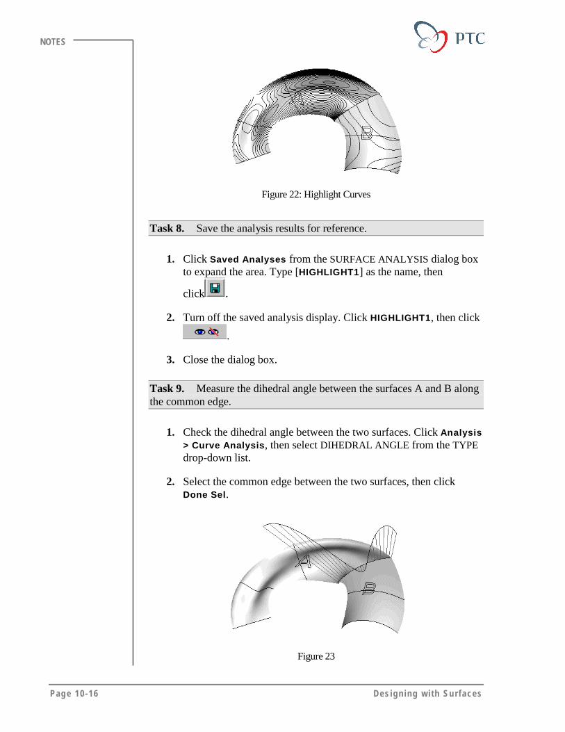
Page 10-16 Des igning w i th Surfaces
NOTES
Figure 22: Highlight Curves
Task 8. Save the analysis results for reference.
1. Click Saved Analyses from the SURFACE ANALYSIS dialog boxto expand the area. Type [HIGHLIGHT1] as the name, then
click .
2. Turn off the saved analysis display. Click HIGHLIGHT1, then click
.
3. Close the dialog box.
Task 9. Measure the dihedral angle between the surfaces A and B alongthe common edge.
1. Check the dihedral angle between the two surfaces. Click Analysis> Curve Analysis, then select DIHEDRAL ANGLE from the TYPEdrop-down list.
2. Select the common edge between the two surfaces, then clickDone Sel.
Figure 23
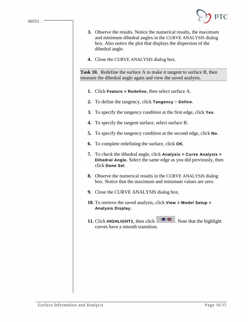
Surface Info rm at ion and Ana lys is Page 10-17
NOTES
3. Observe the results. Notice the numerical results, the maximumand minimum dihedral angles in the CURVE ANALYSIS dialogbox. Also notice the plot that displays the dispersion of thedihedral angle.
4. Close the CURVE ANALYSIS dialog box.
Task 10. Redefine the surface A to make it tangent to surface B, thenmeasure the dihedral angle again and view the saved analysis.
1. Click Feature > Redefine, then select surface A.
2. To define the tangency, click Tangency > Define.
3. To specify the tangency condition at the first edge, click Yes.
4. To specify the tangent surface, select surface B.
5. To specify the tangency condition at the second edge, click No.
6. To complete redefining the surface, click OK.
7. To check the dihedral angle, click Analysis > Curve Analysis >Dihedral Angle. Select the same edge as you did previously, thenclick Done Sel.
8. Observe the numerical results in the CURVE ANALYSIS dialogbox. Notice that the maximum and minimum values are zero.
9. Close the CURVE ANALYSIS dialog box.
10. To retrieve the saved analysis, click View > Model Setup >Analysis Display.
11. Click HIGHLIGHT1, then click . Note that the highlightcurves have a smooth transition.
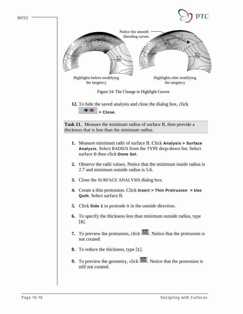
Page 10-18 Des igning w i th Surfaces
NOTES
Notice the smoothblending curves
Highlights before modifyingthe tangency
Highlights after modifyingthe tangency
Figure 24: The Change in Highlight Curves
12. To hide the saved analysis and close the dialog box, click
> Close.
Task 11. Measure the minimum radius of surface B, then provide athickness that is less than the minimum radius.
1. Measure minimum radii of surface B. Click Analysis > SurfaceAnalysis. Select RADIUS from the TYPE drop-down list. Selectsurface B then click Done Sel.
2. Observe the radii values. Notice that the minimum inside radius is2.7 and minimum outside radius is 5.6.
3. Close the SURFACE ANALYSIS dialog box.
4. Create a thin protrusion. Click Insert > Thin Protrusion > UseQuilt. Select surface B.
5. Click Side 1 to protrude it in the outside direction.
6. To specify the thickness less than minimum outside radius, type[5].
7. To preview the protrusion, click . Notice that the protrusion isnot created.
8. To reduce the thickness, type [1].
9. To preview the geometry, click . Notice that the protrusion isstill not created.

Surface Info rm at ion and Ana lys is Page 10-19
NOTES
10. Click to cancel the feature creation. To confirm the action,click Yes.
Task 12. To understand the reason of protrusion failure, carry out adetailed surface analysis.
1. To display the Gaussian curvature of surface B, click Analysis >Surface Analysis. Select GAUSS CURVATURE from the TYPEdrop-down list.
2. Select the SURFACE. Select surface B, then click Done Sel.
3. To modify the settings, click Computation Settings in SURFACEANALYSIS dialog box to expand it. Click Dynamic Update.
4. To modify the quality, click (if necessary) then drag theslider to somewhere in the center of the bar length.
Sharp change in thecurvature
Figure 25
5. Observe the results. Notice the sharp change in curvature isdisplayed in the middle of the surface.
Task 13. Analyze surface B further using porcupines.
1. Select PORCUPINE from the TYPE drop-down list.
2. Select the surface B, then click Done Sel.
3. To modify the display, click Display, then click Dynamic Update.Rotate the buttons to reduce the height of the display.
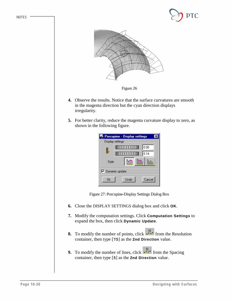
Page 10-20 Des igning w i th Surfaces
NOTES
Figure 26
4. Observe the results. Notice that the surface curvatures are smoothin the magenta direction but the cyan direction displaysirregularity.
5. For better clarity, reduce the magenta curvature display to zero, asshown in the following figure.
Figure 27: Porcupine-Display Settings Dialog Box
6. Close the DISPLAY SETTINGS dialog box and click OK.
7. Modify the computation settings. Click Computation Settings toexpand the box, then click Dynamic Update.
8. To modify the number of points, click from the Resolutioncontainer, then type [75] as the 2nd Direction value.
9. To modify the number of lines, click from the Spacingcontainer, then type [5] as the 2nd Direction value.
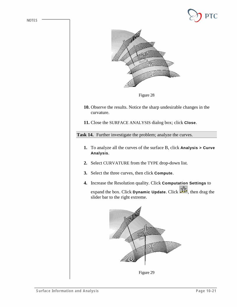
Surface Info rm at ion and Ana lys is Page 10-21
NOTES
Figure 28
10. Observe the results. Notice the sharp undesirable changes in thecurvature.
11. Close the SURFACE ANALYSIS dialog box; click Close.
Task 14. Further investigate the problem; analyze the curves.
1. To analyze all the curves of the surface B, click Analysis > CurveAnalysis.
2. Select CURVATURE from the TYPE drop-down list.
3. Select the three curves, then click Compute.
4. Increase the Resolution quality. Click Computation Settings to
expand the box. Click Dynamic Update. Click , then drag theslider bar to the right extreme.
Figure 29
Page 10-22 Des igning w i th Surfaces
NOTES
5. Observe the results. Notice that the second and the third curves areimproper and have very sharp change in curvature.
6. Close the CURVE ANALYSIS dialog box; click Close.
7. Erase the model from the memory.
Note
You can redefine and modify the curves to improve the surfacequality, but for the scope of this module, you can end theexercise here.
Surface Info rm at ion and Ana lys is Page 10-23
NOTES
MODULE SUMMARYIn this module, you have learned that:
• You can use a combination of surface or curve analysis tools to get thedesired feedback.
• Surface tangency can be visualized using many tools like Gaussiancurvature, Section Curvature, Porcupines, Highlight Curves etc.
• Gaussian Curvature and Porcupines are particularly useful indetermining curvature continuity.
• You can use Dihedral Angle to obtain mathematical feedback abouttangency of two surfaces.
• You can use Reflection Curves to determine the aesthetic quality of asurface.

Page 11-1
Module
Surface ContinuitiesIn this module you learn to create curvature continuous surfaces.
Objectives
After completing this module, you will be able to:
• Define fundamentals of curvature.
• Define the possible surface continuities.
• Define and create curvature continuous surfaces.

Page 11-2 Des igning w i th Surfaces
NOTES
THE CURVATUREA curvature is defined as a portion of a surface that is proportional to 1/r atany given point on a curve. The smaller the radius value, the greater thecurvature will be. To detect changes in curvature, you can use acombination of surface information tools available with Pro/ENGINEER.
Figure 1: Varying Curvature of a Spline
When designing surfaces with curvature, keep in mind the following:
• A straight line has a zero curvature since 1/∞ = zero.
• A true arc has constant curvature at all points along the curve, basedon its radius.
• Splines, in general, have constantly changing curvature.
• Geometry can contain inflection points, where the curvature switchesfrom one side of the surface to the other.

Surface Cont inui t ies Page 11-3
NOTES
CONTINUITY BETWEEN GEOMETRIC ENTITIESWhen geometry is joined at a common boundary, the surfaces can meet atthree different levels of continuity:
• G0 – The geometry shares a common boundary. It is discontinuous inboth tangency (slope) and curvature continuity (change in slope).
Figure 2: G0 Continuity
• G1 (Tangent Continuous) – The geometry is both joined and tangent(continuous in slope), as well as discontinuous in curvature.
Figure 3: G1 Continuity
• G2 (Curvature Continuous) – The geometry is joined, tangent, andcontinuous in curvature.
Figure 4: Curvature Continuity

Page 11-4 Des igning w i th Surfaces
NOTES
USING CURVATURE CONTINUOUS SURFACESTo attain a higher degree of smoothness between the surface patches, youdefine the continuity as curvature continuous (G2). You can create G2surfaces for aesthetic or engineering design such as:
• Exterior panels of products, for example: automobiles with shiny andglossy surface finishes that are painted, chrome-plated, or glass (ClassA surfaces).
• Products that require smooth surfaces to improve fluid-dynamic (oraerodynamic) properties, for example: valves and flow meters.
Creating Curvature Continuous SurfacesCreating curvature continuous surfaces in a given model is dependent onthe existing features that are referenced to create the surfaces. There arelimitations to consider when creating curvature continuous surfaces.
Limitations in Creating Curvature Continuous Surfaces
• To create the curvature continuous surfaces, the references, such ascurves or edges, must have curvature continuity.
• A boundary surface can only be curvature continuous in one direction,as shown in the following figure.
Tangent in the First Direction
Tangent in theFirst Direction
CurvatureContinuous in theSecond Direction
Curvature Continuous inthe Second Direction
Figure 5: Curvature Continuous Boundary Condition
• A surface created between existing curves (edges) in two directionscan not be defined to have a boundary condition of tangent orcurvature continuous, unless all the referenced curves are tangent orcurvature continuous with the adjoining surfaces.
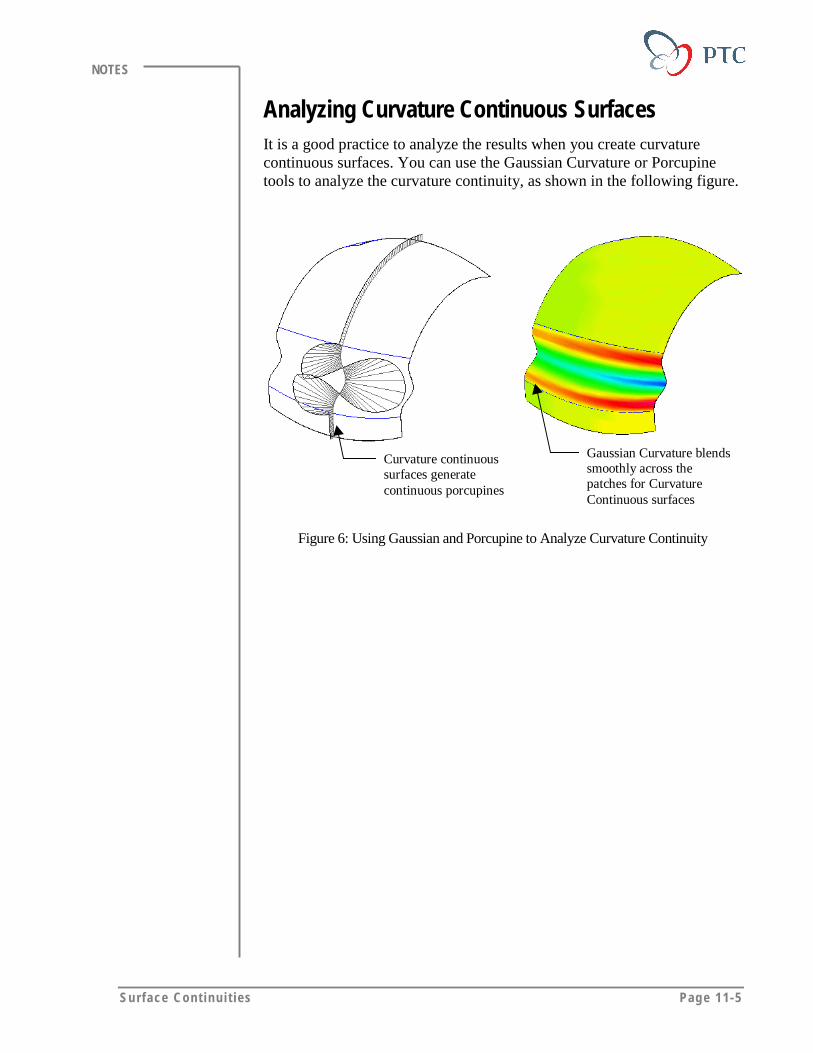
Surface Cont inui t ies Page 11-5
NOTES
Analyzing Curvature Continuous SurfacesIt is a good practice to analyze the results when you create curvaturecontinuous surfaces. You can use the Gaussian Curvature or Porcupinetools to analyze the curvature continuity, as shown in the following figure.
Curvature continuoussurfaces generatecontinuous porcupines
Gaussian Curvature blendssmoothly across thepatches for CurvatureContinuous surfaces
Figure 6: Using Gaussian and Porcupine to Analyze Curvature Continuity

Page 11-6 Des igning w i th Surfaces
NOTES
LABORATORY PRACTICALGoal
In this laboratory, you create and analyze curvature continuous blended
transitions between the surfaces.
Method
In this exercise you finish the shape of a mouse by creating blendedtransitions. You create the transitions so that they are curvature continuouswith the adjacent surfaces.
ToolsIcon Description
Done
Repaint the screen
Make selected layers shown
Create an offset entity from an edge
Impose Sketcher constraints
Create same points or collinear constraint
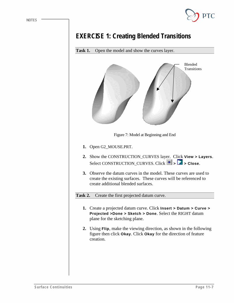
Surface Cont inui t ies Page 11-7
NOTES
EXERCISE 1: Creating Blended Transitions
Task 1. Open the model and show the curves layer.
BlendedTransitions
Figure 7: Model at Beginning and End
1. Open G2_MOUSE.PRT.
2. Show the CONSTRUCTION_CURVES layer. Click View > Layers.
Select CONSTRUCTION_CURVES. Click > > Close.
3. Observe the datum curves in the model. These curves are used tocreate the existing surfaces. These curves will be referenced tocreate additional blended surfaces.
Task 2. Create the first projected datum curve.
1. Create a projected datum curve. Click Insert > Datum > Curve >Projected >Done > Sketch > Done. Select the RIGHT datumplane for the sketching plane.
2. Using Flip, make the viewing direction, as shown in the followingfigure then click Okay. Click Okay for the direction of featurecreation.
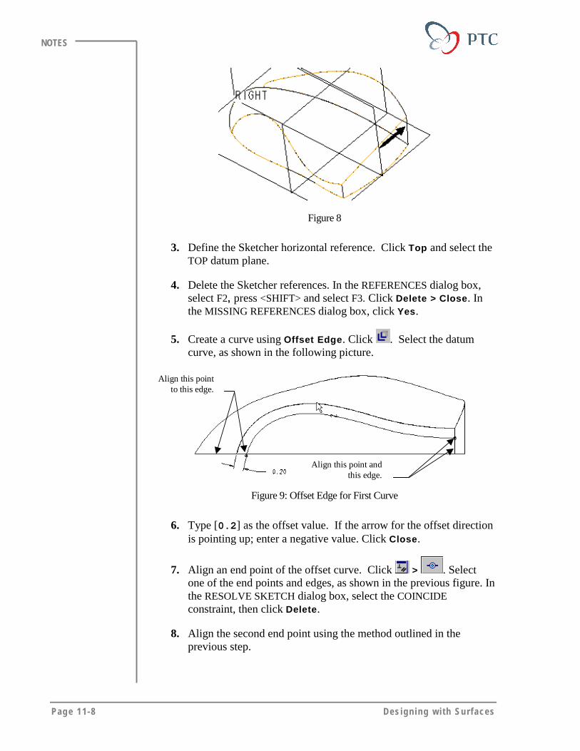
Page 11-8 Des igning w i th Surfaces
NOTES
Figure 8
3. Define the Sketcher horizontal reference. Click Top and select theTOP datum plane.
4. Delete the Sketcher references. In the REFERENCES dialog box,select F2, press <SHIFT> and select F3. Click Delete > Close. Inthe MISSING REFERENCES dialog box, click Yes.
5. Create a curve using Offset Edge. Click . Select the datumcurve, as shown in the following picture.
Align this point andthis edge.
Align this pointto this edge.
Figure 9: Offset Edge for First Curve
6. Type [0.2] as the offset value. If the arrow for the offset directionis pointing up; enter a negative value. Click Close.
7. Align an end point of the offset curve. Click > . Selectone of the end points and edges, as shown in the previous figure. Inthe RESOLVE SKETCH dialog box, select the COINCIDEconstraint, then click Delete.
8. Align the second end point using the method outlined in theprevious step.
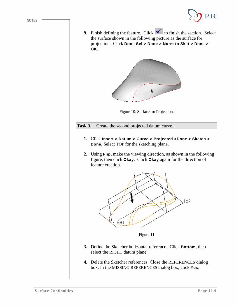
Surface Cont inui t ies Page 11-9
NOTES
9. Finish defining the feature. Click to finish the section. Selectthe surface shown in the following picture as the surface forprojection. Click Done Sel > Done > Norm to Sket > Done >OK.
Figure 10: Surface for Projection.
Task 3. Create the second projected datum curve.
1. Click Insert > Datum > Curve > Projected >Done > Sketch >Done. Select TOP for the sketching plane.
2. Using Flip, make the viewing direction, as shown in the followingfigure, then click Okay. Click Okay again for the direction offeature creation.
Figure 11
3. Define the Sketcher horizontal reference. Click Bottom, thenselect the RIGHT datum plane.
4. Delete the Sketcher references. Close the REFERENCES dialogbox. In the MISSING REFERENCES dialog box, click Yes.
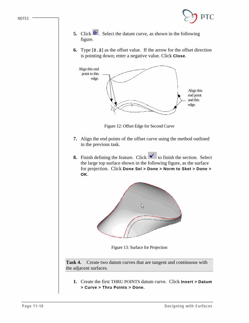
Page 11-10 Des igning w i th Surfaces
NOTES
5. Click . Select the datum curve, as shown in the followingfigure.
6. Type [0.2] as the offset value. If the arrow for the offset directionis pointing down; enter a negative value. Click Close.
Align this endpoint to this
edge.
Align thisend pointand thisedge.
Figure 12: Offset Edge for Second Curve
7. Align the end points of the offset curve using the method outlinedin the previous task.
8. Finish defining the feature. Click to finish the section. Selectthe large top surface shown in the following figure, as the surfacefor projection. Click Done Sel > Done > Norm to Sket > Done >OK.
Figure 13: Surface for Projection
Task 4. Create two datum curves that are tangent and continuous withthe adjacent surfaces.
1. Create the first THRU POINTS datum curve. Click Insert > Datum> Curve > Thru Points > Done.
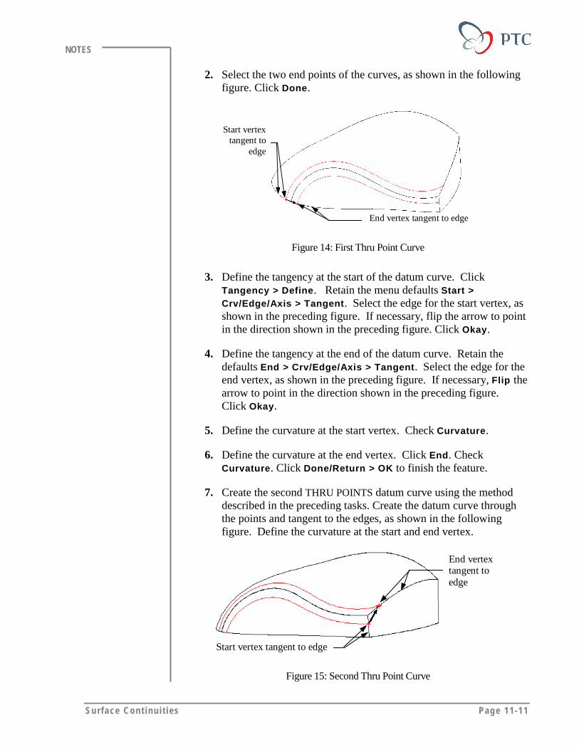
Surface Cont inui t ies Page 11-11
NOTES
2. Select the two end points of the curves, as shown in the followingfigure. Click Done.
End vertex tangent to edge
Start vertextangent to
edge
Figure 14: First Thru Point Curve
3. Define the tangency at the start of the datum curve. ClickTangency > Define. Retain the menu defaults Start >Crv/Edge/Axis > Tangent. Select the edge for the start vertex, asshown in the preceding figure. If necessary, flip the arrow to pointin the direction shown in the preceding figure. Click Okay.
4. Define the tangency at the end of the datum curve. Retain thedefaults End > Crv/Edge/Axis > Tangent. Select the edge for theend vertex, as shown in the preceding figure. If necessary, Flip thearrow to point in the direction shown in the preceding figure.Click Okay.
5. Define the curvature at the start vertex. Check Curvature.
6. Define the curvature at the end vertex. Click End. CheckCurvature. Click Done/Return > OK to finish the feature.
7. Create the second THRU POINTS datum curve using the methoddescribed in the preceding tasks. Create the datum curve throughthe points and tangent to the edges, as shown in the followingfigure. Define the curvature at the start and end vertex.
Start vertex tangent to edge
End vertextangent toedge
Figure 15: Second Thru Point Curve

Page 11-12 Des igning w i th Surfaces
NOTES
Task 5. Create a blended surface with continuous boundaries.
1. Click Insert > Surface > From Boundaries > Blended Surf >Done. Keep the defaults and select only the curves for theboundaries in the first direction, as shown in the following figure.
First Direction Curve 1First Direction Curve 2
SecondDirection
Curve 1 Second Direction Curve 2
Figure 16: Blended Surface
2. Define the curves in the second direction. Click Second Dir, thenselect the curves shown in the preceding figure. Click DoneCurves.
3. Define the boundary conditions. Click Bndry Conds > Define >Boundary # 1 > Crvtr Cont > Done > OK. Click Boundary #2 >Crvtr Cont > Done > OK.
4. Finish the feature. Click Done > OK.
Figure 17
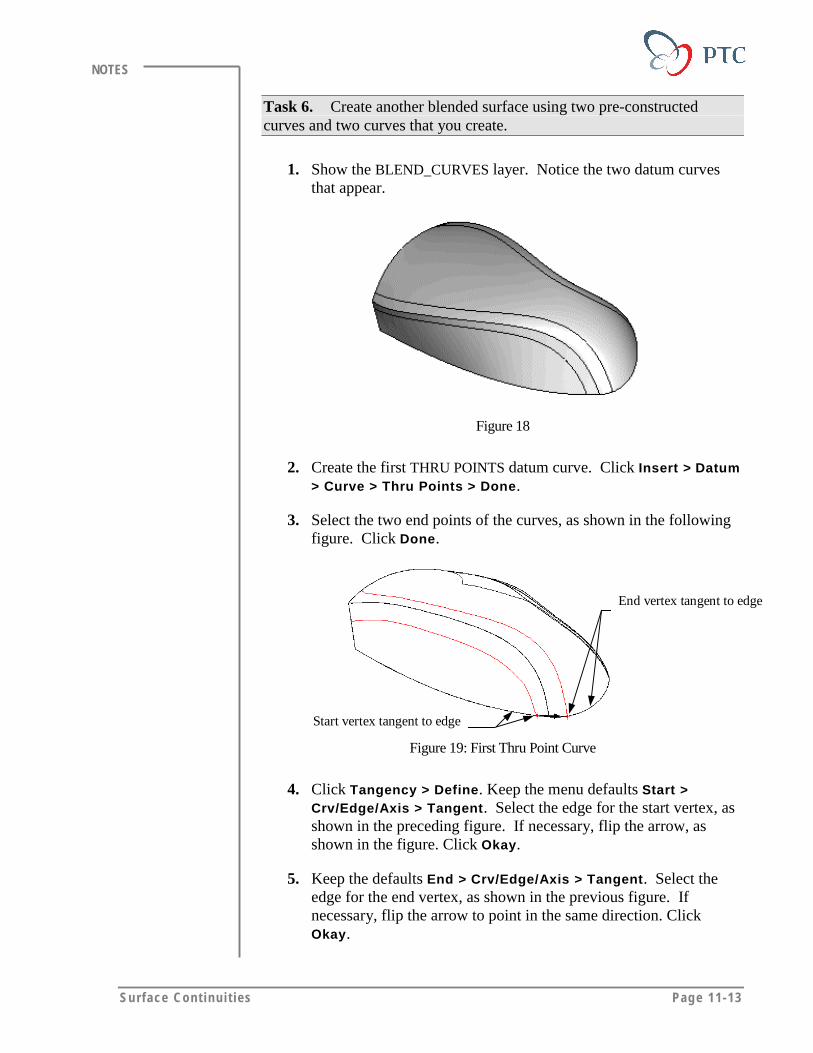
Surface Cont inui t ies Page 11-13
NOTES
Task 6. Create another blended surface using two pre-constructedcurves and two curves that you create.
1. Show the BLEND_CURVES layer. Notice the two datum curvesthat appear.
Figure 18
2. Create the first THRU POINTS datum curve. Click Insert > Datum> Curve > Thru Points > Done.
3. Select the two end points of the curves, as shown in the followingfigure. Click Done.
Start vertex tangent to edge
End vertex tangent to edge
Figure 19: First Thru Point Curve
4. Click Tangency > Define. Keep the menu defaults Start >Crv/Edge/Axis > Tangent. Select the edge for the start vertex, asshown in the preceding figure. If necessary, flip the arrow, asshown in the figure. Click Okay.
5. Keep the defaults End > Crv/Edge/Axis > Tangent. Select theedge for the end vertex, as shown in the previous figure. Ifnecessary, flip the arrow to point in the same direction. ClickOkay.
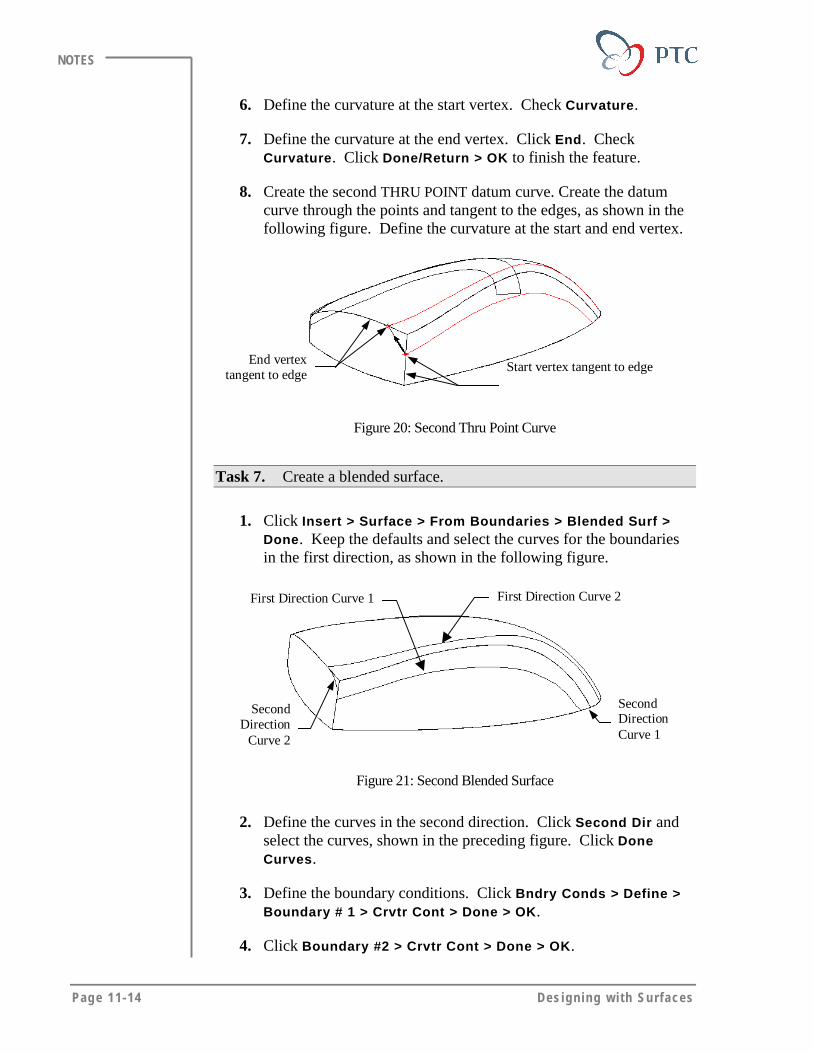
Page 11-14 Des igning w i th Surfaces
NOTES
6. Define the curvature at the start vertex. Check Curvature.
7. Define the curvature at the end vertex. Click End. CheckCurvature. Click Done/Return > OK to finish the feature.
8. Create the second THRU POINT datum curve. Create the datumcurve through the points and tangent to the edges, as shown in thefollowing figure. Define the curvature at the start and end vertex.
End vertextangent to edge
Start vertex tangent to edge
Figure 20: Second Thru Point Curve
Task 7. Create a blended surface.
1. Click Insert > Surface > From Boundaries > Blended Surf >Done. Keep the defaults and select the curves for the boundariesin the first direction, as shown in the following figure.
First Direction Curve 1 First Direction Curve 2
SecondDirectionCurve 1
SecondDirection
Curve 2
Figure 21: Second Blended Surface
2. Define the curves in the second direction. Click Second Dir andselect the curves, shown in the preceding figure. Click DoneCurves.
3. Define the boundary conditions. Click Bndry Conds > Define >Boundary # 1 > Crvtr Cont > Done > OK.
4. Click Boundary #2 > Crvtr Cont > Done > OK.
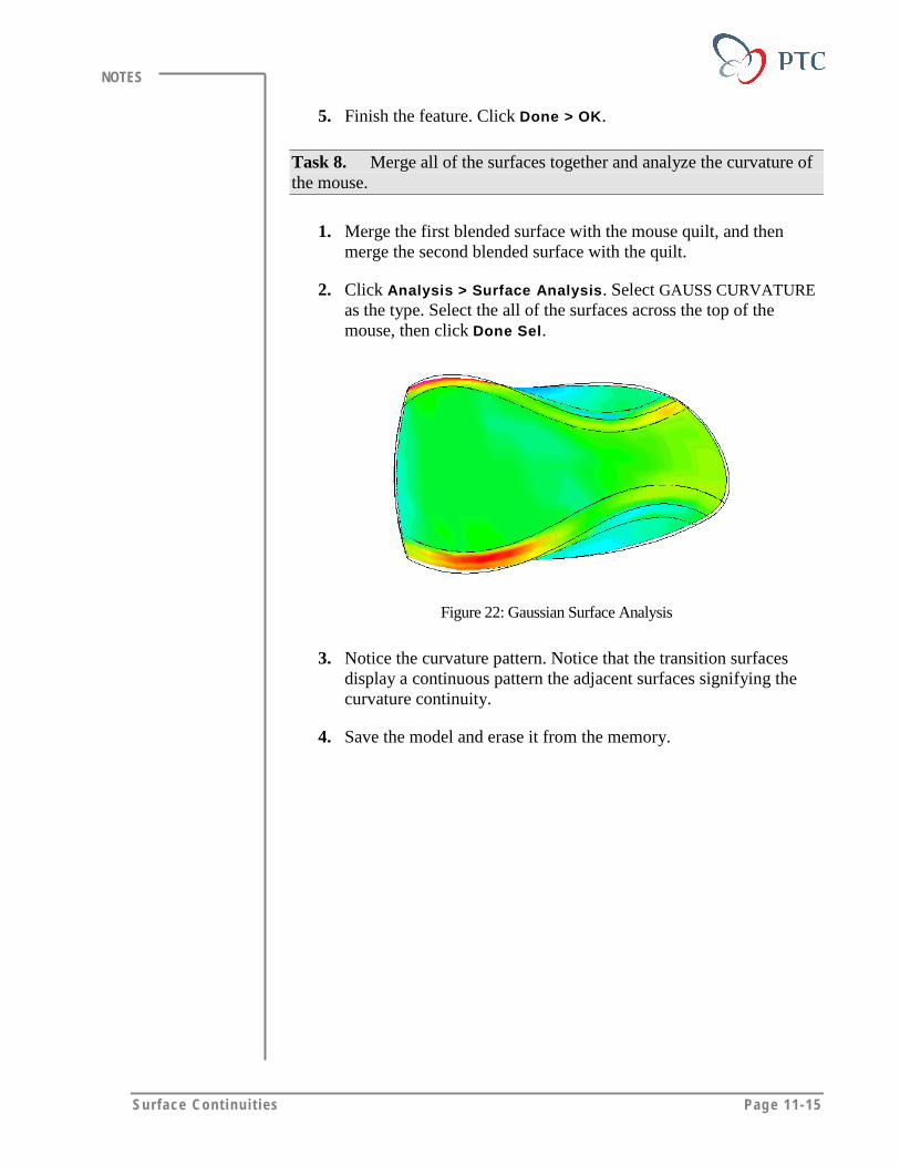
Surface Cont inui t ies Page 11-15
NOTES
5. Finish the feature. Click Done > OK.
Task 8. Merge all of the surfaces together and analyze the curvature ofthe mouse.
1. Merge the first blended surface with the mouse quilt, and thenmerge the second blended surface with the quilt.
2. Click Analysis > Surface Analysis. Select GAUSS CURVATUREas the type. Select the all of the surfaces across the top of themouse, then click Done Sel.
Figure 22: Gaussian Surface Analysis
3. Notice the curvature pattern. Notice that the transition surfacesdisplay a continuous pattern the adjacent surfaces signifying thecurvature continuity.
4. Save the model and erase it from the memory.
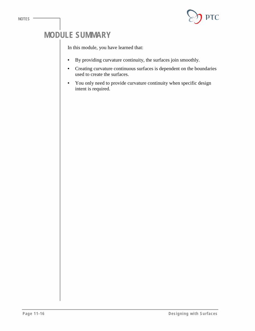
Page 11-16 Des igning w i th Surfaces
NOTES
MODULE SUMMARYIn this module, you have learned that:
• By providing curvature continuity, the surfaces join smoothly.
• Creating curvature continuous surfaces is dependent on the boundariesused to create the surfaces.
• You only need to provide curvature continuity when specific designintent is required.

Page 12-1
Module
Additional Advanced Surfacing ToolsIn this module you learn how to use additional advanced surfacing
tools.
Objectives
After completing this module, you will be able to:
• Define additional advanced surfacing options.
• Create a draft surface using the Tangent-to-Surface option.
• Create free form features.

Page 12-2 Des igning w i th Surfaces
NOTES
USING ADDITIONAL SURFACING OPTIONSThe following advance surfacing options enable you to capture specificdesign intents such as:
• Section to Surface
• Surface to Surface
• Tangent to Surface
• Free Form
SECTION TO SURFACEThe Section to Surface option enables you to create a transitional surfacebetween a set of tangent surfaces and a sketched contour. To use theSection to Surface option:
• The set of surfaces selected for the tangent boundary must be closed.
• The sketched section or the selected edges must be closed.
Step 1 Step 2
Step 3 Step 4
Tangent Surface
Section
Figure 1: Using the Section-To-Surface Option
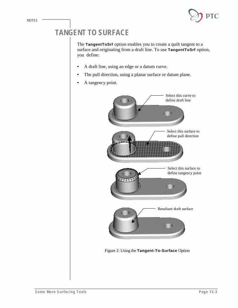
Some More Surfac ing Too ls Page 12-3
NOTES
TANGENT TO SURFACEThe TangentToSrf option enables you to create a quilt tangent to asurface and originating from a draft line. To use TangentToSrf option,you define:
• A draft line, using an edge or a datum curve.
• The pull direction, using a planar surface or datum plane.
• A tangency point.
Select this curve todefine draft line
Select this surface todefine pull direction
Select this surface todefine tangency point
Resultant draft surface
Figure 2: Using the Tangent-To-Surface Option
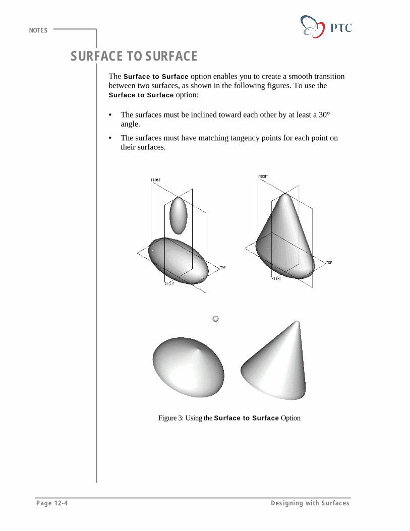
Page 12-4 Des igning w i th Surfaces
NOTES
SURFACE TO SURFACEThe Surface to Surface option enables you to create a smooth transitionbetween two surfaces, as shown in the following figures. To use theSurface to Surface option:
• The surfaces must be inclined toward each other by at least a 30°angle.
• The surfaces must have matching tangency points for each point ontheir surfaces.
Figure 3: Using the Surface to Surface Option
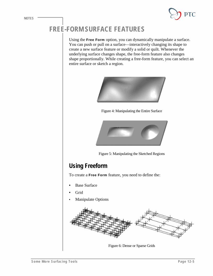
Some More Surfac ing Too ls Page 12-5
NOTES
FREE-FORM SURFACE FEATURESUsing the Free Form option, you can dynamically manipulate a surface.You can push or pull on a surface—interactively changing its shape tocreate a new surface feature or modify a solid or quilt. Whenever theunderlying surface changes shape, the free-form feature also changesshape proportionally. While creating a free-form feature, you can select anentire surface or sketch a region.
Figure 4: Manipulating the Entire Surface
Figure 5: Manipulating the Sketched Regions
Using FreeformTo create a Free Form feature, you need to define the:
• Base Surface
• Grid
• Manipulate Options
Figure 6: Dense or Sparse Grids
Page 12-6 Des igning w i th Surfaces
NOTES
Defining Manipulate OptionsThe Manipulate option in the Free Form dialog box, enables you to dragthe control points in order to manipulate the shape of the surface. You cancontrol the movement of the points by defining the following options inthe MODIFY SURFACE dialog box:
Movement Plane
You can drag the points with reference to one of the following planes:
• Dynamic Plane – The movement plane is a tangent plane that passesthrough the selected point. The dynamic movement plane follows theselected point.
• Defined Plane – Select a datum plane to be the movement plane.
• Original Plane – The movement plane is a tangent plane that passesthrough the original location of the selected point.
Movement Direction
You can specify the following directions for the point movement:
• First
• Second
• Normal
Region
While moving the points you can define the Poly Motion region usingfollowing options:
• Smooth
• Linear
• Constant
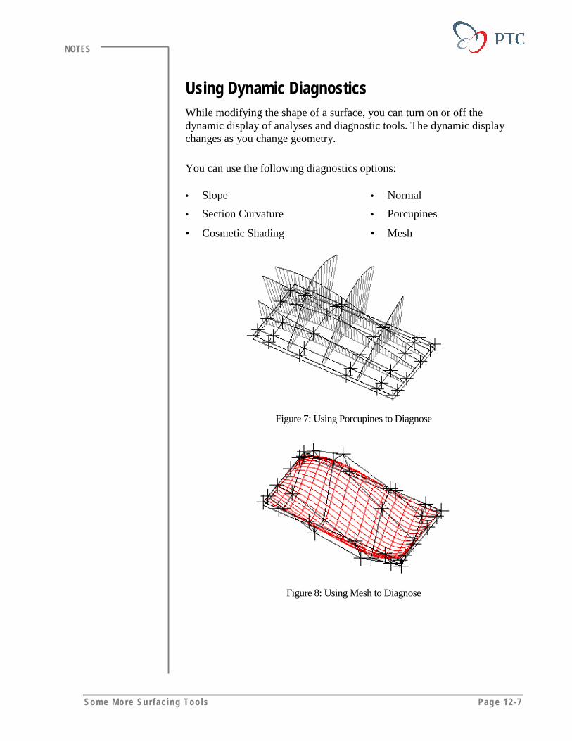
Some More Surfac ing Too ls Page 12-7
NOTES
Using Dynamic DiagnosticsWhile modifying the shape of a surface, you can turn on or off thedynamic display of analyses and diagnostic tools. The dynamic displaychanges as you change geometry.
You can use the following diagnostics options:
• Slope
• Section Curvature
• Cosmetic Shading
• Normal
• Porcupines
• Mesh
Figure 7: Using Porcupines to Diagnose
Figure 8: Using Mesh to Diagnose
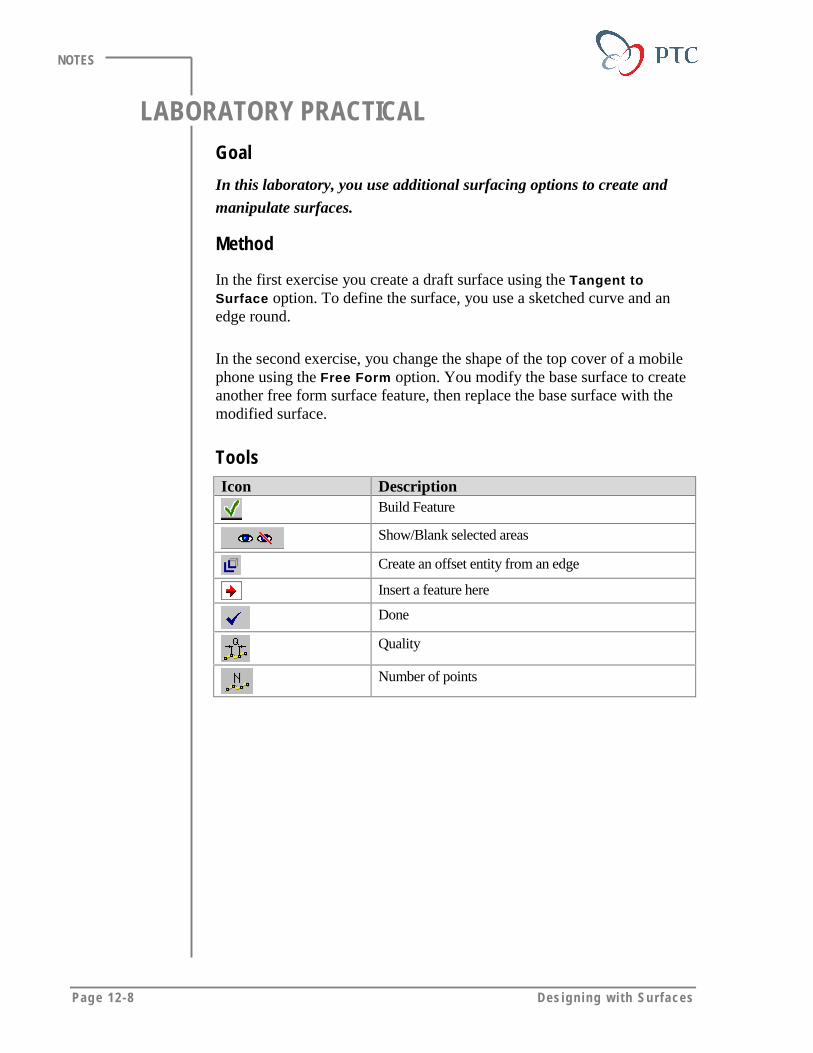
Page 12-8 Des igning w i th Surfaces
NOTES
LABORATORY PRACTICALGoal
In this laboratory, you use additional surfacing options to create and
manipulate surfaces.
Method
In the first exercise you create a draft surface using the Tangent toSurface option. To define the surface, you use a sketched curve and anedge round.
In the second exercise, you change the shape of the top cover of a mobilephone using the Free Form option. You modify the base surface to createanother free form surface feature, then replace the base surface with themodified surface.
ToolsIcon Description
Build Feature
Show/Blank selected areas
Create an offset entity from an edge
Insert a feature here
Done
Quality
Number of points

Some More Surfac ing Too ls Page 12-9
NOTES
EXERCISE 1: Creating Draft Surfaces of a Boss
Task 1. Open model and observe the features.
1. Open DRAFT.PRT.
RibBoss
Figure 9: The Flange Part
2. Observe the model. A rib has already been added to the boss andpatterned rotationally. Notice that the ribs and the boss havealready been rounded.
3. Observe the Model Tree. Expand the pattern in the Model Tree.Expand the first group in the pattern. The first rib was created andthen a round was applied to the edges of the rib. These twofeatures were then grouped together and patterned.
Task 2. Attempt to draft the boss and ribs.
1. To create a draft for the boss and ribs, click Insert > Draft >Neutral Pln > Done > Tweak > No Split > Constant > Done.
2. To select the draft surfaces, click Loop Surfs. Select the surface,and then select the edge, as shown in the following figure. ClickDone.
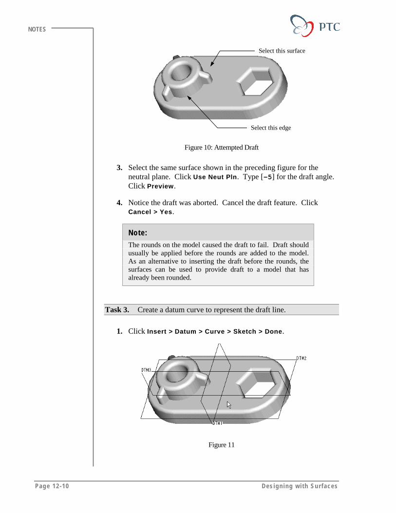
Page 12-10 Des igning w i th Surfaces
NOTES
Select this surface
Select this edge
Figure 10: Attempted Draft
3. Select the same surface shown in the preceding figure for theneutral plane. Click Use Neut Pln. Type [–5] for the draft angle.Click Preview.
4. Notice the draft was aborted. Cancel the draft feature. ClickCancel > Yes.
Note:
The rounds on the model caused the draft to fail. Draft shouldusually be applied before the rounds are added to the model.As an alternative to inserting the draft before the rounds, thesurfaces can be used to provide draft to a model that hasalready been rounded.
Task 3. Create a datum curve to represent the draft line.
1. Click Insert > Datum > Curve > Sketch > Done.
Figure 11

Some More Surfac ing Too ls Page 12-11
NOTES
2. Select the surface shown in the preceding figure for the sketchplane. Click Okay > Bottom. Select DTM3 as the reference plane.
3. Delete the references from the REFERENCES dialog box.
4. Click > Yes. Click Loop and select the surface shown in theprevious figure. Click Next until the edges of the boss arehighlighted. Click Accept and type [2] as the offset distance.
5. Sketch a circle on top of the offset entities, as shown in followingfigure.
Sketch a circle here.
Figure 12: Sketching a Datum Curve
6. Finish the curve. Click > OK.
Task 4. Create a draft on the boss and ribs using surface features.
1. To create a surface, click Insert > Surface > Blend Tangent ToSurfaces.
2. Click One By One > Query Sel. Select the circle. Toggle throughthe QUERY BIN until only the circle is highlighted. Click Accept> Done Sel > Done.
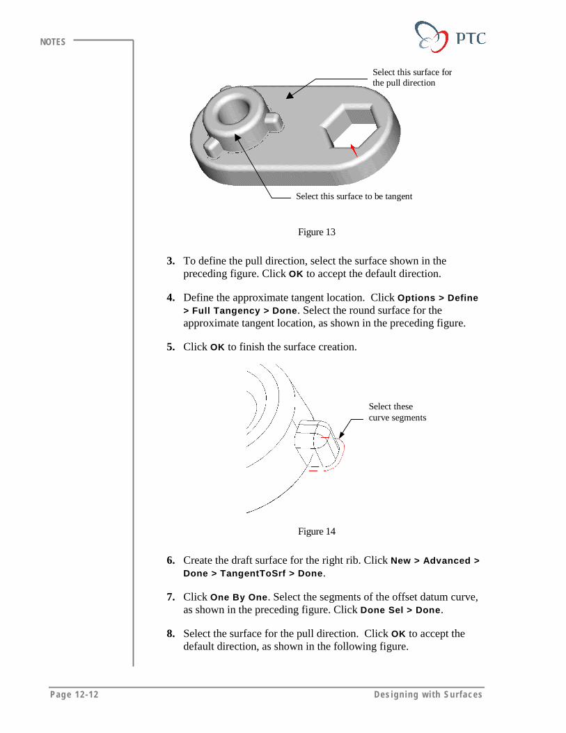
Page 12-12 Des igning w i th Surfaces
NOTES
Select this surface forthe pull direction
Select this surface to be tangent
Figure 13
3. To define the pull direction, select the surface shown in thepreceding figure. Click OK to accept the default direction.
4. Define the approximate tangent location. Click Options > Define> Full Tangency > Done. Select the round surface for theapproximate tangent location, as shown in the preceding figure.
5. Click OK to finish the surface creation.
Select thesecurve segments
Figure 14
6. Create the draft surface for the right rib. Click New > Advanced >Done > TangentToSrf > Done.
7. Click One By One. Select the segments of the offset datum curve,as shown in the preceding figure. Click Done Sel > Done.
8. Select the surface for the pull direction. Click OK to accept thedefault direction, as shown in the following figure.
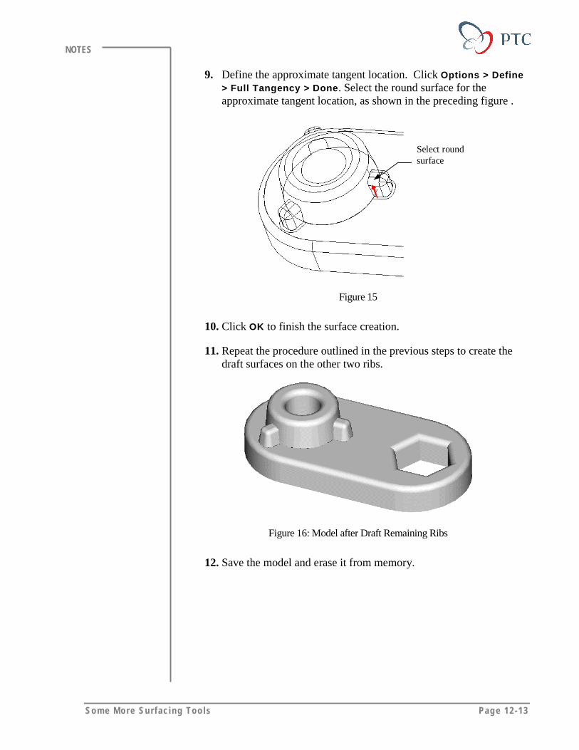
Some More Surfac ing Too ls Page 12-13
NOTES
9. Define the approximate tangent location. Click Options > Define> Full Tangency > Done. Select the round surface for theapproximate tangent location, as shown in the preceding figure .
Select roundsurface
Figure 15
10. Click OK to finish the surface creation.
11. Repeat the procedure outlined in the previous steps to create thedraft surfaces on the other two ribs.
Figure 16: Model after Draft Remaining Ribs
12. Save the model and erase it from memory.

Page 12-14 Des igning w i th Surfaces
NOTES
EXERCISE 2: Free Form Manipulation
Task 1. Open the model. Create a freeform feature and start tomanipulate the shape.
1. Open PHONE_TOP_COVER.PRT.
Figure 17: The Original Shape
2. In the Model Tree, drag [Insert Here] between PROTRUSION ID2062 and CURVE ID 297 in the Model Tree.
Figure 18: Protrusion Feature
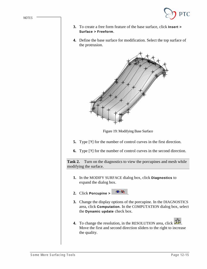
Some More Surfac ing Too ls Page 12-15
NOTES
3. To create a free form feature of the base surface, click Insert >Surface > Freeform.
4. Define the base surface for modification. Select the top surface ofthe protrusion.
Figure 19: Modifying Base Surface
5. Type [7] for the number of control curves in the first direction.
6. Type [7] for the number of control curves in the second direction.
Task 2. Turn on the diagnostics to view the porcupines and mesh whilemodifying the surface.
1. In the MODIFY SURFACE dialog box, click Diagnostics toexpand the dialog box.
2. Click Porcupine > .
3. Change the display options of the porcupine. In the DIAGNOSTICSarea, click Computation. In the COMPUTATION dialog box, selectthe Dynamic update check box.
4. To change the resolution, in the RESOLUTION area, click .Move the first and second direction sliders to the right to increasethe quality.
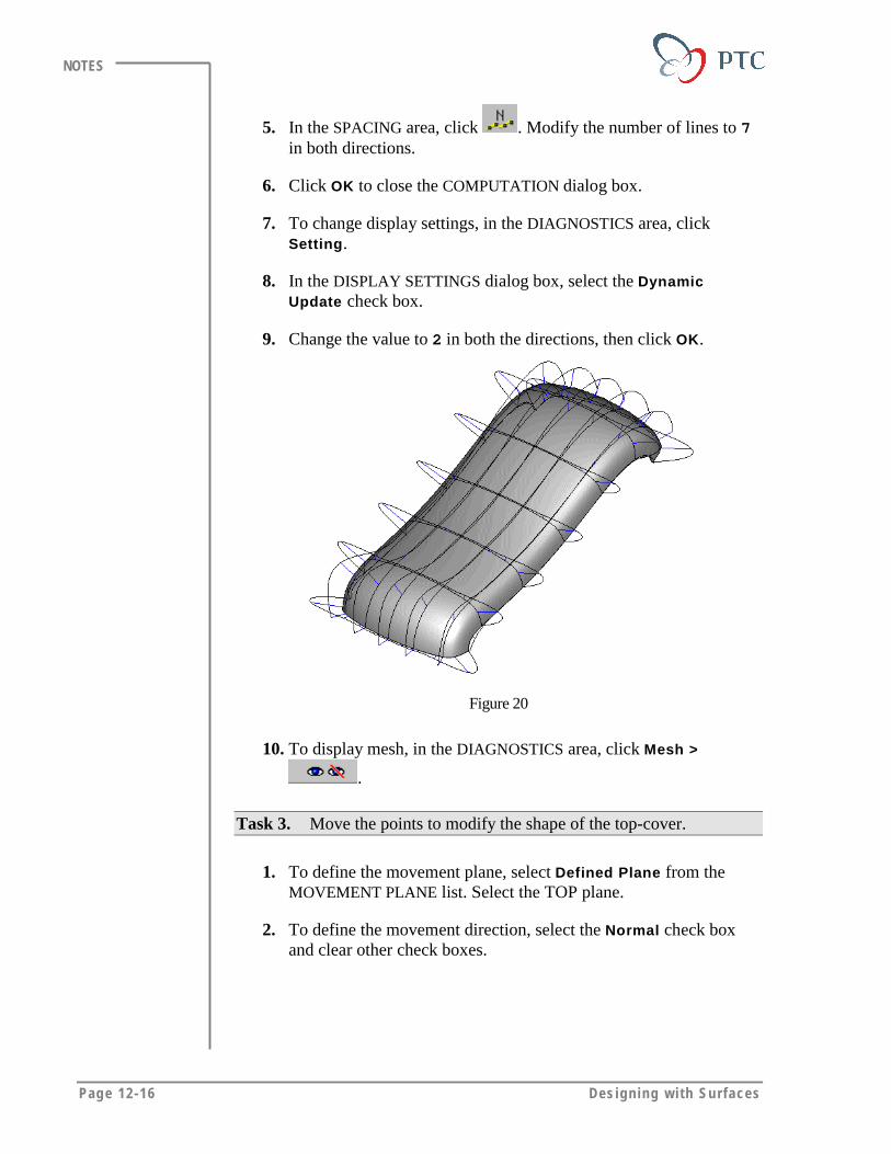
Page 12-16 Des igning w i th Surfaces
NOTES
5. In the SPACING area, click . Modify the number of lines to 7in both directions.
6. Click OK to close the COMPUTATION dialog box.
7. To change display settings, in the DIAGNOSTICS area, clickSetting.
8. In the DISPLAY SETTINGS dialog box, select the DynamicUpdate check box.
9. Change the value to 2 in both the directions, then click OK.
Figure 20
10. To display mesh, in the DIAGNOSTICS area, click Mesh >
.
Task 3. Move the points to modify the shape of the top-cover.
1. To define the movement plane, select Defined Plane from theMOVEMENT PLANE list. Select the TOP plane.
2. To define the movement direction, select the Normal check boxand clear other check boxes.

Some More Surfac ing Too ls Page 12-17
NOTES
Raise the points aroundthis zone
Lower the points around this zone
Figure 21: Modifying Shape
3. Drag the points in order to modify the shape of the model. Depressthe surface slightly in the keypad area and raise the surface arounddisplay area, as shown in the preceding figure. Use porcupines tocontrol the change in the shape. If necessary, rotate the modelwhile modifying the shape.
4. To finish modifying the free form feature, click > OK.
Figure 22: Final Shape
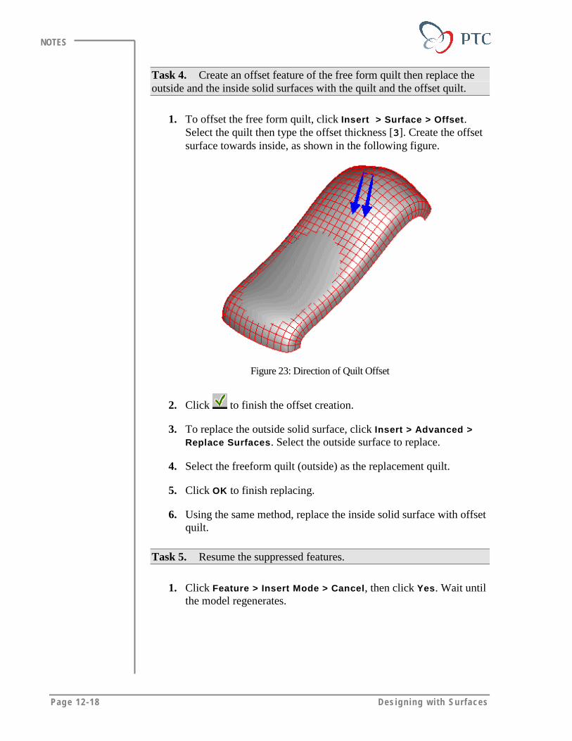
Page 12-18 Des igning w i th Surfaces
NOTES
Task 4. Create an offset feature of the free form quilt then replace theoutside and the inside solid surfaces with the quilt and the offset quilt.
1. To offset the free form quilt, click Insert > Surface > Offset.Select the quilt then type the offset thickness [3]. Create the offsetsurface towards inside, as shown in the following figure.
Figure 23: Direction of Quilt Offset
2. Click to finish the offset creation.
3. To replace the outside solid surface, click Insert > Advanced >Replace Surfaces. Select the outside surface to replace.
4. Select the freeform quilt (outside) as the replacement quilt.
5. Click OK to finish replacing.
6. Using the same method, replace the inside solid surface with offsetquilt.
Task 5. Resume the suppressed features.
1. Click Feature > Insert Mode > Cancel, then click Yes. Wait untilthe model regenerates.
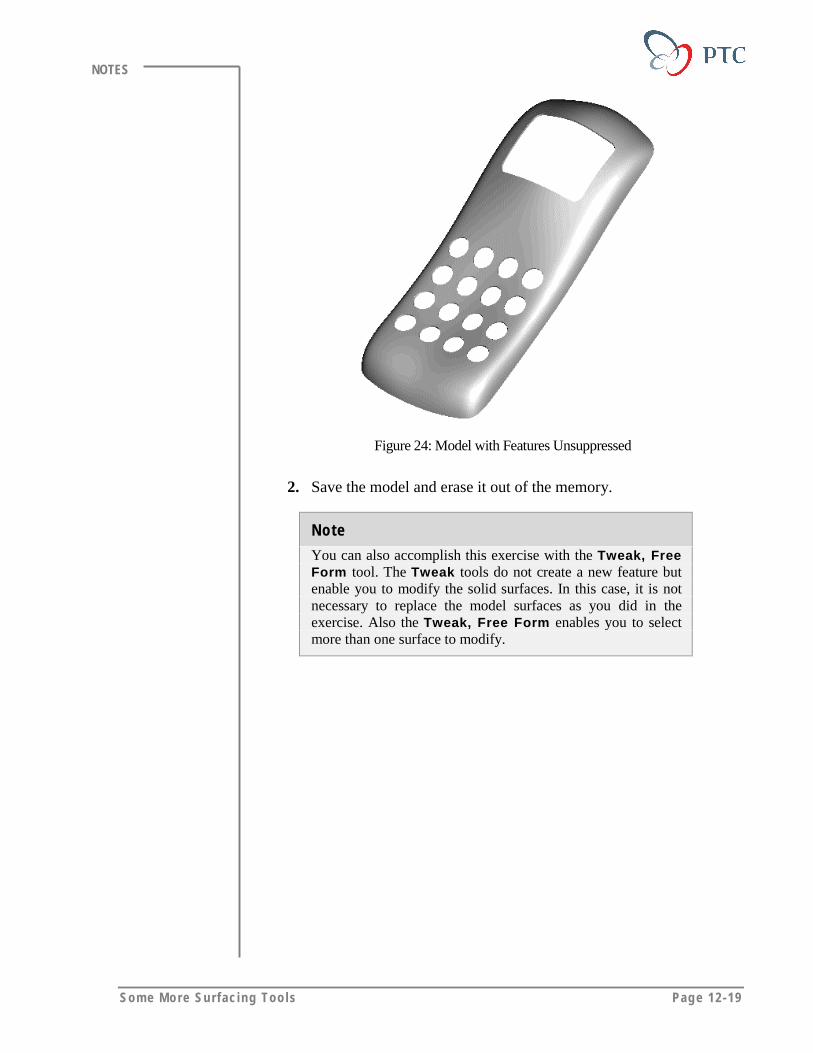
Some More Surfac ing Too ls Page 12-19
NOTES
Figure 24: Model with Features Unsuppressed
2. Save the model and erase it out of the memory.
Note
You can also accomplish this exercise with the Tweak, FreeForm tool. The Tweak tools do not create a new feature butenable you to modify the solid surfaces. In this case, it is notnecessary to replace the model surfaces as you did in theexercise. Also the Tweak, Free Form enables you to selectmore than one surface to modify.
Page 12-20 Des igning w i th Surfaces
NOTES
MODULE SUMMARYIn this module, you have learned that:
• To create a tangent surface between a curved surface/surfaces and asketched section, you can use the Section-to-Surface option.
• To create a draft surface between a draft line and a curved surface, youcan use the Tangent-to-Surface option.
• To create a smooth transition between two surfaces, you can use theSurface-to-Surface option.
• To dynamically push or pull on a surface and interactively change itsshape, you can use the Free Form option.

Page 13-1
Module
Working with Imported SurfacesIn this module, you learn how to use import surfaces.
Objectives
After completing this module, you will be able to:
• Define the use of the imported surfaces.
• Define the methods to work with imported surfaces.
• Fix the problem surfaces.
Page 13-2 Des igning w i th Surfaces
NOTES
WORKING WITH IMPORTED SURFACESYou can import various surface data including:
• Standard library parts, such as surface data from another CAD system.
• Surface geometry created by another department or company.
You can use the imported surfaces to:
• Create a solid model.
• Replace a solid surface.
• Replace an imported surface.
Creating a Solid Model from Surface Data
You can convert imported surface data into a solid model using thefollowing methods.
• If the individual quilts are merged as a single closed volume, you useProtrusion, Use Quilts� and Solid to create the solid feature.
• If the system displays the imported feature as an open quilt that cannotenclose a single volume, you use Protrusion, Use Quilts, and Thin tocreate a thin solid.
Replacing a Single Solid Surface with an Imported Quilt
If you import a styled surface into a working model, you can use thesurface to define solid geometry. Using Tweak and Replace, you can addmaterial and remove material simultaneously. This enables you to replacea single solid surface with a complex surface quilt.
Replacing & Updating Imported Surfaces
You can replace an imported surface feature with a new import filewithout a one-to-one correspondence between existing entities and thereplacement entities. The system prompts you to pair all entities of theimport feature referenced by any other features, both internal and externalto the part. Using the following options, you can replace all types ofimported geometry, such as wireframe, surfaces, edges, quilts, and datumpoints.
Work ing wi th Imported Surfaces Page 13-3
NOTES
You can:
• Replace the entire feature with the new import file using the ReplaceAll option.
• Replace selected parts of the feature with a new import file using theReplace option.
• Add or append the new geometry to the existing surface geometryusing the Add option.
Working MethodYou can use an imported 3-D wireframe, 3-D surface, or a combination ofthese data types to check a solid feature.
To use imported data in Pro/ENGINEER, you can use the following basicmethods:
• Use the geometry as imported. – If the geometry comes from astandard library of parts or from another department or company, thenyou may want to use the feature without changing it.
• Modify geometry non-parametrically. – If the geometry is modifiedoccasionally, you can modify the imported entities non-parametrically; for example, change the bend angle of a wireframebracket or move a snap mount on a surface model.
• Create/recreate only the important geometry. – If certain sectionsof the geometry need to be modified frequently, you can re-create onlythose sections. For example, a part used as a housing for electronicsmay need to attach to many different versions of the product.
• Re-create an entire model parametrically. – If the importedgeometry is altered extensively, it may be more efficient to re-createthe entire part, so that you can benefit from all of the advantages ofassociativity by capturing the design intent and using a feature-baseddesign.
WORKING WITH PROBLEM SURFACESOccasionally, imported geometry contains inconsistencies in topology ordiscontinuities in geometric entities. Pro/ENGINEER offers a set of toolsto repair these problems. You can repair these problems:
• During import of the surfaces.
• After import of the surfaces.
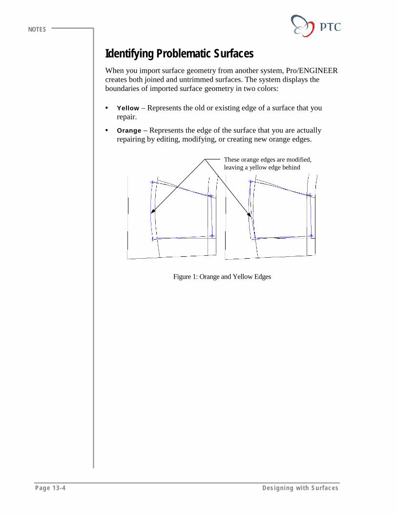
Page 13-4 Des igning w i th Surfaces
NOTES
Identifying Problematic SurfacesWhen you import surface geometry from another system, Pro/ENGINEERcreates both joined and untrimmed surfaces. The system displays theboundaries of imported surface geometry in two colors:
• Yellow – Represents the old or existing edge of a surface that yourepair.
• Orange – Represents the edge of the surface that you are actuallyrepairing by editing, modifying, or creating new orange edges.
These orange edges are modified,leaving a yellow edge behind
Figure 1: Orange and Yellow Edges
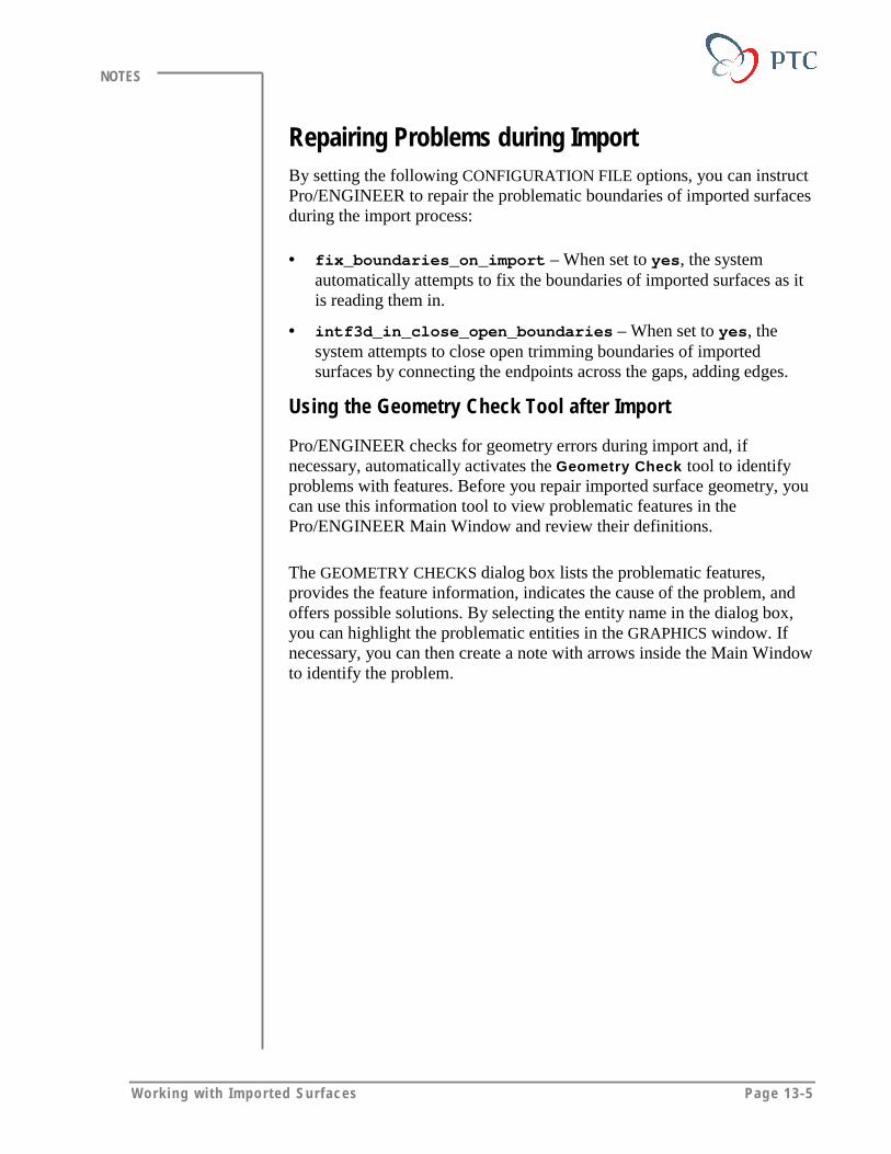
Work ing wi th Imported Surfaces Page 13-5
NOTES
Repairing Problems during ImportBy setting the following CONFIGURATION FILE options, you can instructPro/ENGINEER to repair the problematic boundaries of imported surfacesduring the import process:
• fix_boundaries_on_import – When set to yes, the systemautomatically attempts to fix the boundaries of imported surfaces as itis reading them in.
• intf3d_in_close_open_boundaries – When set to yes, thesystem attempts to close open trimming boundaries of importedsurfaces by connecting the endpoints across the gaps, adding edges.
Using the Geometry Check Tool after Import
Pro/ENGINEER checks for geometry errors during import and, ifnecessary, automatically activates the Geometry Check tool to identifyproblems with features. Before you repair imported surface geometry, youcan use this information tool to view problematic features in thePro/ENGINEER Main Window and review their definitions.
The GEOMETRY CHECKS dialog box lists the problematic features,provides the feature information, indicates the cause of the problem, andoffers possible solutions. By selecting the entity name in the dialog box,you can highlight the problematic entities in the GRAPHICS window. Ifnecessary, you can then create a note with arrows inside the Main Windowto identify the problem.
Page 13-6 Des igning w i th Surfaces
NOTES
Figure 2: Geometry Check Tool
Repairing the Imported GeometryAs an initial step, you can join surfaces using the Zip Gaps tool to closegaps between surfaces automatically. If, after zipping the gaps, theGeometry Check information tool identifies remaining problems with thesurface geometry, you can redefine the boundaries in various ways, aswell as exclude, delete, or create additional geometry, if necessary.
The following figure depicts the entire process to successfully repairproblematic surface geometry after import. Throughout the redefinitionprocess, however, you should repeatedly check your progress using theGeometry Check and Zip Gaps tools.

Work ing wi th Imported Surfaces Page 13-7
NOTES
Figure 3: Process for Repairing Problematic Surfaces
Using the Zip Gap Tool
After you import surfaces, the system may display some surfaces in themodel as one-sided surface edges (edges that are not shared by anothersurface) in yellow. Using the Zip Gap and Auto Select options, you canautomatically match yellow edges and join surfaces together.
Pro/ENGINEER automatically selects and highlights all of the pairs ofedge chains that fall within the tolerance of MaxGapDist. It then matchesthe surfaces along those chains and enables you to preview the newsurfaces.
You can add additional edges manually using Sel Chain, Single, orChain. However, if you are not satisfied with the results of the automaticsearch, you can reset the selection criteria and use Auto Select again. Byincreasing the maximum value of the selection range, you can force thesystem to include larger gaps in the selection.
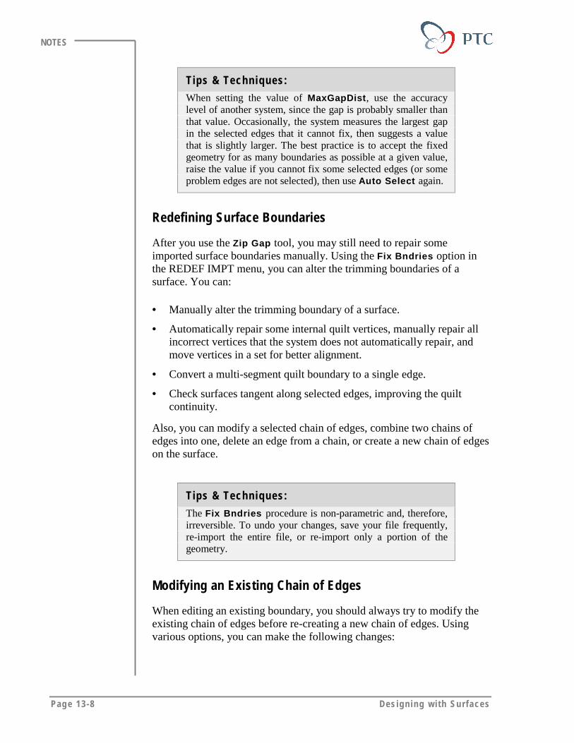
Page 13-8 Des igning w i th Surfaces
NOTES
Tips & Techniques:
When setting the value of MaxGapDist, use the accuracylevel of another system, since the gap is probably smaller thanthat value. Occasionally, the system measures the largest gapin the selected edges that it cannot fix, then suggests a valuethat is slightly larger. The best practice is to accept the fixedgeometry for as many boundaries as possible at a given value,raise the value if you cannot fix some selected edges (or someproblem edges are not selected), then use Auto Select again.
Redefining Surface Boundaries
After you use the Zip Gap tool, you may still need to repair someimported surface boundaries manually. Using the Fix Bndries option inthe REDEF IMPT menu, you can alter the trimming boundaries of asurface. You can:
• Manually alter the trimming boundary of a surface.
• Automatically repair some internal quilt vertices, manually repair allincorrect vertices that the system does not automatically repair, andmove vertices in a set for better alignment.
• Convert a multi-segment quilt boundary to a single edge.
• Check surfaces tangent along selected edges, improving the quiltcontinuity.
Also, you can modify a selected chain of edges, combine two chains ofedges into one, delete an edge from a chain, or create a new chain of edgeson the surface.
Tips & Techniques:
The Fix Bndries procedure is non-parametric and, therefore,irreversible. To undo your changes, save your file frequently,re-import the entire file, or re-import only a portion of thegeometry.
Modifying an Existing Chain of Edges
When editing an existing boundary, you should always try to modify theexisting chain of edges before re-creating a new chain of edges. Usingvarious options, you can make the following changes:

Work ing wi th Imported Surfaces Page 13-9
NOTES
• Move the vertex – You can place a vertex of the chain at a newreference point. The system then straightens the edges at the vertexand removes any preexisting tangency conditions at that vertex.
• Straighten an edge – You can replace a chain of edges with a simpletwo-point edge.
• Merge edges – You can merge the chain of edges into one continuousedge.
• Set the tangency condition – You can set or change tangencyconditions for the edge. The system marks the start and endpoints ofthe edge with corresponding arrows. You can make the edge tangent toa reference at the selected end, normal to a reference at the selectedend, or remove the requirement for the edge to be tangent or normal toa reference at the selected end.
• Split the edge – You can divide the edge into two edges at a selectedpoint. There are no tangency conditions between the two new sub-chains at that point.
Note:
You must replace a single open chain with a single open chain,or a single closed loop with a single closed loop before youexit the EDIT BNDRY menu; otherwise the system aborts thecurrent edit boundary procedure.
Move the vertex tonew location
Figure 4: Moving a Vertex
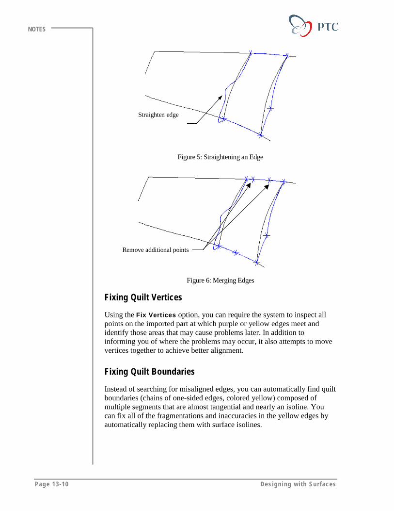
Page 13-10 Des igning w i th Surfaces
NOTES
Straighten edge
Figure 5: Straightening an Edge
Remove additional points
Figure 6: Merging Edges
Fixing Quilt Vertices
Using the Fix Vertices option, you can require the system to inspect allpoints on the imported part at which purple or yellow edges meet andidentify those areas that may cause problems later. In addition toinforming you of where the problems may occur, it also attempts to movevertices together to achieve better alignment.
Fixing Quilt Boundaries
Instead of searching for misaligned edges, you can automatically find quiltboundaries (chains of one-sided edges, colored yellow) composed ofmultiple segments that are almost tangential and nearly an isoline. Youcan fix all of the fragmentations and inaccuracies in the yellow edges byautomatically replacing them with surface isolines.

Work ing wi th Imported Surfaces Page 13-11
NOTES
Additionalvertex isremoved
Figure 7: Fixing Quilt Boundary
Fixing Tangency
You can improve the tangency of imported data by making surfacestangent along selected edges. The angle at which surfaces join is referredto as the dihedral angle. If the surfaces are meant to be tangent, the angleis very small or zero.
You can apply tangency only to small dihedral angles (that is, those thatare less than 10 degrees). The system automatically selects the edges thatare within the tolerance MaxDihedral and highlights them in blue.
You can add more edges manually using Sel Chain, Single, or Chain. Ifyou are not satisfied with the results of the automatic search, you can resetthe selection criteria and use Auto Select again. By increasing themaximum value of the selection range, the system will include largerdihedral angles in the selection.
Note:
The Fix Bndries tool automatically selects all problemboundaries based on the value of MaxDihedral. The systemdoes not automatically select boundaries that have gaps. Youshould use this method to repair a quilt that is completelyzipped and has fixed vertices.
Tips & Techniques for Editing Boundaries
When editing boundaries, follow these practices:
• Remember that the Fix Bndries procedure is nonparametric. Thisprocedure is not reversible. To undo your changes, re-import the file.
• Save the part often. You cannot undo changes after you exit the EDITBNDRY menu.
• Select accurately. Use Query Select to select the appropriate entities.

Page 13-12 Des igning w i th Surfaces
NOTES
• Modify whenever possible. Use the Modify option in the EDITBNDRY menu to change the existing edges rather than create newones.
• Always project edges onto the surface. You cannot create or modifyedges so that they are off of the surface. All new edges that you createand old edges that you modify should always project onto the surface.
• Exclude surfaces, if necessary. If you cannot repair a boundary orvertex using Fix Bndries, exclude the incorrect imported surfaces andblank them on a layer. Recreate new surfaces in Pro/ENGINEER andmerge them into the imported quilt.
• Fix edges manually, if necessary. If the Geometry Check informationis not available for a particular problem, isolate the problem area byfixing edges one at a time manually. With remaining problem edges,use the preceding techniques.
• Use available tools to investigate problems. Use the analysis toolsprovided by Pro/ENGINEER to investigate any problem geometry:
• Mesh surfaces to improve viewing. Cosmetic meshes can be helpful inimproving your view of surfaces that you need to edit.
Creating a New Chain of Edges
If you cannot modify an existing boundary, you can create a new chain ofedges by using any of the following methods:
• Projecting a curve or a chain of edges onto the surface.
• Connecting two or more points.
• Creating an isoline through a reference point.
• Intersecting the selected surface with another surface.
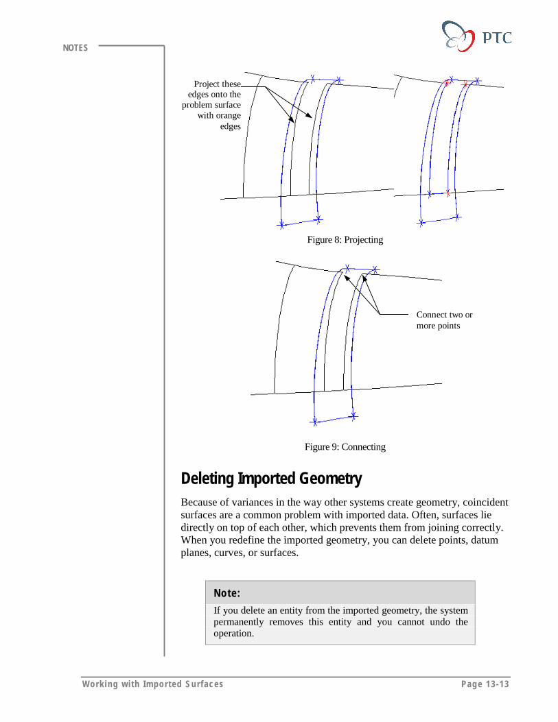
Work ing wi th Imported Surfaces Page 13-13
NOTES
Project theseedges onto the
problem surfacewith orange
edges
Figure 8: Projecting
Connect two ormore points
Figure 9: Connecting
Deleting Imported GeometryBecause of variances in the way other systems create geometry, coincidentsurfaces are a common problem with imported data. Often, surfaces liedirectly on top of each other, which prevents them from joining correctly.When you redefine the imported geometry, you can delete points, datumplanes, curves, or surfaces.
Note:
If you delete an entity from the imported geometry, the systempermanently removes this entity and you cannot undo theoperation.
Page 13-14 Des igning w i th Surfaces
NOTES
Excluding SurfacesInstead of using delete to remove a problematic imported surface, you cansimply exclude the surface. Since you do not permanently remove thesurface from the model, you can use it again in the future, if necessary.This method is particularly useful for resolving situations in which twosurfaces lie directly on top of each other, preventing them from joining therest of the quilt correctly. Pro/ENGINEER joins all other surfaces in thearea, with the exception of the one that you excluded.

Work ing wi th Imported Surfaces Page 13-15
NOTES
LABORATORY PRACTICALGoal
In this laboratory, you repair a problematic IGES surface and convert it
into a solid protrusion.
Method
In this exercise, you import an IGES file that is problematic then close thegaps using automatic selection of the imprecise surfaces. You manuallycorrect the boundaries of rest of the surfaces that are not corrected by autoselection.
ToolsIcon Description
Build feature
EXERCISE 1: Fixing Imported Surface Boundaries
Task 1. Create a new model using the ZIP.IGS file.
1. Click File > New. Type [zip_gaps] as the name, then click OK.
2. Click Insert > Data from File. Locate and select the ZIP.IGS filefrom the OPEN dialog box, then click Open.
3. Retain the default co-ordinate system and click OK in theCHOOSE SOLID OPTIONS AND PLACEMENT dialog box.
4. Review the INFORMATION WINDOW and close the window.
5. Observe the model in the wireframe mode. Notice that the modelcontains a number of unstitched surfaces having open (yellow)edges.
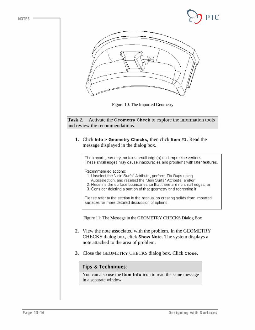
Page 13-16 Des igning w i th Surfaces
NOTES
Figure 10: The Imported Geometry
Task 2. Activate the Geometry Check to explore the information toolsand review the recommendations.
1. Click Info > Geometry Checks, then click Item #1. Read themessage displayed in the dialog box.
Figure 11: The Message in the GEOMETRY CHECKS Dialog Box
2. View the note associated with the problem. In the GEOMETRYCHECKS dialog box, click Show Note. The system displays anote attached to the area of problem.
3. Close the GEOMETRY CHECKS dialog box. Click Close.
Tips & Techniques:
You can also use the Item Info icon to read the same messagein a separate window.
Work ing wi th Imported Surfaces Page 13-17
NOTES
Task 3. Repair the quilt following the recommended action; firstremove the Join Surfs attribute and close all of the small gaps in thesurfaces.
4. Redefine the import feature. Click Feature > Redefine; then selectanywhere on the quilt.
5. Click Attributes, clear the Join Surfs option, and then clickDone/Return.
6. Close the gaps. Click Heal Geometry > Manual > Zip Gaps >Auto Select. Accept the selection. Click Zip Gaps.
Note:
When you use the Auto Select option, the systemautomatically selects all problematic boundaries based on thevalue of MaxGapDist. Once it has completed the selection, ithighlights the edges in blue. You can then add more edgesmanually using Sel Chain, Single, or Chain.
7. Use the geometry check tool to view the new warnings:
� Click Geometry Checks from the Info pull-down menu.
� In the GEOMETRY CHECKS dialog box, select Item #1and read the message in the dialog box.
� Similarly, select Item #2, Item #3, and Item #4 one afteranother and read the messages.
� Close the GEOMETRY CHECKS dialog box. Click Close.
8. Accept the changes and finish closing the gaps. Click Accept >Return > Done/Return.
9. Click Attributes, then select the Join Surfs check box, and thenclick Done/Return to reselect the Join Surfs attribute.
10. Click Done to finish correcting the surfaces.
11. Save the model.
Task 4. Examine the model that is corrected.
1. Examine the model. Notice that the some of the surfaces, shown asmeshed in the following figure, still have open edges and have not
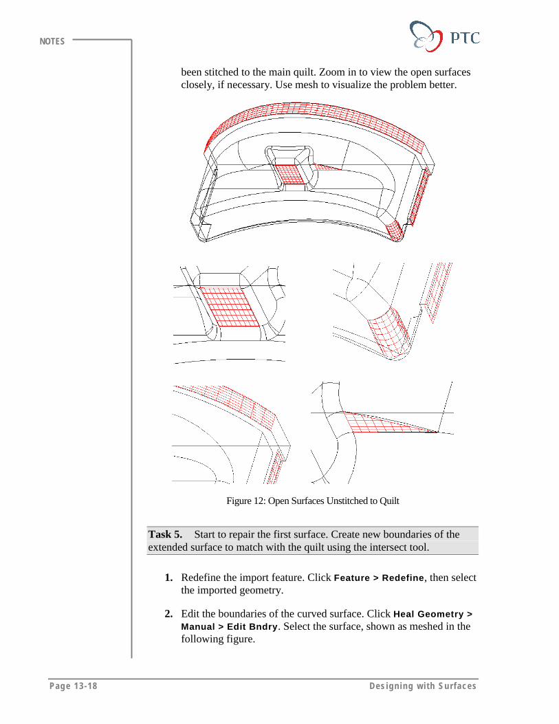
Page 13-18 Des igning w i th Surfaces
NOTES
been stitched to the main quilt. Zoom in to view the open surfacesclosely, if necessary. Use mesh to visualize the problem better.
Figure 12: Open Surfaces Unstitched to Quilt
Task 5. Start to repair the first surface. Create new boundaries of theextended surface to match with the quilt using the intersect tool.
1. Redefine the import feature. Click Feature > Redefine, then selectthe imported geometry.
2. Edit the boundaries of the curved surface. Click Heal Geometry >Manual > Edit Bndry. Select the surface, shown as meshed in thefollowing figure.
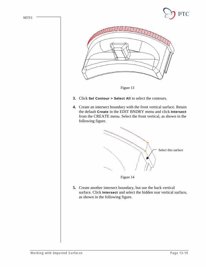
Work ing wi th Imported Surfaces Page 13-19
NOTES
Figure 13
3. Click Sel Contour > Select All to select the contours.
4. Create an intersect boundary with the front vertical surface. Retainthe default Create in the EDIT BNDRY menu and click Intersectfrom the CREATE menu. Select the front vertical, as shown in thefollowing figure.
Select this surface
Figure 14
5. Create another intersect boundary, but use the back verticalsurface. Click Intersect and select the hidden rear vertical surface,as shown in the following figure.
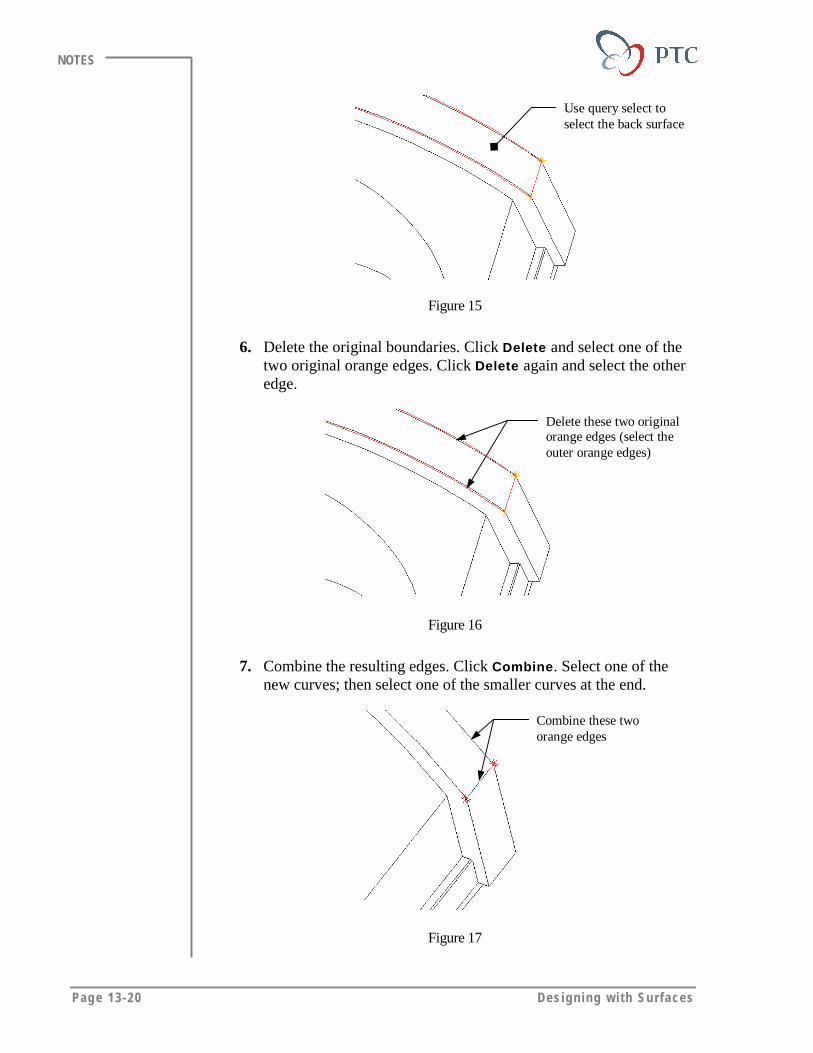
Page 13-20 Des igning w i th Surfaces
NOTES
Use query select toselect the back surface
Figure 15
6. Delete the original boundaries. Click Delete and select one of thetwo original orange edges. Click Delete again and select the otheredge.
Delete these two originalorange edges (select theouter orange edges)
Figure 16
7. Combine the resulting edges. Click Combine. Select one of thenew curves; then select one of the smaller curves at the end.
Combine these twoorange edges
Figure 17
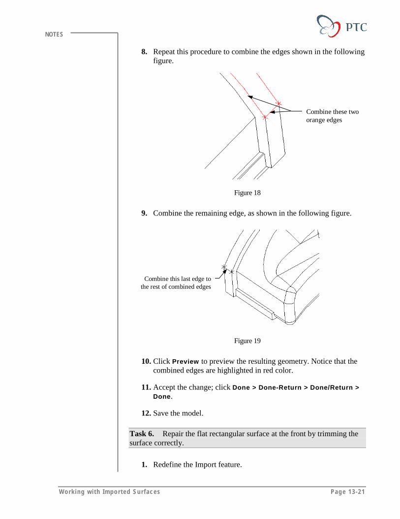
Work ing wi th Imported Surfaces Page 13-21
NOTES
8. Repeat this procedure to combine the edges shown in the followingfigure.
Combine these twoorange edges
Figure 18
9. Combine the remaining edge, as shown in the following figure.
Combine this last edge tothe rest of combined edges
Figure 19
10. Click Preview to preview the resulting geometry. Notice that thecombined edges are highlighted in red color.
11. Accept the change; click Done > Done-Return > Done/Return >Done.
12. Save the model.
Task 6. Repair the flat rectangular surface at the front by trimming thesurface correctly.
1. Redefine the Import feature.

Page 13-22 Des igning w i th Surfaces
NOTES
2. Edit the boundaries of the flat surface. Click Heal Geometry >Manual > Edit Bndry. Select the surface, shown as meshed in thefollowing figure.
Figure 20
3. Click Sel Contour > Select All.
4. Reposition the vertices of the surface correctly: Click Modify >Move Vertex. Select any one of the orange vertexes, then selectthe yellow vertex closest to the first selection.
5. Observe the change. Notice that the orange edge updates to reflectthe new selection.
Move this orangecross vertex to thenext yellowvertex
Figure 21
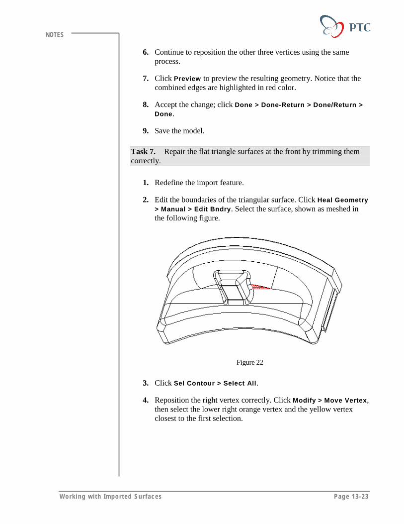
Work ing wi th Imported Surfaces Page 13-23
NOTES
6. Continue to reposition the other three vertices using the sameprocess.
7. Click Preview to preview the resulting geometry. Notice that thecombined edges are highlighted in red color.
8. Accept the change; click Done > Done-Return > Done/Return >Done.
9. Save the model.
Task 7. Repair the flat triangle surfaces at the front by trimming themcorrectly.
1. Redefine the import feature.
2. Edit the boundaries of the triangular surface. Click Heal Geometry> Manual > Edit Bndry. Select the surface, shown as meshed inthe following figure.
Figure 22
3. Click Sel Contour > Select All.
4. Reposition the right vertex correctly. Click Modify > Move Vertex,then select the lower right orange vertex and the yellow vertexclosest to the first selection.
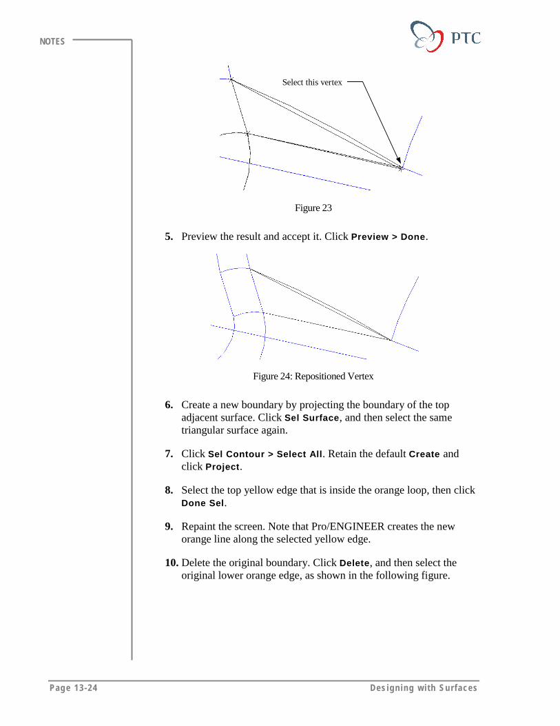
Page 13-24 Des igning w i th Surfaces
NOTES
Select this vertex
Figure 23
5. Preview the result and accept it. Click Preview > Done.
Figure 24: Repositioned Vertex
6. Create a new boundary by projecting the boundary of the topadjacent surface. Click Sel Surface, and then select the sametriangular surface again.
7. Click Sel Contour > Select All. Retain the default Create andclick Project.
8. Select the top yellow edge that is inside the orange loop, then clickDone Sel.
9. Repaint the screen. Note that Pro/ENGINEER creates the neworange line along the selected yellow edge.
10. Delete the original boundary. Click Delete, and then select theoriginal lower orange edge, as shown in the following figure.
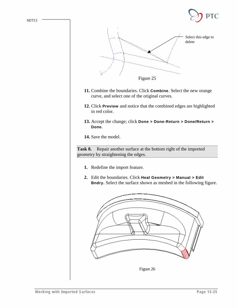
Work ing wi th Imported Surfaces Page 13-25
NOTES
Select this edge todelete
Figure 25
11. Combine the boundaries. Click Combine. Select the new orangecurve, and select one of the original curves.
12. Click Preview and notice that the combined edges are highlightedin red color.
13. Accept the change; click Done > Done-Return > Done/Return >Done.
14. Save the model.
Task 8. Repair another surface at the bottom right of the importedgeometry by straightening the edges.
1. Redefine the import feature.
2. Edit the boundaries. Click Heal Geometry > Manual > EditBndry. Select the surface shown as meshed in the following figure.
Figure 26
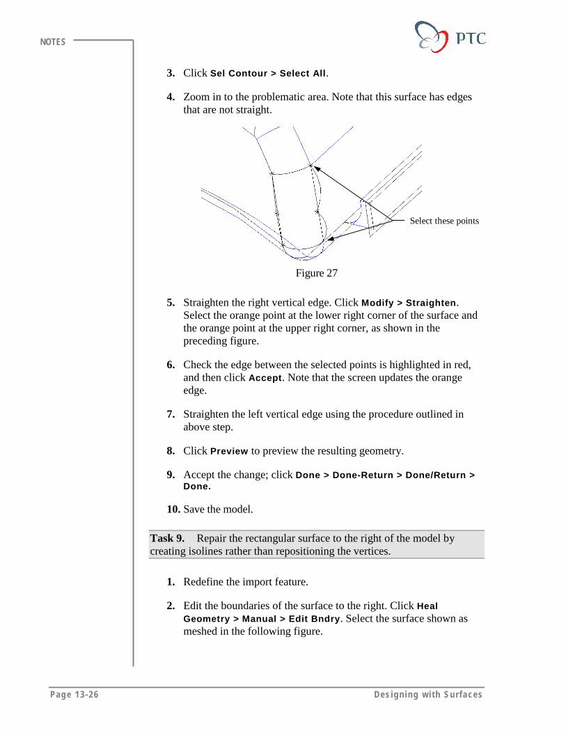
Page 13-26 Des igning w i th Surfaces
NOTES
3. Click Sel Contour > Select All.
4. Zoom in to the problematic area. Note that this surface has edgesthat are not straight.
Select these points
Figure 27
5. Straighten the right vertical edge. Click Modify > Straighten.Select the orange point at the lower right corner of the surface andthe orange point at the upper right corner, as shown in thepreceding figure.
6. Check the edge between the selected points is highlighted in red,and then click Accept. Note that the screen updates the orangeedge.
7. Straighten the left vertical edge using the procedure outlined inabove step.
8. Click Preview to preview the resulting geometry.
9. Accept the change; click Done > Done-Return > Done/Return >Done.
10. Save the model.
Task 9. Repair the rectangular surface to the right of the model bycreating isolines rather than repositioning the vertices.
1. Redefine the import feature.
2. Edit the boundaries of the surface to the right. Click HealGeometry > Manual > Edit Bndry. Select the surface shown asmeshed in the following figure.
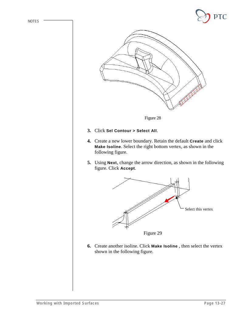
Work ing wi th Imported Surfaces Page 13-27
NOTES
Figure 28
3. Click Sel Contour > Select All.
4. Create a new lower boundary. Retain the default Create and clickMake Isoline. Select the right bottom vertex, as shown in thefollowing figure.
5. Using Next, change the arrow direction, as shown in the followingfigure. Click Accept.
Select this vertex
Figure 29
6. Create another isoline. Click Make Isoline , then select the vertexshown in the following figure.

Page 13-28 Des igning w i th Surfaces
NOTES
Figure 30
7. Use the same method to create next two isolines lying on top of theyellow edges.
Figure 31
8. Delete the original boundaries.
Figure 32
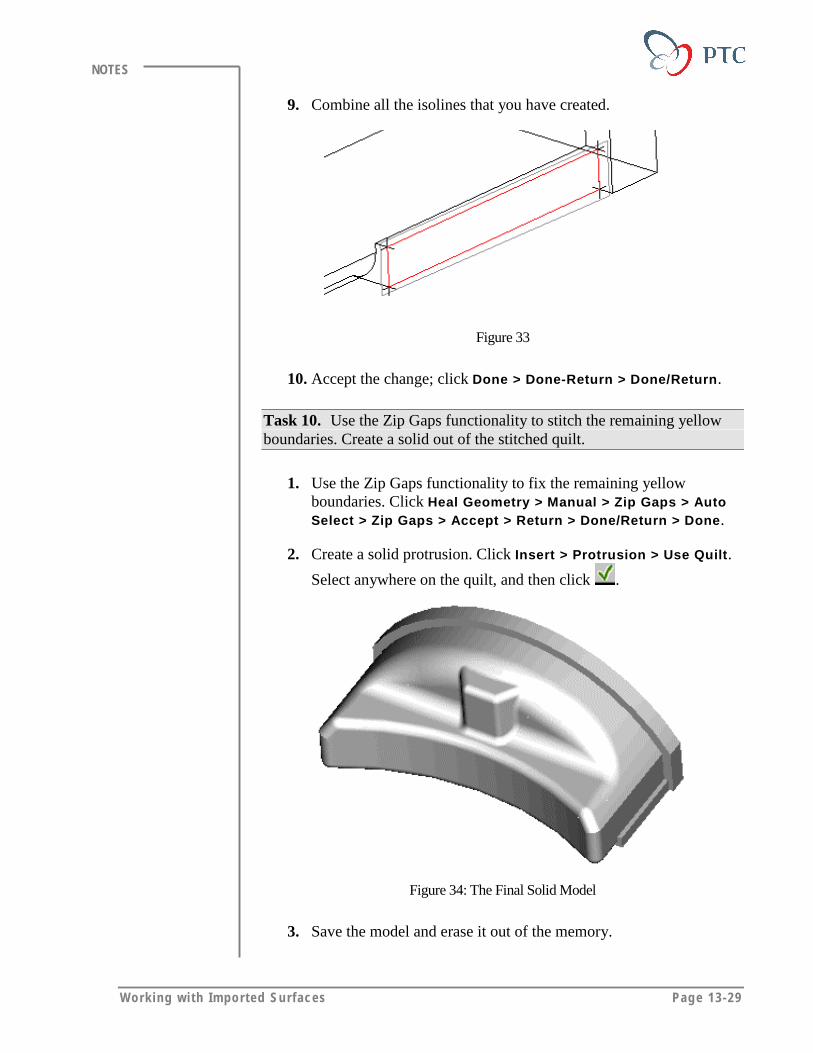
Work ing wi th Imported Surfaces Page 13-29
NOTES
9. Combine all the isolines that you have created.
Figure 33
10. Accept the change; click Done > Done-Return > Done/Return.
Task 10. Use the Zip Gaps functionality to stitch the remaining yellowboundaries. Create a solid out of the stitched quilt.
1. Use the Zip Gaps functionality to fix the remaining yellowboundaries. Click Heal Geometry > Manual > Zip Gaps > AutoSelect > Zip Gaps > Accept > Return > Done/Return > Done.
2. Create a solid protrusion. Click Insert > Protrusion > Use Quilt.
Select anywhere on the quilt, and then click .
Figure 34: The Final Solid Model
3. Save the model and erase it out of the memory.
Page 13-30 Des igning w i th Surfaces
NOTES
MODULE SUMMARYIn this module, you have learned that:
• You can use imported data to:
� Create a solid model.
� Replace a solid surface.
� Replace an imported surface
• You can use the following methods to work with imported data:
� Use the geometry as imported.
� Modify geometry non-parametrically.
� Create/recreate important geometry only
� Re-create an entire model parametrically.
• Pro/ENGINEER checks for geometry errors during import and offerspossible solutions to fix the problems.
• Pro/ENGINEER also offers possible solutions while you are fixing theproblems.
• Pro/ENGINEER offers many tools to:
� Close gaps.
� Redefine surface boundaries.
� Fix tangency.
Page A-1
Appendix
Additional ExercisesIn this module, you practice with advanced surface design methods.
Objectives
After completing this module, you will be able to:
• Create an involute surface using relations.
• Create a gear sector using involute surfaces to cut the gear profile.
• Create a helical cut using variable section sweep.
• Create a complex round using surfaces.
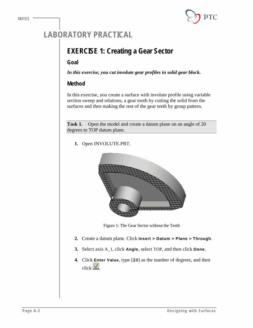
Page A-2 Des igning w i th Surfaces
NOTES
LABORATORY PRACTICAL
EXERCISE 1: Creating a Gear SectorGoal
In this exercise, you cut involute gear profiles in solid gear block.
Method
In this exercise, you create a surface with involute profile using variablesection sweep and relations, a gear tooth by cutting the solid from thesurfaces and then making the rest of the gear teeth by group pattern.
Task 1. Open the model and create a datum plane on an angle of 20degrees to TOP datum plane.
1. Open INVOLUTE.PRT.
Figure 1: The Gear Sector without the Teeth
2. Create a datum plane. Click Insert > Datum > Plane > Through.
3. Select axis A_1, click Angle, select TOP, and then click Done.
4. Click Enter Value, type [20] as the number of degrees, and then
click .
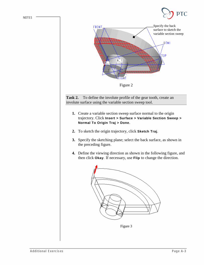
Addi t ional Exerc ises Page A-3
NOTES
Specify the backsurface to sketch thevariable section sweep
Figure 2
Task 2. To define the involute profile of the gear tooth, create aninvolute surface using the variable section sweep tool.
1. Create a variable section sweep surface normal to the origintrajectory. Click Insert > Surface > Variable Section Sweep >Normal To Origin Traj > Done.
2. To sketch the origin trajectory, click Sketch Traj.
3. Specify the sketching plane; select the back surface, as shown inthe preceding figure.
4. Define the viewing direction as shown in the following figure, andthen click Okay. If necessary, use Flip to change the direction.
Figure 3
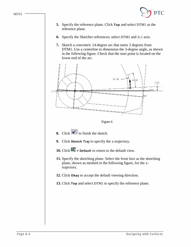
Page A-4 Des igning w i th Surfaces
NOTES
5. Specify the reference plane. Click Top and select DTM1 as thereference plane.
6. Specify the Sketcher references; select DTM1 and A-1 axis.
7. Sketch a concentric 14-degree arc that starts 3 degrees fromDTM1. Use a centerline to dimension the 3-degree angle, as shownin the following figure. Check that the start point is located on thelower end of the arc.
Figure 4
8. Click to finish the sketch.
9. Click Sketch Traj to specify the x-trajectory.
10. Click > Default to return to the default view.
11. Specify the sketching plane. Select the front face as the sketchingplane, shown as meshed in the following figure, for the x-trajectory.
12. Click Okay to accept the default viewing direction.
13. Click Top and select DTM1 to specify the reference plane.

Addi t ional Exerc ises Page A-5
NOTES
Figure 5
14. Specify the Sketcher references; select DTM1 and A-1 axis.
15. Create the same sketch as created in the previous step.
Tips & Techniques:
The second trajectory will have the same dimensions as thefirst. Do not start your second sketch exactly on top of thefirst; instead, allow the final modification of the dimensions tocause them to coincide in the sketching view. To complete thesketch, you may want to refer to the default view.
16. Click to finish the sketch.
17. Do not define another trajectory. Click Done.
18. Specify the attributes. Click Open Ends >Done.
Task 3. Sketch the cross section.
1. Define additional references select the edges, as shown in thefollowing figure.
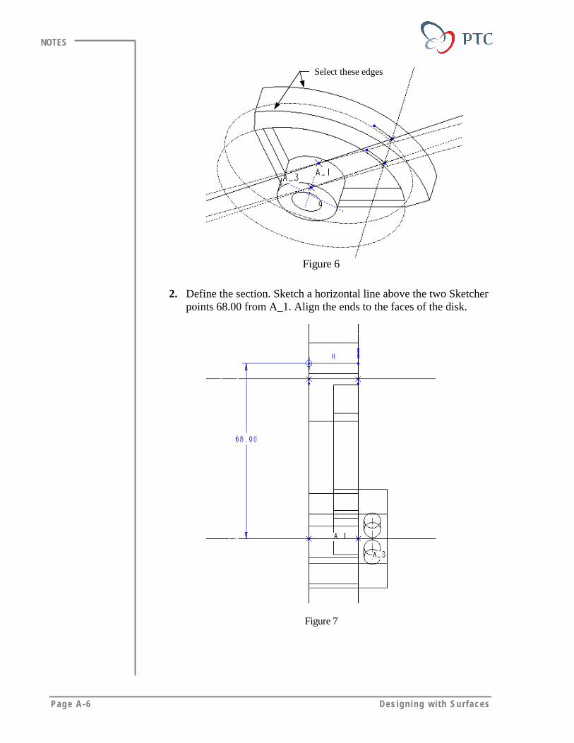
Page A-6 Des igning w i th Surfaces
NOTES
Select these edges
Figure 6
2. Define the section. Sketch a horizontal line above the two Sketcherpoints 68.00 from A_1. Align the ends to the faces of the disk.
Figure 7
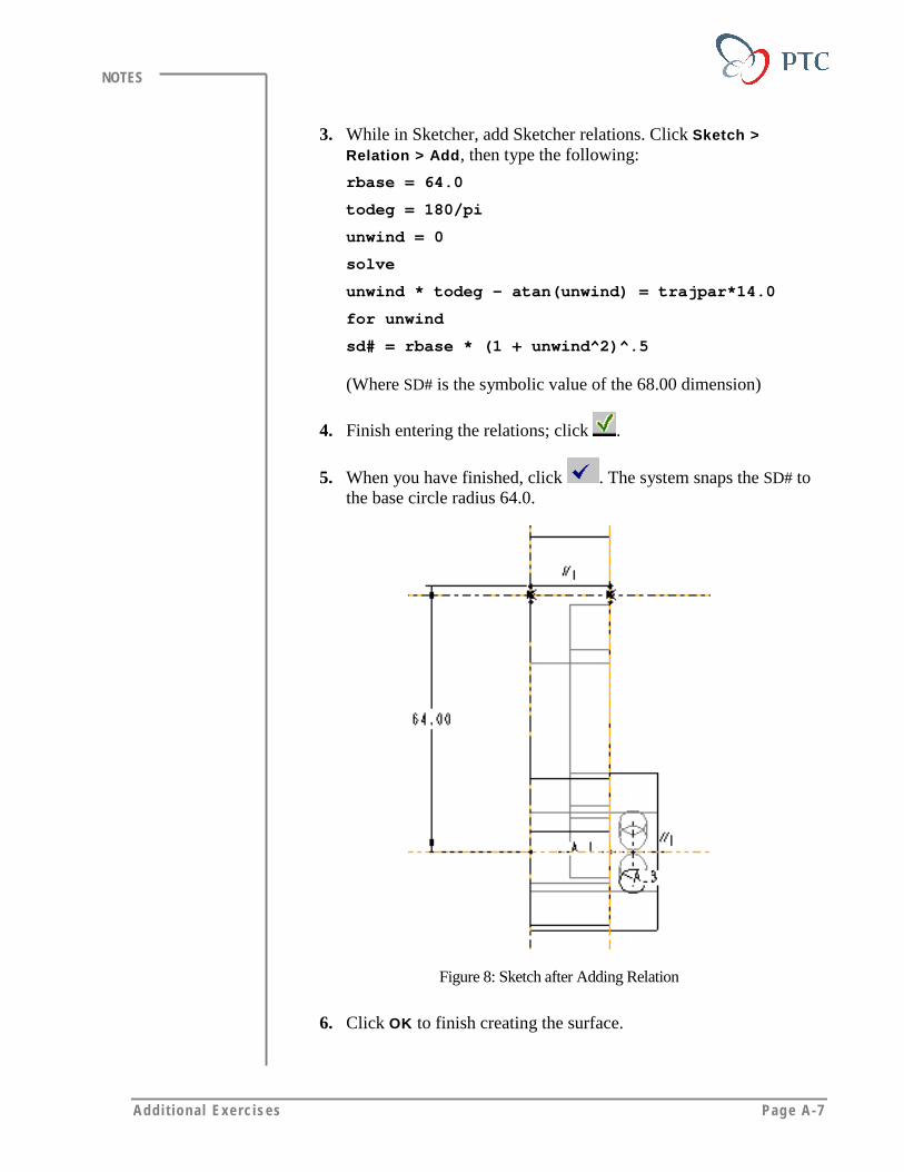
Addi t ional Exerc ises Page A-7
NOTES
3. While in Sketcher, add Sketcher relations. Click Sketch >Relation > Add, then type the following:
rbase = 64.0
todeg = 180/pi
unwind = 0
solve
unwind * todeg - atan(unwind) = trajpar*14.0
for unwind
sd# = rbase * (1 + unwind^2)^.5
(Where SD# is the symbolic value of the 68.00 dimension)
4. Finish entering the relations; click .
5. When you have finished, click . The system snaps the SD# tothe base circle radius 64.0.
Figure 8: Sketch after Adding Relation
6. Click OK to finish creating the surface.
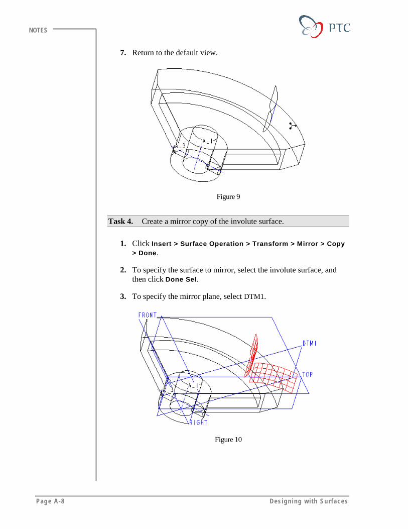
Page A-8 Des igning w i th Surfaces
NOTES
7. Return to the default view.
Figure 9
Task 4. Create a mirror copy of the involute surface.
1. Click Insert > Surface Operation > Transform > Mirror > Copy> Done.
2. To specify the surface to mirror, select the involute surface, andthen click Done Sel.
3. To specify the mirror plane, select DTM1.
Figure 10
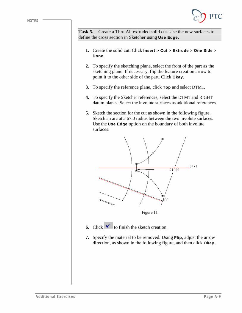
Addi t ional Exerc ises Page A-9
NOTES
Task 5. Create a Thru All extruded solid cut. Use the new surfaces todefine the cross section in Sketcher using Use Edge.
1. Create the solid cut. Click Insert > Cut > Extrude > One Side >Done.
2. To specify the sketching plane, select the front of the part as thesketching plane. If necessary, flip the feature creation arrow topoint it to the other side of the part. Click Okay.
3. To specify the reference plane, click Top and select DTM1.
4. To specify the Sketcher references, select the DTM1 and RIGHTdatum planes. Select the involute surfaces as additional references.
5. Sketch the section for the cut as shown in the following figure.Sketch an arc at a 67.0 radius between the two involute surfaces.Use the Use Edge option on the boundary of both involutesurfaces.
Figure 11
6. Click to finish the sketch creation.
7. Specify the material to be removed. Using Flip, adjust the arrowdirection, as shown in the following figure, and then click Okay.
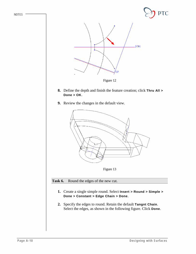
Page A-10 Des igning w i th Surfaces
NOTES
Figure 12
8. Define the depth and finish the feature creation; click Thru All >Done > OK.
9. Review the changes in the default view.
Figure 13
Task 6. Round the edges of the new cut.
1. Create a single simple round. Select Insert > Round > Simple >Done > Constant > Edge Chain > Done.
2. Specify the edges to round. Retain the default Tangnt Chain.Select the edges, as shown in the following figure. Click Done.
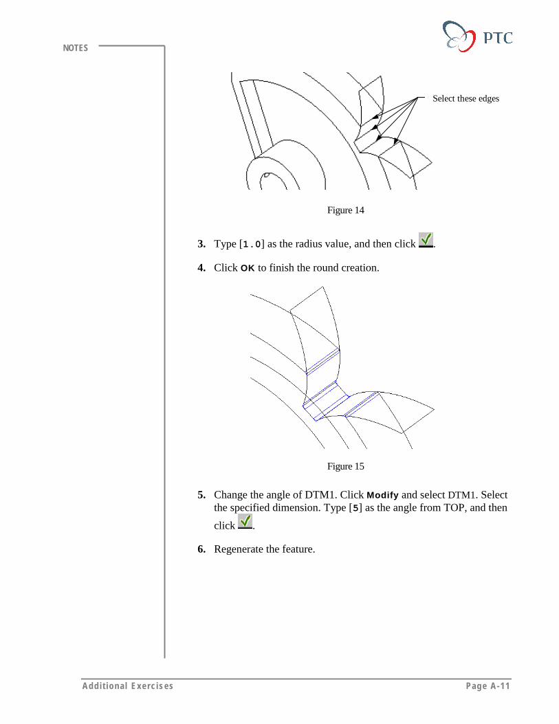
Addi t ional Exerc ises Page A-11
NOTES
Select these edges
Figure 14
3. Type [1.0] as the radius value, and then click .
4. Click OK to finish the round creation.
Figure 15
5. Change the angle of DTM1. Click Modify and select DTM1. Selectthe specified dimension. Type [5] as the angle from TOP, and then
click .
6. Regenerate the feature.
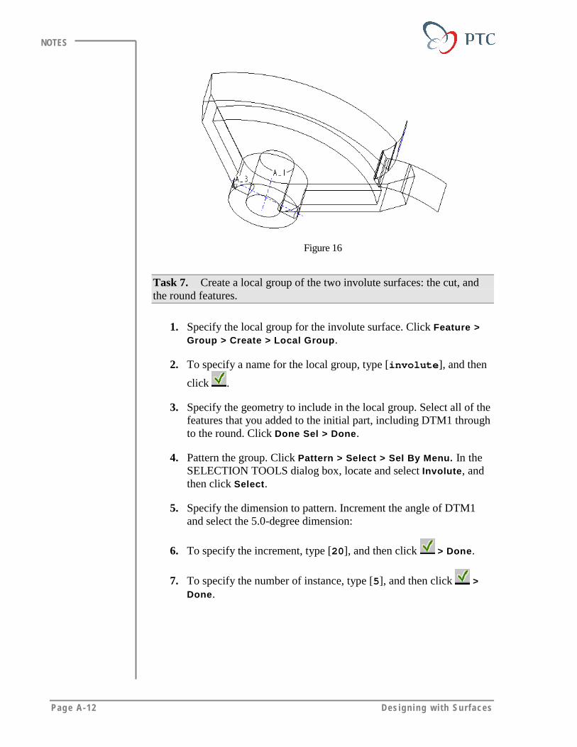
Page A-12 Des igning w i th Surfaces
NOTES
Figure 16
Task 7. Create a local group of the two involute surfaces: the cut, andthe round features.
1. Specify the local group for the involute surface. Click Feature >Group > Create > Local Group.
2. To specify a name for the local group, type [involute], and then
click .
3. Specify the geometry to include in the local group. Select all of thefeatures that you added to the initial part, including DTM1 throughto the round. Click Done Sel > Done.
4. Pattern the group. Click Pattern > Select > Sel By Menu. In theSELECTION TOOLS dialog box, locate and select Involute, andthen click Select.
5. Specify the dimension to pattern. Increment the angle of DTM1and select the 5.0-degree dimension:
6. To specify the increment, type [20], and then click > Done.
7. To specify the number of instance, type [5], and then click >Done.
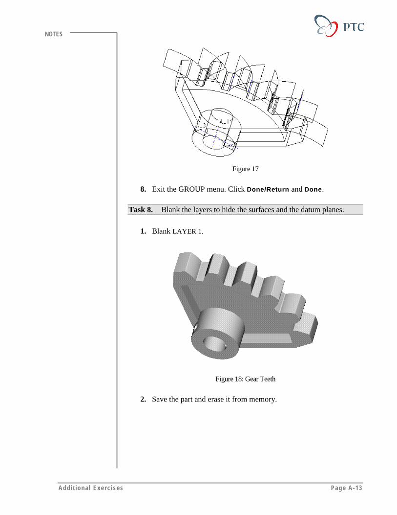
Addi t ional Exerc ises Page A-13
NOTES
Figure 17
8. Exit the GROUP menu. Click Done/Return and Done.
Task 8. Blank the layers to hide the surfaces and the datum planes.
1. Blank LAYER 1.
Figure 18: Gear Teeth
2. Save the part and erase it from memory.
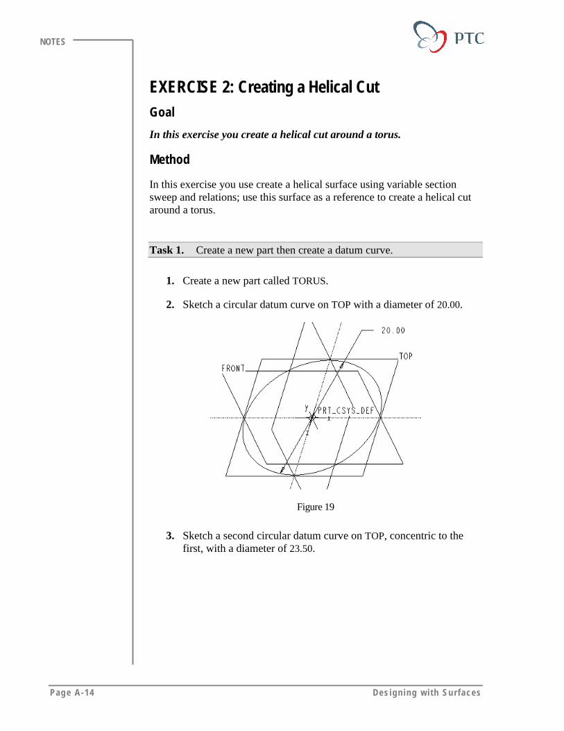
Page A-14 Des igning w i th Surfaces
NOTES
EXERCISE 2: Creating a Helical CutGoal
In this exercise you create a helical cut around a torus.
Method
In this exercise you use create a helical surface using variable sectionsweep and relations; use this surface as a reference to create a helical cutaround a torus.
Task 1. Create a new part then create a datum curve.
1. Create a new part called TORUS.
2. Sketch a circular datum curve on TOP with a diameter of 20.00.
Figure 19
3. Sketch a second circular datum curve on TOP, concentric to thefirst, with a diameter of 23.50.

Addi t ional Exerc ises Page A-15
NOTES
Figure 20
4. Create a datum point. Using Curve X Srf, create a datum pointwhere the larger circular curve and FRONT cross, as shown in thefollowing figure.
Figure 21
Task 2. Create a solid protrusion.
1. To create a solid protrusion, click Insert > Protrusion > Sweep >Select Traj > Curve Chain. Select the inner circular curve, andthen click Select All. Check that the start point is adjacent to thedatum point as shown in the following figure. Click Done > NoInn Fcs > Done.
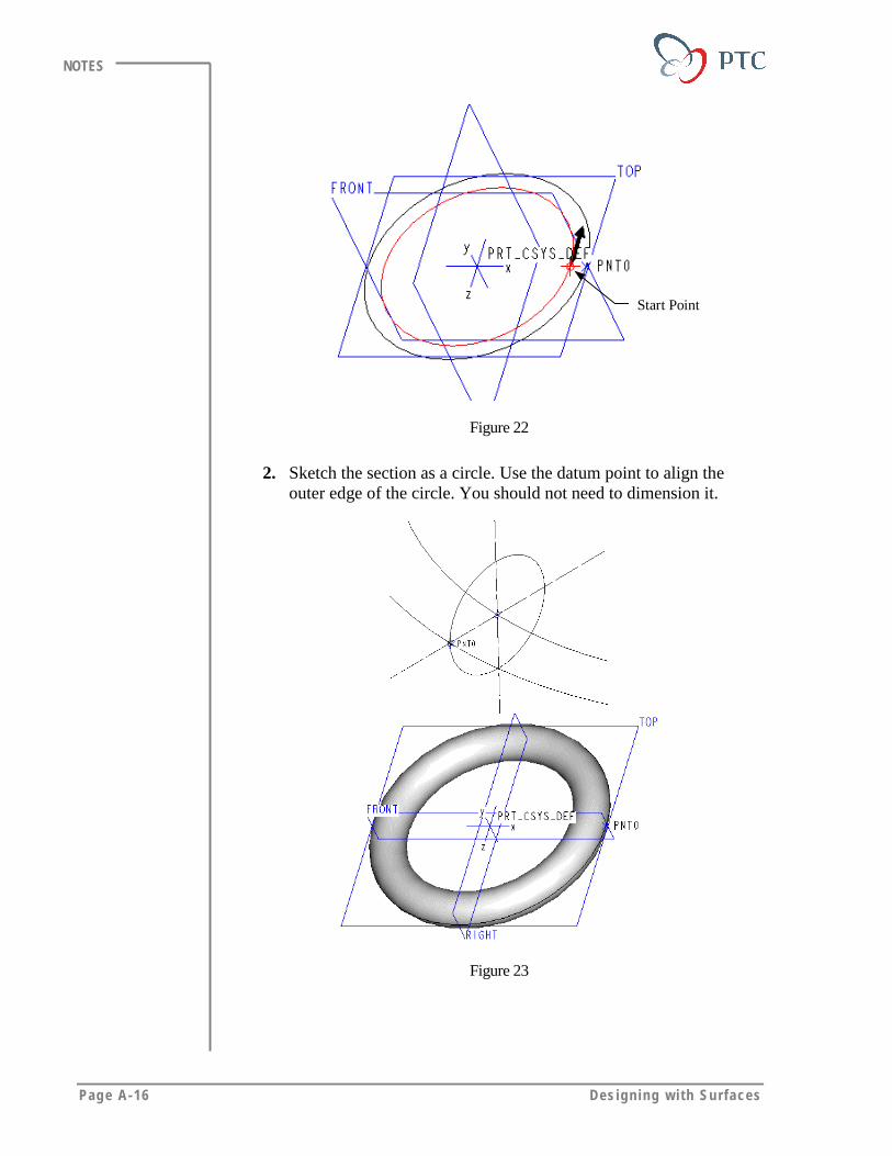
Page A-16 Des igning w i th Surfaces
NOTES
Start Point
Figure 22
2. Sketch the section as a circle. Use the datum point to align theouter edge of the circle. You should not need to dimension it.
Figure 23
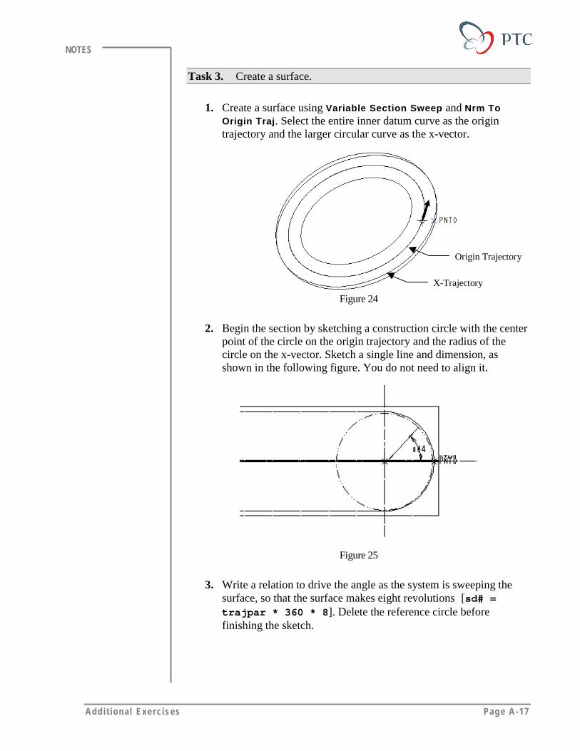
Addi t ional Exerc ises Page A-17
NOTES
Task 3. Create a surface.
1. Create a surface using Variable Section Sweep and Nrm ToOrigin Traj. Select the entire inner datum curve as the origintrajectory and the larger circular curve as the x-vector.
Origin Trajectory
X-Trajectory
Figure 24
2. Begin the section by sketching a construction circle with the centerpoint of the circle on the origin trajectory and the radius of thecircle on the x-vector. Sketch a single line and dimension, asshown in the following figure. You do not need to align it.
Figure 25
3. Write a relation to drive the angle as the system is sweeping thesurface, so that the surface makes eight revolutions [sd# =trajpar * 360 * 8]. Delete the reference circle beforefinishing the sketch.

Page A-18 Des igning w i th Surfaces
NOTES
Figure 26
Task 4. Create a solid cut.
1. Create a solid cut using the Sweep and Select Traj options.Specify the trajectory. Click Tangnt Chain. Select the visible,yellow edge of the spiral surface, then click Done.
Figure 27
2. Accept the default direction for the upward horizontal plane of thesweep. Sketch the section with a diameter of 1.75, as shown in thefollowing figure. Remove the material from the center of the circle.

Addi t ional Exerc ises Page A-19
NOTES
Figure 28
3. Return to the default view.
4. Blank the default curve and surface layers to view the solid cut.
Figure 29: Finished Part
5. Save the part and erase it from memory.
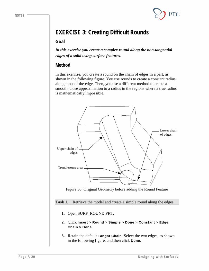
Page A-20 Des igning w i th Surfaces
NOTES
EXERCISE 3: Creating Difficult RoundsGoal
In this exercise you create a complex round along the non-tangential
edges of a solid using surface features.
Method
In this exercise, you create a round on the chain of edges in a part, asshown in the following figure. You use rounds to create a constant radiusalong most of the edge. Then, you use a different method to create asmooth, close approximation to a radius in the regions where a true radiusis mathematically impossible.
Upper chain ofedges
Lower chainof edges
Troublesome area
Figure 30: Original Geometry before adding the Round Feature
Task 1. Retrieve the model and create a simple round along the edges.
1. Open SURF_ROUND.PRT.
2. Click Insert > Round > Simple > Done > Constant > EdgeChain > Done.
3. Retain the default Tangnt Chain. Select the two edges, as shownin the following figure, and then click Done.
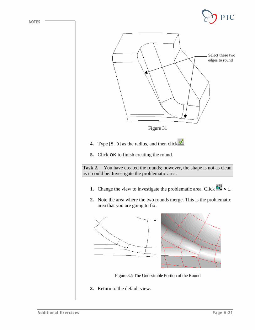
Addi t ional Exerc ises Page A-21
NOTES
Select these twoedges to round
Figure 31
4. Type [5.0] as the radius, and then click .
5. Click OK to finish creating the round.
Task 2. You have created the rounds; however, the shape is not as cleanas it could be. Investigate the problematic area.
1. Change the view to investigate the problematic area. Click > 1.
2. Note the area where the two rounds merge. This is the problematicarea that you are going to fix.
Figure 32: The Undesirable Portion of the Round
3. Return to the default view.
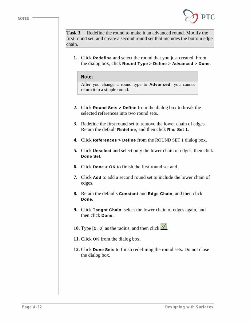
Page A-22 Des igning w i th Surfaces
NOTES
Task 3. Redefine the round to make it an advanced round. Modify thefirst round set, and create a second round set that includes the bottom edgechain.
1. Click Redefine and select the round that you just created. Fromthe dialog box, click Round Type > Define > Advanced > Done.
Note:
After you change a round type to Advanced, you cannotreturn it to a simple round.
2. Click Round Sets > Define from the dialog box to break theselected references into two round sets.
3. Redefine the first round set to remove the lower chain of edges.Retain the default Redefine, and then click Rnd Set 1.
4. Click References > Define from the ROUND SET 1 dialog box.
5. Click Unselect and select only the lower chain of edges, then clickDone Sel.
6. Click Done > OK to finish the first round set and.
7. Click Add to add a second round set to include the lower chain ofedges.
8. Retain the defaults Constant and Edge Chain, and then clickDone.
9. Click Tangnt Chain, select the lower chain of edges again, andthen click Done.
10. Type [5.0] as the radius, and then click .
11. Click OK from the dialog box.
12. Click Done Sets to finish redefining the round sets. Do not closethe dialog box.

Addi t ional Exerc ises Page A-23
NOTES
Task 4. Create a surface instead of a solid feature to clean up thetransition area between the two sets.
1. Change both the attachment type and transition between the sets toa surface. Press <CTRL>, click Transitions and Attach Type fromthe dialog box, then click Define.
2. Create stop transitions for both round sets. Click Add by Type >Stop >Done.
3. Select one of the green ends of the two round sets where they meet,as shown in the following figure, and then click Done.
4. Select the other green end, and then click Done > Done Trans.
Specify these twogreen edges
Figure 33
5. Click Make Surface > Done to create a surface instead of a solid.
6. Click OK to finish redefining the round. The model should displayas shown in the following figure.
Figure 34
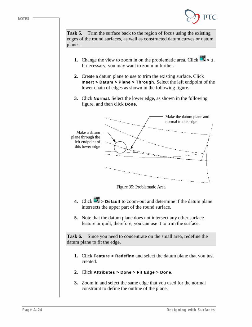
Page A-24 Des igning w i th Surfaces
NOTES
Task 5. Trim the surface back to the region of focus using the existingedges of the round surfaces, as well as constructed datum curves or datumplanes.
1. Change the view to zoom in on the problematic area. Click > 1.If necessary, you may want to zoom in further.
2. Create a datum plane to use to trim the existing surface. ClickInsert > Datum > Plane > Through. Select the left endpoint of thelower chain of edges as shown in the following figure.
3. Click Normal. Select the lower edge, as shown in the followingfigure, and then click Done.
Make a datumplane through the
left endpoint ofthis lower edge
Make the datum plane andnormal to this edge
Figure 35: Problematic Area
4. Click > Default to zoom-out and determine if the datum planeintersects the upper part of the round surface.
5. Note that the datum plane does not intersect any other surfacefeature or quilt, therefore, you can use it to trim the surface.
Task 6. Since you need to concentrate on the small area, redefine thedatum plane to fit the edge.
1. Click Feature > Redefine and select the datum plane that you justcreated.
2. Click Attributes > Done > Fit Edge > Done.
3. Zoom in and select the same edge that you used for the normalconstraint to define the outline of the plane.
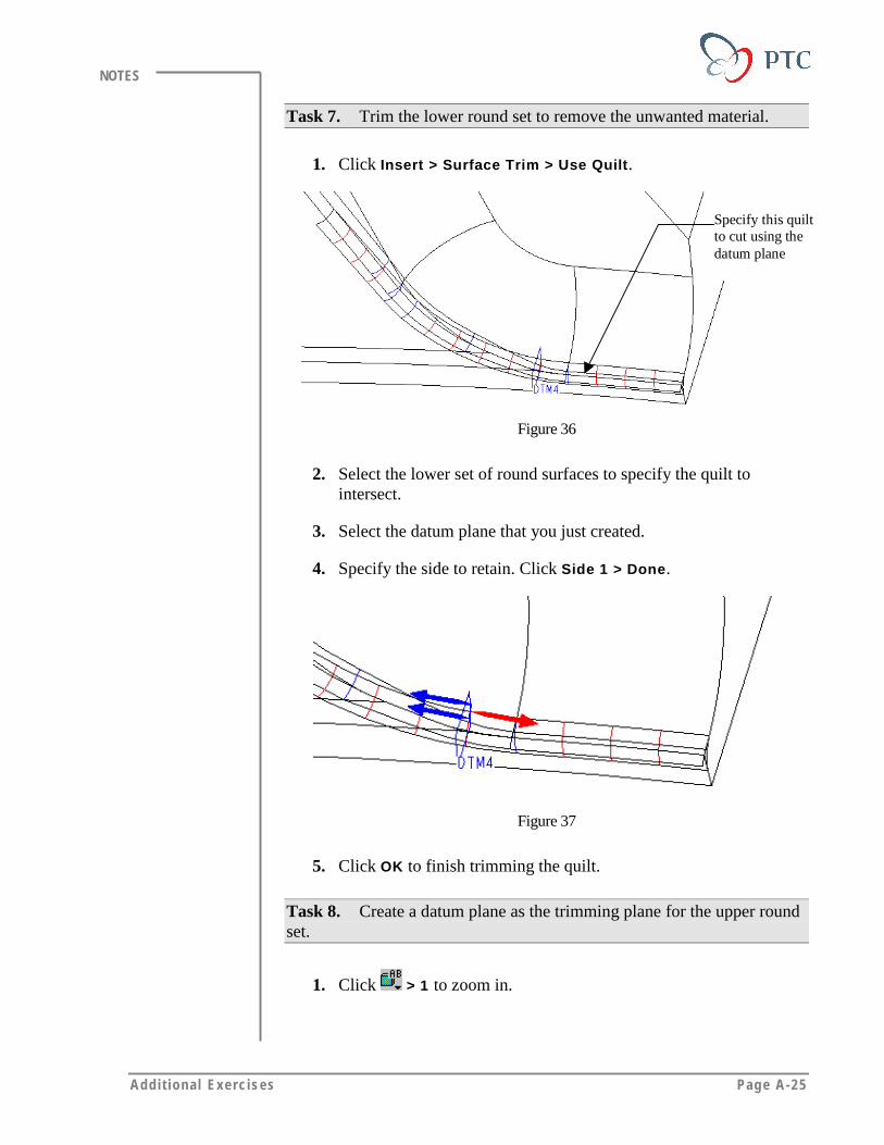
Addi t ional Exerc ises Page A-25
NOTES
Task 7. Trim the lower round set to remove the unwanted material.
1. Click Insert > Surface Trim > Use Quilt.
Specify this quiltto cut using thedatum plane
Figure 36
2. Select the lower set of round surfaces to specify the quilt tointersect.
3. Select the datum plane that you just created.
4. Specify the side to retain. Click Side 1 > Done.
Figure 37
5. Click OK to finish trimming the quilt.
Task 8. Create a datum plane as the trimming plane for the upper roundset.
1. Click > 1 to zoom in.

Page A-26 Des igning w i th Surfaces
NOTES
2. Create a datum point on the upper edge chain to locate the datumplane. Click Insert > Datum > Point > On Curve > Length Ratio.Select the edge, as shown in the following figure, and then clickDone Sel.
Select this location forthe datum point
Figure 38
3. Type [0.25] as the curve length ratio, and then click .
4. Click Done to complete the point.
5. Create a datum plane. Click Insert > Datum > Plane > Through.
6. Select the datum point that you created previously.
7. Click Normal and select the edge, as shown in the followingfigure. Click Done.
Make a datumthrough the datumpoint and normal tothis edge
Figure 39
8. Redefine the datum plane to fit the edge. Click Feature >Redefine and select the datum plane that you just created.
9. Click Attributes > Done > Fit Edge > Done.
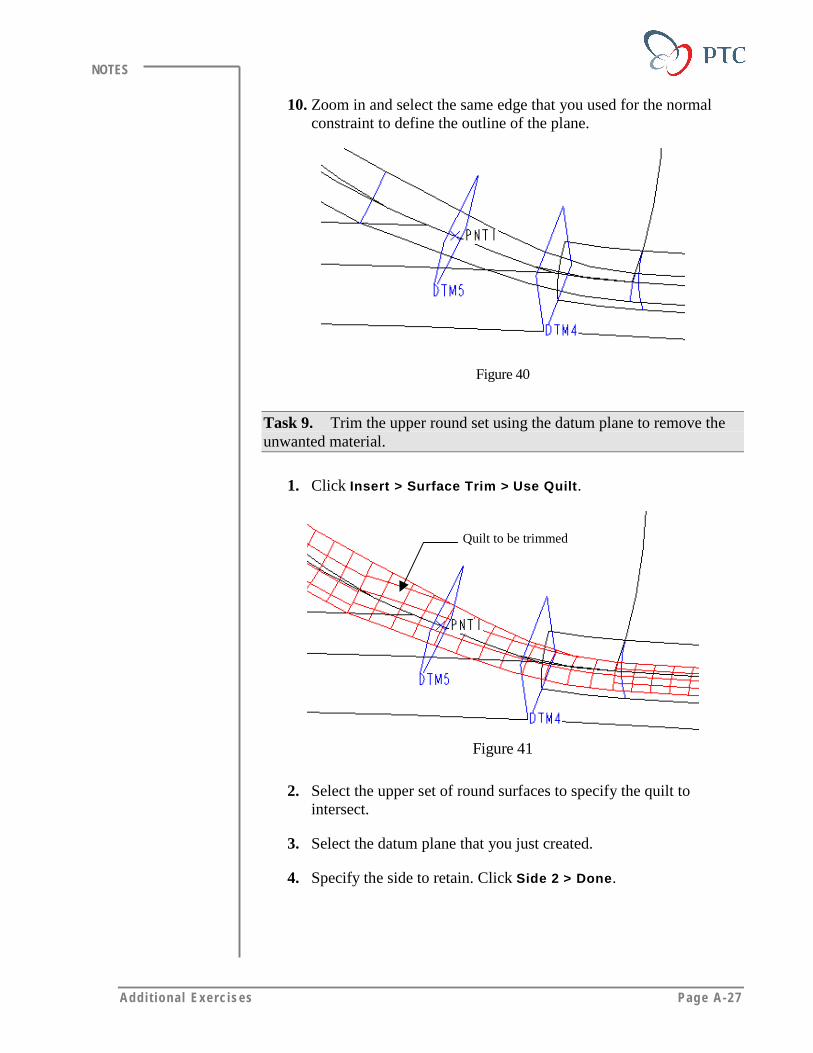
Addi t ional Exerc ises Page A-27
NOTES
10. Zoom in and select the same edge that you used for the normalconstraint to define the outline of the plane.
Figure 40
Task 9. Trim the upper round set using the datum plane to remove theunwanted material.
1. Click Insert > Surface Trim > Use Quilt.
Quilt to be trimmed
Figure 41
2. Select the upper set of round surfaces to specify the quilt tointersect.
3. Select the datum plane that you just created.
4. Specify the side to retain. Click Side 2 > Done.
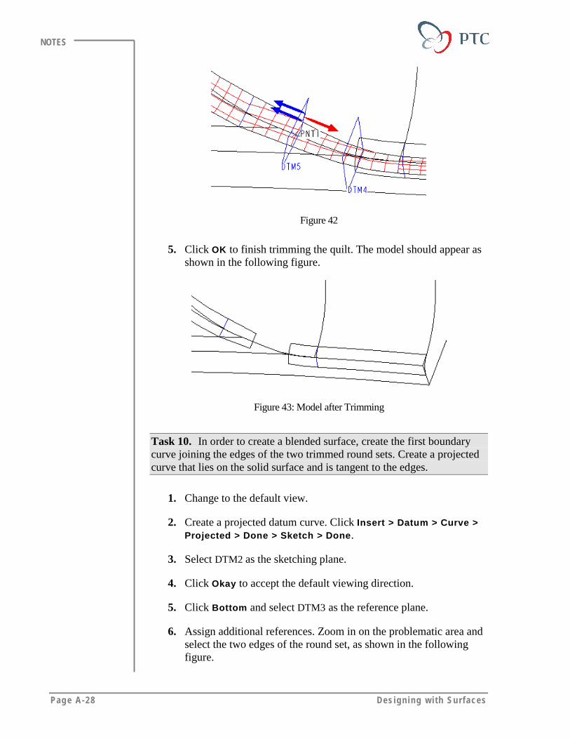
Page A-28 Des igning w i th Surfaces
NOTES
Figure 42
5. Click OK to finish trimming the quilt. The model should appear asshown in the following figure.
Figure 43: Model after Trimming
Task 10. In order to create a blended surface, create the first boundarycurve joining the edges of the two trimmed round sets. Create a projectedcurve that lies on the solid surface and is tangent to the edges.
1. Change to the default view.
2. Create a projected datum curve. Click Insert > Datum > Curve >Projected > Done > Sketch > Done.
3. Select DTM2 as the sketching plane.
4. Click Okay to accept the default viewing direction.
5. Click Bottom and select DTM3 as the reference plane.
6. Assign additional references. Zoom in on the problematic area andselect the two edges of the round set, as shown in the followingfigure.

Addi t ional Exerc ises Page A-29
NOTES
7. Sketch a spline with tangent ends, using the end points to connectthe two surface patches, as shown in the following figure.
Select theseedges as theadditionalreference
Figure 44
8. Add tangency constraint to make the curve tangent to the edges.
Figure 45
9. Click to finish the sketch.
10. Change the view. Click > 1.
11. Specify the surface for projection. Retain the defaults Surface,Include, and Indiv Surf. Select the large round surface, as shownin the following figure.
Surface ontowhich to project
the spline
Figure 46
12. Click Done Sel > Done > Norm to Sket > Done.

Page A-30 Des igning w i th Surfaces
NOTES
Note:
The second option, Norm to Surf, projects the sketch normalto the selected surface.
13. Click OK to finish creating the projected datum curve.
Projected Curve
Figure 47
Task 11. Create another curve to define the second boundary of theblended surface. Create a projected curve that lies on the solid surfacesand that is tangent to the edges of the round set surfaces.
1. Click Insert > Datum > Curve > Projected > Done > Sketch,and Done.
2. Select DTM3 as the sketching plane.
3. Click Okay to accept the default viewing direction.
4. Click Top and select DTM2 as the reference plane.
5. Define the additional Sketcher references. Select two edges, asshown in the following figure.
Select thesetwo edges asadditionalreference
Figure 48
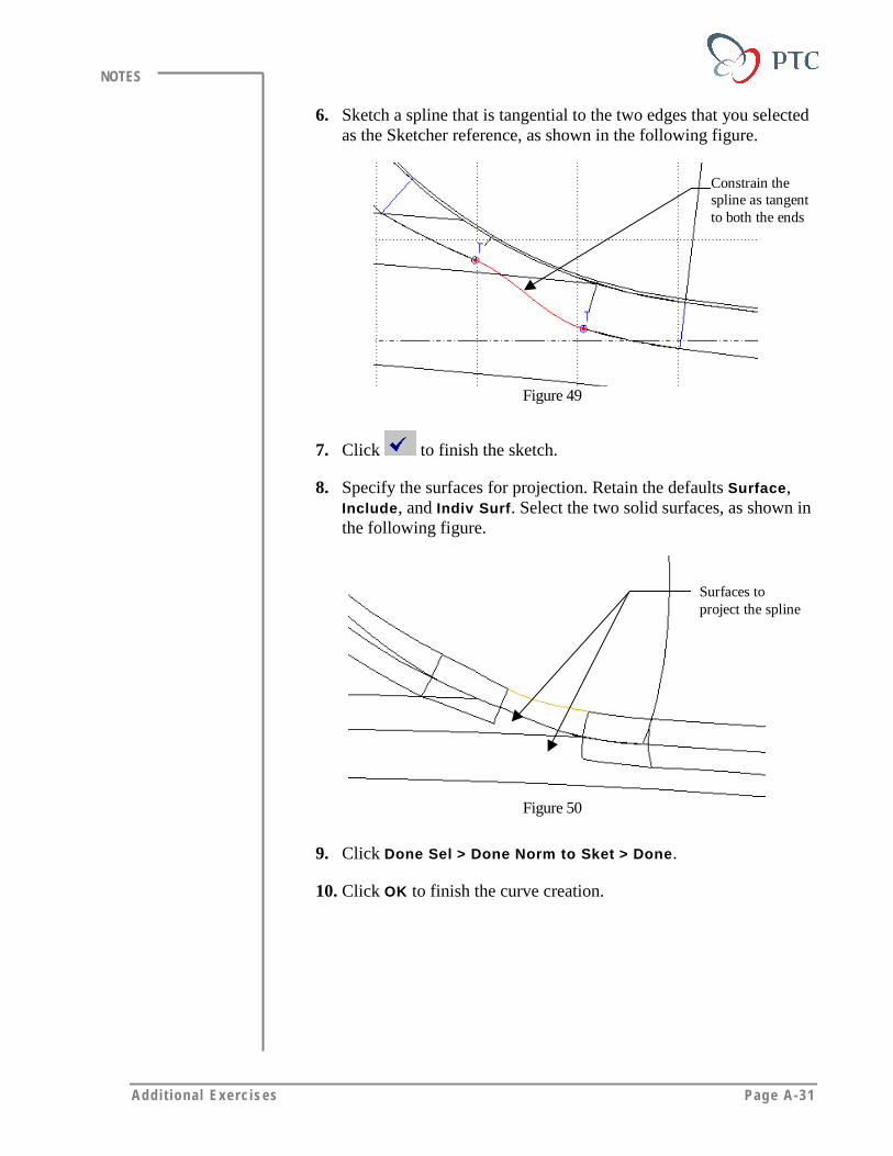
Addi t ional Exerc ises Page A-31
NOTES
6. Sketch a spline that is tangential to the two edges that you selectedas the Sketcher reference, as shown in the following figure.
Constrain thespline as tangentto both the ends
Figure 49
7. Click to finish the sketch.
8. Specify the surfaces for projection. Retain the defaults Surface,Include, and Indiv Surf. Select the two solid surfaces, as shown inthe following figure.
Surfaces toproject the spline
Figure 50
9. Click Done Sel > Done Norm to Sket > Done.
10. Click OK to finish the curve creation.
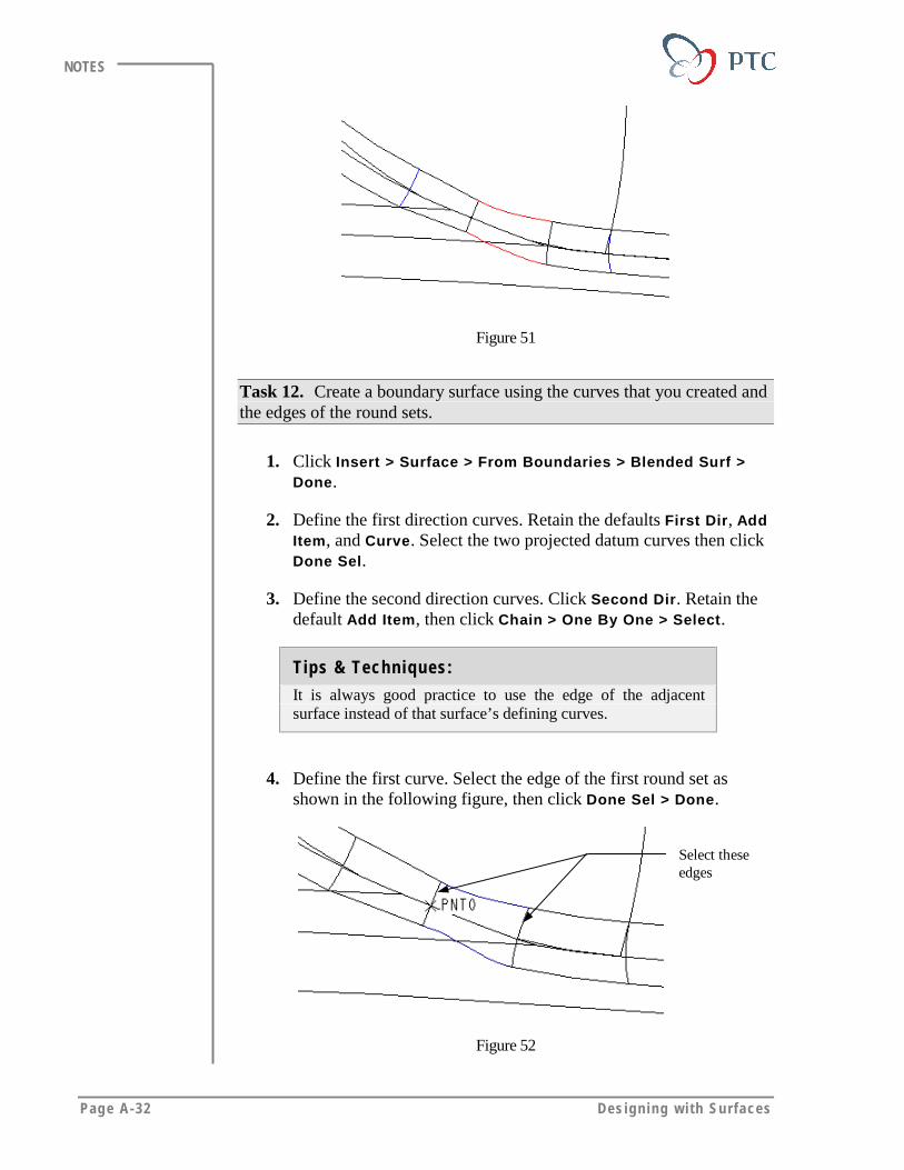
Page A-32 Des igning w i th Surfaces
NOTES
Figure 51
Task 12. Create a boundary surface using the curves that you created andthe edges of the round sets.
1. Click Insert > Surface > From Boundaries > Blended Surf >Done.
2. Define the first direction curves. Retain the defaults First Dir, AddItem, and Curve. Select the two projected datum curves then clickDone Sel.
3. Define the second direction curves. Click Second Dir. Retain thedefault Add Item, then click Chain > One By One > Select.
Tips & Techniques:
It is always good practice to use the edge of the adjacentsurface instead of that surface’s defining curves.
4. Define the first curve. Select the edge of the first round set asshown in the following figure, then click Done Sel > Done.
Select theseedges
Figure 52
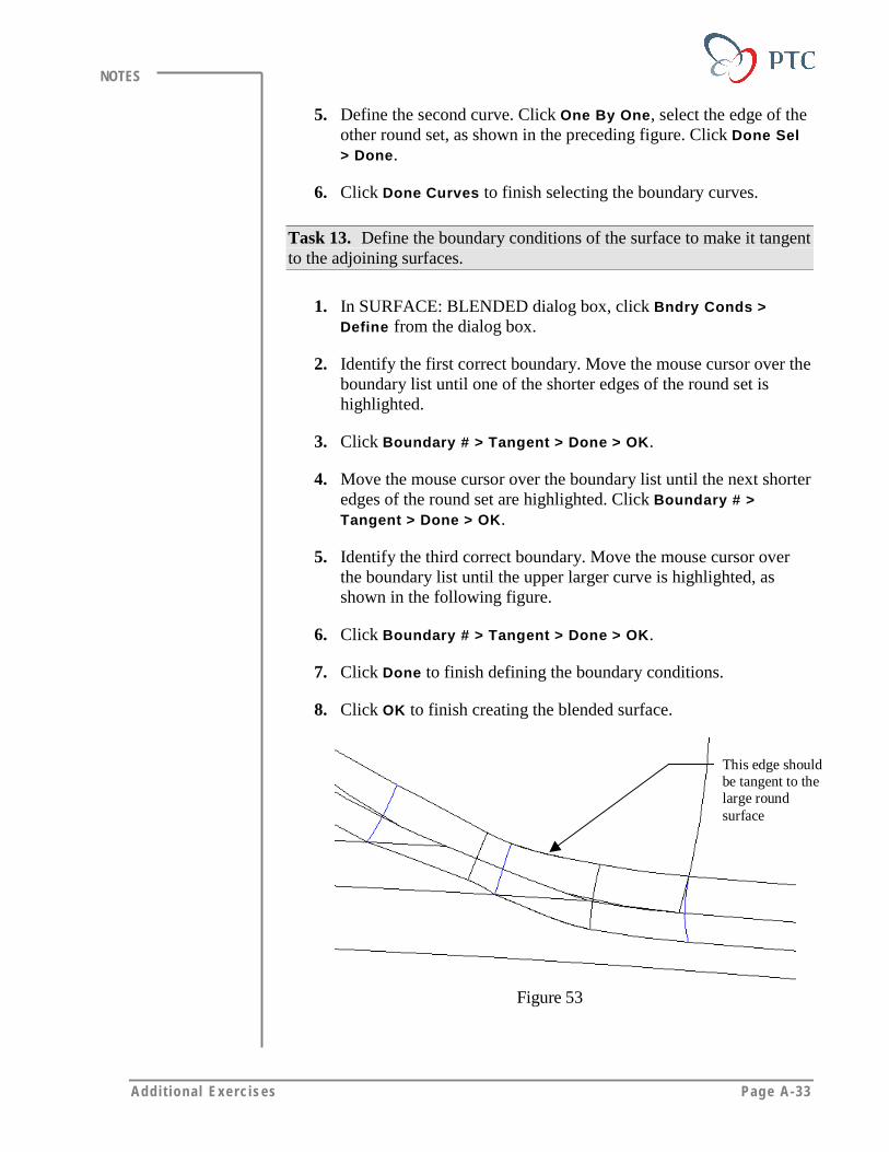
Addi t ional Exerc ises Page A-33
NOTES
5. Define the second curve. Click One By One, select the edge of theother round set, as shown in the preceding figure. Click Done Sel> Done.
6. Click Done Curves to finish selecting the boundary curves.
Task 13. Define the boundary conditions of the surface to make it tangentto the adjoining surfaces.
1. In SURFACE: BLENDED dialog box, click Bndry Conds >Define from the dialog box.
2. Identify the first correct boundary. Move the mouse cursor over theboundary list until one of the shorter edges of the round set ishighlighted.
3. Click Boundary # > Tangent > Done > OK.
4. Move the mouse cursor over the boundary list until the next shorteredges of the round set are highlighted. Click Boundary # >Tangent > Done > OK.
5. Identify the third correct boundary. Move the mouse cursor overthe boundary list until the upper larger curve is highlighted, asshown in the following figure.
6. Click Boundary # > Tangent > Done > OK.
7. Click Done to finish defining the boundary conditions.
8. Click OK to finish creating the blended surface.
This edge shouldbe tangent to thelarge roundsurface
Figure 53
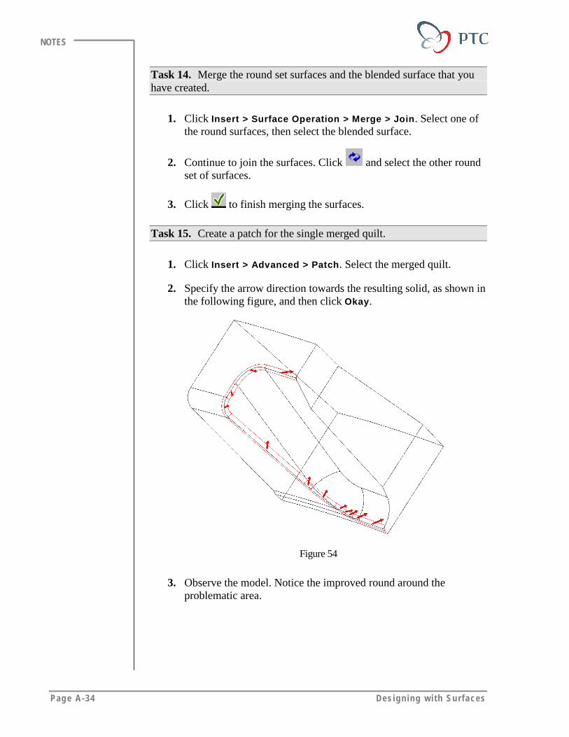
Page A-34 Des igning w i th Surfaces
NOTES
Task 14. Merge the round set surfaces and the blended surface that youhave created.
1. Click Insert > Surface Operation > Merge > Join. Select one ofthe round surfaces, then select the blended surface.
2. Continue to join the surfaces. Click and select the other roundset of surfaces.
3. Click to finish merging the surfaces.
Task 15. Create a patch for the single merged quilt.
1. Click Insert > Advanced > Patch. Select the merged quilt.
2. Specify the arrow direction towards the resulting solid, as shown inthe following figure, and then click Okay.
Figure 54
3. Observe the model. Notice the improved round around theproblematic area.

Addi t ional Exerc ises Page A-35
NOTES
Figure 55: The Improved Round
4. Save the model and erase it from memory.


Page B-1
Appendix
Using PTC HelpYou can use PTC Help to quickly search for Pro/ENGINEER
information. PTC Help includes quick references and detailed
information on selected topics.
Objectives
After completing this module, you will be able to:
• Start PTC Help.
• Search for specific information about Pro/ENGINEER.
• Obtain context-sensitive help while performing a task.

Page B-2 Append ix B
NOTES
PTC HELP OVERVIEWPTC Help is a fully functional help system that is integrated intoPro/ENGINEER.
PTC Help FeaturesPTC Help offers:
• A new help system with a table of contents, an index, and searchingcapability
• Context-sensitive help, allowing access to PTC Help with a click ofthe mouse
• Online Tutorials focussed on teaching different aspects of the software
• Expanded help topics available as special dialog boxes
Please visit the PTC Technical Support Online Knowledge Database,which features thousands of Suggested Techniques. For moreinformation, see the Technical Support Appendix.
USING THE Pro/ENGINEER HELP SYSTEM
Launching Help: Four MethodsThere are four procedures for launching the help system.
1. From the Main Menu
This is the standard way of accessing the full-blown help system completewith contents, index, and search capabilities. Depending on your systemspeed, it may take a few seconds to launch the entire help system.
Click Help > Contents and Index from the main menu as shown in thefollowing figure.
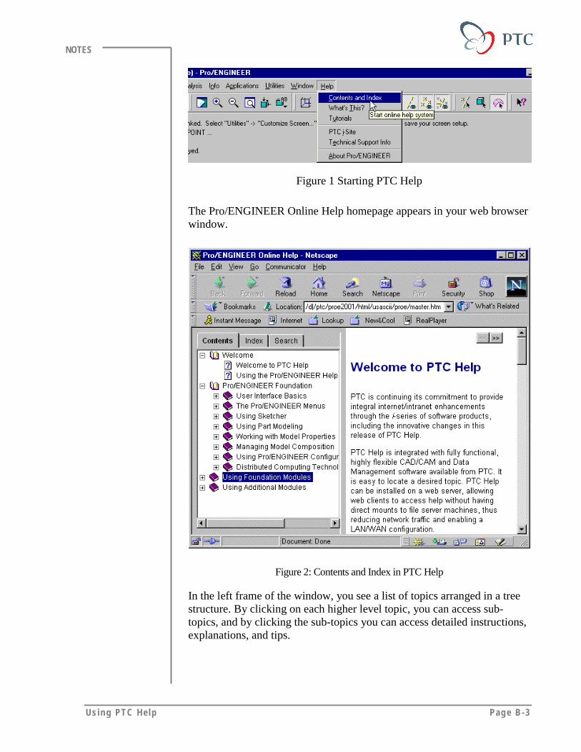
Using PTC Help Page B-3
NOTES
Figure 1 Starting PTC Help
The Pro/ENGINEER Online Help homepage appears in your web browserwindow.
Figure 2: Contents and Index in PTC Help
In the left frame of the window, you see a list of topics arranged in a treestructure. By clicking on each higher level topic, you can access sub-topics, and by clicking the sub-topics you can access detailed instructions,explanations, and tips.

Page B-4 Append ix B
NOTES
2. Through Context-Sensitive Help
1. Click on the right end of the main toolbar.
2. Click on any icon or any part of the Pro/ENGINEER main windowabout which you want an explanation.
3. A browser window opens that explains the topic.
4. In the following example, clicking on the model tree icon in thetoolbar launched a browser window that explained the iconfunctionality.
Figure 3: Context-Sensitive Help
5. In addition, you will also notice at the lower left there is a “SeeAlso” link which on clicking provides a list of related topics thatmay be of immediate interest.

Using PTC Help Page B-5
NOTES
6. You may click on any topic you want to read additionally.
Figure 4: The ‘See Also’ List of Topics
3. Through Pro/ENGINEER Menu Manager
1. Click on the right end of the main Pro/ENGINEER toolbar.
2. Click any menu command from the menu manager.
3. A TOPIC ROUTER browser window opens with a list of topic linksthat explain the menu command.
4. Click the topic you want to read.
5. In the following example, clicking on X-Section in the menumanager launched the TOPIC ROUTER browser window with a listof two useful topics.
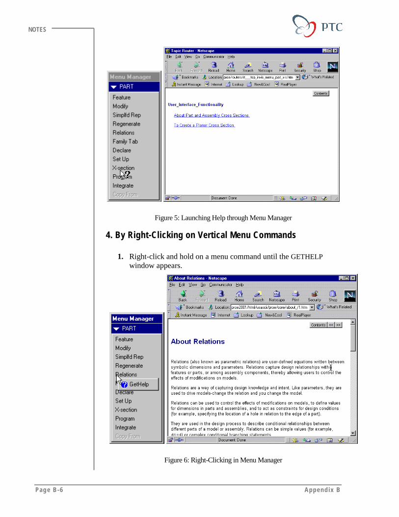
Page B-6 Append ix B
NOTES
Figure 5: Launching Help through Menu Manager
4. By Right-Clicking on Vertical Menu Commands
1. Right-click and hold on a menu command until the GETHELPwindow appears.
Figure 6: Right-Clicking in Menu Manager
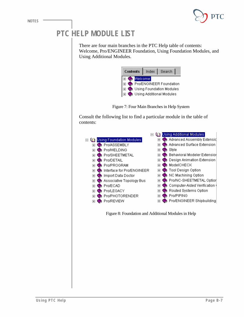
Using PTC Help Page B-7
NOTES
PTC HELP MODULE LISTThere are four main branches in the PTC Help table of contents:Welcome, Pro/ENGINEER Foundation, Using Foundation Modules, andUsing Additional Modules.
Figure 7: Four Main Branches in Help System
Consult the following list to find a particular module in the table ofcontents:
Figure 8: Foundation and Additional Modules in Help