Embed Size (px)
Citation preview
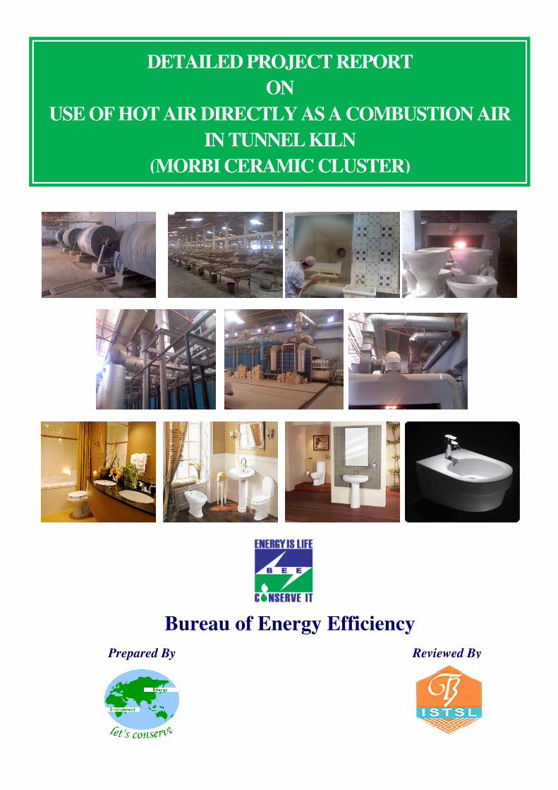
DETAILED PROJECT REPORT
ON
USE OF HOT AIR DIRECTLY AS A COMBUSTION AIR
IN TUNNEL KILN
(MORBI CERAMIC CLUSTER)
Bureau of Energy Efficiency
Prepared By
Reviewed By
USE OF
HOT AIR DIRECTLY
AS A CUMBUSTION AIR IN TUNNEL KILN
MORBI CERAMIC CLUSTER
BEE, 2010
Detailed Project Report on Use of Hot Air Directly As a Combustion Air in
Tunnel Kiln
Ceramic SME Cluster, Morbi, Gujarat (India)
New Delhi: Bureau of Energy Efficiency;
Detail Project Report No.: MRV/CRM/HCT/03
For more information
Bureau of Energy Efficiency (BEE)
(Ministry of Power, Government of India)
4th Floor, Sewa Bhawan
R. K. Puram, New Delhi – 110066
Telephone +91-11-26179699
Fax +91-11-26178352
Websites: www.bee-india.nic.in
Email: [email protected]/ [email protected]
Acknowledgement
We sincerely appreciate the efforts of industry, energy auditors, equipment manufacturers,
technology providers, consultants and other experts in the area of energy conservation for
joining hands with Bureau of Energy Efficiency (BEE), Ministry of Power, Government of India
for preparing the Detailed Project Report (DPR) under BEE SME Program in SMEs clusters.
We appreciate the support of suppliers/vendors for providing the adoptable energy efficient
equipments/technical details to the SMEs.
We have received very encouraging feedback for the BEE SME Program in various SME
Clusters. Therefore, it was decided to bring out the DPR for the benefits of SMEs. We
sincerely thank the officials of BEE, Executing Agencies and ISTSL for all the support and
cooperation extended for preparation of the DPR. We gracefully acknowledge the diligent
efforts and commitments of all those who have contributed in preparation of the DPR.
ii
Contents
List of Annexure iv
List of Tables v
List of Figures vi
List of Abbreviation vi
Executive summary vii
About BEE’S SME program viii
1 INTRODUCTION ................................................................................................................ 1
1.1 Brief Introduction about Cluster....................................................................................... 1
1.2 Energy performance in existing situation ........................................................................ 4
1.2.1 Average production ..................................................................................................... 4
1.2.2 Fuel consumption ........................................................................................................ 5
1.2.3 Specific Energy Consumption ..................................................................................... 5
1.3 Proposed technology/equipment..................................................................................... 6
1.3.1 Description of technology/ equipment.......................................................................... 6
1.3.2 Role in process ........................................................................................................... 6
1.4 Benchmarking for existing specific energy consumption ................................................. 6
1.4.1 Energy audit methodology ........................................................................................... 6
1.4.2 Design and operating parameters specification ........................................................... 8
1.4.3 Operating efficiency analysis ....................................................................................... 8
1.5 Barriers in adoption of proposed technology/equipment ................................................. 8
1.5.1 Technological Barrier .................................................................................................. 8
1.5.2 Financial Barrier .......................................................................................................... 8
1.5.3 Skilled manpower ........................................................................................................ 9
1.5.4 Other barrier (If any) .................................................................................................... 9
2 PROPOSED TECHNOLOGY ........................................................................................... 10
2.1 Detailed description of technology ................................................................................ 10
iii
2.1.1 Description of technology .......................................................................................... 10
2.1.2 Equipment specification ............................................................................................ 10
2.1.3 Suitability over existing equipment ............................................................................ 10
2.1.4 Superiority over existing equipment .......................................................................... 11
2.1.5 Availability of equipment............................................................................................ 11
2.1.6 Source of equipment ................................................................................................. 11
2.1.7 Technical specification of equipment ......................................................................... 11
2.1.8 Terms and conditions in sales of equipment.............................................................. 11
2.1.9 Process down time during implementation ................................................................ 11
2.2 Life cycle assessment and risks analysis .................................................................. 11
2.3 Suitable Unit for Implementation of proposed technology .......................................... 11
3 ECONOMIC BENEFITS FROM PROPOSED EQUIPMENT ...................................... 12
3.1 Technical benefit .......................................................................................................... 12
3.1.1 Fuel saving................................................................................................................ 12
3.1.2 Electricity saving ....................................................................................................... 12
3.1.3 Improvement in product quality ................................................................................. 12
3.1.4 Increase in production ............................................................................................... 12
3.1.5 Reduction in raw material .......................................................................................... 12
3.1.6 Reduction in other losses .......................................................................................... 12
3.2 Monetary benefits ......................................................................................................... 12
3.3 Social benefits .............................................................................................................. 13
3.3.1 Improvement in working environment in the plant...................................................... 13
3.3.2 Improvement in workers skill ..................................................................................... 13
3.4 Environmental benefits ................................................................................................. 13
3.4.1 Reduction in effluent generation ................................................................................ 13
3.4.2 Reduction in GHG emission ...................................................................................... 13
3.4.3 Reduction in other emissions like SOX ...................................................................... 13
iv
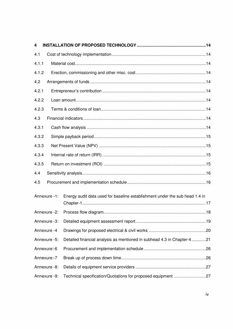
4 INSTALLATION OF PROPOSED TECHNOLOGY .......................................................... 14
4.1 Cost of technology implementation ............................................................................... 14
4.1.1 Material cost .............................................................................................................. 14
4.1.2 Erection, commissioning and other misc. cost ........................................................... 14
4.2 Arrangements of funds ................................................................................................. 14
4.2.1 Entrepreneur’s contribution ....................................................................................... 14
4.2.2 Loan amount. ............................................................................................................ 14
4.2.3 Terms & conditions of loan ........................................................................................ 14
4.3 Financial indicators ....................................................................................................... 14
4.3.1 Cash flow analysis .................................................................................................... 14
4.3.2 Simple payback period .............................................................................................. 15
4.3.3 Net Present Value (NPV) .......................................................................................... 15
4.3.4 Internal rate of return (IRR) ....................................................................................... 15
4.3.5 Return on investment (ROI) ...................................................................................... 15
4.4 Sensitivity analysis........................................................................................................ 16
4.5 Procurement and implementation schedule .................................................................. 16
Annexure -1: Energy audit data used for baseline establishment under the sub head 1.4 in
Chapter-1........................................................................................................ 17
Annexure -2: Process flow diagram...................................................................................... 18
Annexure -3: Detailed equipment assessment report ........................................................... 19
Annexure -4 Drawings for proposed electrical & civil works ................................................ 20
Annexure -5: Detailed financial analysis as mentioned in subhead 4.3 in Chapter-4 ............ 21
Annexure:-6 Procurement and implementation schedule .................................................... 26
Annexure:-7 Break up of process down time. ...................................................................... 26
Annexure -8: Details of equipment service providers ........................................................... 27
Annexure -9: Technical specification/Quotations for proposed equipment ........................... 27
v
List of Table
Table 1.1 Details of annual energy consumption scenario at Morbi ceramic cluster.......... 1
Table 1.2 Production wise unit breakups .......................................................................... 2
Table 1.3 Product manufactured....................................................................................... 2
Table 1.4 Annual productions from a typical unit .............................................................. 4
Table 1.5 Annual energy consumption.............................................................................. 5
Table 1.6 Specific energy consumption of different ceramic unit....................................... 5
Table 1.7 Fuel Consumption in tunnel kiln for different plant capacities ............................ 8
Table 3.1 Energy and monetary benefit due to project implementation ........................... 13
Table 4.1 Details of proposed equipment installation cost .............................................. 14
Table 4.2 Financial indicators of proposed technology ................................................... 15
Table 4.3 Sensitivity analysis .......................................................................................... 16
Table 4.4 Procurement and implementation schedule .................................................... 16
vi
List of Figure
Figure 1.1 Process flow diagram of sanitary ware .............................................................. 3
Figure 1.2 Energy Audit methodologies ............................................................................. 7
List of Abbreviation
BEE Bureau of Energy Efficiency
SME Small and Medium Enterprises
DPR Detailed Project Report
GHG Green House Gases
CDM Clean Development Mechanism
DSCR Debt Service Coverage Ratio
NPV Net Present Value
IRR Internal Rate of Return
ROI Return on Investment
WHR Waste Heat Recovery
SCM Standard Cubic Meter
MT Metric Tonne
SIDBI Small Industrial Development Bank of India
vii
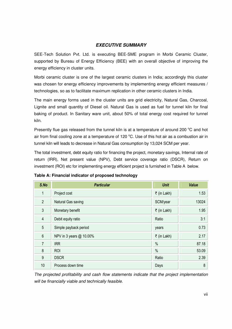
EXECUTIVE SUMMARY
SEE-Tech Solution Pvt. Ltd. is executing BEE-SME program in Morbi Ceramic Cluster,
supported by Bureau of Energy Efficiency (BEE) with an overall objective of improving the
energy efficiency in cluster units.
Morbi ceramic cluster is one of the largest ceramic clusters in India; accordingly this cluster
was chosen for energy efficiency improvements by implementing energy efficient measures /
technologies, so as to facilitate maximum replication in other ceramic clusters in India.
The main energy forms used in the cluster units are grid electricity, Natural Gas, Charcoal,
Lignite and small quantity of Diesel oil. Natural Gas is used as fuel for tunnel kiln for final
baking of product. In Sanitary ware unit, about 50% of total energy cost required for tunnel
kiln.
Presently flue gas released from the tunnel kiln is at a temperature of around 200 oC and hot
air from final cooling zone at a temperature of 120 oC. Use of this hot air as a combustion air in
tunnel kiln will leads to decrease in Natural Gas consumption by 13,024 SCM per year.
The total investment, debt equity ratio for financing the project, monetary savings, Internal rate of
return (IRR), Net present value (NPV), Debt service coverage ratio (DSCR), Return on
investment (ROI) etc for implementing energy efficient project is furnished in Table A below.
Table A: Financial indicator of proposed technology
S.No Particular Unit Value
1 Project cost ` (in Lakh) 1.53
2 Natural Gas saving SCM/year 13024
3 Monetary benefit ` (in Lakh) 1.95
4 Debit equity ratio Ratio 3:1
5 Simple payback period years 0.73
6 NPV in 3 years @ 10.00% ` (in Lakh) 2.17
7 IRR % 87.18
8 ROI % 53.09
9 DSCR Ratio 2.39
10 Process down time Days 8
The projected profitability and cash flow statements indicate that the project implementation
will be financially viable and technically feasible.
viii
ABOUT BEE’S SME PROGRAM
Bureau of Energy Efficiency (BEE) is implementing a BEE-SME Programme to improve the
energy performance in 25 selected SMEs clusters. Morbi Ceramic Cluster is one of them. The
BEE’s SME Programme intends to enhance the energy efficiency awareness by
funding/subsidizing need based studies in SME clusters and giving energy conservation
recommendations. For addressing the specific problems of these SMEs and enhancing
energy efficiency in the clusters, BEE will be focusing on energy efficiency, energy
conservation and technology up gradation through studies and pilot projects in these SMEs
clusters.
Major activities in the BEE -SME program are furnished below:
Energy use and technology audit
The energy use technology studies would provide information on technology status, best
operating practices, gaps in skills and knowledge on energy conservation opportunities,
energy saving potential and new energy efficient technologies, etc for each of the sub sector
in SMEs.
Capacity building of stake holders in cluster on energy efficiency
In most of the cases SME entrepreneurs are dependent on the locally available technologies,
service providers for various reasons. To address this issue BEE has also undertaken
capacity building of local service providers and entrepreneurs/ managers of SMEs on energy
efficiency improvement in their units as well as clusters. The local service providers will be
trained in order to be able to provide the local services in setting of energy efficiency projects
in the clusters
Implementation of energy efficiency measures
To implement the technology up gradation projects in clusters, BEE has proposed to prepare
the technology based detailed project reports (DPRs) for a minimum of five technologies in
three capacities for each technology.
Facilitation of innovative financing mechanisms for implementation of energy
efficiency projects
The objective of this activity is to facilitate the uptake of energy efficiency measures through
innovative financing mechanisms without creating market distortion
Use of Hot Air Directly As a Combustion Air In Tunnel Kiln
Page 1 of 28
1 INTRODUCTION
1.1 Brief Introduction about Cluster
Morbi SME Cluster is one of the largest ceramic clusters in India and mainly famous for
manufacturing of ceramic tiles. Over 70% of total ceramic tiles product comes from Morbi
cluster. The nearest airport is at Rajkot, which is 67 KM from Morbi by road. Morbi could also
be reached from Ahmadabad by Railway as well as by road which is about 184 KM.
There are approximately 479 ceramic units in this cluster which are engaged in manufacturing
of Wall Tiles, Vitrified Tiles, Floor Tiles, Sanitary wares, Roofing Tiles and others product.
There are around 50 more ceramic units coming up in Morbi.
Majority of the cluster units are of integrated type, where the raw material is processed in-
house to the final product. Majority of the units in the cluster are dependent on local / run of the
mill technologies which is supplied by local service provider. Table 1.1 shows the total energy
consumption scenario at Morbi cluster.
Table 1.1 Details of annual energy consumption scenario at Morbi ceramic cluster
Energy usages pattern
Average monthly electricity consumption in ceramic industry ranges from 1 lakh to 2 lakh kWh
depending on the size of the industry. In thermal energy, solid fuel such as lignite, charcoal,
Indonesian coal, briquette, etc are used in spray dryer and Natural Gas is used in kiln in all
industries except few of them. Solid fuel consumption in spray dryer ranges from 80 to 160
kg/MT of production. Natural Gas consumption in kiln varies from 1.01 to 1.4 SCM/m2 of tiles
produced.
Classification of Units
The ceramic units can be categorized into four types based on product manufacture
S. No Type of Fuel Unit Value % contribution
1 Electricity GWh /year 1,200 8.23
2 Natural Gas SCM/year 660,000,000 46.32
3 Charcoal Tonne/year 165,000 8.55
4 Lignite Tonne/year 1,320,000 36.84
5 Diesel Liter/year 800,000 0.06

Use of Hot Air Directly As a Combustion Air In Tunnel Kiln
Page 2 of 28
• Floor Tiles unit
• Vitrified Tiles unit
• Sanitary Wares unit
Production wise unit breakup
Morbi ceramic cluster can be breakup into three categories viz. small, medium and large scale
unit. Table 1.2 shows that production wise breakup of Morbi cluster.
Table 1.2 Production wise unit breakups
Products Manufactured
Different types of products manufactured in Morbi SME cluster are as shown in Table 1.3
below
Table 1.3 Product manufactured
1 In case of sanitary wares, production is measured in terms of MT.
Type of product No. of Units. Production (m2/day or MT1/day)
Scale of Unit
Small Medium Large Total Small Medium Large Total
Wall Tiles 43 100 35 178 2,500 3,500 7,500 13,500
Floor Tiles 8 38 6 52 3,000 4,000 7,000 14,000
Vitrified Tiles 22 4 26 5,760 11,520 17,280
Sanitary Wares 10 24 9 43 4 8 14 26
S. No Type of Product % share Units
1 Wall Tiles 37 178
2 Vitrified Tiles 8 36
3 Floor Tiles 11 52
4 Sanitary Wares 9 43
5 Spray Dryer Mud Manufacturing Units 8 40
6 Roofing Tiles (seasonal operation) 25 120
7 Third Firing Manufacturing (Producing pictures on tiles) 37 10
Total 479
Use of Hot Air Directly As a Combustion Air In Tunnel Kiln
Page 3 of 28
Raw Material (Powder)
Slip Section
(Ball Mill)
Agitator Tank
Mould
Finishing and Drying
Glazing Section
Kiln
Finishing Product
Electricity
Electricity
Electricity
Electricity
Electricity
Water
Compressed
Air
Fuel such as
NG
Compressed
Air
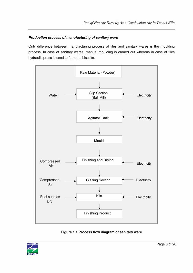
Production process of manufacturing of sanitary ware
Only difference between manufacturing process of tiles and sanitary wares is the moulding
process. In case of sanitary wares, manual moulding is carried out whereas in case of tiles
hydraulic press is used to form the biscuits.
Figure 1.1 Process flow diagram of sanitary ware
Use of Hot Air Directly As a Combustion Air In Tunnel Kiln
Page 4 of 28
Wet Grinding
Raw materials such as clay, feldspar, quartz, calcite etc. are mixed with water in a proper
proportion and are grinded in a ball mill to make a homogeneous mixture. Ball Mill is a batch
type of process. After completion of one batch of ball mill, slurry is taken in to the underground
tanks fitted with agitator motor in each tank to maintain the uniformity of mixture.
Moulding
The slip (slurry) is poured into the moulds by a hand held hose. The slip is pumped through a
hydraulic pump into the mould.
Drying
The cast wares are then dried in natural environment with the help of ceiling fans.
Glazing
The dried wares are then glazed in spray glazing booths, where compressed air is used for
spray glazing.
Firing
The glazed wares are then fired in the kilns up to a temperature of 1200 oC where the Natural
Gas is used as a fuel. The output from the kiln is inspected before packaging and dispatch.
1.2 Energy performance in existing situation
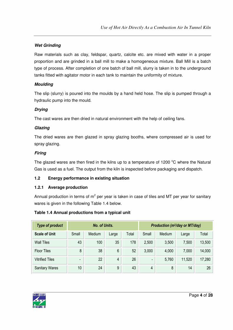
1.2.1 Average production
Annual production in terms of m2 per year is taken in case of tiles and MT per year for sanitary
wares is given in the following Table 1.4 below.
Table 1.4 Annual productions from a typical unit
Type of product No. of Units. Production (m2/day or MT/day)
Scale of Unit Small Medium Large Total Small Medium Large Total
Wall Tiles 43 100 35 178 2,500 3,500 7,500 13,500
Floor Tiles 8 38 6 52 3,000 4,000 7,000 14,000
Vitrified Tiles - 22 4 26 - 5,760 11,520 17,280
Sanitary Wares 10 24 9 43 4 8 14 26
Use of Hot Air Directly As a Combustion Air In Tunnel Kiln
Page 5 of 28
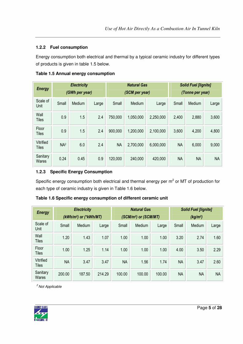
1.2.2 Fuel consumption
Energy consumption both electrical and thermal by a typical ceramic industry for different types
of products is given in table 1.5 below.
Table 1.5 Annual energy consumption
1.2.3 Specific Energy Consumption
Specific energy consumption both electrical and thermal energy per m2 or MT of production for
each type of ceramic industry is given in Table 1.6 below.
Table 1.6 Specific energy consumption of different ceramic unit
2 Not Applicable
Energy Electricity
(GWh per year)
Natural Gas
(SCM per year)
Solid Fuel [lignite]
(Tonne per year)
Scale of Unit
Small Medium Large Small Medium Large Small Medium Large
Wall Tiles
0.9 1.5 2.4 750,000 1,050,000 2,250,000 2,400 2,880 3,600
Floor Tiles
0.9 1.5 2.4 900,000 1,200,000 2,100,000 3,600 4,200 4,800
Vitrified Tiles
NA2 6.0 2.4 NA 2,700,000 6,000,000 NA 6,000 9,000
Sanitary Wares
0.24 0.45 0.9 120,000 240,000 420,000 NA NA NA
Energy Electricity
(kWh/m2) or (*kWh/MT)
Natural Gas
(SCM/m2) or (SCM/MT)
Solid Fuel [lignite]
(kg/m2)
Scale of Unit
Small Medium Large Small Medium Large Small Medium Large
Wall Tiles
1.20 1.43 1.07 1.00 1.00 1.00 3.20 2.74 1.60
Floor Tiles
1.00 1.25 1.14 1.00 1.00 1.00 4.00 3.50 2.29
Vitrified Tiles
NA 3.47 3.47 NA 1.56 1.74 NA 3.47 2.60
Sanitary Wares
200.00 187.50 214.29 100.00 100.00 100.00 NA NA NA
Use of Hot Air Directly As a Combustion Air In Tunnel Kiln
Page 6 of 28
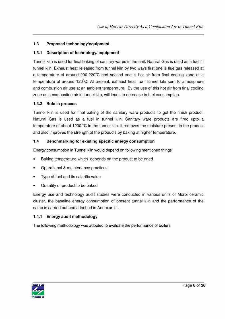
1.3 Proposed technology/equipment
1.3.1 Description of technology/ equipment
Tunnel kiln is used for final baking of sanitary wares in the unit. Natural Gas is used as a fuel in
tunnel kiln. Exhaust heat released from tunnel kiln by two ways first one is flue gas released at
a temperature of around 200-2200C and second one is hot air from final cooling zone at a
temperature of around 1200C. At present, exhaust heat from tunnel kiln sent to atmosphere
and combustion air use at an ambient temperature. By the use of this hot air from final cooling
zone as a combustion air in tunnel kiln, will leads to decrease in fuel consumption.
1.3.2 Role in process
Tunnel kiln is used for final baking of the sanitary ware products to get the finish product.
Natural Gas is used as a fuel in tunnel kiln. Sanitary ware products are fired upto a
temperature of about 1200 oC in the tunnel kiln. It removes the moisture present in the product
and also improves the strength of the products by baking at higher temperature.
1.4 Benchmarking for existing specific energy consumption
Energy consumption in Tunnel kiln would depend on following mentioned things
• Baking temperature which depends on the product to be dried
• Operational & maintenance practices
• Type of fuel and its calorific value
• Quantity of product to be baked
Energy use and technology audit studies were conducted in various units of Morbi ceramic
cluster, the baseline energy consumption of present tunnel kiln and the performance of the
same is carried out and attached in Annexure 1.
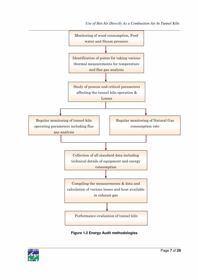
1.4.1 Energy audit methodology
The following methodology was adopted to evaluate the performance of boilers
Use of Hot Air Directly As a Combustion Air In Tunnel Kiln
Page 7 of 28
Monitoring of wood consumption, Feed
water and Steam pressure
Identification of points for taking various
thermal measurements for temperature
and flue gas analysis
Study of process and critical parameters
affecting the tunnel kiln operation &
Losses
Regular monitoring of tunnel kiln
operating parameters including flue
gas analysis
Regular monitoring of Natural Gas
consumption rate
Collection of all standard data including
technical details of equipment and energy
consumption
Compiling the measurements & data and
calculation of various losses and heat available
in exhaust gas
Performance evaluation of tunnel kiln
Figure 1.2 Energy Audit methodologies
Use of Hot Air Directly As a Combustion Air In Tunnel Kiln
Page 8 of 28
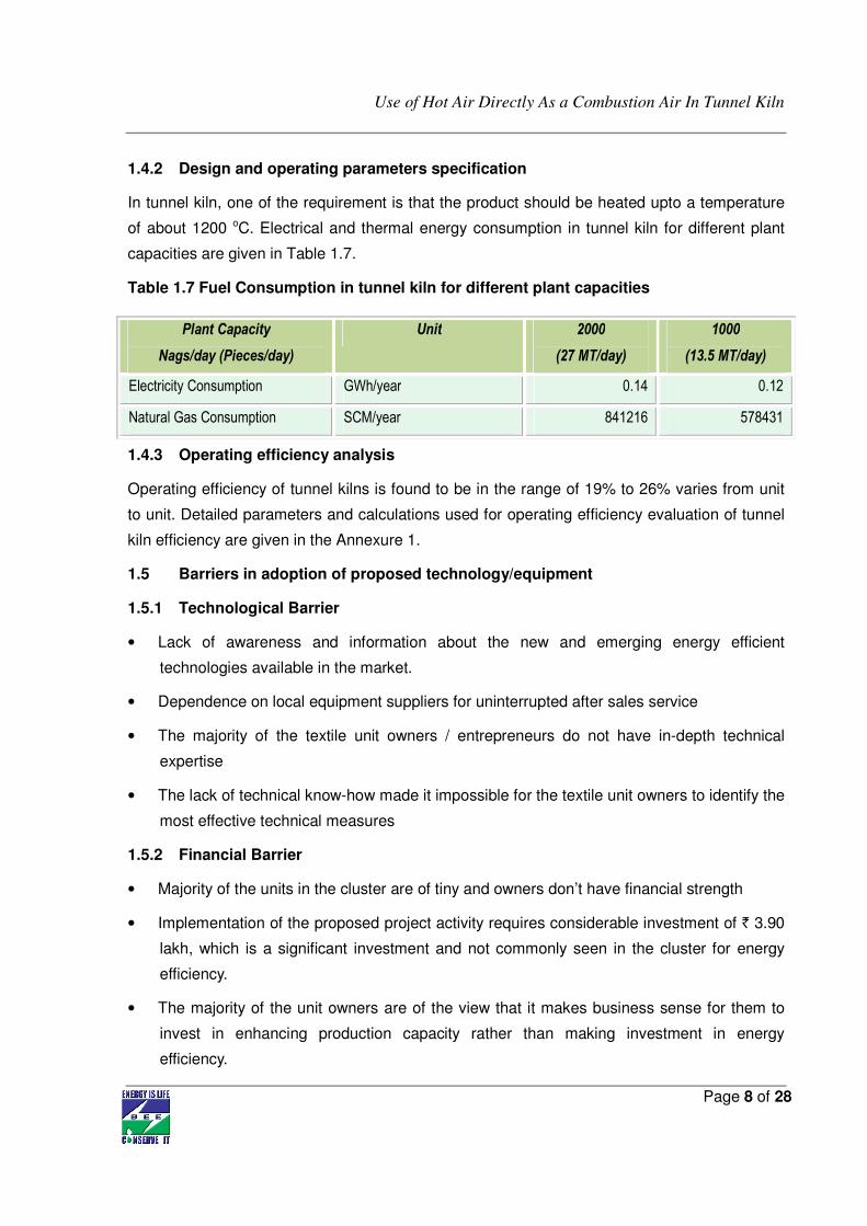
1.4.2 Design and operating parameters specification
In tunnel kiln, one of the requirement is that the product should be heated upto a temperature
of about 1200 oC. Electrical and thermal energy consumption in tunnel kiln for different plant
capacities are given in Table 1.7.
Table 1.7 Fuel Consumption in tunnel kiln for different plant capacities
1.4.3 Operating efficiency analysis
Operating efficiency of tunnel kilns is found to be in the range of 19% to 26% varies from unit
to unit. Detailed parameters and calculations used for operating efficiency evaluation of tunnel
kiln efficiency are given in the Annexure 1.
1.5 Barriers in adoption of proposed technology/equipment
1.5.1 Technological Barrier
• Lack of awareness and information about the new and emerging energy efficient
technologies available in the market.
• Dependence on local equipment suppliers for uninterrupted after sales service
• The majority of the textile unit owners / entrepreneurs do not have in-depth technical
expertise
• The lack of technical know-how made it impossible for the textile unit owners to identify the
most effective technical measures
1.5.2 Financial Barrier
• Majority of the units in the cluster are of tiny and owners don’t have financial strength
• Implementation of the proposed project activity requires considerable investment of ` 3.90
lakh, which is a significant investment and not commonly seen in the cluster for energy
efficiency.
• The majority of the unit owners are of the view that it makes business sense for them to
invest in enhancing production capacity rather than making investment in energy
efficiency.
Plant Capacity
Nags/day (Pieces/day)
Unit 2000
(27 MT/day)
1000
(13.5 MT/day)
Electricity Consumption GWh/year 0.14 0.12
Natural Gas Consumption SCM/year 841216 578431
Use of Hot Air Directly As a Combustion Air In Tunnel Kiln
Page 9 of 28
• The unit owners in the cluster are wary of approaching banks for financial assistance due
to their old perception that getting loan sanctioned from Banks involves lot of paper work /
documentation and needs collateral security.
1.5.3 Skilled manpower
In Morbi ceramic cluster, the availability of skilled manpower is one of the limitations due to
more number of ceramic units as compared to the availability of skilled manpower. One local
technical persons available at Morbi takes care of about 5 - 10 ceramic units. For major
equipments of ceramic units like kiln, Polishing Machine etc maintenance or the repair work of
these equipments will be taken by the equipment suppliers itself even the suppliers like Sacmi,
KEDA, Modena etc depute one of their representatives staying at Morbi for the maintenance
work. Local technical persons of Morbi takes care As not many experts/skilled persons are
available in the cluster, one expert takes care of all maintenance & operational problems of
about 5 - 10 industries.
1.5.4 Other barrier (If any)
On discussion with the plant person during our audit, many of them agree with the possible
saving measures but they demand demonstration of same energy saving technologies in some
other plant and then they have readiness to follow.
Use of Hot Air Directly As a Combustion Air In Tunnel Kiln
Page 10 of 28
2. PROPOSED TECHNOLOGY
2.1 Detailed description of technology
2.1.1 Description of technology
The proposed technology will utilized hot air which is exhausted from the final cooling zone of
tunnel kiln at a temperature of around 120oC, directly as a combustion air in tunnel kiln.
Implementation of this new energy efficiency technology requires following
• Design of piping duct system
• Provide the suction of the combustion blower from the final cooling zone.
• Instrumentation system for proper monitoring
2.1.2 Equipment specification
Implementation of this system on tunnel kiln requires suitable design of duct system which
sucks the hot air from final cooling zone and sends it to tunnel kiln as a combustion air. Proper
insulation of the duct is very important because poor insulation results in heat loss from its
surface thereby resulting in decrease in temperature of hot air.
Design of the ducting system is based on the operating parameters and length of the tunnel
kiln. It varies from unit to unit.
2.1.3 Suitability over existing equipment
Implementation of this technology on a tunnel kiln requires the arrangement to provide the
suction of hot air from final cooling zone. At present, combustion air used in tunnel kiln at an
ambient temperature and hot air from tunnel kiln released to atmosphere at a temperature of
about 120 oC.
This technology has been selected for the following reasons:
• In sanitary ware unit, major energy cost of unit is consumed in tunnel kiln only.
• Exhaust heat released to atmosphere
• It reduces the fuel consumption in tunnel kiln.
• It significantly increases efficiency of the tunnel kiln.
• Resulting in reduction in GHG emissions.
• Technology is easily available.
Use of Hot Air Directly As a Combustion Air In Tunnel Kiln
Page 11 of 28
2.1.4 Superiority over existing equipment
In this technology exhaust hot air from final cooling zone of tunnel kiln is utilized as a
combustion air. This leads to decrease the fuel consumption in tunnel kiln.
2.1.5 Availability of equipment
Implementation of this technology requires only the fabrication work. Proper design and
insulation of the duct system is also important. Many of the expert fabricators are already
available at Morbi itself.
2.1.6 Source of equipment
This technology is already in use in some sanitary ware unit where the operating temperature
is same. They also got the results of reduction in fuel consumption and the technology is
running successfully.
2.1.7 Technical specification of equipment
Technical specification of proposed technology is shown in Annexure 9.
2.1.8 Terms and conditions in sales of equipment
Service provider takes the guarantee for proper design and insulation of the system. The entire
material requirement is either provided by client or vendor itself provides the whole system
which depends upon the convenience of the client.
2.1.9 Process down time during implementation
Technology supplier will completely prepare the duct system based on the measured and
collected parameters on their site. Process down time will requires 8 days. Break up of process
down time is shown in Annexure-7.
2.2 Life cycle assessment and risks analysis
Life cycle of this system is about 10 -12 years depends upon its maintenance and material
used for fabrication of duct and piping design.
2.3 Suitable Unit for Implementation of proposed technology
At Morbi, there are total 43 sanitary ware units where this technology can be implemented.
Use of Hot Air Directly As a Combustion Air In Tunnel Kiln
Page 12 of 28
3. ECONOMIC BENEFITS FROM PROPOSED TECHNOLOGY
3.1 Technical benefit
3.1.1 Fuel saving
Use of hot air from final cooling zone of tunnel kiln at a temperature of about 120 oC as a
combustion air leads to savings of about 2.25% on total Natural Gas consumption in tunnel
kiln. Hence implementation of this technology will save 13,024 SCM of Natural Gas per year in
tunnel thereby, save ` 1.95 lakh per year. Detailed fuel saving calculation is given in Annexure-
3.
3.1.2 Electricity saving
No electricity savings are considered in the proposed technology because it is not reducing the
electricity consumption in tunnel kiln but however this will increase the electricity consumption
but it is negligible in comparison to thermal energy.
3.1.3 Improvement in product quality
Product quality achieved would be same as the present quality. It does not have any impact in
improving the quality of the product.
3.1.4 Increase in production
The proposed technology does not contribute to any increase in production.
3.1.5 Reduction in raw material
Raw material consumption is same even after the implementation of proposed technology.
3.1.6 Reduction in other losses
This project will reduce the heat loss from cooling zone of tunnel kiln.
3.2 Monetary benefits
Annual monetary savings due to implementation of new technology is ` 1.95 lakh per year.
Energy & monetary benefit analysis of new technology after implementation in tunnel kiln are
shown in Table 3.1 below.
Use of Hot Air Directly As a Combustion Air In Tunnel Kiln
Page 13 of 28
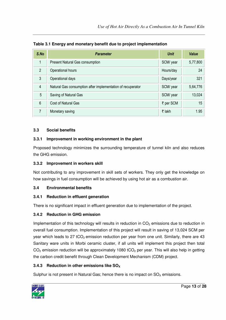
Table 3.1 Energy and monetary benefit due to project implementation
S.No Parameter Unit Value
1 Present Natural Gas consumption SCM/ year 5,77,800
2 Operational hours Hours/day 24
3 Operational days Days/year 321
4 Natural Gas consumption after implementation of recuperator SCM/ year 5,64,776
5 Saving of Natural Gas SCM/ year 13,024
6 Cost of Natural Gas ` per SCM 15
7 Monetary saving ` lakh 1.95
3.3 Social benefits
3.3.1 Improvement in working environment in the plant
Proposed technology minimizes the surrounding temperature of tunnel kiln and also reduces
the GHG emission.
3.3.2 Improvement in workers skill
Not contributing to any improvement in skill sets of workers. They only get the knowledge on
how savings in fuel consumption will be achieved by using hot air as a combustion air.
3.4 Environmental benefits
3.4.1 Reduction in effluent generation
There is no significant impact in effluent generation due to implementation of the project.
3.4.2 Reduction in GHG emission
Implementation of this technology will results in reduction in CO2 emissions due to reduction in
overall fuel consumption. Implementation of this project will result in saving of 13,024 SCM per
year which leads to 27 tCO2 emission reduction per year from one unit. Similarly, there are 43
Sanitary ware units in Morbi ceramic cluster, if all units will implement this project then total
CO2 emission reduction will be approximately 1080 tCO2 per year. This will also help in getting
the carbon credit benefit through Clean Development Mechanism (CDM) project.
3.4.3 Reduction in other emissions like SOX
Sulphur is not present in Natural Gas; hence there is no impact on SOX emissions.
Use of Hot Air Directly As a Combustion Air In Tunnel Kiln
Page 14 of 28
4 INSTALLATION OF PROPOSED EQUIPMENT
4.1 Cost of technology implementation
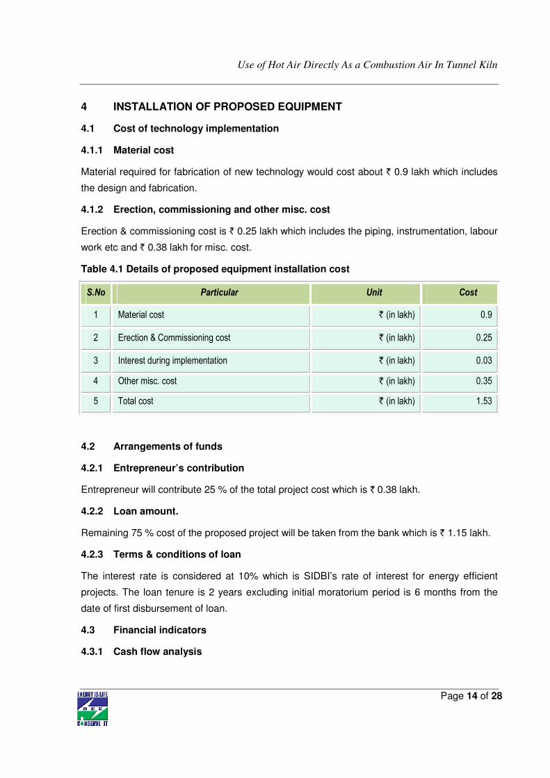
4.1.1 Material cost
Material required for fabrication of new technology would cost about ` 0.9 lakh which includes
the design and fabrication.
4.1.2 Erection, commissioning and other misc. cost
Erection & commissioning cost is ` 0.25 lakh which includes the piping, instrumentation, labour
work etc and ` 0.38 lakh for misc. cost.
Table 4.1 Details of proposed equipment installation cost
S.No Particular Unit Cost
1 Material cost ` (in lakh) 0.9
2 Erection & Commissioning cost ` (in lakh) 0.25
3 Interest during implementation ` (in lakh) 0.03
4 Other misc. cost ` (in lakh) 0.35
5 Total cost ` (in lakh) 1.53
4.2 Arrangements of funds
4.2.1 Entrepreneur’s contribution
Entrepreneur will contribute 25 % of the total project cost which is ` 0.38 lakh.
4.2.2 Loan amount.
Remaining 75 % cost of the proposed project will be taken from the bank which is ` 1.15 lakh.
4.2.3 Terms & conditions of loan
The interest rate is considered at 10% which is SIDBI’s rate of interest for energy efficient
projects. The loan tenure is 2 years excluding initial moratorium period is 6 months from the
date of first disbursement of loan.
4.3 Financial indicators
4.3.1 Cash flow analysis
Use of Hot Air Directly As a Combustion Air In Tunnel Kiln
Page 15 of 28
Profitability and cash flow statements have been worked out for a period of 2 years. The
financials have been worked out on the basis of certain reasonable assumptions, which are
outlined below.
The project is expected to achieve monetary savings of ` 1.95 lakh per annum.
• The Operation and Maintenance cost is estimated at 10 % of cost of total project with 5%
increase in every year as escalations.
• Interest on term loan is estimated at 10 %.
• Depreciation is provided as per the rates provided in the companies act.
Based on the above assumptions, profitability and cash flow statements have been prepared
and calculated in Annexure-5.
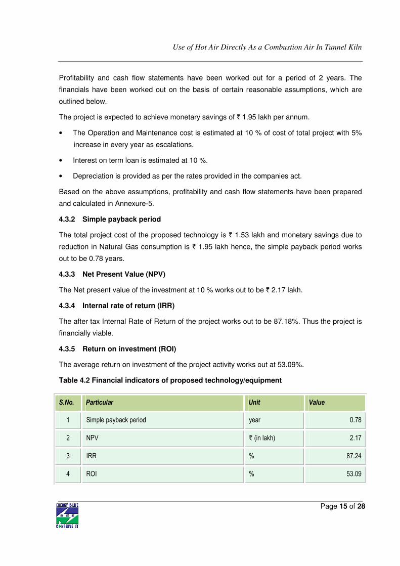
4.3.2 Simple payback period
The total project cost of the proposed technology is ` 1.53 lakh and monetary savings due to
reduction in Natural Gas consumption is ` 1.95 lakh hence, the simple payback period works
out to be 0.78 years.
4.3.3 Net Present Value (NPV)
The Net present value of the investment at 10 % works out to be ` 2.17 lakh.
4.3.4 Internal rate of return (IRR)
The after tax Internal Rate of Return of the project works out to be 87.18%. Thus the project is
financially viable.
4.3.5 Return on investment (ROI)
The average return on investment of the project activity works out at 53.09%.
Table 4.2 Financial indicators of proposed technology/equipment
S.No. Particular Unit Value
1 Simple payback period year 0.78
2 NPV ` (in lakh) 2.17
3 IRR % 87.24
4 ROI % 53.09
Use of Hot Air Directly As a Combustion Air In Tunnel Kiln
Page 16 of 28
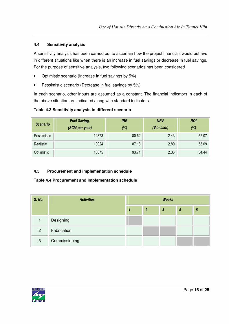
4.4 Sensitivity analysis
A sensitivity analysis has been carried out to ascertain how the project financials would behave
in different situations like when there is an increase in fuel savings or decrease in fuel savings.
For the purpose of sensitive analysis, two following scenarios has been considered
• Optimistic scenario (Increase in fuel savings by 5%)
• Pessimistic scenario (Decrease in fuel savings by 5%)
In each scenario, other inputs are assumed as a constant. The financial indicators in each of
the above situation are indicated along with standard indicators
Table 4.3 Sensitivity analysis in different scenario
4.5 Procurement and implementation schedule
Table 4.4 Procurement and implementation schedule
S. No. Activities Weeks
1 2 3 4 5
1 Designing
2 Fabrication
3 Commissioning
Scenario Fuel Saving,
(SCM per year)
IRR
(%)
NPV
(`̀̀̀ in lakh)
ROI
(%)
Pessimistic 12373 80.62 2.43 52.07
Realistic 13024 87.18 2.80 53.09
Optimistic 13675 93.71 2.36 54.44
Use of Hot Air Directly As a Combustion Air In Tunnel Kiln
Page 17 of 28
Annexure
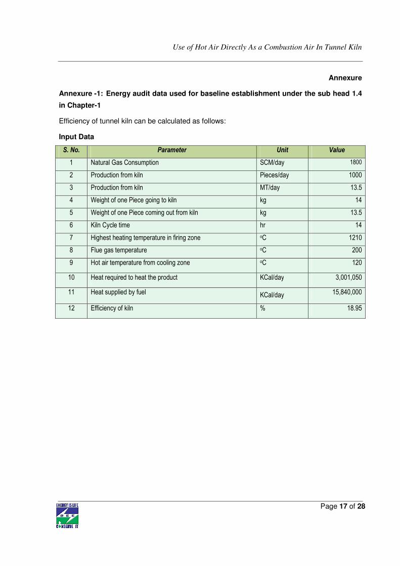
Annexure -1: Energy audit data used for baseline establishment under the sub head 1.4
in Chapter-1
Efficiency of tunnel kiln can be calculated as follows:
Input Data
S. No. Parameter Unit Value
1 Natural Gas Consumption SCM/day 1800
2 Production from kiln Pieces/day 1000
3 Production from kiln MT/day 13.5
4 Weight of one Piece going to kiln kg 14
5 Weight of one Piece coming out from kiln kg 13.5
6 Kiln Cycle time hr 14
7 Highest heating temperature in firing zone oC 1210
8 Flue gas temperature oC 200
9 Hot air temperature from cooling zone oC 120
10 Heat required to heat the product KCal/day 3,001,050
11 Heat supplied by fuel KCal/day 15,840,000
12 Efficiency of kiln % 18.95
Use of Hot Air Directly As a Combustion Air In Tunnel Kiln
Page 18 of 28
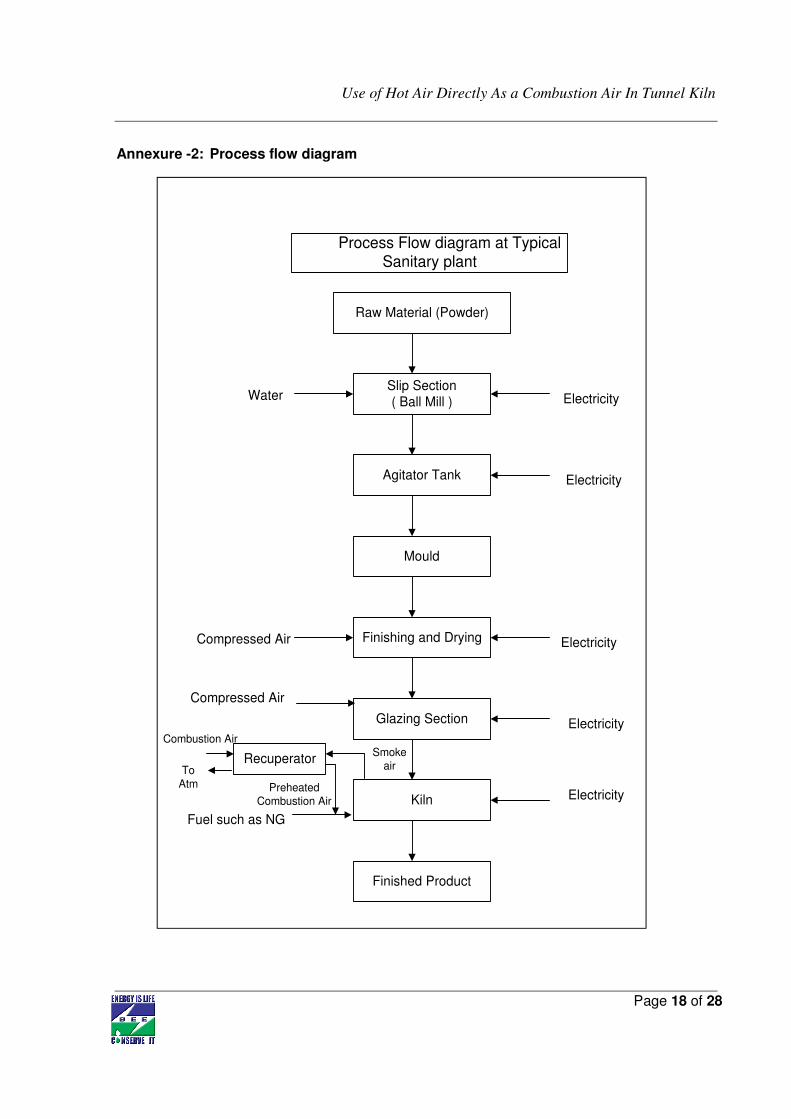
Process Flow diagram at TypicalSanitary plant
Raw Material (Powder)
Slip Section
( Ball Mill )
Agitator Tank
Mould
Finishing and Drying
Glazing Section
Kiln
Finished Product
Water Electricity
Electricity
Electricity
Electricity
Electricity
Compressed Air
Fuel such as NG
Compressed Air
Recuperator
Combustion AirSmoke
airTo
Atm Preheated
Combustion Air
Annexure -2: Process flow diagram

Use of Hot Air Directly As a Combustion Air In Tunnel Kiln
Page 19 of 28
Annexure -3: Detailed equipment assessment report
S.No. Particular Unit Existing Technology
Proposed Technology
2 Combustion flow rate m3/hr 860 860
3 Inlet combustion air temperature 0C 40 120
5 Working day in a year days 321 321
6 Natural Gas Consumption SCM/day 1800 1759.5
7 Gross calorific value of Natural Gas KCal/SCM 8800 8800
8 Specific heat of combustion air KCal/kg0C 0.24 0.24
10 Density of air Kg/m3 1.12 1.12
15 Heat gain by combustion air KCal/ hr 17,799
jy16 Equivalent Natural Gas saving SCM/hour 1.69
17 Saving in Natural Gas consumption SCM/day 40.53
18 Saving in Natural Gas consumption % 2.25
19 Saving in Natural Gas consumption SCM/year 13,024
20 Cost of Natural Gas ` SCM 15
21 Monetary saving ` (in lakh) 1.95
Use of Hot Air Directly As a Combustion Air In Tunnel Kiln
Page 20 of 28
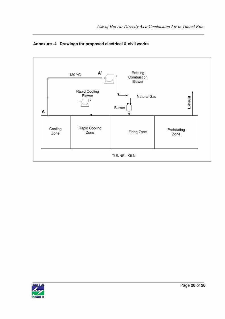
Annexure -4 Drawings for proposed electrical & civil works
A
TUNNEL KILN
Firing ZonePreheating
Zone
Rapid Cooling
ZoneCoolingZone
Natural Gas
Exhaust
Rapid Cooling
Blower
120 OC
Burner
Existing
CombustionBlower
A'
Use of Hot Air Directly As a Combustion Air In Tunnel Kiln
Page 21 of 28
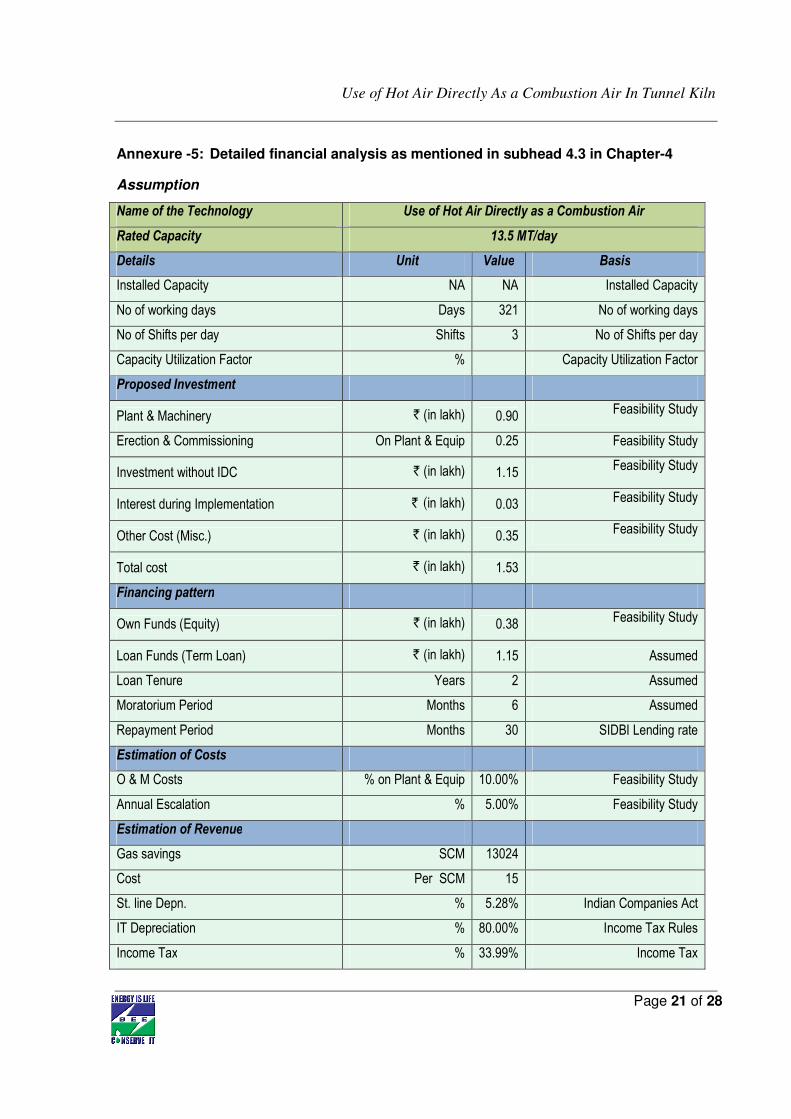
Annexure -5: Detailed financial analysis as mentioned in subhead 4.3 in Chapter-4
Assumption
Name of the Technology Use of Hot Air Directly as a Combustion Air
Rated Capacity 13.5 MT/day
Details Unit Value Basis
Installed Capacity NA NA Installed Capacity
No of working days Days 321 No of working days
No of Shifts per day Shifts 3 No of Shifts per day
Capacity Utilization Factor % Capacity Utilization Factor
Proposed Investment
Plant & Machinery ` (in lakh) 0.90 Feasibility Study
Erection & Commissioning On Plant & Equip 0.25 Feasibility Study
Investment without IDC ` (in lakh) 1.15 Feasibility Study
Interest during Implementation ` (in lakh) 0.03 Feasibility Study
Other Cost (Misc.) ` (in lakh) 0.35 Feasibility Study
Total cost ` (in lakh) 1.53
Financing pattern
Own Funds (Equity) ` (in lakh) 0.38 Feasibility Study
Loan Funds (Term Loan) ` (in lakh) 1.15 Assumed
Loan Tenure Years 2 Assumed
Moratorium Period Months 6 Assumed
Repayment Period Months 30 SIDBI Lending rate
Estimation of Costs
O & M Costs % on Plant & Equip 10.00% Feasibility Study
Annual Escalation % 5.00% Feasibility Study
Estimation of Revenue
Gas savings SCM 13024
Cost Per SCM 15
St. line Depn. % 5.28% Indian Companies Act
IT Depreciation % 80.00% Income Tax Rules
Income Tax % 33.99% Income Tax
Use of Hot Air Directly As a Combustion Air In Tunnel Kiln
Page 22 of 28
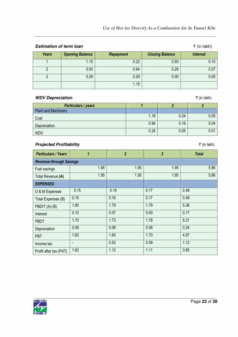
Estimation of term loan ` (in lakh)
Years Opening Balance Repayment Closing Balance Interest
1 1.15 0.22 0.93 0.10
2 0.93 0.64 0.29 0.07
3 0.29 0.29 0.00 0.00
1.15
WDV Depreciation ` (in lakh)
Particulars / years 1 2 3
Plant and Machinery
Cost 1.18 0.24 0.05
Depreciation 0.94 0.19 0.04
WDV 0.24 0.05 0.01
Projected Profitability ` (in lakh)
Particulars / Years 1 2 3 Total
Revenue through Savings
Fuel savings 1.95 1.95 1.95 5.86
Total Revenue (A) 1.95 1.95 1.95 5.86
EXPENSES
O & M Expenses 0.15 0.16 0.17 0.48
Total Expenses (B) 0.15 0.16 0.17 0.48
PBDIT (A)-(B) 1.80 1.79 1.79 5.38
Interest 0.10 0.07 0.00 0.17
PBDT 1.70 1.73 1.78 5.21
Depreciation 0.08 0.08 0.08 0.24
PBT 1.62 1.65 1.70 4.97
Income tax - 0.52 0.59 1.12
Profit after tax (PAT) 1.62 1.12 1.11 3.85
Use of Hot Air Directly As a Combustion Air In Tunnel Kiln
Page 23 of 28
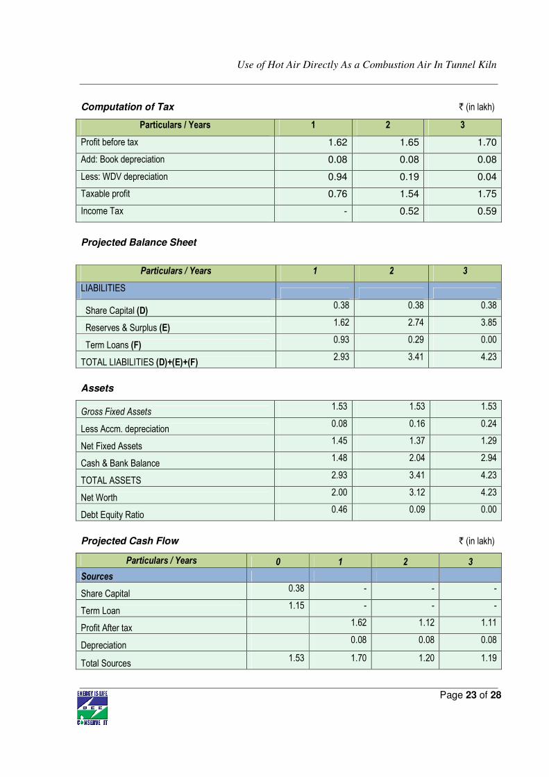
Computation of Tax ` (in lakh)
Particulars / Years 1 2 3
Profit before tax 1.62 1.65 1.70
Add: Book depreciation 0.08 0.08 0.08
Less: WDV depreciation 0.94 0.19 0.04
Taxable profit 0.76 1.54 1.75
Income Tax - 0.52 0.59
Projected Balance Sheet
Particulars / Years 1 2 3
LIABILITIES
Share Capital (D) 0.38 0.38 0.38
Reserves & Surplus (E) 1.62 2.74 3.85
Term Loans (F) 0.93 0.29 0.00
TOTAL LIABILITIES (D)+(E)+(F) 2.93 3.41 4.23
Assets
Gross Fixed Assets 1.53 1.53 1.53
Less Accm. depreciation 0.08 0.16 0.24
Net Fixed Assets 1.45 1.37 1.29
Cash & Bank Balance 1.48 2.04 2.94
TOTAL ASSETS 2.93 3.41 4.23
Net Worth 2.00 3.12 4.23
Debt Equity Ratio 0.46 0.09 0.00
Projected Cash Flow ` (in lakh)
Particulars / Years 0 1 2 3
Sources
Share Capital 0.38 - - -
Term Loan 1.15 - - -
Profit After tax 1.62 1.12 1.11
Depreciation 0.08 0.08 0.08
Total Sources 1.53 1.70 1.20 1.19
Use of Hot Air Directly As a Combustion Air In Tunnel Kiln
Page 24 of 28
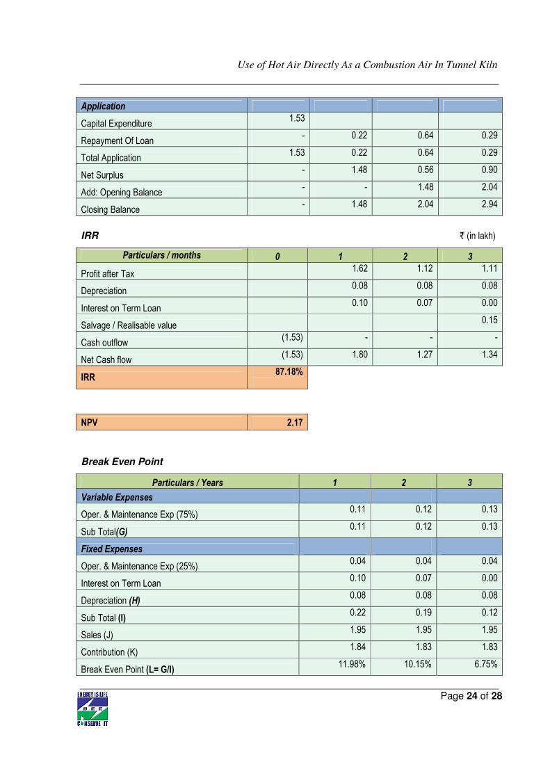
Application
Capital Expenditure 1.53
Repayment Of Loan - 0.22 0.64 0.29
Total Application 1.53 0.22 0.64 0.29
Net Surplus - 1.48 0.56 0.90
Add: Opening Balance - - 1.48 2.04
Closing Balance - 1.48 2.04 2.94
IRR ` (in lakh)
Particulars / months 0 1 2 3
Profit after Tax 1.62 1.12 1.11
Depreciation 0.08 0.08 0.08
Interest on Term Loan 0.10 0.07 0.00
Salvage / Realisable value 0.15
Cash outflow (1.53) - - -
Net Cash flow (1.53) 1.80 1.27 1.34
IRR 87.18%
NPV 2.17
Break Even Point
Particulars / Years 1 2 3
Variable Expenses
Oper. & Maintenance Exp (75%) 0.11 0.12 0.13
Sub Total(G) 0.11 0.12 0.13
Fixed Expenses
Oper. & Maintenance Exp (25%) 0.04 0.04 0.04
Interest on Term Loan 0.10 0.07 0.00
Depreciation (H) 0.08 0.08 0.08
Sub Total (I) 0.22 0.19 0.12
Sales (J) 1.95 1.95 1.95
Contribution (K) 1.84 1.83 1.83
Break Even Point (L= G/I) 11.98% 10.15% 6.75%
Use of Hot Air Directly As a Combustion Air In Tunnel Kiln
Page 25 of 28
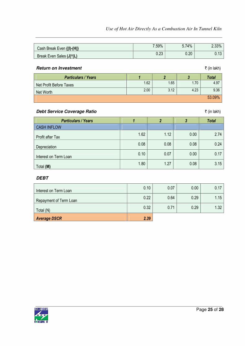
Cash Break Even {(I)-(H)} 7.59% 5.74% 2.33%
Break Even Sales (J)*(L) 0.23 0.20 0.13
Return on Investment ` (in lakh)
Particulars / Years 1 2 3 Total
Net Profit Before Taxes 1.62 1.65 1.70 4.97
Net Worth 2.00 3.12 4.23 9.36
53.09%
Debt Service Coverage Ratio ` (in lakh)
Particulars / Years 1 2 3 Total
CASH INFLOW
Profit after Tax 1.62 1.12 0.00 2.74
Depreciation 0.08 0.08 0.08 0.24
Interest on Term Loan 0.10 0.07 0.00 0.17
Total (M) 1.80 1.27 0.08 3.15
DEBT
Interest on Term Loan 0.10 0.07 0.00 0.17
Repayment of Term Loan 0.22 0.64 0.29 1.15
Total (N) 0.32 0.71 0.29 1.32
Average DSCR 2.39
Use of Hot Air Directly As a Combustion Air In Tunnel Kiln
Page 26 of 28
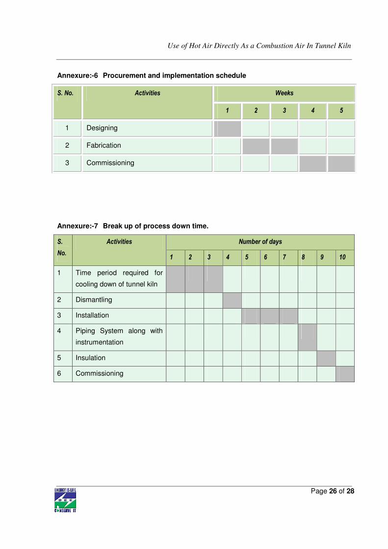
Annexure:-6 Procurement and implementation schedule
S. No. Activities Weeks
1 2 3 4 5
1 Designing
2 Fabrication
3 Commissioning
Annexure:-7 Break up of process down time.
S.
No.
Activities Number of days
1 2 3 4 5 6 7 8 9 10
1 Time period required for
cooling down of tunnel kiln
2 Dismantling
3 Installation
4 Piping System along with
instrumentation
5 Insulation
6 Commissioning
Use of Hot Air Directly As a Combustion Air In Tunnel Kiln
Page 27 of 28
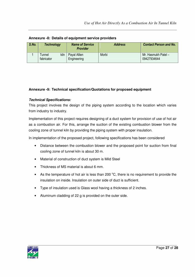
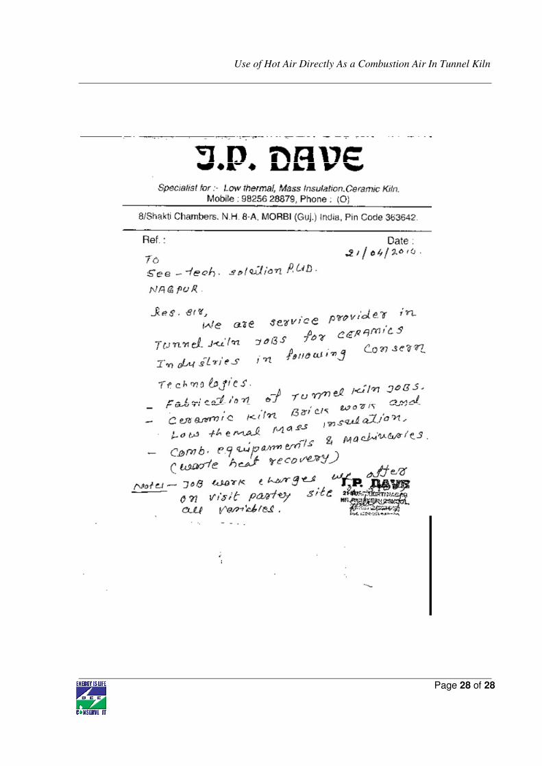
Annexure -8: Details of equipment service providers
S.No. Technology Name of Service Provider
Address Contact Person and No.
1 Tunnel kiln fabricator
Payal Allien Engineering
Morbi Mr. Hasmukh Patel – 09427934644
Annexure -9: Technical specification/Quotations for proposed equipment
Technical Specifications:
This project involves the design of the piping system according to the location which varies
from industry to industry.
Implementation of this project requires designing of a duct system for provision of use of hot air
as a combustion air. For this, arrange the suction of the existing combustion blower from the
cooling zone of tunnel kiln by providing the piping system with proper insulation.
In implementation of the proposed project, following specifications has been considered
• Distance between the combustion blower and the proposed point for suction from final
cooling zone of tunnel kiln is about 30 m.
• Material of construction of duct system is Mild Steel
• Thickness of MS material is about 6 mm.
• As the temperature of hot air is less than 200 oC, there is no requirement to provide the
insulation on inside. Insulation on outer side of duct is sufficient.
• Type of insulation used is Glass wool having a thickness of 2 inches.
• Aluminum cladding of 22 g is provided on the outer side.
Use of Hot Air Directly As a Combustion Air In Tunnel Kiln
Page 28 of 28
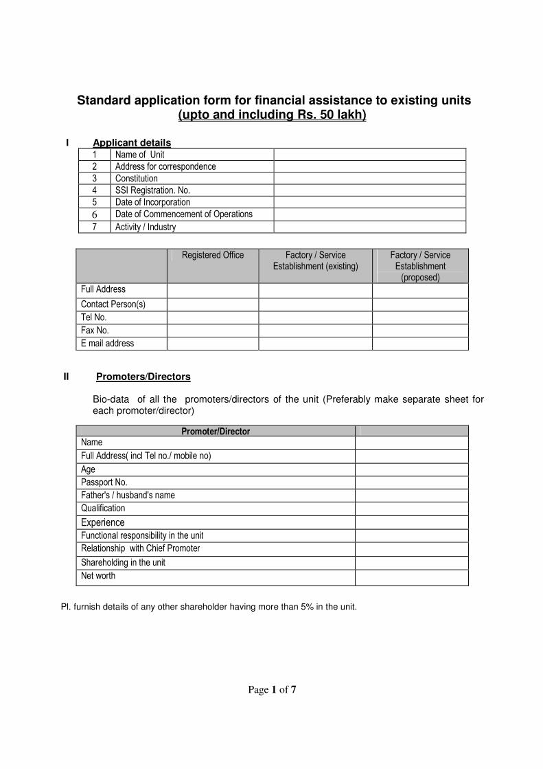
Page 1 of 7
Standard application form for financial assistance to existing units (upto and including Rs. 50 lakh)
I Applicant details
1 Name of Unit
2 Address for correspondence
3 Constitution
4 SSI Registration. No.
5 Date of Incorporation
6 Date of Commencement of Operations
7 Activity / Industry
Registered Office Factory / Service Establishment (existing)
Factory / Service Establishment (proposed)
Full Address
Contact Person(s)
Tel No.
Fax No.
E mail address
II Promoters/Directors Bio-data of all the promoters/directors of the unit (Preferably make separate sheet for
each promoter/director)
Promoter/Director
Name
Full Address( incl Tel no./ mobile no)
Age
Passport No.
Father's / husband's name
Qualification
Experience
Functional responsibility in the unit
Relationship with Chief Promoter
Shareholding in the unit
Net worth
Pl. furnish details of any other shareholder having more than 5% in the unit.
Application form for Loans upto and including Rs. 50 lakh
Page 2 of 7
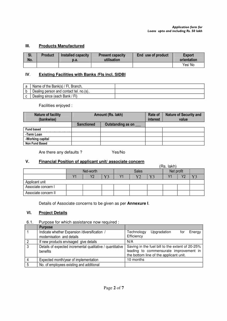
III. Products Manufactured
Sl. No.
Product Installed capacity p.a.
Present capacity utilisation
End use of product Export orientation
Yes/ No
IV. Existing Facilities with Banks /FIs incl. SIDBI a Name of the Bank(s) / FI, Branch,
b Dealing person and contact tel. no.(s)..
c Dealing since (each Bank / FI)
Facilities enjoyed :
Nature of facility (bankwise)
Amount (Rs. lakh) Rate of interest
Nature of Security and value
Sanctioned Outstanding as on ___ ___
Fund based Basedkfjdffkldkfjdfkjdfkjdfkdjfkdjf
-Term Loan
-Working capital
Non Fund Based
Are there any defaults ? Yes/No V. Financial Position of applicant unit/ associate concern (Rs. lakh)
Net-worth Sales Net profit
Y1 Y2 Y3 Y1 Y2 Y3 Y1 Y2 Y3 Applicant unit Associate concern I
Associate concern II
Details of Associate concerns to be given as per Annexure I. VI. Project Details 6.1. Purpose for which assistance now required : Purpose
1 Indicate whether Expansion /diversification / modernisation and details
Technology Upgradation for Energy Efficiency
2 If new products envisaged give details N/A
3 Details of expected incremental qualitative / quantitative benefits
Saving in the fuel bill to the extent of 20-25% leading to commensurate improvement in the bottom line of the applicant unit.
4 Expected month/year of implementation 10 months
5 No. of employees existing and additional
Application form for Loans upto and including Rs. 50 lakh
Page 3 of 7
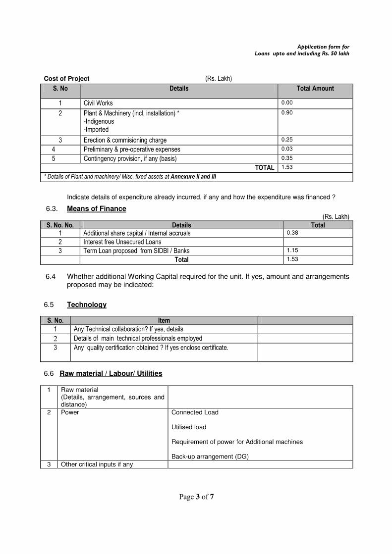
Cost of Project (Rs. Lakh)
S. No Details Total Amount
1 Civil Works 0.00
2 Plant & Machinery (incl. installation) * -Indigenous -Imported
0.90
3 Erection & commisioning charge 0.25
4 Preliminary & pre-operative expenses &
0.03
5 Contingency provision, if any (basis) 0.35
TOTAL 1.53
* Details of Plant and machinery/ Misc. fixed assets at Annexure II and III
Indicate details of expenditure already incurred, if any and how the expenditure was financed ?
6.3. Means of Finance (Rs. Lakh)
S. No. No. Details Total 1 Additional share capital / Internal accruals 0.38
2 Interest free Unsecured Loans
3 Term Loan proposed from SIDBI / Banks 1.15
Total 1.53
6.4 Whether additional Working Capital required for the unit. If yes, amount and arrangements proposed may be indicated:
6.5 Technology
S. No. Item
1 Any Technical collaboration? If yes, details
2 Details of main technical professionals employed
3 Any quality certification obtained ? If yes enclose certificate.
6.6 Raw material / Labour/ Utilities 1 Raw material
(Details, arrangement, sources and distance)
2 Power Connected Load Utilised load Requirement of power for Additional machines Back-up arrangement (DG)
3 Other critical inputs if any
Application form for Loans upto and including Rs. 50 lakh
Page 4 of 7
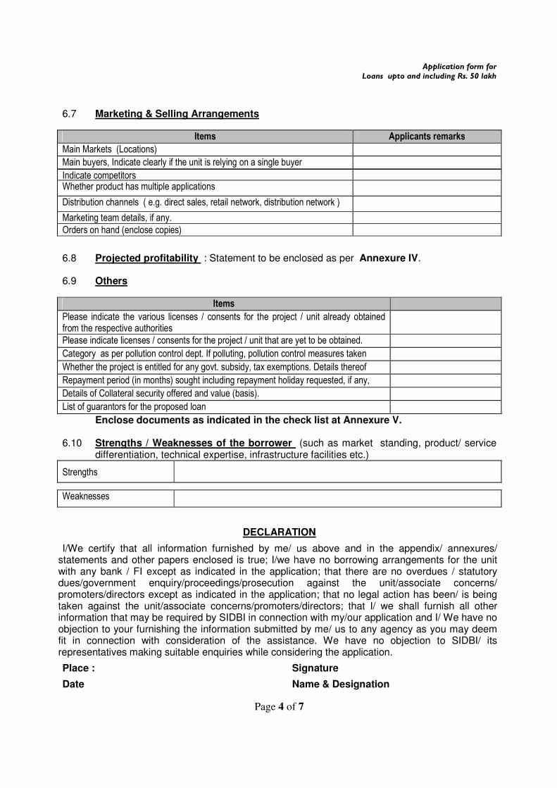
6.7 Marketing & Selling Arrangements
Items Applicants remarks
Main Markets (Locations)
Main buyers, Indicate clearly if the unit is relying on a single buyer
Locational advantagesIndicate competitors
Whether product has multiple applications
Distribution channels ( e.g. direct sales, retail network, distribution network )
Marketing team details, if any.
Orders on hand (enclose copies)
6.8 Projected profitability : Statement to be enclosed as per Annexure IV.
6.9 Others
Items Please indicate the various licenses / consents for the project / unit already obtained from the respective authorities
Please indicate licenses / consents for the project / unit that are yet to be obtained. Category as per pollution control dept. If polluting, pollution control measures taken Whether the project is entitled for any govt. subsidy, tax exemptions. Details thereof Repayment period (in months) sought including repayment holiday requested, if any, Details of Collateral security offered and value (basis). List of guarantors for the proposed loan Enclose documents as indicated in the check list at Annexure V.
6.10 Strengths / Weaknesses of the borrower (such as market standing, product/ service
differentiation, technical expertise, infrastructure facilities etc.)
Strengths
Weaknesses
DECLARATION
I/We certify that all information furnished by me/ us above and in the appendix/ annexures/ statements and other papers enclosed is true; I/we have no borrowing arrangements for the unit with any bank / FI except as indicated in the application; that there are no overdues / statutory dues/government enquiry/proceedings/prosecution against the unit/associate concerns/ promoters/directors except as indicated in the application; that no legal action has been/ is being taken against the unit/associate concerns/promoters/directors; that I/ we shall furnish all other information that may be required by SIDBI in connection with my/our application and I/ We have no objection to your furnishing the information submitted by me/ us to any agency as you may deem fit in connection with consideration of the assistance. We have no objection to SIDBI/ its representatives making suitable enquiries while considering the application.
Place : Signature
Date Name & Designation
Application form for Loans upto and including Rs. 50 lakh
Page 5 of 7
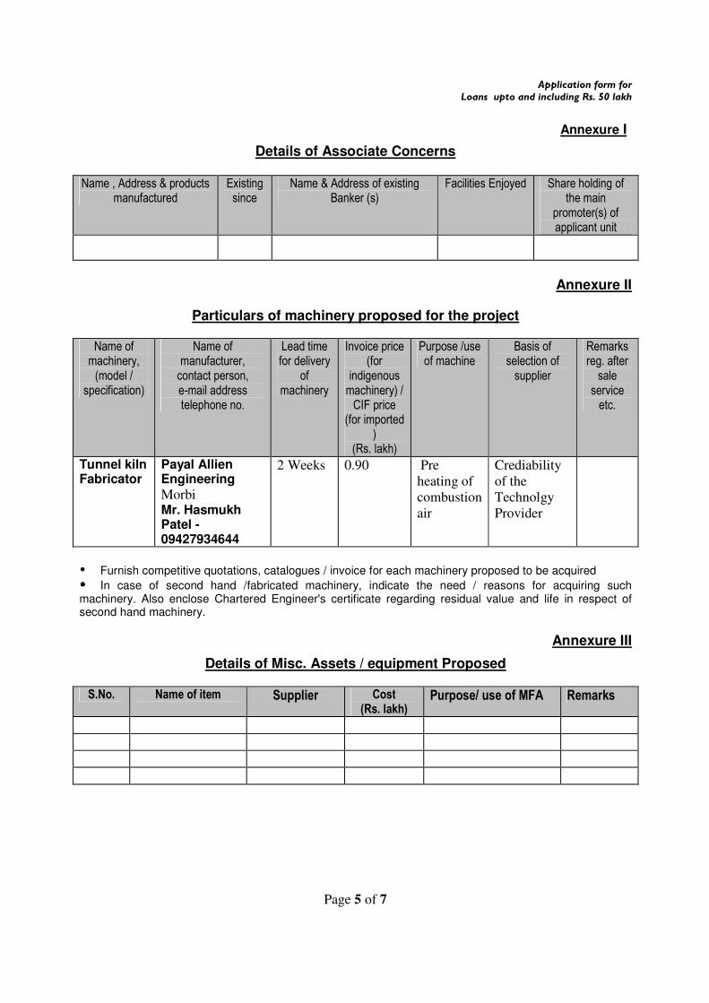
Annexure I
Details of Associate Concerns Name , Address & products
manufactured Existing since
Name & Address of existing Banker (s)
Facilities Enjoyed Share holding of the main
promoter(s) of applicant unit
Annexure II
Particulars of machinery proposed for the project
Name of machinery, (model /
specification)
Name of manufacturer, contact person, e-mail address telephone no.
Lead time for delivery
of machinery
Invoice price (for
indigenous machinery) / CIF price
(for imported )
(Rs. lakh)
Purpose /use of machine
Basis of selection of supplier
Remarks reg. after sale
service etc.
Tunnel kiln Fabricator
Payal Allien Engineering Morbi Mr. Hasmukh Patel - 09427934644
2 Weeks 0.90 Pre
heating of
combustion
air
Crediability
of the
Technolgy
Provider
� Furnish competitive quotations, catalogues / invoice for each machinery proposed to be acquired
���� In case of second hand /fabricated machinery, indicate the need / reasons for acquiring such machinery. Also enclose Chartered Engineer's certificate regarding residual value and life in respect of second hand machinery.
Annexure III
Details of Misc. Assets / equipment Proposed S.No. Name of item Supplier Cost
(Rs. lakh) Purpose/ use of MFA Remarks
Application form for Loans upto and including Rs. 50 lakh
Page 6 of 7
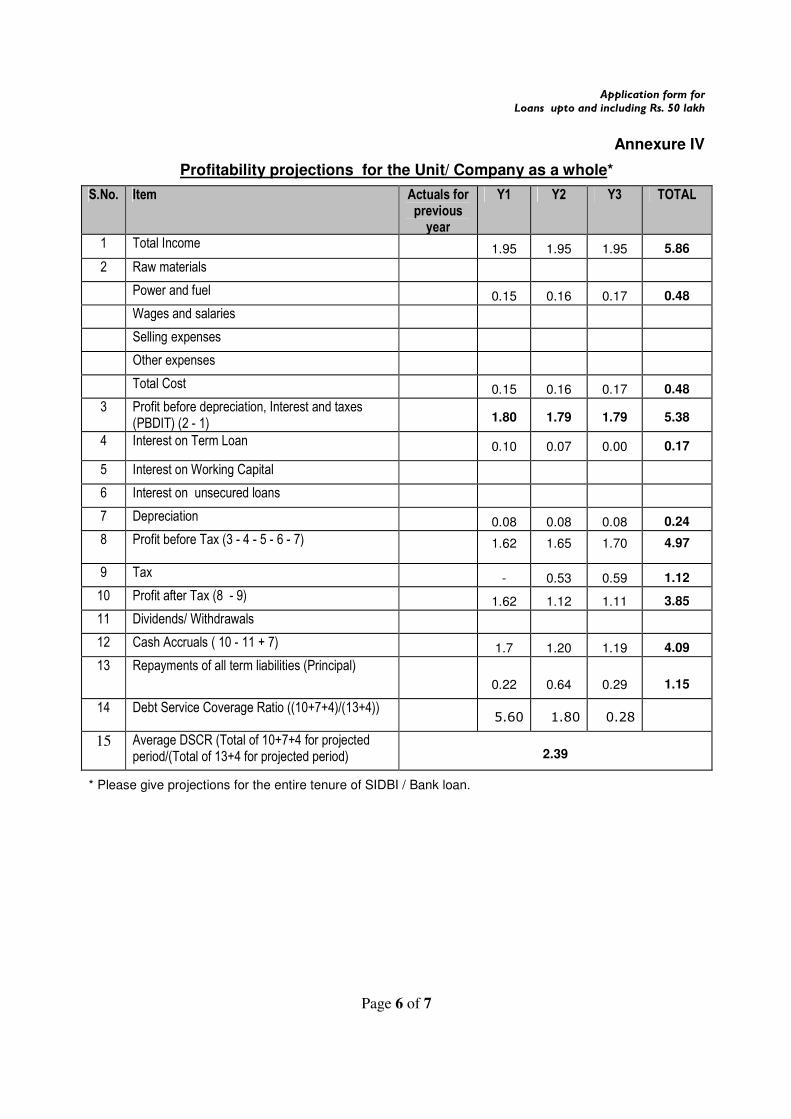
Annexure IV
Profitability projections for the Unit/ Company as a whole*
S.No. Item Actuals for previous year
Y1 Y2 Y3 TOTAL
1 Total Income 1.95 1.95 1.95 5.86
2 Raw materials
Power and fuel 0.15 0.16 0.17 0.48
Wages and salaries
Selling expenses
Other expenses
Total Cost 0.15 0.16 0.17 0.48
3 Profit before depreciation, Interest and taxes (PBDIT) (2 - 1)
1.80 1.79 1.79 5.38
4 Interest on Term Loan 0.10 0.07 0.00 0.17
5 Interest on Working Capital
6 Interest on unsecured loans
7 Depreciation 0.08 0.08 0.08 0.24
8 Profit before Tax (3 - 4 - 5 - 6 - 7) 1.62 1.65 1.70 4.97
9 Tax - 0.53 0.59 1.12
10 Profit after Tax (8 - 9) 1.62 1.12 1.11 3.85
11 Dividends/ Withdrawals
12 Cash Accruals ( 10 - 11 + 7) 1.7 1.20 1.19 4.09
13 Repayments of all term liabilities (Principal)
0.22 0.64 0.29 1.15
14 Debt Service Coverage Ratio ((10+7+4)/(13+4)) 5.60 1.80 0.28
15 Average DSCR (Total of 10+7+4 for projected period/(Total of 13+4 for projected period)
2.39
* Please give projections for the entire tenure of SIDBI / Bank loan.
Application form for Loans upto and including Rs. 50 lakh
Page 7 of 7
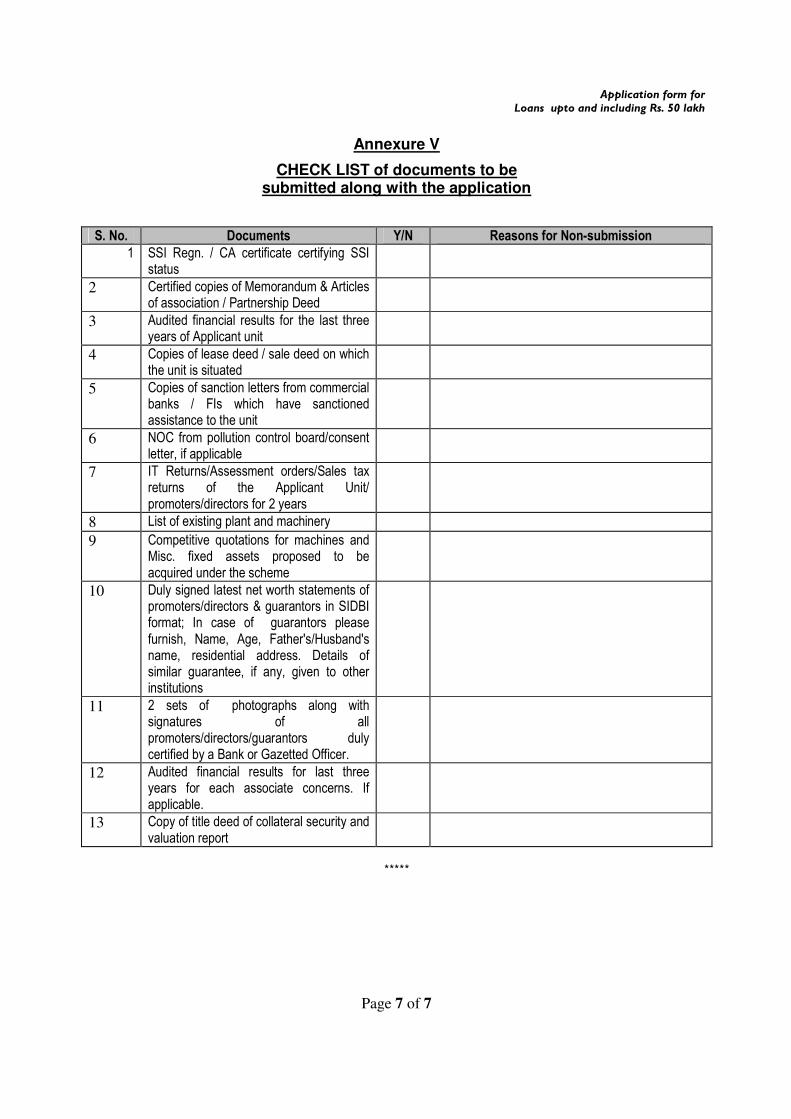
Annexure V
CHECK LIST of documents to be submitted along with the application
S. No. Documents Y/N Reasons for Non-submission
1 SSI Regn. / CA certificate certifying SSI status
2 Certified copies of Memorandum & Articles of association / Partnership Deed
3 Audited financial results for the last three years of Applicant unit
4 Copies of lease deed / sale deed on which the unit is situated
5 Copies of sanction letters from commercial banks / FIs which have sanctioned assistance to the unit
6 NOC from pollution control board/consent letter, if applicable
7 IT Returns/Assessment orders/Sales tax returns of the Applicant Unit/ promoters/directors for 2 years
8 List of existing plant and machinery
9 Competitive quotations for machines and Misc. fixed assets proposed to be acquired under the scheme
10 Duly signed latest net worth statements of promoters/directors & guarantors in SIDBI format; In case of guarantors please furnish, Name, Age, Father's/Husband's name, residential address. Details of similar guarantee, if any, given to other institutions
11 2 sets of photographs along with signatures of all promoters/directors/guarantors duly certified by a Bank or Gazetted Officer.
12 Audited financial results for last three years for each associate concerns. If applicable.
13 Copy of title deed of collateral security and valuation report
*****

Bureau of Energy Efficiency (BEE) (Ministry of Power, Government of India) 4th Floor, Sewa Bhawan, R. K. Puram, New Delhi – 110066 Ph.: +91 – 11 – 26179699 (5 Lines), Fax: +91 – 11 – 26178352
Websites: www.bee-india.nic.in, www.energymanagertraining.com
SEE-Tech Solutions Pvt. Ltd 11/5, MIDC, Infotech Park, Near VRCE Telephone Exchange, South Ambazari Road, Nagpur – 440022 Website: www.letsconserve.org
India SME Technology Services Ltd DFC Building, Plot No.37-38, D-Block, Pankha Road, Institutional Area, Janakpuri, New Delhi-110058 Tel: +91-11-28525534, Fax: +91-11-28525535 Website: www.techsmall.com