Embed Size (px)
Citation preview
DETECTION AND SEMI-AUTOMATIC CORRECTIONOF GEOMETRIC INACCURACIES IN IFC FILES
G.N. Lilis1, G.I. Giannakis1 and D.V. Rovas1,21Department of Production Engineering and Management, Technical University of Crete, Chania, Greece
2Group of Energy Systems, Fraunhofer, Institute for Building Physics, Germany
ABSTRACTAccurate representation of geometry-related parame-ters is a prerequisite for the generation of building ther-mal simulation models. In case geometric data areextracted from IFC files, three types of geometricalerrors are often encountered: clash errors where twobuilding solids intersect, space definition errors wherea building space volume is incorrectly defined leav-ing volume gaps between the space and neighboringbuilding entities (walls, slabs,...) and surface orienta-tion errors, where the normal vector of some boundarysurfaces of building solids points to the wrong direc-tion, generating a misconception on which area is in-side or outside the solid. These errors are introducedeither in the design process or during export from theBIM authoring tool. In this paper, error detection andcorrection algorithms are introduced to address eachindividual error type. The algorithms are tested on thegeometrical data of the IFC files of two office build-ings, where errors of the types mentioned above weredetected and automatically corrected.
INTRODUCTIONEnergy performance simulation of buildings can be avaluable tool for estimation of energy-related param-eters. In current state of practice a lot of effort is re-quired to manually generate simulation model inputs,with significant part of this effort spent in geometry-related aspects. Building Information Models (BIM),such as the Industry Foundation Classes (IFC) (ISO-16739, 2013) provide an information-rich repositoryfor Extraction of required data. Transformation ofthis information (e.g. by identification of second-levelboundary information) (Bazjanac, 2010), and Loadingto another data model (e.g. Simmodel) or direct gen-eration of the input file (e.g. idf file for EnergyPlus)can help automate the model-generation process. SuchExtraction, Transformation and Loading (ETL) layershave been the topic of intense research interest in re-cent years. The quality of the input IFC data is ofparamount importance in establishing such ETL pro-cesses. Very often errors introduced in the design ofthe BIM model or during the extraction from the au-thoring tool to IFC, result in poor- quality models.Unavoidably, poor quality of geometric input has asizeable impact in the transformation process, mostnotably in the identification of the building’s second-level space boundary topology. The second-levelspace boundary topology consists of a set of surfacepairs which are defined at the boundaries betweenbuilding constructions (walls, slabs,...) and internal
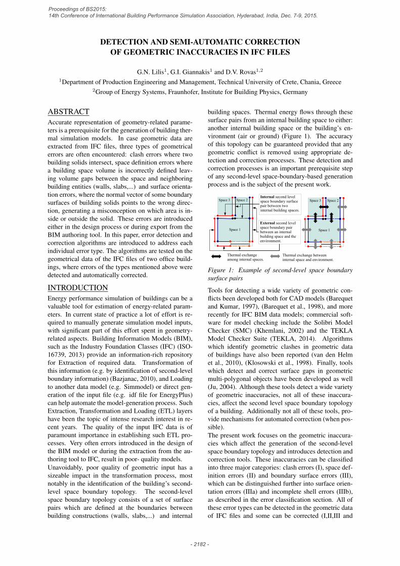
building spaces. Thermal energy flows through thesesurface pairs from an internal building space to either:another internal building space or the building’s en-vironment (air or ground) (Figure 1). The accuracyof this topology can be guaranteed provided that anygeometric conflict is removed using appropriate de-tection and correction processes. These detection andcorrection processes is an important prerequisite stepof any second-level space-boundary-based generationprocess and is the subject of the present work.
Space 1
Space 2Space 3Internal second level space boundary surface pair between two internal building spaces.
External second level space boundary pair between an internal building space and the environment.
Space 1
Space 2
Thermal exchange betweeninternal space and environment.
Thermal exchange among internal spaces.
Space 3
Figure 1: Example of second-level space boundarysurface pairs
Tools for detecting a wide variety of geometric con-flicts been developed both for CAD models (Barequetand Kumar, 1997), (Barequet et al., 1998), and morerecently for IFC BIM data models; commercial soft-ware for model checking include the Solibri ModelChecker (SMC) (Khemlani, 2002) and the TEKLAModel Checker Suite (TEKLA, 2014). Algorithmswhich identify geometric clashes in geometric dataof buildings have also been reported (van den Helmet al., 2010), (Klosowski et al., 1998). Finally, toolswhich detect and correct surface gaps in geometricmulti-polygonal objects have been developed as well(Ju, 2004). Although these tools detect a wide varietyof geometric inaccuracies, not all of these inaccura-cies, affect the second level space boundary topologyof a building. Additionally not all of these tools, pro-vide mechanisms for automated correction (when pos-sible).The present work focuses on the geometric inaccura-cies which affect the generation of the second-levelspace boundary topology and introduces detection andcorrection tools. These inaccuracies can be classifiedinto three major categories: clash errors (I), space def-inition errors (II) and boundary surface errors (III),which can be distinguished further into surface orien-tation errors (IIIa) and incomplete shell errors (IIIb),as described in the error classification section. All ofthese error types can be detected in the geometric dataof IFC files and some can be corrected (I,II,III and
Proceedings of BS2015: 14th Conference of International Building Performance Simulation Association, Hyderabad, India, Dec. 7-9, 2015.
- 2182 -

IIIa), using detection and correction algorithms de-scribed in respective detection and correction sections.Finally, these detection and correction algorithms areapplied on the IFC files of two office buildings and ob-tained results are presented in the examples section.
NotationTo ease the comprehension of the introduced al-gorithms, certain mathematical notation is adopted,which consists of the following set of symbols:
• Solid: is denoted with a bold capital letter e.g.S and represents the subset of the three dimen-sional space, the solid occupies.
• Surface set: is denoted with a calligraphic cap-ital letter e.g. S. A surface set contains a fi-nite number of polygonal surfaces e.g. S ={S1, S2, ..., SN}.
• BSP-tree of surface set: is denoted with T andthe surface set letter e.g. TS . A BSP-tree isthe binary space partitioning tree of an orientedspace set S (Thibault and Naylor, 1987).
• Boundary of a solid: is denoted using ∂ in frontof a bold capital letter which denotes the solide.g. ∂S. The boundary of a solid is a surface setwhich contains all the boundary surfaces of thesolid.
• Polygonal surface: is denoted with a capital let-ter e.g. Si.
• Normal vector of a polygonal surfaces: is de-noted with n and the capital letter of the polyg-onal surface e.g. nSi .
GEOMETRIC REPRESENTATIONThe developed geometric error detection and correc-tion tools, use two geometric solid representationswhich are described in the following sections.
Boundary representation (B-rep)
Right-hand thumbdirection ...
I. Boundary of polyhedron II. Boundary polygon
Figure 2: Example of a boundary representation (B-rep) of a building solid S.
The solid representation used in the detection and cor-rection tools, is the boundary representation method,or B-rep (Jackson, 1995). A B-rep of a building solid Sis defined as the set of the solid boundary polygon sur-faces: ∂S = {S1, ..., SN}, (part I of Figure 2). Eachsurface polygon in the B-rep Si is correctly orientedwhen its normal vector (nSi ) direction evaluated us-ing the right-hand rule (part II of Figure 2) points out-wards. If the boundary points are ordered following
this right-hand rule (1st, 2nd, ...), then the boundarysurface is oriented correctly (Part II of Figure 2).
Binary Space Partitioning tree (BSP-tree)
I. B-rep II. Intersection surface set
III. BSP-tree of intersection
Subspace
Subspace
Subspace
Subspace
Subspace
Subspace Subspace
1
2
3
7
4
5
6
1
2
3
7
4
5 6
Figure 3: Example of a Binary Space Partitioning tree(BSP-tree) TSI of a surface set SI = {S1, ..., S7}which is a subset of the B-rep ∂S of a building solidS.
The second solid representation used in the detectionand correction tools is called Binary Space Partition-ing tree representation or BSP-tree (Thibault and Nay-lor, 1987). BSP-tree is based on the information pro-vided by the solid B-rep, given that all boundary sur-faces are correctly oriented. A BSP-tree TS of a setof surfaces S, is a binary tree (Part III of Figure 3)which has: at its nodes (including the root) one ormultiple coplanar surface polygons (node polygonsTS .pol) with same direction normal vectors, in the leftbranches (TS .ins) a subtree containing at its nodes sur-face polygons which lie outside the half space pointedby the normal vector of the node polygon (inside thesolid) and in the right branches (TS .out) a subtree con-taining at its nodes surface polygons which lie insidethe half space pointed by the normal vector of the nodepolygon (outside the solid). In a broad sense, a BSP-tree partitions the three dimensional space into a finitenumber of sub-spaces, defined at its leaf nodes, de-pending on the orientation of the surface polygons atits nodes (sub-spaces 1,...,7 in Part III of Figure 3).Additionally, the node polygons may belong to a gen-eral surface set, e.g. the surface set SI of the intersec-tion displayed in Part II of Figure 3 which is a subsetof a the solid B-rep (∂S), displayed in Part I of the
Proceedings of BS2015: 14th Conference of International Building Performance Simulation Association, Hyderabad, India, Dec. 7-9, 2015.
- 2183 -

same figure.From this general perspective, a BSP-tree can beviewed as a filter where any polygonal surface, start-ing from the root and depending on its location withrespect to the node polygons of the tree, can be filtered(partitioned) as it progresses down the tree into a fi-nite number of surface parts. These parts end up in thesub-spaces of the tree leaf nodes. Such an operationis demonstrated in Figure 4 on a test surface A usinga BSP-tree TSI as a filter. The test surface A is splitinto five segments Ai, i = 1, ..., 5 two (A2, A4) endup in the sub-spaces of the left leafs (inside the sur-face set AI ) and the other three (A1, A3, A5) end upin the right leafs (outside the surface set AI ).
1
2
3
7
4
5
6
1
2
3
74
5 6
BSP-tree surface set
Test surface
Outsidesurfacesegments
Insidesurfacesegments
Figure 4: Demonstration of a filtering capabilities ofa BSP-tree TSI on a test surface A.
This filtering ability of the BSP-tree is used by the fil-tering functions described in the next section.
GEOMETRIC OPERATIONSThe detection and correction algorithms used to iden-tify and correct the geometric errors contained in theIFC files, rely on three filtering functions: the outside(Fout), inside (Fins) and coplanar opposite direc-tion (Fcod) filtering functions. From a general pointof view, these functions are applied on a surface set Ausing the BSP-tree representation TB of another sur-face set B, which acts as a filter.These filtering functions return surface or parts of sur-faces of A which: lie outside the surface set B (re-turned by Fout see example I of Figure 5), lie insidethe surface set B (returned by Fins see example II ofFigure 5), or are coplanar with the surfaces of B andhave opposite normal vectors, (returned by Fcod seeexample III of Figure 5).
BSP-tree (filter)
Surface set (filtered)
Boundary surface normal vector of clipping polyhedron.
Boundary surface normal vector of clipped boundary set.
Ι. Outside filtering function
ΙΙ. Inside filtering function ΙΙΙ. Coplanar opposite direction filtering function
Figure 5: I. Outside filtering function: Fout returnsparts of A which lie outside B, II. Inside filteringfunction: Fins returns parts of A which lie insideB, III. Coplanar opposite direction filtering func-tion: Fcod returns parts of A which are coplanar withboundary surfaces of B and have opposite normal vec-tors.
ERROR CLASSIFICATIONThe geometric inaccuracies which appear in IFC filesand affect the generation of a building’s second levelspace boundary topology, can be classified into the fol-lowing three categories:
I. Clash errorsClashes are non-empty and non-zero volume intersec-tions among building entities. Clashes appear whenthe B-reps of building entities are not defined properlycreating a nonzero volume space where the solid ofone entity enters the solid of the other (van den Helmet al., 2010). An example of a clash between a walland a slab is shown in Part I of Figure 6.
II. Space definition errorsSpace definition errors appear when the B-rep of aninternal building space is not attached to all of the B-reps of its neighbor building entities. In such cases,the volume of the internal building space is not de-fined correctly, leaving small volume gaps of unde-fined space between the volume and neighbor building
Proceedings of BS2015: 14th Conference of International Building Performance Simulation Association, Hyderabad, India, Dec. 7-9, 2015.
- 2184 -

entities. An example of an incorrectly defined buildingspace volume is displayed in Part II of Figure 6.
Wall
IntersectionVolume
I. Clash example (wall – slab)
II. Space definition error example
IIIa. Surface orientation error example
IIIb. Incomplete shell error example
Clash
Slab
SpaceSpace
Undefined space volume
Slab
Invertednormal vectors
Slab
UndefinedSurface
Figure 6: I. Clash error: A building slab intersectswith a building wall. II. Space definition error: Aninternal building space is incorrectly defined leavingan undefined space-volume gap. IIIa. Space orien-tation error: Some of the outward normal vectors ofa building B-rep are inverted. IIIb. Incomplete shellerror: One or more surfaces in the B-rep are not de-fined.
IIIa. Surface orientation errors
Surface orientation errors in IFC geometrical data oc-cur due to bugs of IFC export. These errors appearwhen the order of the points of a surface polygon ofa B-rep is reversed, causing its outward normal vec-tor (calculated using the right hand rule), to point in-wards instead of outwards. A surface orientation errorcreates a misconception on which of the two 3D half-spaces defined by the plane of the surface polygon, isinside or outside the building B-rep. An example ofa B-rep with surface orientation errors is displayed inPart III of Figure 6.
IIIb. Incomplete shell errors
An incomplete shell error type of appears when oneor more surfaces of a B-rep of a building solid in anIFC file, is not defined or contain holes. Such case isillustrated in Part IV of Figure 6.
DETECTIONClash error detectionEvery pair of building solids (A,B), can be checkedfor clashes using the inside filtering function. Moreprecisely is either Ains = Fins(TB, ∂A) or Bins =Fins(TA, ∂B) is nonempty then a clash is identified.In other words, if there is a part of the B-rep of oneof the solids of the pair inside the other solid thenthese solids intersect, creating a clash error. A wall-slab clash detection example is displayed in part I ofFigure 7.
Space definition error detectionThe building spaces which are incorrectly defined areidentified by detecting boundary surfaces of space vol-umes which are not attached to any other building solid(wall, slab, other space, ...). These surfaces are namedspace environment surfaces, are gathered in a surfaceset Se and are identified using the Fcod filtering func-tion. Initially, the common boundary surfaces of theB-rep of the space volume under consideration: ∂Sp,with neighbor building solids Bj , j = 1, ...,M are ob-tained using Fcod and gathered in a common boundaryset Cb:
Cb =M⋃j=1
Fcod(TBj, ∂Sp) (1)
After the common boundary surfaces are gathered inthe set Cb, the space environment surfaces are obtainedby subtracting from the B-rep surfaces of the space(Sp) the common boundary surfaces:
Se = ∂Sp − Cb (2)
Where the subtraction operation ∂Sp − Cb betweensurface sets ∂Sp and Cb is defined as the collectionof all possible pairwise surface polygon subtractions,(Si − Cj):
∂Sp − Cb =⋃
Si∈∂Sp
Cj∈Cb
(Si − Cj) (3)
where (Si − Cj) is the polygon difference defined in(Vatti, 1992). In case Si, Cj are not coplanar thenSi − Cj = ∅.At the end of this process if the set Se is empty, thenthe space under consideration is correctly defined, oth-erwise the set Se contains all the surfaces of the spaceBrep ∂Sp which are not attached to any other buildingsolid (space-environment surfaces). A space definitionerror detection process is illustrated in part I of Figure8.
Surface orientation and incomplete shell error de-tectionThe boundary surfaces (Si Figure 2), of a buildingsolid B-rep are correctly oriented, creating a complete
Proceedings of BS2015: 14th Conference of International Building Performance Simulation Association, Hyderabad, India, Dec. 7-9, 2015.
- 2185 -

shell, when the summation of the products of their nor-mal vectors (nSi
Figure 2), weighted by their area Ai,returns the zero vector:
N∑i=1
AinSi = ~0 (4)
B-reps with incorrectly oriented surfaces (IIIa error) orB-reps defined by incomplete shells (IIIb error) can bedetected using the vector sum of (4). If this sum, doesnot add to the zero vector, one of the two previouserror types is identified. To determine the error type(IIIa or IIIb), the correction algorithm described in thesurface orientation error correction section is appliedon the B-rep. If the sum (4) of the corrected B-rep,adds to the zero vector, then IIIa error type is detected,which is corrected. Otherwise, IIIb error type is de-tected, which cannot be corrected. Correction of IIIberror type is discussed in (Ju, 2004).
CORRECTIONClash error correctionBuilding solid pairs A,B which intersect are cor-rected by keeping one solid intact and replacing theother with the difference of itself minus the intactsolid. Among the two possible replacements A ←A−B and B← B−A the selected one conforms toeither a predefined priority rule or a cardinality-basedselection criterion.A priority rule can be applied when solids A and B arerelated to different building element types, e.g. walland space types. In this case priority is given to oneof the solids and as a result the other one is being re-placed.A cardinality-based selection criterion is based on thecomparison of the cardinalities or the number of ele-ments of two sets of surfaces. The first set is the setof surfaces of ∂A which are inside B (SAB) and theother set is the set of surfaces of ∂B which are in-side A (SBA). These sets are obtained by applyingthe Fins filtering function: SAB = Fins(TB, ∂A) andSBA = Fins(TA, ∂B). After populating the sets SAB
and SBA the cardinality based rule can be applied us-ing the condition: if the cardinality of SAB is biggerthan that of SBA then the replacement A ← A − Bis chosen and vice versa. Cardinality-based rules areused when A and B refer to the same building entit,e.g. in a wall-wall clash error.The new B-rep of the difference A−B can be obtainedby generating the following set of surfaces:
∂(A− B) =
Fout(TB, ∂A),
Fcod(TB, ∂A),
Fins(TA, ∂B)−1
(5)
The superscript −1 in Fins(TA, ∂B) essentially re-verses the orientation of the surface polygons returnedby Fins. If the replacement B−A is selected its B-repis obtained by (5) with the roles of A and B reversed.
The two replacement options of a wall-slab clash cor-rection example are demonstrated in Parts II(a) andII(b) in Figure 7.
Wall
Clash
Slab
A B
I. Detection
II(a). Correction option #1 II(b). Correction option #2
Figure 7: Clash error detection and correction. I.Detection: The surface sets returned by Fins arenonempty. II(b). Correction option #1: A is re-placed by A −B. II(b). Correction option #2: B isreplaced by B−A.
SPACE
Undefined space volume
Space-environmentsurface
Normalvector
Offset length
I. Detection
New space-environmentsurface
II(a). Correction stage #1 II(b). Correction stage #2
Figure 8: Space definition error detection and cor-rection. I. Detection: Space environment surfacesare extracted. II(a). Correction stage #1: The in-ternal space is inflated towards the normal vector ofevery space-environment surface, for offset length l.II(b). Correction stage #2: New space-environementsurfaces are extracted after the inflation.
Space definition error correctionSpace volumes which are incorrectly defined, can becorrected by an iterative process which consists of twosequential stages: the space-environment surface ex-traction process (which is described in Section and
Proceedings of BS2015: 14th Conference of International Building Performance Simulation Association, Hyderabad, India, Dec. 7-9, 2015.
- 2186 -

aims at determining the space environment surface ofa given building space volume) and a space inflationprocess (which inflates a given space volume towardsa direction vertical to the space environment surfacesobtained from the first stage). The process of inflationand new space-environment surface extraction is re-peated until a no space-environment surfaces exist ora maximum number of iteration steps is reached. Thetwo stage space definition error correction process isillustrated in parts II(a) and II(b) in Figure 8.
Surface orientation error correctionIf the boundary surface of a B-rep of a building solidare incorrectly oriented, the sum of (4) diverges fromzero. This is due to the fact that some normal vec-tors point inwards instead of outwards. Generally aB-rep consisting of N boundary polygons can have 2N
possible surface orientations, out of which one is de-sired (all normal vectors point outwards). If the B-repsurfaces are not oriented properly a finite number ofnormal vector reversals are required in order to selectthe correct orientation combination out of the 2N pos-sible ones. Additionally, the case in which all normalvectors point inwards also give zero vector sum in (4)and should be avoided.To address the previous issues, a recursive orientationcorrection algorithm have been developed which re-duces the size of the solution space 2N and excludesthe inward normal direction solution option.Initially no prior knowledge of any surface orientationis assumed and all the boundary surfaces are gatheredin a ”remaining” surface set Srem. As the algorithmprogresses, surfaces with corrected orientation are col-lected in the ”corrected” surface set Scor. The algo-rithm calls sequentially two functions: the convex par-tition set function Fcps and then the connected surfaceset function Fcss, as illustrated on a non-convex solidin part II of Figure 9. The index of Fcps calls alternatesform 1 to -1 with a value of 1 in the first Fcps call.Fcps receives as input the corrected set Scor, a setof surfaces to be corrected Sc and a correction indexwhich has a ±1 value. Fcps isolates the surfaces of Scwhich belong to the convex hull of Sc and sets theirvector to point to a half space away from the convexhull if the correction index is 1 and towards the convexhull if the correction index is -1. After the normal vec-tor of the convex hull surfaces of Sc is corrected, theconvex hull surfaces are added to the corrected surfaceset Scor. The remaining surfaces (not corrected) whichdo not belong to the convex hull of Sc remain in Sc.Fcss receives as input the remaining surface set Sremor the set to be corrected Sc and partitions it furtherinto surface subsets which contain surfaces that areconnected to each other by a common point or edge.The surfaces which belong to different subsets are notconnected.In the first step of the algorithm Fcps is applied withinput Scor = ∅, Sc = ∂S and index value 1 and thesurfaces which belong to the convex hull of the solid
B-rep, are extracted and corrected. The remaining sur-faces in Srem are partitioned further into surface sub-sets to be corrected (Sc’s) (part II(a) Figure 9). Theprocess is repeated in the second step: the convex hullsurfaces of the surface subset to be corrected (Sc’s) areisolated and corrected using Fcps with index -1 andthe updated (Sc’s) after the correction are partitionedfurther into new (Sc’s) (part II(b) Figure 9). The al-gorithm terminates when all Sc’s are empty and thecorrected surface set contains all of the B-rep surfacesof the solid.
I. Detection
II(a). Correction II(b). Correction
II(d). Correction II(c). Correction
Figure 9: Surface orientation errors detection andcorrection. I. Detection: The vector sum of the sur-faces does not add to zero. II. Correction : Convexhull normal corrections (Fcps) and connected surfaceset partitioning (Fcss) are applied sequentially.
EXAMPLESThe proposed detection and correction algorithmswere demonstrated on the geometrical data of the IFCfiles of two office buildings: one located in CARTIFresearch center in Spain and one in Technical Univer-sity of Crete in Greece, illustrated in Figure 10. The
Proceedings of BS2015: 14th Conference of International Building Performance Simulation Association, Hyderabad, India, Dec. 7-9, 2015.
- 2187 -
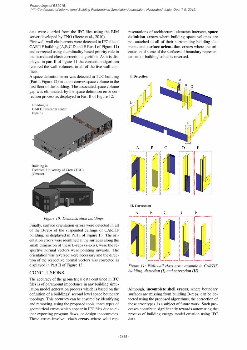
data were queried from the IFC files using the BIMserver developed by TNO (Beetz et al., 2010).Five wall-wall clash errors were detected in IFC file ofCARTIF building (A,B,C,D and E Part I of Figure 11)and corrected using a cardinality based priority rule inthe introduced clash correction algorithm. As it is dis-played in part II of figure 11 the correction algorithmrestored the wall volumes, in all of the five wall con-flicts.A space definition error was detected in TUC building(Part I, Figure 12) in a non-convex space volume in thefirst floor of the building. The associated space volumegap was eliminated, by the space definition error cor-rection process as displayed in Part II of Figure 12.
Building inTechnical University of Crete (TUC)(Greece)
Building inCARTIF research center(Spain)
Figure 10: Demonstration buildings.
Finally, surface orientation errors were detected in allof the B-reps of the suspended ceilings of CARTIFbuilding, as displayed in Part I of Figure 13. The ori-entation errors were identified at the surfaces along thesmall dimension of these B-reps (z-axis), were the re-spective normal vectors were pointing inwards. Theorientation was reversed were necessary and the direc-tion of the respective normal vectors was corrected asdisplayed in Part II of Figure 13.
CONCLUSIONSThe accuracy of the geometrical data contained in IFCfiles is of paramount importance in any building simu-lation model generation process which is based on thedefinition of a buildings’ second level space boundarytopology. This accuracy can be ensured by identifyingand removing, using the proposed tools, three types ofgeometrical errors which appear in IFC files due to ei-ther exporting program flaws, or design inaccuracies.These errors involve: clash errors where solid rep-
resentations of architectural elements intersect, spacedefinition errors where building space volumes arenot attached to all of their surrounding building ele-ments and surface orientation errors where the ori-entation of some of the surfaces of boundary represen-tations of building solids is reversed.
I. Detection
II. Correction
Figure 11: Wall-wall class error example in CARTIFbuilding: detection (I) and correction (II).
Although, incomplete shell errors, where boundarysurfaces are missing from building B-reps, can be de-tected using the proposed algorithms, the correction ofthese error types, is a subject of future work. Such pro-cesses contribute significantly towards automating theprocess of building energy model creation using IFCdata.
Proceedings of BS2015: 14th Conference of International Building Performance Simulation Association, Hyderabad, India, Dec. 7-9, 2015.
- 2188 -

I. Detection
II. Correction
Figure 12: Space definition error example in TUCbuilding: detection (I) and correction (II).
I. Detection II. Correction
Figure 13: Surface orientation error example in CAR-TIF building: detection (I) and correction (II).
ACKNOWLEDGMENTSThis research has been partially funded by the Euro-pean Commission: FP7-ICT-2011-6, ICT Systems for
Energy Efficiency #288409 (BaaS) and Innovative de-sign tools for refurbishing of buildings at district levelH2020-EeB-05-2015 #680676 (Opteemal).
REFERENCESBarequet, G., Duncan, C. A., and Kumar, S. 1998.
RSVP: A geometric toolkit for controlled repair ofsolid models. IEEE Trans. on Visualization andComputer Graphics, 4(2):162–177.
Barequet, G. and Kumar, S. 1997. Repairing CADmodels. In Visualization’97, pages 363–370. IEEE.
Bazjanac, V. 2010. Space boundary requirements formodeling of building geometry for energy and otherperformance simulation. In 27th CIB W78 Interna-tional Conference, Cairo, Egypt.
Beetz, J., Van Berlo, L., de Laat, R., and Van denHelm, P. 2010. BIMserver. org - an open sourceIFC model server. In 27th CIB W78 InternationalConference, Cairo, Egypt.
Jackson, D. 1995. Boundary representation modellingwith local tolerances. In 3rd ACM symposium onSolid modeling and applications, pages 247–254.ACM.
Ju, T. 2004. Robust repair of polygonal models. InACM Transactions on Graphics (TOG), volume 23,pages 888–895. ACM.
Khemlani, L. 2002. Solibri model checker.CADENCE-AUSTIN, pages 32–34.
Klosowski, J. T., Held, M., Mitchell, J. S., Sowizral,H., and Zikan, K. 1998. Efficient collision detec-tion using bounding volume hierarchies of k-dops.IEEE Trans. on Visualization and Computer Graph-ics, 4(1):21–36.
TEKLA 2014. Model checker suite. ”http://teklastructures.support.tekla.com/190/en/ext_model_checker_suite”.
Thibault, W. and Naylor, B. 1987. Set operations onpolyhedra using binary space partitioning trees. In14th annual conference on Computer graphics andinteractive techniques, volume 21, pages 153–162.ACM.
ISO-16739 2013. ISO 16739: Industry founda-tion classes (IFC) for data sharing in the construc-tion and facility management industries. EuropeanCommittee for Standardization (CEN), Brussels.
van den Helm, P., Bohms, M., and van Berlo, L. 2010.IFC-based clash detection for the open-source bim-server. In Int. Conference in Computing in civil andbuilding engineering, volume 30, pages 181–187,Nottingham, UK.
Vatti, B. 1992. A generic solution to polygon clipping.Communications of the ACM, 35(7):56–63.
Proceedings of BS2015: 14th Conference of International Building Performance Simulation Association, Hyderabad, India, Dec. 7-9, 2015.
- 2189 -