Embed Size (px)
Citation preview
1
Detection of Stator Winding Inter-turn Short Circuit
In Induction Motor Using Vibration Specified Harmonic Amplitude
Seyed Abolfazl Mortazavizadeh a, Abolfazl Vahedi b*and Alireza Zohouri c
a,b,c Special Machines & Drive Laboratory, Department of Electrical Engineering, Iran University of Science & Technology
* Corresponding author e-mail: [email protected]
Abstract
Vibration analysis is one of the most common tools in condition monitoring and detecting faults in electrical machines. There are several standards to monitor the machines condition and discern unusual situation in electrical machines by this technique. Current standards that are being used for fault diagnosis in electrical machines by vibration analysis mostly deal with increases in overall vibration amplitude in faulty conditions. As Inter-turn in motor or generator stator fault doesn’t affect overall vibration and just increase several frequencies that will be introduced in this paper, these standards cannot detect stator inter-turn. The author suggests that Pursuing of special frequencies is best way to detect inter-turn in machines by vibration technique instead of using current standards for detecting the mentioned fault. Finally will be shown vibration spectrum in an asynchronous motor in both healthy and stator winding inter-turned situation and compared the amplitude of introduced frequencies in that experimental object.
Keywords: Condition monitoring, Vibration, Standard, Inter-turn, Fault diagnosis.
1. Introduction
Induction motors are vital components in many industrial applications. Although they carry some important advantages such as robustness, reliability and simplicity of structure, they do occasionally fail, which may be inherent in the machine itself or caused by operating conditions [1]. Despite the fact that induction machines are reliable, they are subjected to some undesirable stresses, causing them some faults resulting in failures [2], [3], [4].
Induction motor is subjected to many different types of faults [5]. A recent reliability paper [6] described and listed the distribution of IM faults as follows: bearing (69%), stator windings (21%), rotor bar (7%), and shaft/coupling (3%). According to this static distribution, the importance of stator faults had inspired several academic and industrial researches. The times passed between the appearances of an inter-turn short-circuit and the final breakdown of the motor is available.
2nd International Conference on Acoustics & Vibration (ISAV2012), Tehran, Iran, 26-27 Dec. 2012
Studies demonstrated that a faulty motor can tolerate several start up and stop cycles with rated load operation. However, other cases exist where the complete breakdown occurs almost immediately the inter-turn short circuit is detected [7]. Many techniques have been proposed to detect the stator inter-turn faults over the last three decades. Techniques based on the time domain analysis of induction motor currents and voltages basically analyze their sequence components [8].
Vibration analysis is one of the most common techniques for electrical machinery. There are several standards in vibration method. VDI 2056 & ISO 10816 families are well known in industry [9], [10]. Commonly they measure overall amplitude of several parts of electrical machinery.
2. Cause of Stresses in Stator
The stator is subjected to various stresses such as thermal, electrical, mechanical, and environmental [11], [12], [13], [14], [15], [16], [17] which severely affects the stator condition leading to faults [4]. Deterioration of winding insulation usually begins as an inter-turn fault involving a few turns of the winding. The fault current, which is the order of twice locked-rotor current, causes severe localized heating and the fault rapidly spreads to a larger section of the winding [18] .
The majority of these faults are caused because of a combination of various stresses acting on the stator, which can be classified as follows [19]:
2.1 Thermal Stresses These stresses might occur due to thermal aging and thermal overloading. As a thumb rule,
for every 10 C increase in temperature, the insulation life gets halved due to thermal aging. Unless the operating temperature is extremely high, the normal effect of thermal aging is to render the insulation system vulnerable to other influencing factors or stresses that actually cause the failure [11]. If the insulation system loses its physical integrity, it fails to resist the other dielectric, mechanical, and environmental stresses. The winding failure will occur irrespective of the degree of thermal aging, if any of the above mentioned stresses becomes severe. Thermal overloading can occur due to the applied voltage variations, unbalanced phase voltage, cycling overloading, obstructed ventilation, higher ambient temperature, etc. As a thumb rule, for every 3.5% voltage unbalance per phase, the winding temperature increases by 25% in the phase with the highest current [11].
2.2 Electrical Stresses The electrical stresses leading to winding failures can be classified into dielectric, tracking,
corona, and transient voltage conditions. The definite relationship between insulation life and the voltage stresses applied to the insulating materials has to be taken into consideration during selecting the materials and establishing the coil designs for adequate design life. These stresses can be classified into: 1) phase-to-phase, 2) turn-to-turn, and 3) turn-to-ground.
Stress
Thermal Mechanical Electrical Environmental
2nd International Conference on Acoustics & Vibration (ISAV2012), Tehran, Iran, 26-27 Dec. 2012
3
2.3 Mechanical Stresses These stresses might be produced from coil movement and rotor striking the stator.The force
on the coils due to the stator winding current is maximum during the starting cycle and causing the coils to vibrate at twice the line frequency with movement both in the radial and tangential directions. This coil movement can cause damage to the coil insulation, loosen the top sticks, and cause damage to the copper conductors. The rotor can strike the stator due to a number of reasons like bearing failures, shaft deflection, rotor-to-stator misalignment, etc.
2.4 Environmental Stresses/Contamination: The presence of foreign material could cause various ill effects on the functioning of the
motor such as reduction in heat dissipation (which will increase operating temperature thereby reducing insulation life), premature bearing failure because of high-localized stresses, and breakdown of the insulation system (causing shorts and grounds). [5]
The inter turns short circuit (ITSC) fault in a stator winding is one of the stator faults which had recently attracted considerable research and great industrial interest, since its early and efficient diagnosis paves the way to avoiding more severe stator faults. In fact, if a short circuit of a few turns is undetected the fault will be spreading out causing critical insulation breakdown (by the increase of the temperature) and finally leading to phase-ground or phase-phase faults in a short time and thus conducts to the permanent damage of the motor. [20]
There are many ways to detect mechanical and electrical problems in induction motors, either directly or indirectly, such as vibration analysis [2], [21], motor current signature analysis (MCSA) [11] , [12] , [22] , [23] , electromagnetic field monitoring [13], chemical analysis, temperature measurability, infrared measurement, acoustic noise analysis [24], and partial discharge measurement. Among these methods, vibration analysis and current analysis are the most popular ones due to their easy measurability, high accuracy and reliability.
This paper will introduce diagnosis of inter-turn fault in stator of induction motors by analyzing stator frame vibration spectrum.
3. The Air-gap Magnetic Field Analysis
According to the fundamental of the electro-mechanics, the rotating magnetic field of asynchronous motor is rotating at the synchronizing speed 푛 = so the alternating frequency of magnetic is the same as the frequency of electric network. The magnetic poles always become to appear coupled, this makes the rotor of asynchronous motor in one rotating period bear the electromagnetic force which has double frequency of rotating magnetic field. Note that, electromagnetic force changes p times (p is number of pole pairs) when the electromagnetic pulling force rotating around, which is produced by the magnetic poles. At spatial location, the electromagnetic vibration and rotating magnetic field are synchronous; the frequency of stator electromagnetic vibration is 2푓 which is the product of the rotating magnetic field frequency (푓 푝)
and the number of pole-pairs of electromotor (2푝), and is double of the power supply frequency. The electromagnetic vibration arouse by stator abnormity. There are many different forces and interactions as a result of the power source and the
interactions between the stator and rotor. The power source is a sinusoidal voltage that varies from positive to negative peak voltage in each cycle. Many different problems either electrical or mechanical in nature can cause vibration at the same or similar frequencies. One must look closely to differentiate between the true sources of vibration. A power supply produces an electromagnetic attracting force between the stator and rotor which is at a maximum when the magnetizing current flowing in the stator is at a maximum either positive or negative at that instant in time.
2nd International Conference on Acoustics & Vibration (ISAV2012), Tehran, Iran, 26-27 Dec. 2012
4
Consequently there will be 2 peak forces during each cycle of the voltage or current wave reducing to zero at the time when the current and fundamental flux wave pass through.[13] This will result in a frequency of vibration twice the power source frequency (twice line frequency vibration). This particular vibration is extremely sensitive to the motor's foot flatness, frame and base stiffness and how consistent the air gap is between the stator and rotor, around the stator bore. It is also influenced by the eccentricity of the rotor. On 2 pole motors, the twice line frequency vibration level will appear to modulate over time due to its close relationship with 2 times rotational vibration [13].
When stator winding inter-turn short circuit fault has happened, the additional circulating current would be produced in this loop, and it will generate a MMF distribution across the air-gap, this MMF is in addition to the normal MMF. The normal MMF is rotating at synchronous speed in the direction of rotor revolution. But the MMF produced by the inter-turn fault is centered on the axis of the faulted coil, it is stationary in space, and its amplitude will be pulsated sinusoidal in time at the rated frequency. Neglecting the high order harmonics, the air-gap MMF on stator winding inter-turn short circuit fault can be represented approximately as [26]: 푓(훼, 푡) = 퐹 cos(휔푡 − 푝훼) + 퐹 cos(휔푡 + 푝훼) + 퐹 cos(3ωt − pα)
+퐹 cos 휔푡 − 푝훼 + ψ + + 퐹 cos ωt − pα + ψ + π cos(2ωt) (1) Where: p is the pair of poles number. ω=2πf = pωr = 2πpfr , ω is electrical angular frequency,
f is electrical frequency, ωr is the rotor mechanical angular frequency, fr is the rotor mechanical frequency. α is the stator mechanical space angle. ψ is generator internal active power angle.
Where the first terms in (1) will produce positive-sequence armature MMF with electric angular frequency ω, and pulsation frequency is f .The second terms in (1) will produce negative-sequence armature MMF, which electric angular frequency is ω, and pulsation frequency is f. The third terms in (1) will produce positive sequence armature MMF that its electric angular frequency is 3ω, and pulsation frequency is 3f.
Through the above mentioned analysis, the faulty characteristic information of stator electromagnetic vibration can be obtained by [25]. According to the last equation:
1) The frequency of vibration is double of the power supply frequency; 2) Cut off power supply, the electromagnetic vibration disappears immediately; the vibration
can be measured in stator frame and stator shaft bearing; 3) Vibration the rigidity of frame has relations with motor load.
4. Experimental Test
To verify the accuracy of the analysis of vibration theory which is mentioned above, this paper chooses asynchronous motor which model number is Y2-100LZ-4 to do a series of experimental tests in the special machines & drive laboratory at Iran University of Science & Technology. The following parts of this paper will priority study the influence of faulty rotor windings causes of vibration to motor. Through the experiment , the time-domain vibration signal of motor’s frame is measured when motor is at the normal condition state, two inter-turn short circuited and five inter-turn short circuited then analysis about the transformation of frequency domain is carry out also the changing regulation of vibration signal while having fault is discussed.
During the period of testing, the motor is fixed on the working table and operating with nominal voltage. The basic parameters of motor are shown in table 1. Motor with connection turn to turn is shown in Figure 2. By connecting two or more wires extracted from the stator we can have 2 or more inter-turn circuit where the multi-channel vibration signal collecting and processing equipment is Easy Viber which is manufactured by VMI Company as the data signal collecting system.
2nd International Conference on Acoustics & Vibration (ISAV2012), Tehran, Iran, 26-27 Dec. 2012
Table1. Motor Basic Parameters
Rated Voltage (v) Rated Power (hp) Frequency (Hz) Rated speed (rpm) Number of phase
380 4 50 1430 3
Number of Pole-pairs Type Rs (Ω) Rr (Ω) Weight (Kg)
2 Y2-100LZ-4 2.3 2.2 38
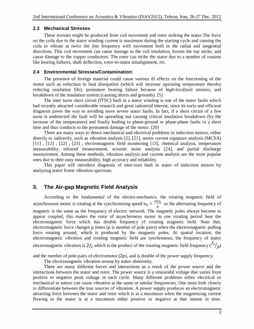
Table 2.(a) Typical zone boundry limits(ISO 10816-1) [9]
(a) (b)
Figure4. (b) The 2f & its sideband components spectrum chart of motor vibration
Table 3.Main component amplitude of motor vibration signal’s spectrum
Running state 2푓 First
sideband Second
sideband Third
sideband Fourth
sideband
Average of
sidebands Healthy 0.018 0.0026 0.0140 0.0016 0.0323 0.0126 2 ring 0.0325 0.0039 0.0155 0.0029 0.0321 0.0136 5 ring 0.1002 0.0027 0.0180 0.009 0.0403 0.0175
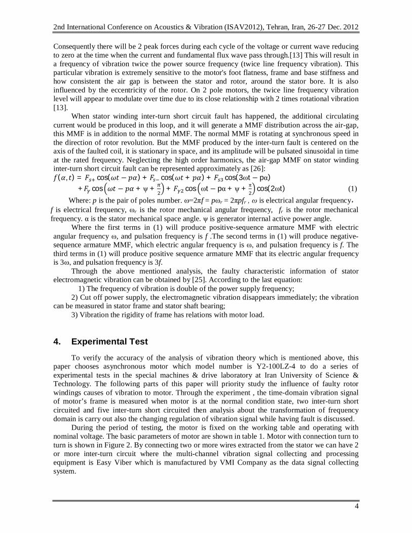
(a) (b) Figure1. Vibration signal of healthy motor: (a) Frequency domain (b) Time domain
0
0.02
0.04
0.06
0.08
0.1
0.12
Healthy motor
with 2 inter-turn
with 5 inter-turn
2f
1st sideband
2nd sideband
3rd sideband
4th sideband
2nd International Conference on Acoustics & Vibration (ISAV2012), Tehran, Iran, 26-27 Dec. 2012
4.1 The vibration experimental and spectrum analysis when the motor is operating at healthy condition The vibration signal and spectrum chart of no-load operation of healthy motor are shown in
Figure1. From Figure 1(a) & (b) the vibration signal for healthy motor operation is relatively smooth,
and also has 2푓 component and its sidebands components are so. Vibration overall amplitude (RMS) in this situation is 0.3154 mm/s and according to ISO 10816 the motor is healthy and it is true.
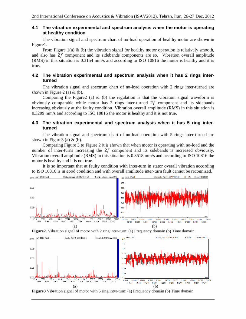
4.2 The vibration experimental and spectrum analysis when it has 2 rings inter- turned The vibration signal and spectrum chart of no-load operation with 2 rings inter-turned are
shown in Figure 2 (a) & (b). Comparing the Figure2 (a) & (b) the regulation is that the vibration signal waveform is
obviously comparable while motor has 2 rings inter-turned 2푓 component and its sidebands increasing obviously at the faulty condition. Vibration overall amplitude (RMS) in this situation is 0.3209 mm/s and according to ISO 10816 the motor is healthy and it is not true.
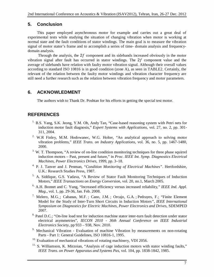
4.3 The vibration experimental and spectrum analysis when it has 5 ring inter- turned The vibration signal and spectrum chart of no-load operation with 5 rings inter-turned are
shown in Figure3 (a) & (b). Comparing Figure 3 to Figure 2 it is shown that when motor is operating with no-load and the
number of inter-turns increasing the 2푓 component and its sidebands is increased obviously. Vibration overall amplitude (RMS) in this situation is 0.3518 mm/s and according to ISO 10816 the motor is healthy and it is not true.
It is so important that at faulty condition with inter-turn in stator overall vibration according to ISO 10816 is in good condition and with overall amplitude inter-turn fault cannot be recognized.
[[[
(a) (b) Figure2. Vibration signal of motor with 2 ring inter-turn: (a) Frequency domain (b) Time domain
(a) (b)
Figure3 Vibration signal of motor with 5 ring inter-turn: (a) Frequency domain (b) Time domain
2nd International Conference on Acoustics & Vibration (ISAV2012), Tehran, Iran, 26-27 Dec. 2012
7
5. Conclusion
This paper employed asynchronous motor for example and carries out a great deal of experimental tests while studying the situation of changing vibration when motor is working at normal state and the fault conditions of stator windings. The main goal is to measure the vibration signal of motor stator’s frame and to accomplish a series of time- domain analysis and frequency-domain analysis.
Through the analysis, the 2푓 component and its sidebands increased obviously in the motor vibration signal after fault has occurred in stator windings. The 2푓 component value and the average of sidebands have relation with faulty motor vibration signal. Although their overall values according to standard ISO 10816 is in good condition (zone A), as seen in TABLE2. Certainly, the relevant of the relation between the faulty motor windings and vibration character frequency are still need a further research such as the relation between vibration frequency and motor parameters.
6. ACKNOWLEDMENT
The authors wish to Thank Dr. Poshtan for his efforts in getting the special test motor.
REFERENCES 1. B.S. Yang, S.K. Jeong, Y.M. Oh, Andy Tan, “Case-based reasoning system with Petri nets for
induction motor fault diagnosis,” Expert Systems with Applications, vol. 27, no. 2, pp. 301-311, 2004.
2. W.R Finley, M.M. Hodowanec, W.G. Holter, “An analytical approach to solving motor vibration problems,” IEEE Trans. on Industry Applications, vol. 36, no. 5, pp. 1467-1480, 2000.
3. W. T. Thompson, “A review of on-line condition monitoring techniques for three phase squirrel induction motors – Past, present and future,” in Proc. IEEE Int. Symp. Diagnostics Electrical Machines, Power Electronics Drives, 1999, pp. 3–18.
4. P. J. Tanver and J. Penman, “Condition Monitoring of Electrical Machines”. Hertfordshire, U.K.: Research Studies Press, 1987.
5. A. Siddique, G.S. Yadava, “A Review of Stator Fault Monitoring Techniques of Induction Motors,” IEEE Transactions on Energy Conversion, vol. 20, no.1, March 2005.
6. A.H. Bonnet and C. Yung, “Increased efficiency versus increased reliability,” IEEE Ind. Appl. Mag., vol. 1, pp. 29-36, Jan. Feb. 2008.
7. Melero, M.G. ; Cabanas, M.F. ; Cano, J.M. ; Orcajo, G.A. ; Pedrayes, F.; “Finite Element Model for the Study of Inter-Turn Short Circuits in Induction Motors”, IEEE International Symposium on Diagnostics for Electric Machines, Power Electronics and Drives, SDEMPED 2007.
8. Patel D.C.; “On-line load test for induction machine stator inter-turn fault detection under stator electrical asymmetries”, IECON 2010 - 36th Annual Conference on IEEE Industrial Electronics Society, pp 933 – 938, Nov. 2010.
9. Mechanical Vibration - Evaluation of machine Vibration by measurements on non-rotating Parts - Part 1: General Guidelines, ISO 10816-1, 1995.
10. Evaluation of mechanical vibrations of rotating machinery, VDI 2056. 11. S. Williamson, K. Mirzoian, “Analysis of cage induction motors with stator winding faults,”
IEEE Trans. on Power Apparatus and Systems Pas, vol. 104, pp. 1838-1842, 1985.
2nd International Conference on Acoustics & Vibration (ISAV2012), Tehran, Iran, 26-27 Dec. 2012
8
12. R.R. Schoen, T.G. Habetler, F. Kamran, “Motor bearing damage detection using stator current monitoring,” IEEE Trans. on Industry Applications, vol. 31, no. 6, pp. 1274-1279, 1995.
13. W. R. Finley, M. M. Hodowanec, W. G. Holter, “An Analytical Approach to Solving Motor Vibration Problems” Paper No. PCIC-99-20.
14. A. H. Bonnet, “Cause and analysis of stator and rotor failures in three phases squirrel-cage induction motors,” IEEE Trans. Ind. Appl., vol. 28, no. 4, pp. 921–437, Jul./Aug. 1992.
15. A. H. Bonnett and G. C. Soukpup, “Rotor failures in squirrel cage induction motors,” IEEE Trans. Ind. Appl., vol. IA-22, no. 6, pp. 1165–1173, Nov./Dec. 1986.
16. Ye Dong; “Electrical machines”, Tianjin Scientific and Technical Publishers, 1995, pp.122-262.
17. S. Nandi and H. A. Toliyat, “Condition monitoring and fault diagnosis of electrical machines – A review,” in Proc. Ind. Application. Soc., vol. 1, 1999, pp. 197–204.
18. R. M. Tallam, S.B. Lee, G.C. Stone, G.B. Kliman, J.Yoo, T.G. Habetler, and R. G. Harley, “A survey of methods for detection of stator-related faults in induction machines,” IEEE Transactions on Industrial Applications, vol. 43, no. 4, pp. 920-933, Jul./Aug. 2007.
19. Bonnett, A.K., “Cause and analysis of stator and rotor failures in 3-phase squirrel cage induction motors”, Pulp and Paper Industry Technical Conference, pp 22-42,1991
20. M. Bouzid, G. Champenois, “A novel reliable indicator of stator windings fault in induction motor extracted from the symmetrical components” , IEEE International Symposium on ,pp 489 – 495, June. 2011.
21. C. WANG , J. C. S. LAI, “Vibration Analysis of an Induction Motor”, Journal of Sound and Vibration, No. jsvi.1999.2208, pp 733-756, 1999.
22. W.T. Thomson, D. Rankin, D.G. Dorrell, “On-line current monitoring to diagnose air gap eccentricity in large three-phase induction motors-Industrial case histories,” Verify The Predictions, vol. 14, no. 4, pp. 1372-1378, 1999.
23. W.T. Thomson, M. Fenger, “Current signature analysis to detect induction motor faults,” IEEE Trans. on Industry Applications, vol. 7, pp. 26-34, 2001.
24. William R. Finley, “Noise in Induction Motors – Causes And Treatments”, IEEE transactions on industry applications, vol. 21, NO. 6, November December 1991.
25. Hongzhong Ma, Yuanyuan Ding, Lahong Li and Fen Chen, “The experimental research of vibration characteristics under induction motor windings fault”, Power Engineering Conference, 2007. IPEC 2007. International, pp 349 – 354, Dec. 2007.
26. Li Heming, Wan Shuting, Li Yonggang, Wang Aimeng, “Condition Monitoring of Generator Stator Winding Inter-Turn Short Circuit”, 2005, IEEE.


![Untitled-1 [] · Run Capacitor Stator Winding Relay Rotary Switch Rotor Start capacitor Main or Run Windin Stator Winding Main Winding Start capacitor Rotor](https://img.pdfslide.net/doc/110x75/5fc791720420d159865384b0/untitled-1-run-capacitor-stator-winding-relay-rotary-switch-rotor-start-capacitor.jpg)

![Stator Laminated stator · · 2016-11-16Winding hotspot Average winding Lowest winding Magnet Stator back iron Housing 0 1800 3600 5400 7200 9000 20 40 60 80 100 120 140 Time [secs]]](https://img.pdfslide.net/doc/110x75/5b04e5c37f8b9a6c0b8e6eee/stator-laminated-stator-hotspot-average-winding-lowest-winding-magnet-stator-back.jpg)