Embed Size (px)
Citation preview
ECNDT 2014 Dr. Johannes Vrana
Determination of an Optimal Examination Grid
for the Automated Ultrasonic Inspection of Heavy Rotor Forgings
DGZfP Committee Ultrasonic Testing
Subcommittee Automated UT
ECNDT 2014 Dr. Johannes Vrana
Automated Shaft Inspection SystemSaarschmiede, Völklingen
ECNDT 2014 Dr. Johannes Vrana
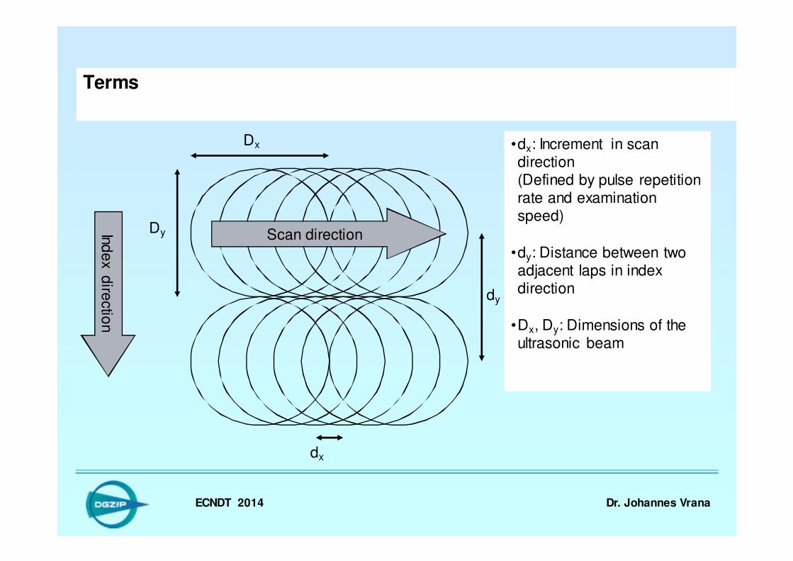
Terms
Dx
dx
dy
Dy Scan directionInd
ex
dire
ctio
n
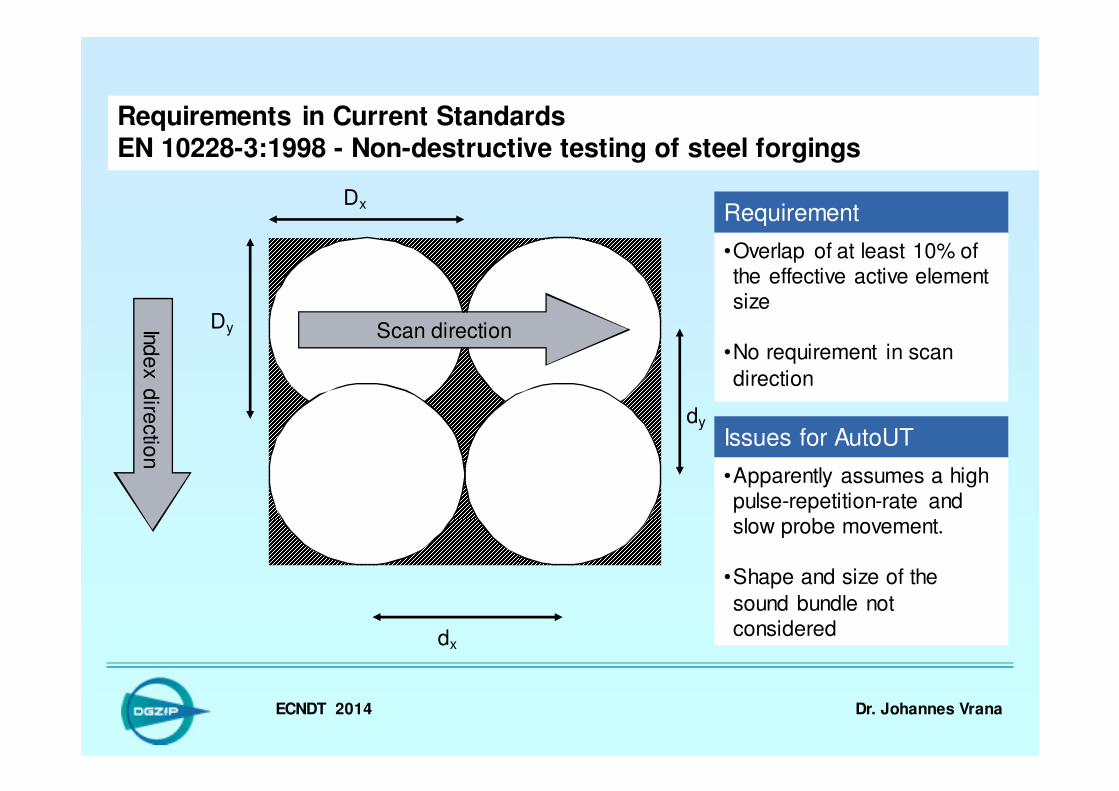
•dx: Increment in scan direction(Defined by pulse repetition rate and examination speed)
•dy: Distance between two adjacent laps in index direction
•Dx, Dy: Dimensions of the ultrasonic beam
ECNDT 2014 Dr. Johannes Vrana
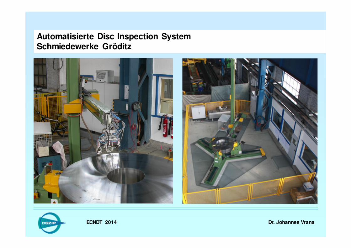
Automatisierte Disc Inspection SystemSchmiedewerke Gröditz
ECNDT 2014 Dr. Johannes Vrana
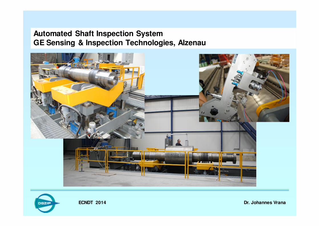
Automated Shaft Inspection SystemGE Sensing & Inspection Technologies, Alzenau

ECNDT 2014 Dr. Johannes Vrana
Automated Shaft Inspection SystemKARL DEUTSCH Prüf- und Messgerätebau GmbH + Co KG, BGH Siegen
ECNDT 2014 Dr. Johannes Vrana
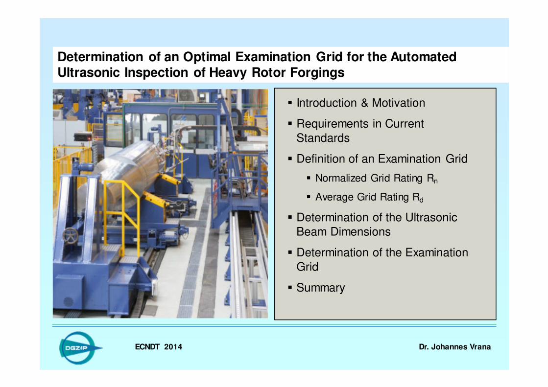
Determination of an Optimal Examination Grid for the Automated Ultrasonic Inspection of Heavy Rotor Forgings
� Introduction & Motivation
� Requirements in Current
Standards
� Definition of an Examination Grid
� Normalized Grid Rating Rn
� Average Grid Rating Rd
� Determination of the Ultrasonic
Beam Dimensions
� Determination of the Examination
Grid
� Summary
ECNDT 2014 Dr. Johannes Vrana
Determination of an Optimal Examination Grid for the Automated Ultrasonic Inspection of Heavy Rotor Forgings
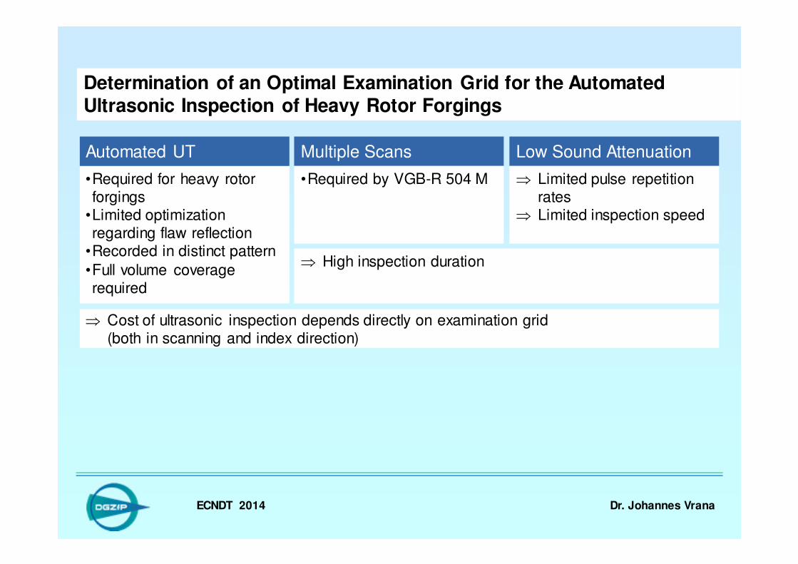
•Required for heavy rotor forgings
•Limited optimization regarding flaw reflection
•Recorded in distinct pattern
•Full volume coverage required
Automated UT Multiple Scans
•Required by VGB-R 504 M
Low Sound Attenuation
⇒ Limited pulse repetition rates
⇒ Limited inspection speed
⇒ Cost of ultrasonic inspection depends directly on examination grid(both in scanning and index direction)
⇒ High inspection duration
ECNDT 2014 Dr. Johannes Vrana
Determination of an Optimal Examination Grid for the Automated Ultrasonic Inspection of Heavy Rotor Forgings
� Introduction & Motivation
� Requirements in Current
Standards
� Definition of an Examination Grid
� Normalized Grid Rating Rn
� Average Grid Rating Rd
� Determination of the Ultrasonic
Beam Dimensions
� Determination of the Examination
Grid
� Summary
ECNDT 2014 Dr. Johannes Vrana
Requirements in Current StandardsEN 10228-3:1998 - Non-destructive testing of steel forgings
Dx
dx
dy
Dy Scan directionInd
ex
dire
ctio
n
Requirement
•Overlap of at least 10% of the effective active element size
•No requirement in scan
direction
Issues for AutoUT
•Apparently assumes a high pulse-repetition-rate and slow probe movement.
•Shape and size of the
sound bundle not considered
ECNDT 2014 Dr. Johannes Vrana
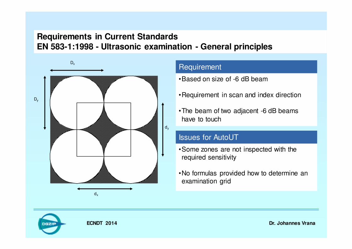
Requirements in Current StandardsEN 583-1:1998 - Ultrasonic examination - General principles
Requirement
•Based on size of -6 dB beam
•Requirement in scan and index direction
•The beam of two adjacent -6 dB beams
have to touch
Issues for AutoUT
•Some zones are not inspected with the required sensitivity
•No formulas provided how to determine an examination grid
Dx
dx
dy
Dy
ECNDT 2014 Dr. Johannes Vrana
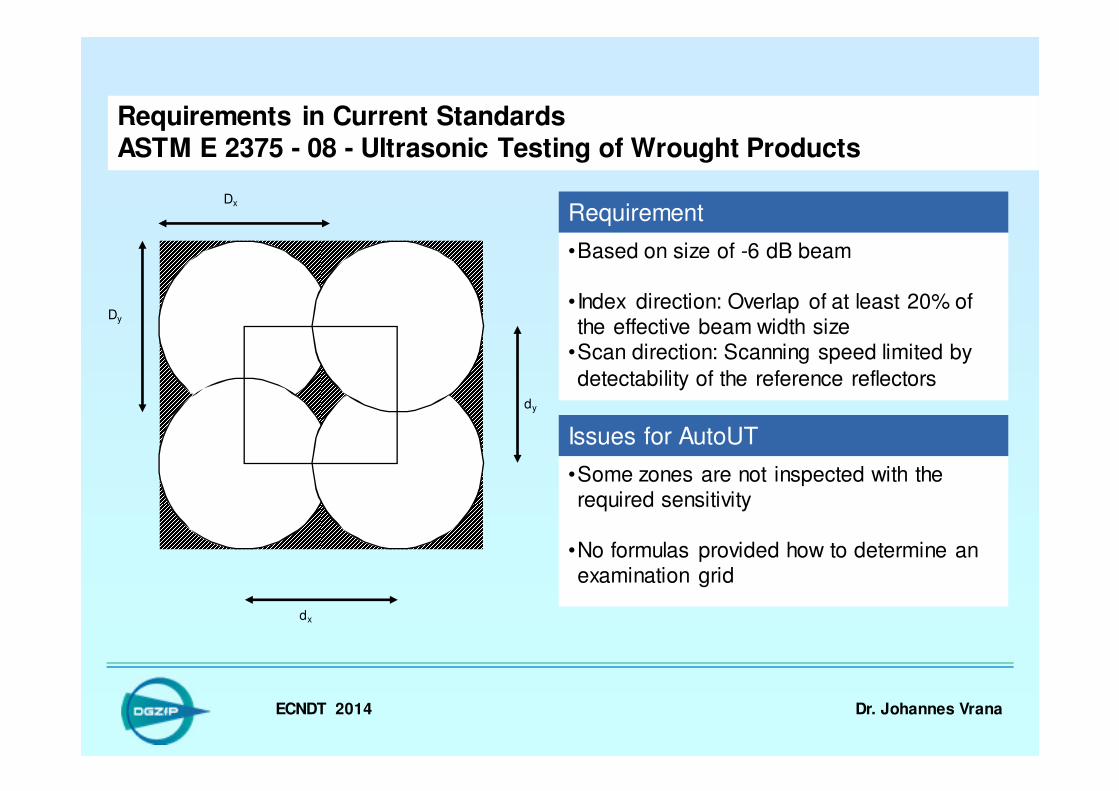
Requirements in Current StandardsASTM E 2375 - 08 - Ultrasonic Testing of Wrought Products
Requirement
•Based on size of -6 dB beam
•Index direction: Overlap of at least 20% of the effective beam width size
•Scan direction: Scanning speed limited by
detectability of the reference reflectors
Issues for AutoUT
•Some zones are not inspected with the required sensitivity
•No formulas provided how to determine an examination grid
Dx
dx
dy
Dy
ECNDT 2014 Dr. Johannes Vrana
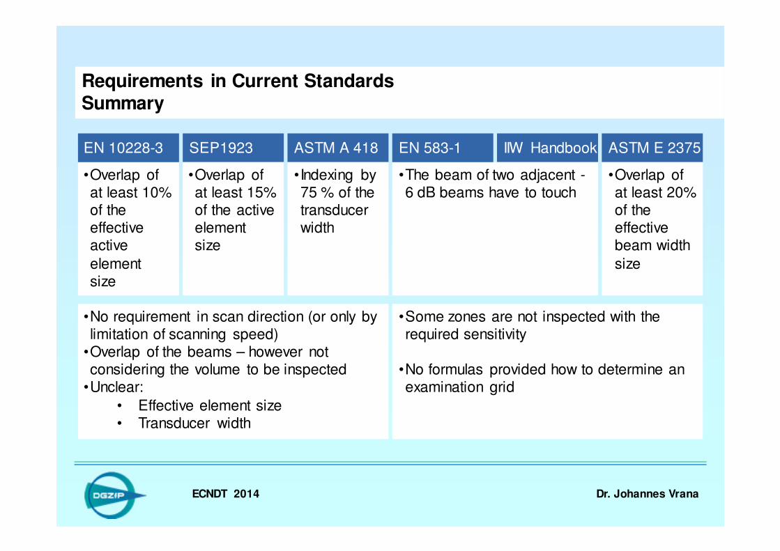
Requirements in Current StandardsSummary
•Overlap of at least 10% of the effective active
element size
EN 10228-3 SEP1923 IIW Handbook
•Overlap of at least 15% of the active element size
•The beam of two adjacent -6 dB beams have to touch
EN 583-1
•No requirement in scan direction (or only by limitation of scanning speed)
•Overlap of the beams – however not considering the volume to be inspected
•Unclear:
• Effective element size• Transducer width
•Some zones are not inspected with the required sensitivity
•No formulas provided how to determine an examination grid
ASTM E 2375
•Overlap of at least 20% of the effective beam width
size
ASTM A 418
•Indexing by 75 % of the transducer width

ECNDT 2014 Dr. Johannes Vrana
Determination of an Optimal Examination Grid for the Automated Ultrasonic Inspection of Heavy Rotor Forgings
•Required for heavy rotor forgings
•Limited optimization regarding flaw reflection
•Recorded in distinct pattern
•Full volume coverage required
Automated UT Multiple Scans
•Required by VGB-R 504 M
Low Sound Attenuation
⇒ Limited pulse repetition rates
⇒ Limited inspection speed
⇒ Cost of ultrasonic inspection depends directly on examination grid(both in scanning and index direction)
Motivation •Existing standards define examination grids for manual inspection⇒ Not simply transferable to automated
⇒ High inspection duration
⇒ Start of development of an Optimal Examination Grid for the Automated Ultrasonic Inspection
ECNDT 2014 Dr. Johannes Vrana
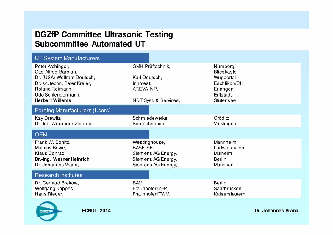
DGZfP Committee Ultrasonic TestingSubcommittee Automated UT
Peter Archinger, GMH Prüftechnik, Nürnberg Otto Alfred Barbian, Blieskastel Dr. (USA) Wolfram Deutsch, Karl Deutsch, Wuppertal
Dr. sc. techn. Peter Kreier, Innotest, Eschlikon/CHRoland Reimann, AREVA NP, Erlangen
Udo Schlengermann, Erftstadt Herbert Willems, NDT Syst. & Services, Stutensee
Kay Drewitz, Schmiedewerke, GröditzDr.-Ing. Alexander Zimmer, Saarschmiede, Völklingen
Frank W. Bonitz, Westinghouse, Mannheim Mathias Böwe, BASF SE, Ludwigshafen Klaus Conrad, Siemens AG Energy, Mülheim
Dr.-Ing. Werner Heinrich, Siemens AG Energy, Berlin Dr. Johannes Vrana, Siemens AG Energy, München
Dr. Gerhard Brekow, BAM, Berlin Wolfgang Kappes, Fraunhofer IZFP, Saarbrücken Hans Rieder, Fraunhofer ITWM, Kaiserslautern
UT System Manufacturers
Forging Manufacturers (Users)
OEM
Research Institutes
ECNDT 2014 Dr. Johannes Vrana
Determination of an Optimal Examination Grid for the Automated Ultrasonic Inspection of Heavy Rotor Forgings
� Introduction & Motivation
� Requirements in Current
Standards
� Definition of an Examination
Grid
� Normalized Grid Rating Rn
� Average Grid Rating Rd
� Determination of the Ultrasonic Beam Dimensions
� Determination of the Examination Grid
� Summary
ECNDT 2014 Dr. Johannes Vrana
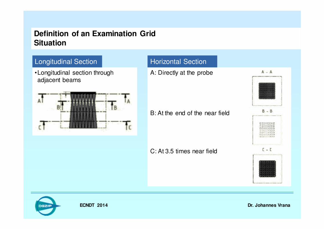
•Longitudinal section through adjacent beams
Definition of an Examination GridSituation
B: At the end of the near field
C: At 3.5 times near field
Longitudinal Section
A: Directly at the probe
Horizontal Section
ECNDT 2014 Dr. Johannes Vrana
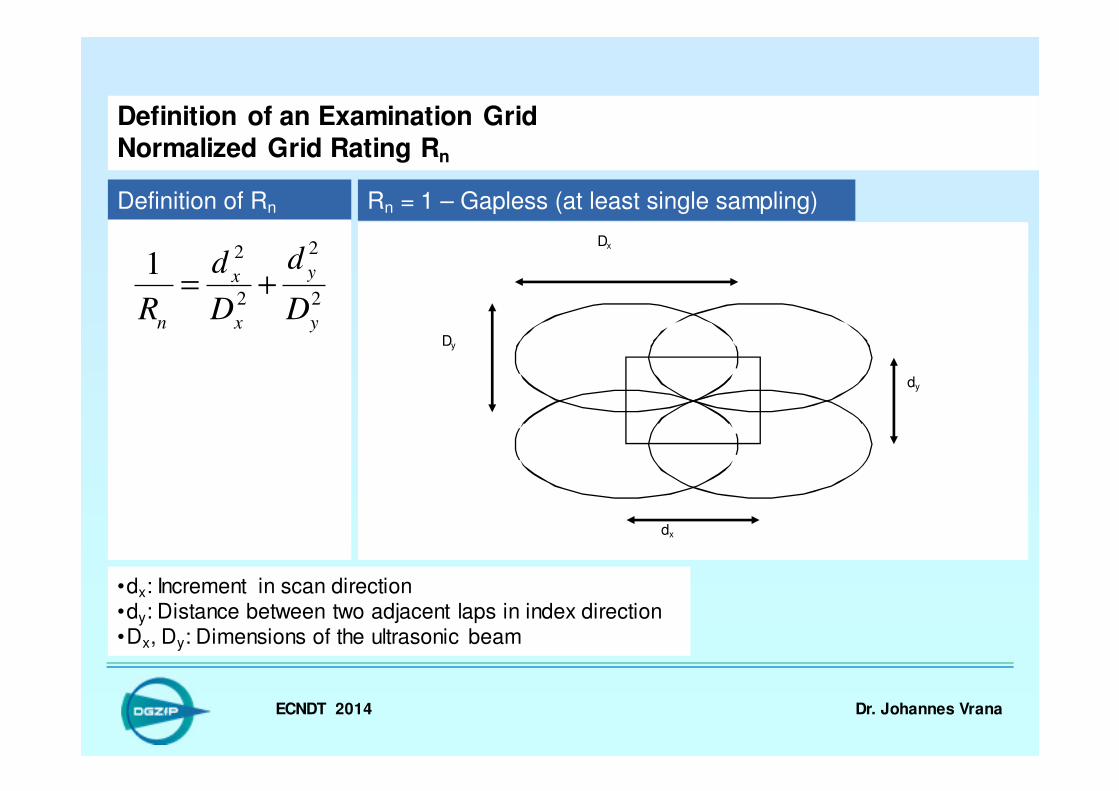
Definition of an Examination GridNormalized Grid Rating Rn
Definition of Rn
2
2
2
21
y
y
x
x
nD
d
D
d
R+=
•dx: Increment in scan direction•dy: Distance between two adjacent laps in index direction•Dx, Dy: Dimensions of the ultrasonic beam
Rn = 1 – Gapless (at least single sampling)
dx
dy
Dx
Dy

ECNDT 2014 Dr. Johannes Vrana
Definition of an Examination GridNormalized Grid Rating Rn
Definition of Rn
2
2
2
21
y
y
x
x
nD
d
D
d
R+=
•dx: Increment in scan direction•dy: Distance between two adjacent laps in index direction•Dx, Dy: Dimensions of the ultrasonic beam
Rn = 2 – At least double sampling
dx
dy
Dx
Dy

ECNDT 2014 Dr. Johannes Vrana
Definition of an Examination GridNormalized Grid Rating Rn
Definition of Rn Rn = 0,5 – Beams touching
2
2
2
21
y
y
x
x
nD
d
D
d
R+=
Rn = 1 - Gapless
Rn = 2 – Double Sampling Rn = 4 – Quadruple Sampling
0 1 2 3 4 5 6 7
Overlap:•dx: Increment in scan direction•dy: Distance between two adjacent laps in index direction•Dx, Dy: Dimensions of the ultrasonic beam
ECNDT 2014 Dr. Johannes Vrana
Determination of an Optimal Examination Grid for the Automated Ultrasonic Inspection of Heavy Rotor Forgings
� Introduction & Motivation
� Requirements in Current
Standards
� Definition of an Examination
Grid
� Normalized Grid Rating Rn
� Average Grid Rating Rd
� Determination of the Ultrasonic Beam Dimensions
� Determination of the Examination Grid
� Summary
ECNDT 2014 Dr. Johannes Vrana
4
π⋅⋅=
y
y
x
xd
d
D
d
DR
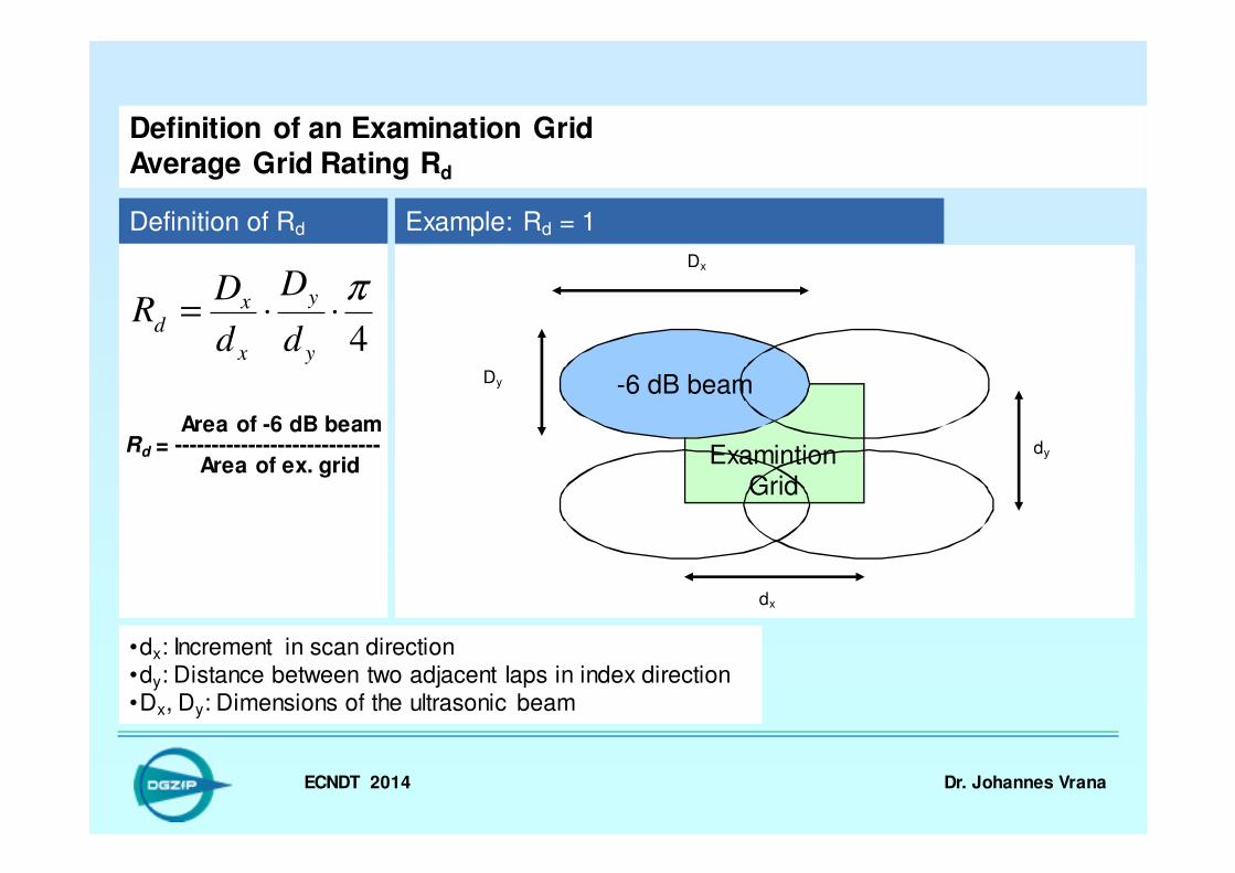
Definition of an Examination GridAverage Grid Rating Rd
Definition of Rd
•dx: Increment in scan direction•dy: Distance between two adjacent laps in index direction•Dx, Dy: Dimensions of the ultrasonic beam
Area of -6 dB beamRd = ----------------------------
Area of ex. grid
Example: Rd = 1
-6 dB beam
dx
dy
Dx
Dy
ExamintionGrid
ECNDT 2014 Dr. Johannes Vrana
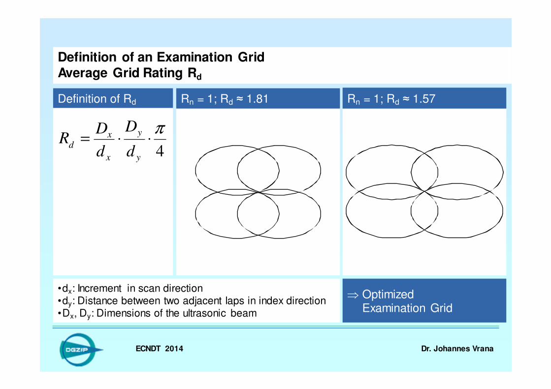
Definition of an Examination GridAverage Grid Rating Rd
Definition of Rd Rn = 1; Rd ≈ 1.81
•dx: Increment in scan direction•dy: Distance between two adjacent laps in index direction•Dx, Dy: Dimensions of the ultrasonic beam
4
π⋅⋅=
y
y
x
xd
d
D
d
DR
Rn = 1; Rd ≈ 1.57
⇒ OptimizedExamination Grid
ECNDT 2014 Dr. Johannes Vrana
4
π⋅⋅=
y
y
x
xd
d
D
d
DR
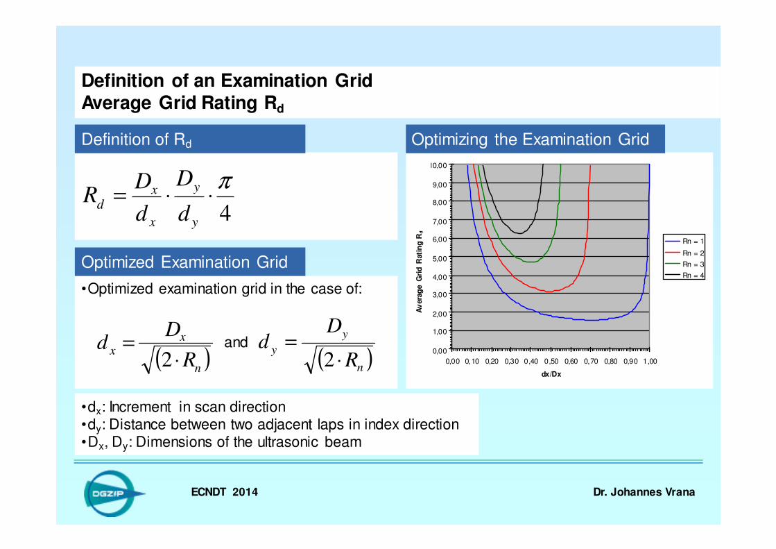
Definition of an Examination GridAverage Grid Rating Rd
Definition of Rd
•dx: Increment in scan direction•dy: Distance between two adjacent laps in index direction•Dx, Dy: Dimensions of the ultrasonic beam
•Optimized examination grid in the case of:
( )n
xx
R
Dd
⋅=
2 ( )n
y
yR
Dd
⋅=
2
Optimized Examination Grid
and
Optimizing the Examination Grid
0,00
1,00
2,00
3,00
4,00
5,00
6,00
7,00
8,00
9,00
10,00
0,00 0,10 0,20 0,30 0,40 0,50 0,60 0,70 0,80 0,90 1,00
dx/Dx
du
rch
sch
nit
tlic
he R
aste
rgü
te R
d
Rn = 1
Rn = 2
Rn = 3
Rn = 4
Av
era
ge G
rid
Rati
ng
Rd

ECNDT 2014 Dr. Johannes Vrana
Determination of an Optimal Examination Grid for the Automated Ultrasonic Inspection of Heavy Rotor Forgings
� Introduction & Motivation
� Requirements in Current
Standards
� Definition of an Examination Grid
� Normalized Grid Rating Rn
� Average Grid Rating Rd
� Determination of the Ultrasonic
Beam Dimensions
� Determination of the Examination
Grid
� Summary
ECNDT 2014 Dr. Johannes Vrana
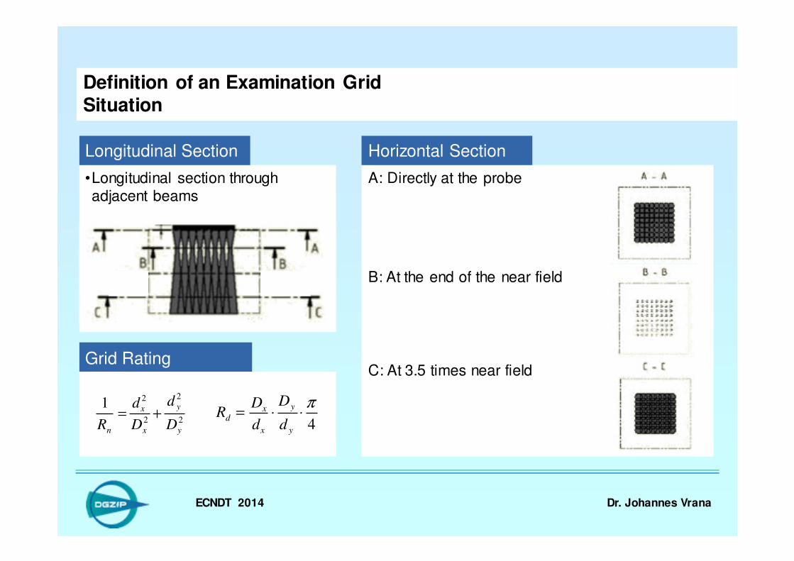
•Longitudinal section through adjacent beams
Definition of an Examination GridSituation
B: At the end of the near field
C: At 3.5 times near field
Longitudinal Section
A: Directly at the probe
Horizontal Section
Grid Rating
2
2
2
21
y
y
x
x
n D
d
D
d
R+=
4
π⋅⋅=
y
y
x
xd
d
D
d
DR
ECNDT 2014 Dr. Johannes Vrana
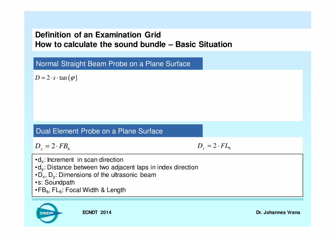
Definition of an Examination GridHow to calculate the sound bundle – Basic Situation
Normal Straight Beam Probe on a Plane Surface
( )2 tanD s ϕ= ⋅ ⋅
62
xD FB= ⋅ 62yD FL= ⋅
Dual Element Probe on a Plane Surface
•dx: Increment in scan direction•dy: Distance between two adjacent laps in index direction•Dx, Dy: Dimensions of the ultrasonic beam•s: Soundpath•FB6, FL6: Focal Width & Length
ECNDT 2014 Dr. Johannes Vrana
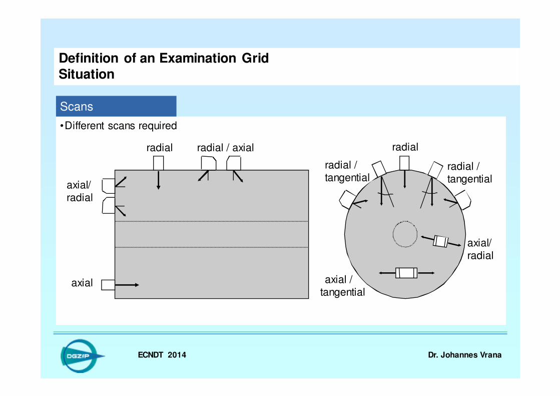
•Different scans required
Definition of an Examination GridSituation
axial
radial radial / axial
radial / tangential
radial / tangential
radial
axial / tangential
axial/ radial
axial/radial
Scans
ECNDT 2014 Dr. Johannes Vrana
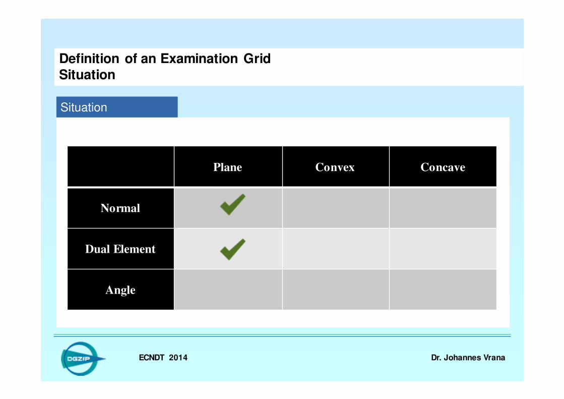
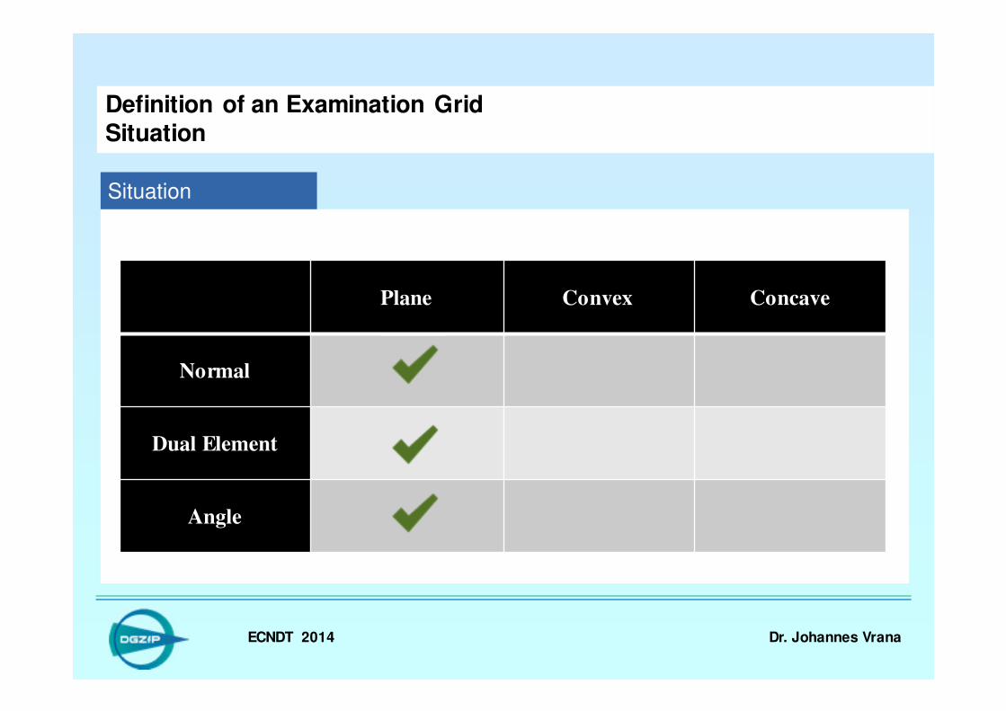
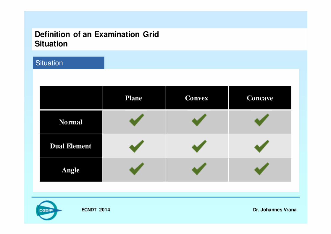
Definition of an Examination GridSituation
Situation
Plane Convex Concave
Normal
Dual Element
Angle
ECNDT 2014 Dr. Johannes Vrana
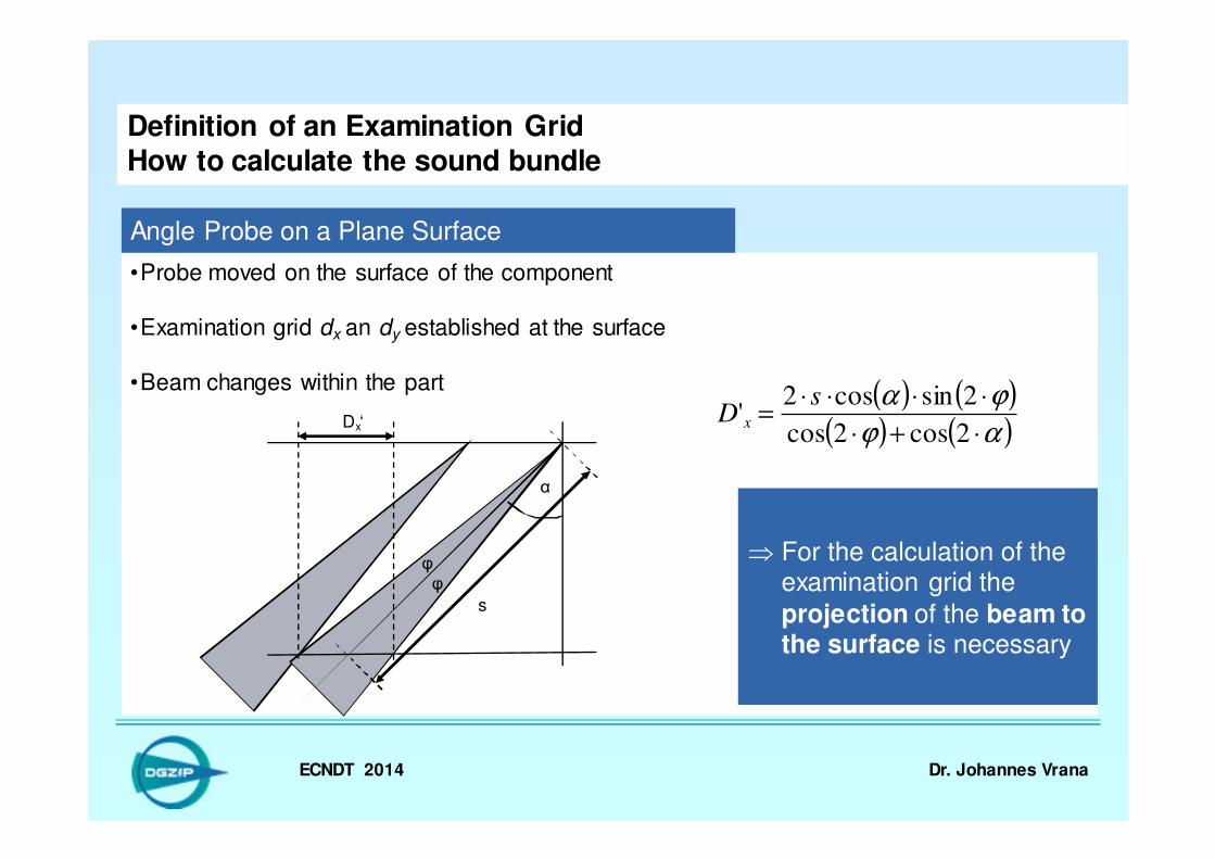
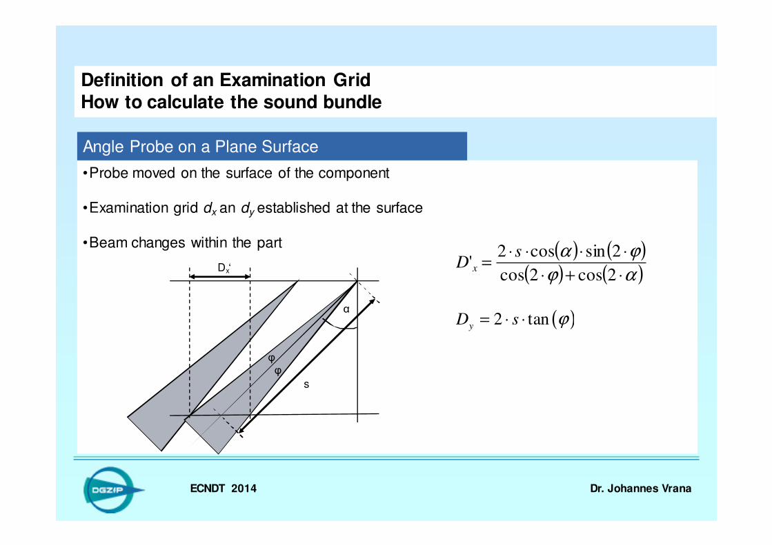
•Probe moved on the surface of the component
•Examination grid dx an dy established at the surface
•Beam changes within the part
Definition of an Examination GridHow to calculate the sound bundle
Angle Probe on a Plane Surface
Dx‘
s
α
φ φ
⇒ For the calculation of the examination grid the
projection of the beam to the surface is necessary
( ) ( )( ) ( )αϕ
ϕα
⋅+⋅
⋅⋅⋅⋅=
2cos2cos
2sincos2'
sD x
ECNDT 2014 Dr. Johannes Vrana
•Probe moved on the surface of the component
•Examination grid dx an dy established at the surface
•Beam changes within the part
Definition of an Examination GridHow to calculate the sound bundle
Angle Probe on a Plane Surface
Dx‘
s
α
φ φ
( ) ( )( ) ( )αϕ
ϕα
⋅+⋅
⋅⋅⋅⋅=
2cos2cos
2sincos2'
sD x
( )2 tany
D s ϕ= ⋅ ⋅
ECNDT 2014 Dr. Johannes Vrana
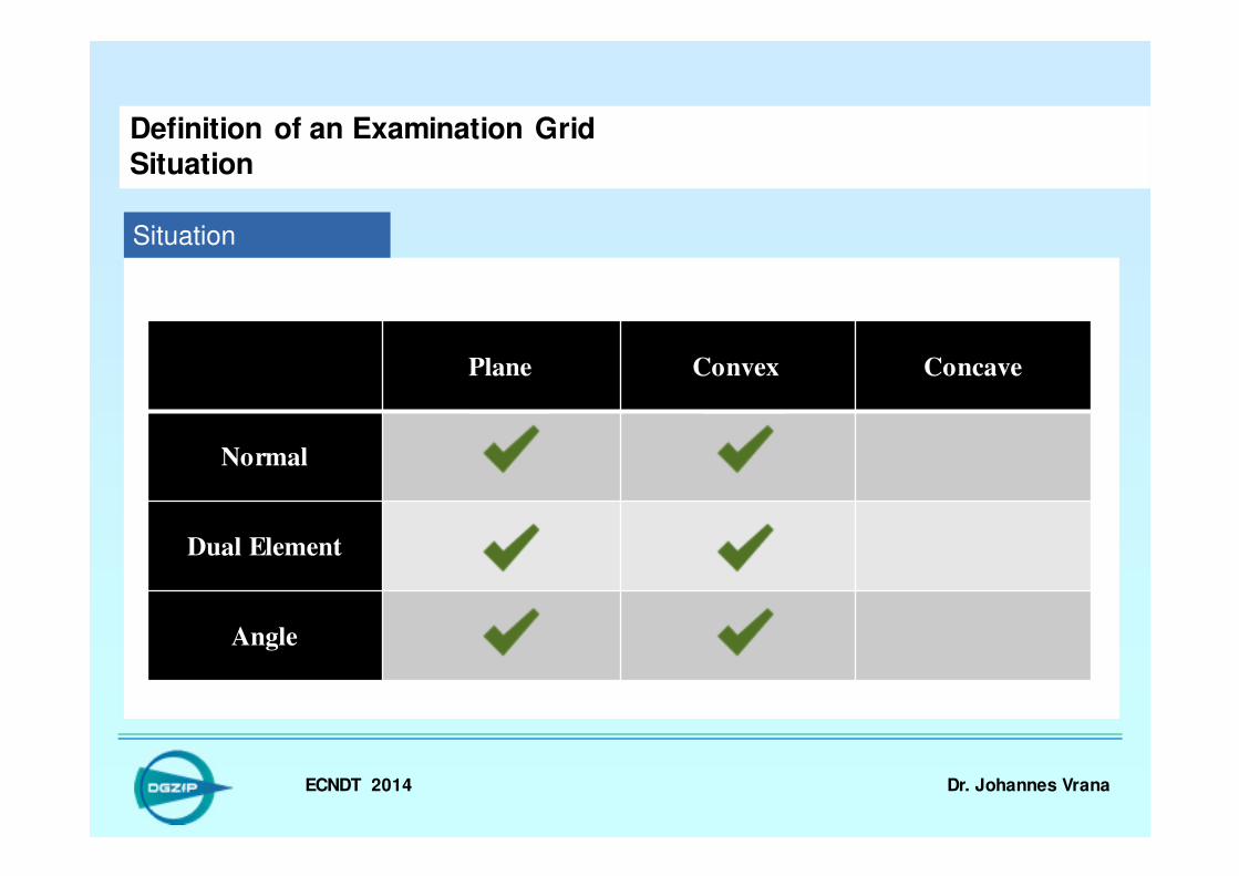
Definition of an Examination GridSituation
Situation
Plane Convex Concave
Normal
Dual Element
Angle

ECNDT 2014 Dr. Johannes Vrana
Definition of an Examination GridHow to calculate the sound bundle
Normal Straight Beam Probe on Convex Surface
( )2 tanD s ϕ= ⋅ ⋅
62
xD FB= ⋅ 62yD FL= ⋅
Dual Element Probe on Convex Surface
1
1
1
' arcsin sin( )2 180
x
DD D
D s
πϕ ϕ
= ⋅ ± ⋅ ⋅ − ⋅ °
1
1
'2
x
x
D DD
D s
⋅=
− ⋅Corrected by:
( )2 tanyD s ϕ= ⋅ ⋅
ECNDT 2014 Dr. Johannes Vrana
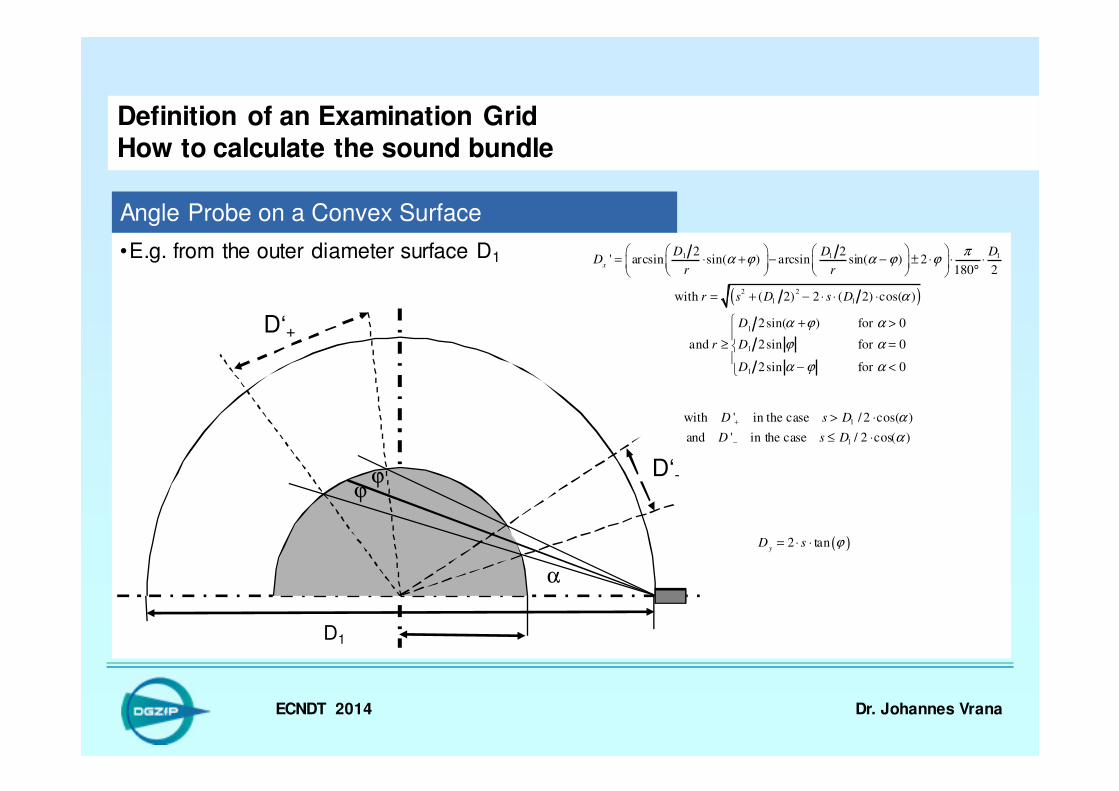
•E.g. from the outer diameter surface D1
Definition of an Examination GridHow to calculate the sound bundle
Angle Probe on a Convex Surface
D‘+
D1
D‘-ϕ
α
ϕ
( )
1 1 1
2 2
1 1
1
1
1
2 2' arcsin sin( ) arcsin sin( ) 2
180 2
with ( 2) 2 ( 2) cos( )
2sin( ) for 0
and 2sin for 0
2sin for 0
x
D D DD
r r
r s D s D
D
r D
D
πα ϕ α ϕ ϕ
α
α ϕ α
ϕ α
α ϕ α
= ⋅ + − − ± ⋅ ⋅ ⋅
°
= + − ⋅ ⋅ ⋅
+ >
≥ =
− <
1
1
' in the case /2 cos( )
and ' in the case
wit
/ 2 cos( )
h D s D
D s D
α
α
+
−
> ⋅
≤ ⋅
( )2 tany
D s ϕ= ⋅ ⋅
ECNDT 2014 Dr. Johannes Vrana
Definition of an Examination GridSituation
Situation
Plane Convex Concave
Normal
Dual Element
Angle
ECNDT 2014 Dr. Johannes Vrana
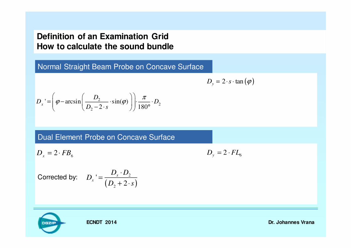
Definition of an Examination GridHow to calculate the sound bundle
Normal Straight Beam Probe on Concave Surface
62
xD FB= ⋅ 62yD FL= ⋅
Dual Element Probe on Concave Surface
Corrected by:
( )2 tanyD s ϕ= ⋅ ⋅
22
2
' arcsin sin( )2 180
x
DD D
D s
πϕ ϕ
= − ⋅ ⋅ ⋅ − ⋅ °
( )2
2
'2
x
x
D DD
D s
⋅=
+ ⋅
ECNDT 2014 Dr. Johannes Vrana
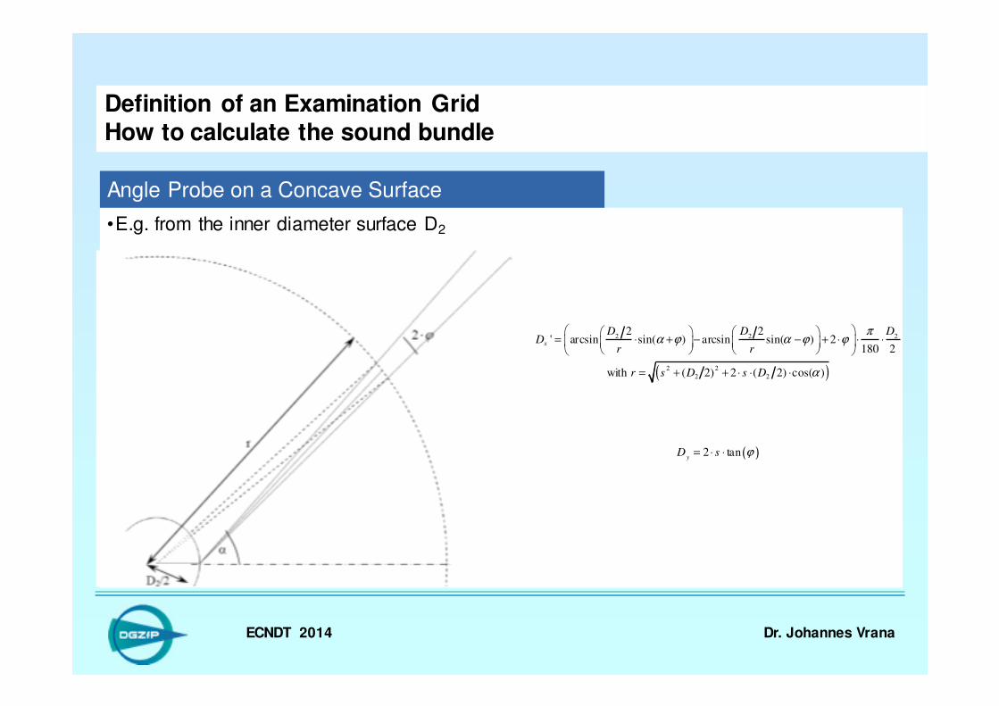
•E.g. from the inner diameter surface D2
Definition of an Examination GridHow to calculate the sound bundle
Angle Probe on a Concave Surface
( )2 tany
D s ϕ= ⋅ ⋅
( )
2 2 2
2 2
2 2
2 2' arcsin sin( ) arcsin sin( ) 2
180 2
with ( 2) 2 ( 2) cos( )
x
D D DD
r r
r s D s D
πα ϕ α ϕ ϕ
α
= ⋅ + − − + ⋅ ⋅ ⋅
= + + ⋅ ⋅ ⋅
ECNDT 2014 Dr. Johannes Vrana
Definition of an Examination GridSituation
Situation
Plane Convex Concave
Normal
Dual Element
Angle
ECNDT 2014 Dr. Johannes Vrana
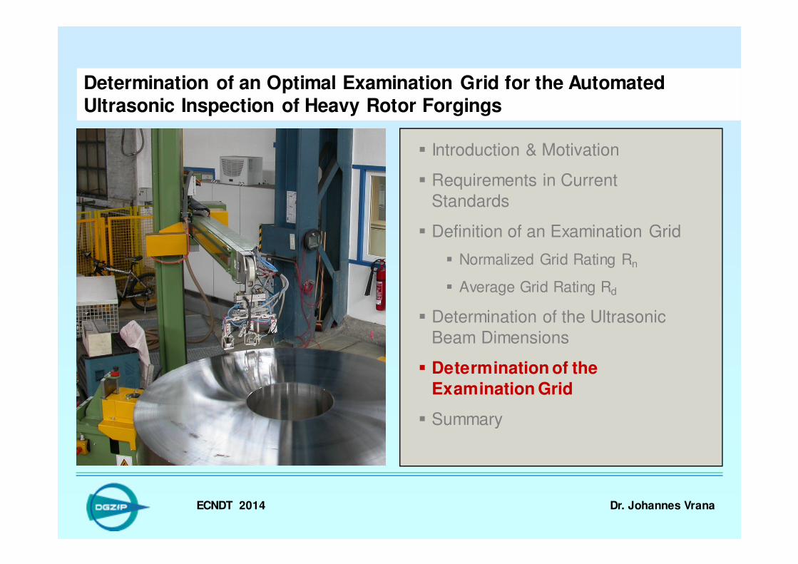
Determination of an Optimal Examination Grid for the Automated Ultrasonic Inspection of Heavy Rotor Forgings
� Introduction & Motivation
� Requirements in Current
Standards
� Definition of an Examination Grid
� Normalized Grid Rating Rn
� Average Grid Rating Rd
� Determination of the Ultrasonic
Beam Dimensions
� Determination of the
Examination Grid
� Summary
ECNDT 2014 Dr. Johannes Vrana
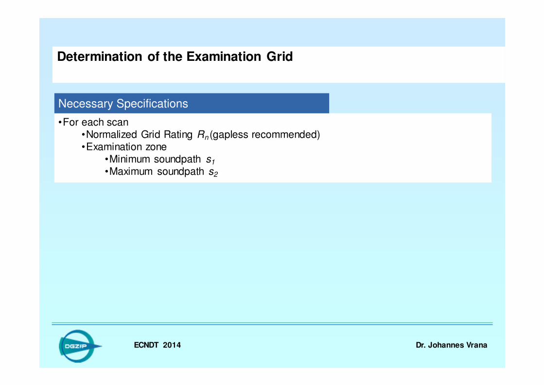
•For each scan•Normalized Grid Rating Rn (gapless recommended)•Examination zone
•Minimum soundpath s1
•Maximum soundpath s2
Determination of the Examination Grid
Necessary Specifications
ECNDT 2014 Dr. Johannes Vrana
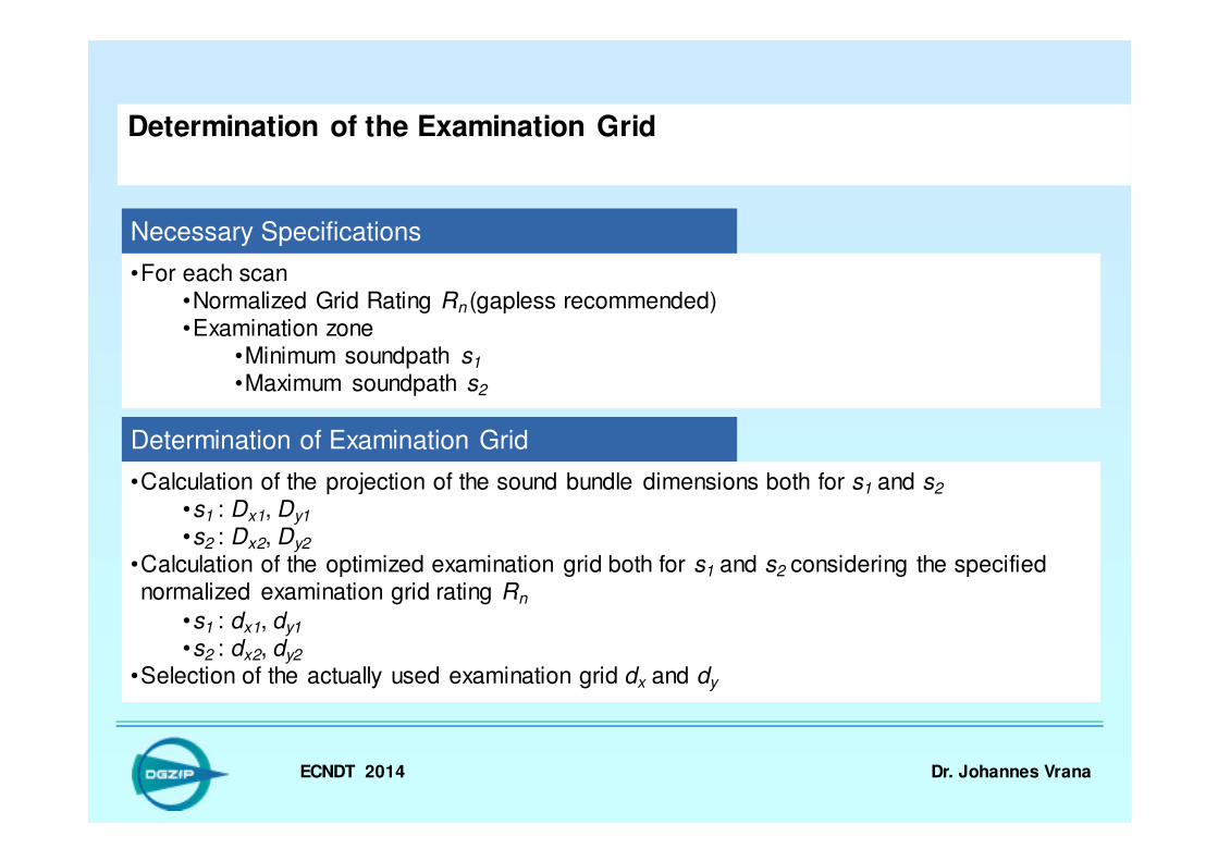
•For each scan•Normalized Grid Rating Rn (gapless recommended)•Examination zone
•Minimum soundpath s1
•Maximum soundpath s2
Determination of the Examination Grid
Necessary Specifications
Determination of Examination Grid
•Calculation of the projection of the sound bundle dimensions both for s1 and s2
•s1 : Dx1, Dy1
•s2 : Dx2, Dy2
•Calculation of the optimized examination grid both for s1 and s2 considering the specified normalized examination grid rating Rn
•s1 : dx1, dy1
•s2 : dx2, dy2
•Selection of the actually used examination grid dx and dy

ECNDT 2014 Dr. Johannes Vrana
•Calculation of the projection of the sound bundle dimensions both for s1 and s2
•s1 : Dx1, Dy1
•s2 : Dx2, Dy2
•Calculation of the optimized examination grid both for s1 and s2 considering the specified normalized examination grid rating Rn
•s1 : dx1, dy1
•s2 : dx2, dy2
•Selection of the actually used examination grid dx and dy
Determination of the Examination Grid
Determination of Examination Grid
Check of Examination Grid
•OK if both selected values are not bigger than the calculated values•dx vs. dx1, dx2
•dy vs. dy1, dy2
•Otherwise needs to be tested by calculating Rn using dx and dy for both Dx1, Dy1 and Dx2, Dy2
ECNDT 2014 Dr. Johannes Vrana
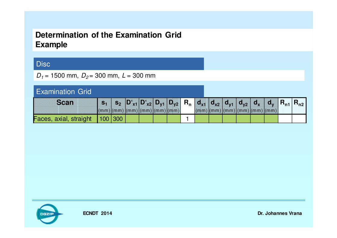
Scan s1 s2 D‘x1 D‘x2 Dy1 Dy2 Rn dx1 dx2 dy1 dy2 dx dy Rn1 Rn2
(mm) (mm) (mm) (mm) (mm) (mm) (mm) (mm) (mm) (mm) (mm) (mm)
Faces, axial, straight 100 300 1
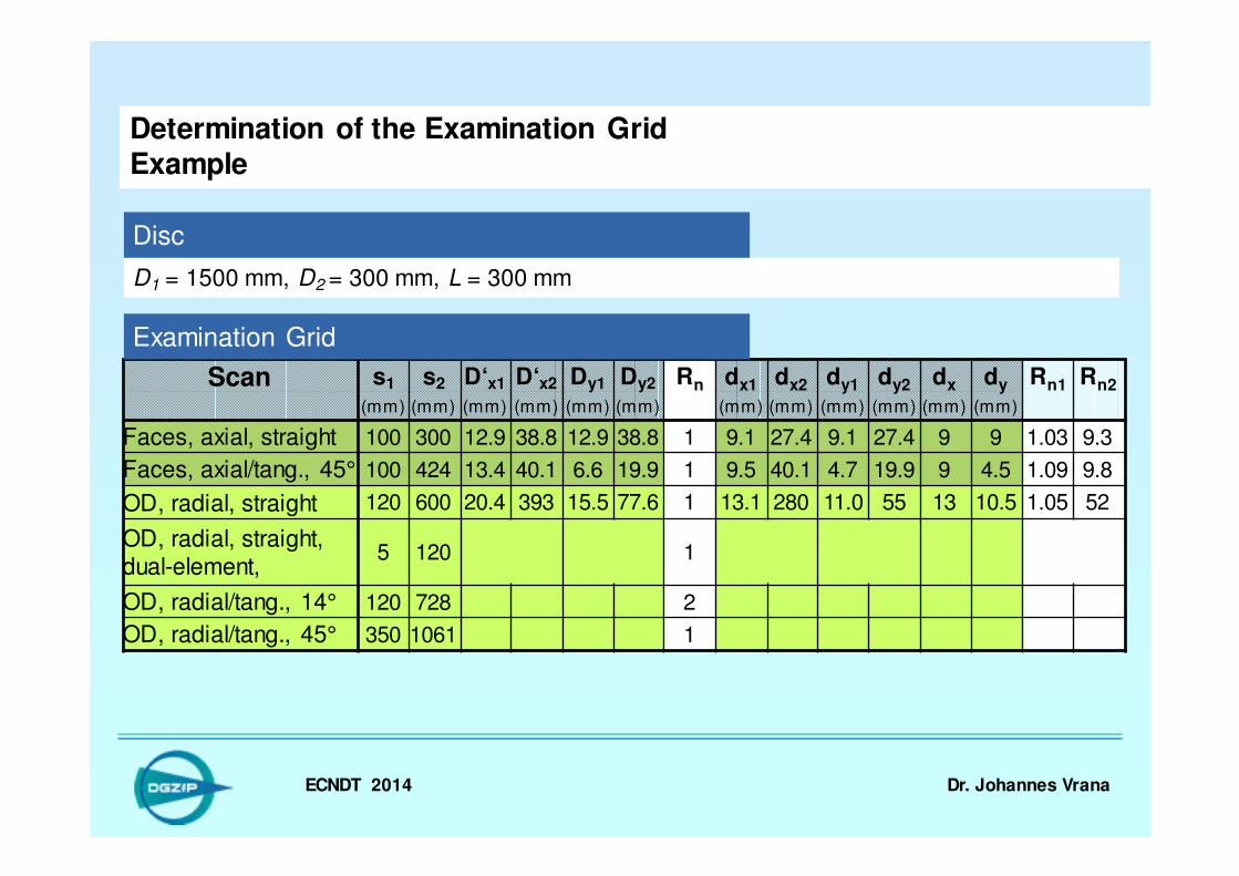
D1 = 1500 mm, D2 = 300 mm, L = 300 mm
°
Determination of the Examination GridExample
Disc
Examination Grid

ECNDT 2014 Dr. Johannes Vrana
Scan s1 s2 D‘x1 D‘x2 Dy1 Dy2 Rn dx1 dx2 dy1 dy2 dx dy Rn1 Rn2
(mm) (mm) (mm) (mm) (mm) (mm) (mm) (mm) (mm) (mm) (mm) (mm)
Faces, axial, straight 100 300 12.9 38.8 12.9 38.8 1
D1 = 1500 mm, D2 = 300 mm, L = 300 mm
°
Determination of the Examination GridExample
Disc
Examination Grid
ECNDT 2014 Dr. Johannes Vrana
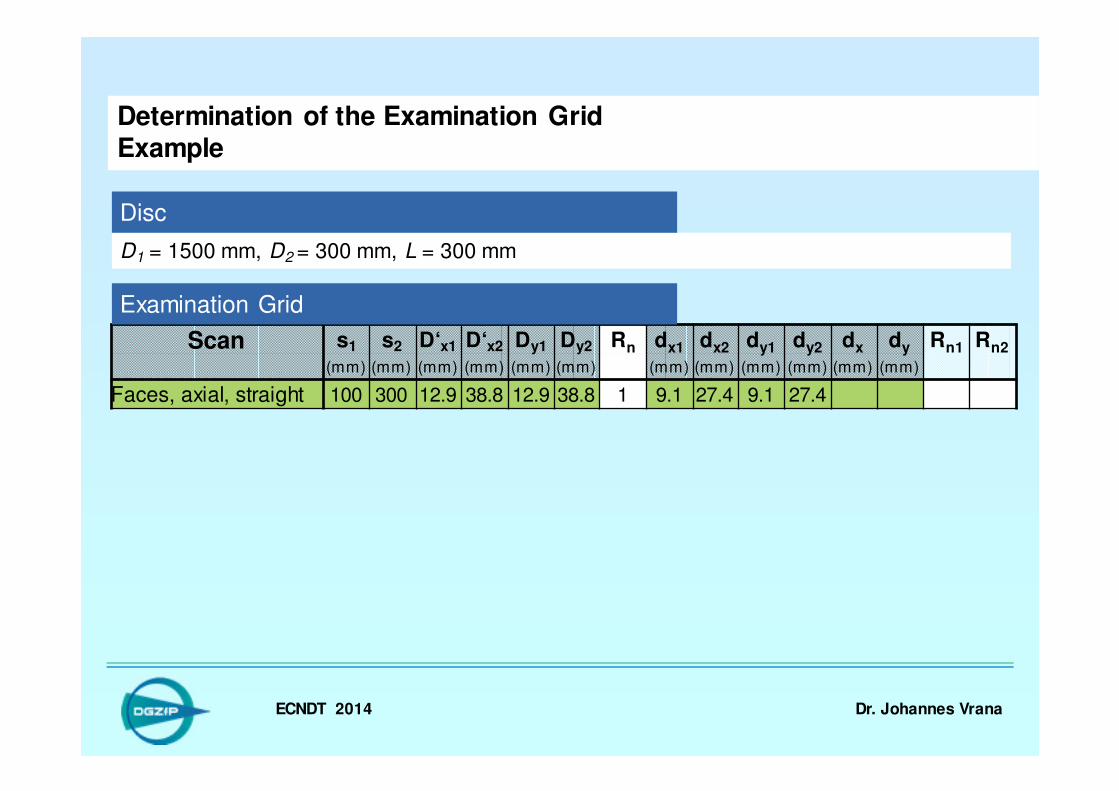
Scan s1 s2 D‘x1 D‘x2 Dy1 Dy2 Rn dx1 dx2 dy1 dy2 dx dy Rn1 Rn2
(mm) (mm) (mm) (mm) (mm) (mm) (mm) (mm) (mm) (mm) (mm) (mm)
Faces, axial, straight 100 300 12.9 38.8 12.9 38.8 1 9.1 27.4 9.1 27.4
D1 = 1500 mm, D2 = 300 mm, L = 300 mm
°
Determination of the Examination GridExample
Disc
Examination Grid

ECNDT 2014 Dr. Johannes Vrana
Scan s1 s2 D‘x1 D‘x2 Dy1 Dy2 Rn dx1 dx2 dy1 dy2 dx dy Rn1 Rn2
(mm) (mm) (mm) (mm) (mm) (mm) (mm) (mm) (mm) (mm) (mm) (mm)
Faces, axial, straight 100 300 12.9 38.8 12.9 38.8 1 9.1 27.4 9.1 27.4 9 9
D1 = 1500 mm, D2 = 300 mm, L = 300 mm
°
Determination of the Examination GridExample
Disc
Examination Grid

ECNDT 2014 Dr. Johannes Vrana
Scan s1 s2 D‘x1 D‘x2 Dy1 Dy2 Rn dx1 dx2 dy1 dy2 dx dy Rn1 Rn2
(mm) (mm) (mm) (mm) (mm) (mm) (mm) (mm) (mm) (mm) (mm) (mm)
Faces, axial, straight 100 300 12.9 38.8 12.9 38.8 1 9.1 27.4 9.1 27.4 9 9 1.03 9.3
D1 = 1500 mm, D2 = 300 mm, L = 300 mm
°
Determination of the Examination GridExample
Disc
Examination Grid
ECNDT 2014 Dr. Johannes Vrana
Scan s1 s2 D‘x1 D‘x2 Dy1 Dy2 Rn dx1 dx2 dy1 dy2 dx dy Rn1 Rn2
(mm) (mm) (mm) (mm) (mm) (mm) (mm) (mm) (mm) (mm) (mm) (mm)
Faces, axial, straight 100 300 12.9 38.8 12.9 38.8 1 9.1 27.4 9.1 27.4 9 9 1.03 9.3
Faces, axial/tang., 45° 100 424 13.4 40.1 6.6 19.9 1 9.5 40.1 4.7 19.9 9 4.5 1.09 9.8
OD, radial, straight 120 600 20.4 393 15.5 77.6 1 13.1 280 11.0 55 13 10.5 1.05 52
OD, radial, straight, dual-element,
5 120 1
OD, radial/tang., 14° 120 728 2
OD, radial/tang., 45° 350 1061 1
D1 = 1500 mm, D2 = 300 mm, L = 300 mm
°
Determination of the Examination GridExample
Disc
Examination Grid
ECNDT 2014 Dr. Johannes Vrana
Scan s1 s2 D‘x1 D‘x2 Dy1 Dy2 Rn dx1 dx2 dy1 dy2 dx dy Rn1 Rn2
(mm) (mm) (mm) (mm) (mm) (mm) (mm) (mm) (mm) (mm) (mm) (mm)
Faces, axial, straight 100 300 12.9 38.8 12.9 38.8 1 9.1 27.4 9.1 27.4 9 9 1.03 9.3
Faces, axial/tang., 45° 100 424 13.4 40.1 6.6 19.9 1 9.5 40.1 4.7 19.9 9 4.5 1.09 9.8
OD, radial, straight 120 600 20.4 393 15.5 77.6 1 13.1 280 11.0 55 13 10.5 1.05 52
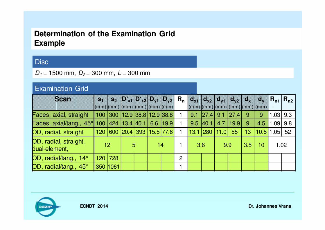
OD, radial, straight, dual-element,
12 5 14 1 3.6 9.9 3.5 10 1.02
OD, radial/tang., 14° 120 728 2
OD, radial/tang., 45° 350 1061 1
D1 = 1500 mm, D2 = 300 mm, L = 300 mm
°
Determination of the Examination GridExample
Disc
Examination Grid

ECNDT 2014 Dr. Johannes Vrana
Scan s1 s2 D‘x1 D‘x2 Dy1 Dy1 Rn dx1 dx2 dy1 dy2 dx dy Rn1 Rn2
(mm) (mm) (mm) (mm) (mm) (mm) (mm) (mm) (mm) (mm) (mm) (mm)
Faces, axial, straight 100 300 12.9 38.8 12.9 38.8 1 9.1 27.4 9.1 27.4 9 9 1.03 9.3
Faces, axial/tang., 45° 100 424 13.4 40.1 6.6 19.9 1 9.5 40.1 4.7 19.9 9 4.5 1.09 9.8
OD, radial, straight 120 600 20.4 393 15.5 77.6 1 13.1 280 11.0 55 13 10.5 1.05 52
OD, radial, straight, dual-element,
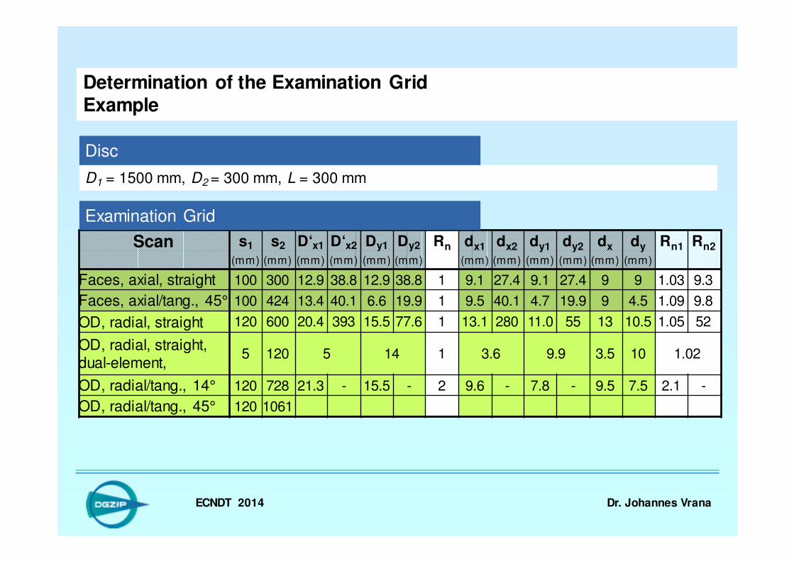
5 120 5 14 1 3.6 9.9 3.5 10 1.02
OD, radial/tang., 14° 120 728 21.3 - 15.5 - 2 9.6 - 7.8 - 9.5 7.5 2.1 -
OD, radial/tang., 45° 350 1061 1
D1 = 1500 mm, D2 = 300 mm, L = 300 mm
°
Determination of the Examination GridExample
Disc
Examination Grid

ECNDT 2014 Dr. Johannes Vrana
Scan s1 s2 D‘x1 D‘x2 Dy1 Dy2 Rn dx1 dx2 dy1 dy2 dx dy Rn1 Rn2
(mm) (mm) (mm) (mm) (mm) (mm) (mm) (mm) (mm) (mm) (mm) (mm)
Faces, axial, straight 100 300 12.9 38.8 12.9 38.8 1 9.1 27.4 9.1 27.4 9 9 1.03 9.3
Faces, axial/tang., 45° 100 424 13.4 40.1 6.6 19.9 1 9.5 40.1 4.7 19.9 9 4.5 1.09 9.8
OD, radial, straight 120 600 20.4 393 15.5 77.6 1 13.1 280 11.0 55 13 10.5 1.05 52
OD, radial, straight, dual-element,
5 120 5 14 1 3.6 9.9 3.5 10 1.02
OD, radial/tang., 14° 120 728 21.3 - 15.5 - 2 9.6 - 7.8 - 9.5 7.5 2.1 -
OD, radial/tang., 45° 350 1061 161 141 24 70 1
D1 = 1500 mm, D2 = 300 mm, L = 300 mm
°
Determination of the Examination GridExample
Disc
Examination Grid

ECNDT 2014 Dr. Johannes Vrana
Scan s1 s2 D‘x1 D‘x2 Dy1 Dy2 Rn dx1 dx2 dy1 dy2 dx dy Rn1 Rn2
(mm) (mm) (mm) (mm) (mm) (mm) (mm) (mm) (mm) (mm) (mm) (mm)
Faces, axial, straight 100 300 12.9 38.8 12.9 38.8 1 9.1 27.4 9.1 27.4 9 9 1.03 9.3
Faces, axial/tang., 45° 100 424 13.4 40.1 6.6 19.9 1 9.5 40.1 4.7 19.9 9 4.5 1.09 9.8
OD, radial, straight 120 600 20.4 393 15.5 77.6 1 13.1 280 11.0 55 13 10.5 1.05 52
OD, radial, straight, dual-element,
5 120 5 14 1 3.6 9.9 3.5 10 1.02
OD, radial/tang., 14° 120 728 21.3 - 15.5 - 2 9.6 - 7.8 - 9.5 7.5 2.1 -
OD, radial/tang., 45° 350 1061 161 141 24 70 1 114 100 16.4 50
D1 = 1500 mm, D2 = 300 mm, L = 300 mm
°
Determination of the Examination GridExample
Disc
Examination Grid

ECNDT 2014 Dr. Johannes Vrana
Scan s1 s2 D‘x1 D‘x2 Dy1 Dy2 Rn dx1 dx2 dy1 dy2 dx dy Rn1 Rn2
(mm) (mm) (mm) (mm) (mm) (mm) (mm) (mm) (mm) (mm) (mm) (mm)
Faces, axial, straight 100 300 12.9 38.8 12.9 38.8 1 9.1 27.4 9.1 27.4 9 9 1.03 9.3
Faces, axial/tang., 45° 100 424 13.4 40.1 6.6 19.9 1 9.5 40.1 4.7 19.9 9 4.5 1.09 9.8
OD, radial, straight 120 600 20.4 393 15.5 77.6 1 13.1 280 11.0 55 13 10.5 1.05 52
OD, radial, straight, dual-element,
5 120 5 14 1 3.6 9.9 3.5 10 1.02
OD, radial/tang., 14° 120 728 21.3 - 15.5 - 2 9.6 - 7.8 - 9.5 7.5 2.1 -
OD, radial/tang., 45° 350 1061 161 141 24 70 1 114 100 16.4 50 100 17 1.09 1.79
D1 = 1500 mm, D2 = 300 mm, L = 300 mm
°
Determination of the Examination GridExample
Disc
Examination Grid
ECNDT 2014 Dr. Johannes Vrana
Scan s1 s2 D‘x1 D‘x2 Dy1 Dy2 Rn dx1 dx2 dy1 dy2 dx dy Rn1 Rn2
(mm) (mm) (mm) (mm) (mm) (mm) (mm) (mm) (mm) (mm) (mm) (mm)
Faces, axial, straight 100 300 12.9 38.8 12.9 38.8 1 9.1 27.4 9.1 27.4 9 9 1.03 9.3
Faces, axial/tang., 45° 100 424 13.4 40.1 6.6 19.9 1 9.5 40.1 4.7 19.9 9 4.5 1.09 9.8
OD, radial, straight 120 600 20.4 393 15.5 77.6 1 13.1 280 11.0 55 13 10.5 1.05 52
OD, radial, straight, dual-element,
5 120 5 14 1 3.6 9.9 3.5 10 1.02
OD, radial/tang., 14° 120 728 21.3 - 15.5 - 2 9.6 - 7.8 - 9.5 7.5 2.1 -
OD, radial/tang., 45° 120 1061
D1 = 1500 mm, D2 = 300 mm, L = 300 mm
°
Determination of the Examination GridExample
Disc
Examination Grid

ECNDT 2014 Dr. Johannes Vrana
Scan s1 s2 D‘x1 D‘x2 Dy1 Dy2 Rn dx1 dx2 dy1 dy2 dx dy Rn1 Rn2
(mm) (mm) (mm) (mm) (mm) (mm) (mm) (mm) (mm) (mm) (mm) (mm)
Faces, axial, straight 100 300 12.9 38.8 12.9 38.8 1 9.1 27.4 9.1 27.4 9 9 1.03 9.3
Faces, axial/tang., 45° 100 424 13.4 40.1 6.6 19.9 1 9.5 40.1 4.7 19.9 9 4.5 1.09 9.8
OD, radial, straight 120 600 20.4 393 15.5 77.6 1 13.1 280 11.0 55 13 10.5 1.05 52
OD, radial, straight, dual-element,
5 120 5 14 1 3.6 9.9 3.5 10 1.02
OD, radial/tang., 14° 120 728 21.3 - 15.5 - 2 9.6 - 7.8 - 9.5 7.5 2.1 -
OD, radial/tang., 45° 120 1061 28 141 10 70 1 19.9 100 7.1 50 20 7 1.0 33
D1 = 1500 mm, D2 = 300 mm, L = 300 mm
°
Determination of the Examination GridExample
Disc
Examination Grid
ECNDT 2014 Dr. Johannes Vrana
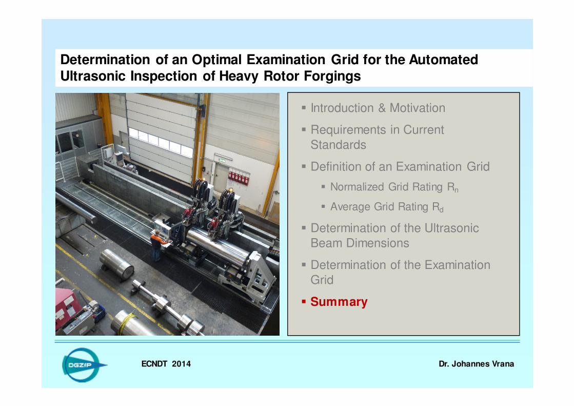
Determination of an Optimal Examination Grid for the Automated Ultrasonic Inspection of Heavy Rotor Forgings
� Introduction & Motivation
� Requirements in Current
Standards
� Definition of an Examination Grid
� Normalized Grid Rating Rn
� Average Grid Rating Rd
� Determination of the Ultrasonic
Beam Dimensions
� Determination of the Examination
Grid
� Summary
ECNDT 2014 Dr. Johannes Vrana
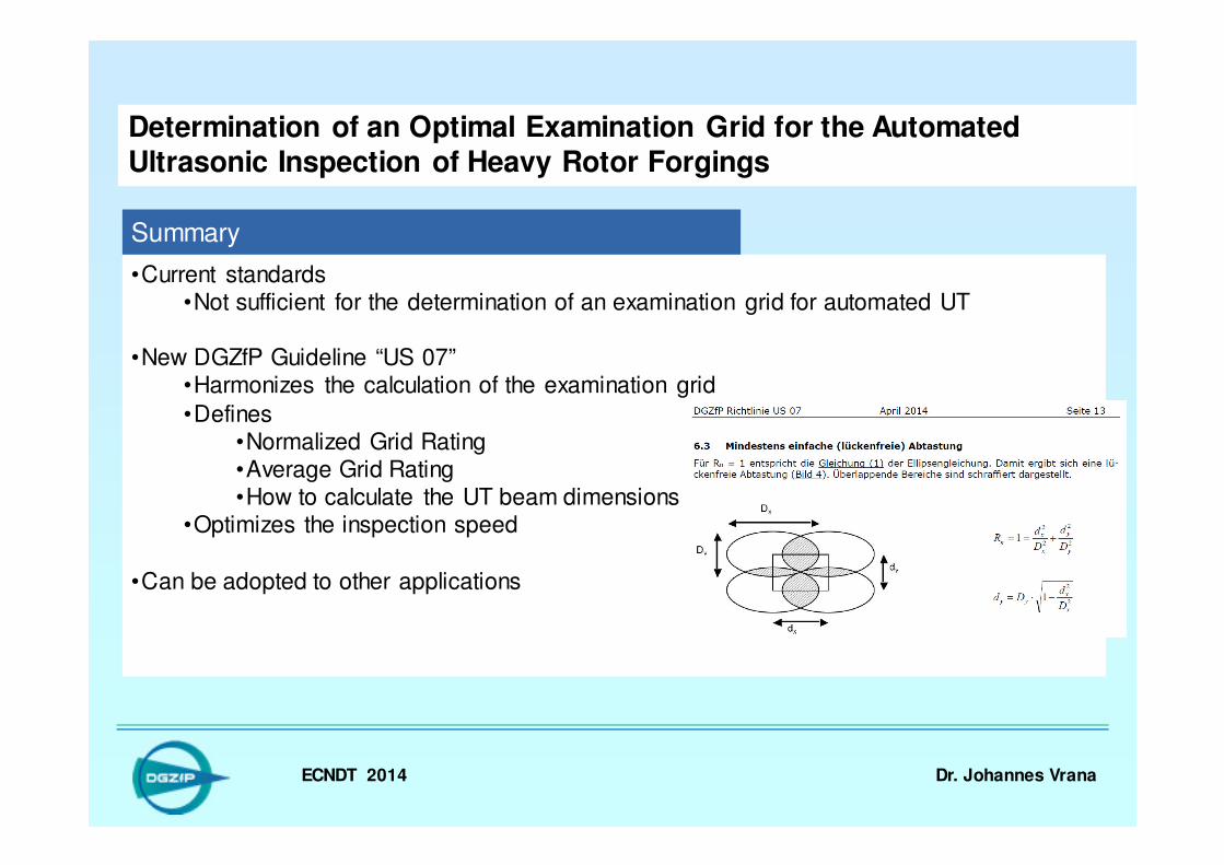
•Current standards•Not sufficient for the determination of an examination grid for automated UT
•New DGZfP Guideline “US 07”•Harmonizes the calculation of the examination grid
•Defines•Normalized Grid Rating•Average Grid Rating•How to calculate the UT beam dimensions
•Optimizes the inspection speed
•Can be adopted to other applications
Determination of an Optimal Examination Grid for the Automated Ultrasonic Inspection of Heavy Rotor Forgings
Summary

ECNDT 2014 Dr. Johannes Vrana
Thanks for paying
attention to all the
formulas
( )
1 1 1
2 2
1 1
1
1
1
2 2' arcsin sin( ) arcsin sin( ) 2
180 2
with ( 2) 2 ( 2) cos( )
2sin( ) for 0
and 2sin for 0
2sin for 0
x
D D DD
r r
r s D s D
D
r D
D
πα ϕ α ϕ ϕ
α
α ϕ α
ϕ α
α ϕ α
= ⋅ + − − ± ⋅ ⋅ ⋅
°
= + − ⋅ ⋅ ⋅
+ >
≥ =
− <
1
1
' in the case /2 cos( )
and ' in the case
wit
/ 2 cos( )
h D s D
D s D
α
α
+
−
> ⋅
≤ ⋅
2
2
2
21
y
y
x
x
nD
d
D
d
R+=
4
π⋅⋅=
y
y
x
xd
d
D
d
DR( ) ( )
( ) ( )αϕ
ϕα
⋅+⋅
⋅⋅⋅⋅=
2cos2cos
2sincos2'
sD x
11
1
' arcsin sin( )2 180
x
DD D
D s
πϕ ϕ
= ⋅ ± ⋅ ⋅ − ⋅ °
1
1
'2
x
x
D DD
D s
⋅=
− ⋅