Embed Size (px)
Citation preview

8/10/2019 Determination of Combustion Parameters Using Engine Crankshaft Speed
http://slidepdf.com/reader/full/determination-of-combustion-parameters-using-engine-crankshaft-speed 1/6
Determination of combustion parameters using enginecrankshaft speed
F. Taglialatela a,n, M. Lavorgna a, E. Mancaruso b, B.M. Vaglieco b
a Automotive Product Group-AED, STMicroelectronics, Vi a Remo De Feo 1, 80022 Arzano (NA), Italyb Istituto Motori-CNR, Via G. Marconi 8, 80125 Napoli, Italy
a r t i c l e i n f o
Article history:
Received 29 November 2011
Received in revised form
3 December 2012
Accepted 24 December 2012Available online 27 February 2013
Keywords:
Combustion control
Cylinder pressure
Crankshaft engine speed
Neural network
Combustion parameters
a b s t r a c t
Electronic engine controls based on real time diagnosis of combustion process can
significantly help in complying with the stricter and stricter regulations on pollutants
emissions and fuel consumption. The most important parameter for the evaluation of
combustion quality in internal combustion engines is the in-cylinder pressure, but its
direct measurement is very expensive and involves an intrusive approach to the cylinder.
Previous researches demonstrated the direct relationship existing between in-cylinder
pressure and engine crankshaft speed and several authors tried to reconstruct the
pressure cycle on the basis of the engine speed signal.
In this paper we propose the use of a Multi-Layer Perceptron neural network to model
the relationship between the engine crankshaft speed and some parameters derived from
the in-cylinder pressure cycle. This allows to have a non-intrusive estimation of cylinder
pressure and a real time evaluation of combustion quality. The structure of the model
and the training procedure is outlined in the paper. A possible combustion controller
using the information extracted from the crankshaft speed information is also proposed.
The application of the neural network model is demonstrated on a single-cylinder spark
ignition engine tested in a wide range of speeds and loads. Results confirm that a good
estimation of some combustion pressure parameters can be obtained by means of a
suitable processing of crankshaft speed signal.
& 2013 Elsevier Ltd. All rights reserved.
1. Introduction
Development of advanced engine control systems for the modern 4-stroke internal combustion engine is being driven by
demand for higher fuel economy and increasingly stringent exhaust emissions standards and noise vibrations and hardness
(NVH). Moreover, emissions compliance must be maintained for increasing service duration while on-board-diagnostics
(OBD) requirements are satisfied. In-cylinder-pressure-based feedback control is an ideal method to optimize engine
operation [1, 2] over engine and vehicle life while fulfilling diagnostics requirements. In spark ignition (SI) engines, oxygen
sensors mounted in the exhaust pipe provide a possibility for closed loop air-fuel ratio control and piezo-electric knock
sensors mounted on the engine block, for closed loop knock control, but the need for supervising the combustion process
itself increases constantly. In order to comply with the severe future normative on pollutants emissions and fuel
Contents lists available at SciVerse ScienceDirect
journal homepage: www.elsevier.com/locate/ymssp
Mechanical Systems and Signal Processing
0888-3270/$- see front matter & 2013 Elsevier Ltd. All rights reserved.http://dx.doi.org/10.1016/j.ymssp.2012.12.009
Abbreviations: CAD, Crank Angle Degree; ECU, Electronic Control Unit; PP, in-cylinder Pressure Peak; LPP, angular Location of Pressure Peak;
MLP, Multi-Layer Perceptron; NVH, Noise Vibrations and Hardness; OBD, On-Board-Diagnostics; PFI, Port Fuel Injection; RMSE, Root Mean Square Error;
RBF, Radial Basis Function; SI, Spark Ignitionn Corresponding author. Tel.: þ39 0817177204; fax: þ39 0812381114.
E-mail address: [email protected] (F. Taglialatela).
Mechanical Systems and Signal Processing 38 (2013) 628–633

8/10/2019 Determination of Combustion Parameters Using Engine Crankshaft Speed
http://slidepdf.com/reader/full/determination-of-combustion-parameters-using-engine-crankshaft-speed 2/6
consumption, real-time diagnostics for combustion process monitoring in internal combustion engines are required.
Information on the combustion efficiency may provide a strong tool regarding engine operation and may be profitably
used for closed-loop electronic engine controls. One of the most important parameters used for the evaluation of the
combustion quality is the in-cylinder pressure. However, this kind of measure requires an intrusive approach to the cylinder
and a special mounting process. Moreover, the combustion pressure transducers used for this kind of applications still have
an high cost for mass production automotive engines and still remains some problems of robustness and performances. Due
to the disadvantage of direct pressure measurement, several non-intrusive techniques have been proposed to reconstruct the
cylinder pressure and obtain information about the combustion quality [1–3]. The non-intrusive diagnostics offer severaladvantages: the sensors are generally placed externally the engine and no engine structural modifications are required.
Moreover, the non-intrusive sensors are not requested to resist very high pressures and temperatures; so these sensors can
be relatively cheap.
The strong connection between the characteristics of the combustion process and the so called ‘‘vibration signature’’ of
the engine, induced some authors to try a reconstruction of the cylinder pressure by using the vibration signal coming
from an accelerometer placed on the engine block [4–6]. The signal processing tools used for that purpose were: de-
convolution methods, spectrum analysis, cyclo-stationarity properties and methods using neural network models [7,8].
An approach based on the analysis of the instantaneous crankshaft speed for cylinder pressure reconstruction is
considered to be more successful and is, therefore, widely used both for its simplicity and its low cost [9–15]. In [9,10], the
measured crankshaft angular speed was fed into a simple engine model to determine the waveform of indicated torque.
This indicated torque was then used to calculate the corresponding cylinder pressure. Other authors changed the system
independent variable from time to crank angle; with this change, an engine model can be represented by a time-varying
linear first-order differential equation instead of a non-linear differential equation. Using this linear engine model and astochastic pressure model, the cylinder pressure was reconstructed through a Kalman-filter-based de-convolution
algorithm [11]. However, all these model based approaches have the disadvantages of being inextricably tied to the
simplifying assumptions needed to construct the engine model. Model errors and inadequate assumptions can lead to
considerable deviations. In [13], a neural network approach is proposed for the reconstruction of cylinder pressure curve.
The input signals used for this reconstruction were the engine crankshaft angular speed and the in-cylinder motored
pressure. This means that, in order to real-time predict the combustion pressure cycle, an in-cylinder pressure transducer
is still needed for the acquisition of motored pressure signal. Also in [14], a radial basis function (RBF) neural network
model for the estimation of the in-cylinder pressure is presented. The model uses the engine angular speed as input value.
However, both [13,14] use neural networks for the estimation of the whole in-cylinder pressure curve. This requires a
strong computational effort to electronic control unit (ECU) microcontrollers, but it could not be necessary for real-time
engine controls. As a matter of fact, the majority of engine control architectures that use feedbacks from the combustion
pressure only employ some parameters extracted from the pressure cycle, and not the whole cycle.
The present study is concerned with the prediction, for control purposes, of some parameters of the cylinder pressurecycle. In particular, the work aims to estimate the in-cylinder pressure peak value and its angular location by using a
neural network approach. The trained network can be viewed as a non-parametric model of the engine process and it has
as inputs the engine angular crankshaft speed and the crankshaft speed derivative. The parameters of the pressure cycle
obtained by means of the proposed approach can be used for real time engine control. So, a control system which uses the
pressure peak angular location value for real time modification of ignition angle is also proposed in the paper. A possible
control system for gasoline engines could use the pressure peak angular location, obtained from the neural network model,
as a feedback value for real time determination of ignition angle.
The engine used both for the training of the neural network model and for its validation was a research single-cylinder
gasoline engine.
2. Materials and methods
In order to train and validate the neural network model, a research single cylinder engine was used. In particular, theengine was a port fuel injection (PFI) gasoline engine, and it was equipped with the cylinder head of the new generation of
Table 1
Main features of the single-cylinder PFI test engine.
Engine type Port fuel injection
Engine design 1 Cylinder, 4 valves
Bore/stroke/displacement 79 mm/81.3 mm/399 cm3
Max Torque 20 N m/2500 rpm
Max power 10 kW/2500 rpm
Combustion chamber Pent-roof
Compression ratio 10:1
Max speed 2500 rpm
F. Taglialatela et al. / Mechanical Systems and Signal Processing 38 (2013) 628–633 629

8/10/2019 Determination of Combustion Parameters Using Engine Crankshaft Speed
http://slidepdf.com/reader/full/determination-of-combustion-parameters-using-engine-crankshaft-speed 3/6
SI turbocharged engines. Details about the engine are reported in Table 1. The head had four valves and the combustion
chamber was characterized by pent-roof geometry and a centrally located spark plug (see Fig. 1).
The in-cylinder pressure was measured by means of a pressure transducer (AVL-GM12D). To avoid either cavity
resonance and/or low sensitivity to the pressure oscillations of abnormal combustion, in all investigations piezo-electric
transducer was flush installed. This entered vertically from the top of the cylinder head and was positioned in the regionbetween the intake and exhaust valves. A cylinder pressure charge amplifier equipped with 200 kHz analog filter was used
to convert the transducer charge into signals with a 710 V.
A high precision Crank Angle Optical Encoder was used for instantaneous crankshaft speed measurement. Data
acquisition was fixed at 0.11 crank angle.
3. Neural network model
A neural network approach was used to model the non-linear correlation between the engine crankshaft speed and some
parameters extracted from the combustion pressure curve, such as the pressure peak value and its angular location. So, the
neural network model had as input the engine crankshaft speed and its derivative, i.e. the crankshaft acceleration; whereas
the outputs of the model were represented by the in-cylinder pressure peak (PP) and its angular location (LPP) (see Fig. 2).
In order to train and validate the neural network model, measurements were carried out over the engine speed range1000–2000 rpm, with steps of 200 rpm. The equivalence ratio was fixed at l¼1 as measured by a lambda sensor installed at
the engine exhaust. The injection pressure was fixed at 3.5 bar over the boost pressure. Only full load (wide open throttle)
and boosting conditions were employed for all measurements on the engine reported in this paper. The reason for this choice
relies on some limitations of the single-cylinder test engine, which was developed for research purposes only. So, for each
engine speed, absolute intake pressures ranging from 1000 mbar to 1600 mbar, with steps of 200 mbar, were selected.
For each engine operating condition, 400 consecutive pressure cycles and the correspondent crankshaft speeds were
acquired.
The overall dataset was then divided into two groups. One group was used as training dataset that is to train the neural
network model and to set the internal model parameters. The other group was used as testing dataset that is to validate
the trained network.
As neural network, we used a Multi-Layer Perceptron (i.e. MLP) neural network. However, also other neural networks
(such as radial basis function networks or recurrent neural networks) could be chosen to the same aim. The MLP had only a
hidden layer with 30 neurons and the arctan as activation function. As algorithm for the training phase, we selected thetrainbr algorithm contained in the Matlab neural network library. The trainbr algorithm is a network training function that
Fig. 1. Combustion chamber of the test engine.
Fig. 2. Inputs and outputs of neural network model.
F. Taglialatela et al. / Mechanical Systems and Signal Processing 38 (2013) 628–633630
8/10/2019 Determination of Combustion Parameters Using Engine Crankshaft Speed
http://slidepdf.com/reader/full/determination-of-combustion-parameters-using-engine-crankshaft-speed 4/6
minimizes a combination of squared errors and weights, and then determines the correct combination so as to produce a
network that generalizes well. This process is called Bayesian regularization. Use of this process guaranteed a satisfactory
generalization capability of the neural network model and, at the same time, allowed to avoid over-fitting issues. The
tuning of the internal parameters (e.g. the value of the regularization parameter, neuron biases, etc.) of the neural network
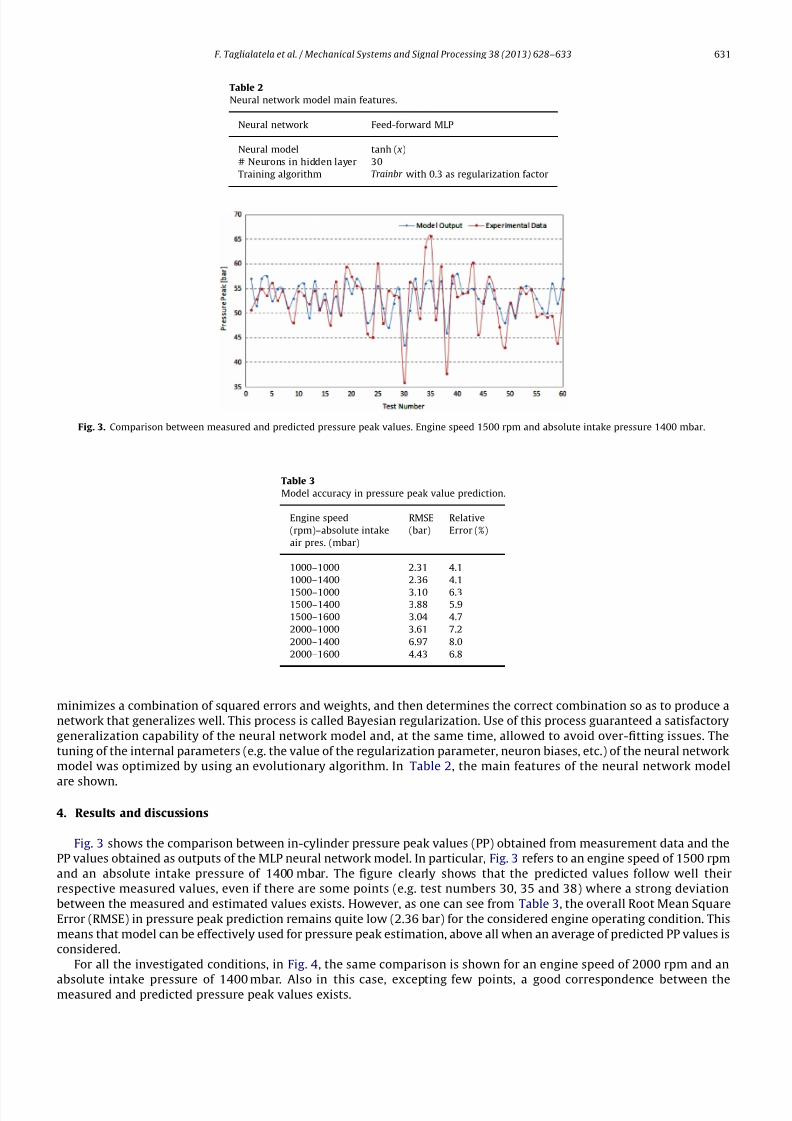
model was optimized by using an evolutionary algorithm. In Table 2, the main features of the neural network model
are shown.
4. Results and discussions
Fig. 3 shows the comparison between in-cylinder pressure peak values (PP) obtained from measurement data and the
PP values obtained as outputs of the MLP neural network model. In particular, Fig. 3 refers to an engine speed of 1500 rpm
and an absolute intake pressure of 1400 mbar. The figure clearly shows that the predicted values follow well their
respective measured values, even if there are some points (e.g. test numbers 30, 35 and 38) where a strong deviation
between the measured and estimated values exists. However, as one can see from Table 3, the overall Root Mean Square
Error (RMSE) in pressure peak prediction remains quite low (2.36 bar) for the considered engine operating condition. This
means that model can be effectively used for pressure peak estimation, above all when an average of predicted PP values is
considered.
For all the investigated conditions, in Fig. 4, the same comparison is shown for an engine speed of 2000 rpm and an
absolute intake pressure of 1400 mbar. Also in this case, excepting few points, a good correspondence between themeasured and predicted pressure peak values exists.
Table 2
Neural network model main features.
Neural network Feed-forward MLP
Neural model tanh ( x)
# Neurons in hidden layer 30
Training algorithm Trainbr with 0.3 as regularization factor
Fig. 3. Comparison between measured and predicted pressure peak values. Engine speed 1500 rpm and absolute intake pressure 1400 mbar.
Table 3
Model accuracy in pressure peak value prediction.
Engine speed
(rpm)–absolute intake
air pres. (mbar)
RMSE
(bar)
Relative
Error (%)
1000–1000 2.31 4.1
1000–1400 2.36 4.1
1500–1000 3.10 6.31500–1400 3.88 5.9
1500–1600 3.04 4.7
2000–1000 3.61 7.2
2000–1400 6.97 8.0
2000–1600 4.43 6.8
F. Taglialatela et al. / Mechanical Systems and Signal Processing 38 (2013) 628–633 631

8/10/2019 Determination of Combustion Parameters Using Engine Crankshaft Speed
http://slidepdf.com/reader/full/determination-of-combustion-parameters-using-engine-crankshaft-speed 5/6
In both the above considered engine operating conditions (more clearly at 2000 rpm to 1400 mbar), some engine cycles
with an instantaneous strong reduction of pressure peak values can be observed. This pressure peak reduction is generally
due to inefficient combustions or even to misfiring combustions. As one can see from the reported graphs, the trained
neural network model is able to predict these combustion anomalies following the instantaneous pressure peak reductions
observed in the measured data. So, the proposed model can be used as a non-intrusive diagnostic tool for real time
evaluation of engine combustion quality and then it can be employed in advanced closed-loop control systems.
In Fig. 5, the results about the prediction of angular location of pressure peak (LPP) are reported. In particular, the
graphs show the comparison between the predicted LPP values and LPP values obtained from the measured data. Fig. 5
refers to engine speed of 1500 rpm and an absolute intake pressure of 1600 rpm, whereas Fig. 5 refers to an engine speed
of 2000 rpm and an absolute intake pressure of 1600 mbar.
Both the figures show that the model has a good capability of predicting the angular location of pressure peak. Also in
this case there are some points where LPP estimated values greatly differ from those obtained from experimental data,
even if the global error in LPP prediction is very low (below 3.5 Crank Angle Degrees).
Table 3 shows the RMSE of the model in pressure peak prediction. For all the operating conditions of the testing dataset,
the RMSE is lower than 7 bar. It also comes out that RMSE increases as the engine speed increases. Third column of Table 3
shows the Relative Error: it is less than 8% for all the engine operating conditions. However, for engine speeds lower than
2000 rpm, the Relative Error is strongly reduced and it becomes 4.1% at 1000 rpm. Note that Relative Error was calculated
scaling the RMSE by the maximum of the peak pressure of the test dataset.
Table 4 shows the results of the prediction of pressure peak location. The maximum RMSE is 5.20 Crank Angle Degrees
(CAD) and, also in this case, the RMSE increases as the engine speed increases. Except the third and sixth engine operating
conditions, the Relative Error maintains lower than 9.1%.
5. Closed loop control algorithm
The previous sections showed that a suitable processing of engine crankshaft speed allows the estimation of some
important combustion parameters, such as in-cylinder pressure peak (PP ) and its angular location (LPP ). Among these, the
LPP , as it is strictly connected to the ignition angle, represents a very promising control variable for closed loop gasoline
engine ignition control. A possible engine controller could estimate the LPP from the crankshaft speed information and
could use it as a feedback variable in a spark timing controller. This allows to maintain the LPP close to its reference value
modifying, if requested, the spark advance value stored in the control maps. For each engine speed and engine load, the LPP set-point can be defined as the optimal value to obtain the desired engine behaviour. In high load ranges, for example, late
Fig. 4. Comparison between measured and predicted angular locations of the maximum pressure. Engine speed 1500 rpm and absolute intake pressure
1600 mbar
Fig. 5. Ignition timing closed loop control using crankshaft speed signal as feedback variable.
F. Taglialatela et al. / Mechanical Systems and Signal Processing 38 (2013) 628–633632

8/10/2019 Determination of Combustion Parameters Using Engine Crankshaft Speed
http://slidepdf.com/reader/full/determination-of-combustion-parameters-using-engine-crankshaft-speed 6/6
pressure peak locations could be requested to hold down the NOx emissions. A block scheme of the conceived engine
closed-loop control is shown in Fig. 5. The architecture includes a proportional-integral controller for LPP control.
6. Conclusions
A neural network model for the prediction of some parameters from the cylinder pressure curve has been proposed. Theneural network has as inputs the engine angular crankshaft speed and the crankshaft speed derivative. The outputs of the
model are represented by the in-cylinder pressure peak (PP ) and its angular location (LPP ).
Both for PP and LPP , a good correspondence between the measured and predicted values exists for all the tested
conditions even if some deviations can occur on a cyclic basis. The model also seems to be capable of predicting
instantaneous variations of PP and LPP due to combustion anomalies, such as misfire and partial burning. Thus, the
proposed model can represent an important tool for advanced engine control systems. A closed loop control system that
uses the LPP value for real time modification of spark advance angle was also proposed in the paper.
References
[1] C. Mobley, Non-Intrusive In-Cylinder Pressure Measurement of Internal Combustion Engines, SAE Paper No. 1999-01-0544, 1999.[2] J. Patterson, D. Panousakis, A. Gasiz, R. Chen, Analysis of SI Combustion Diagnostics Methods Using Ion-Current Sensing Techniques, SAE Paper No.
2006-01-1345, 2006.[3] M. Wlodarczyk, High Accuracy Glow Plug-Integrated Cylinder Pressure Sensor for Closed Loop Engine Control, SAE Paper No. 2006-01-0184, 2006.[4] M. Wagner, S. Carstens-Behrens, J.F. Bohme, In-cylinder pressure estimation using structural vibration measurements of spark ignition engines, in:
Proceedings of the IEEE Signal Processing Workshop on Higher-Order Statistics, 14–16 giu 1999, Caesarea, Israel, 1999, pp. 174–177.[5] R. Villarino, J.F. Bohme, Peak Pressure Position Estimation from Structure-Borne Sound, SAE Paper No. 2005-01-0040, 2005.[6] C.J. Polonowski, V. Mathur, J. Naber, J. Blough, Accelerometer Based Sensing of Combustion in a High Speed HPCR Diesel Engine, SAE Paper No. 2007-
01-0972, 2007.[7] J. Antoni, J. Daniere, F. Guillet, Effective vibration analysis of IC engines using cyclostationarity. Part 1. A methodology for condition monitoring,
J. Sound Vib. 257 (2002) 815–837.[8] R. Johnsson, Cylinder pressure reconstruction based on complex radial basis function networks from vibration and speed signals, Mech. Syst. Signal
Process. 20 (8) (2006) 1923–1940.[9] S.J. Citron, J.E. O’Higgins, L.Y. Chen, Cylinder by Cylinder Engine Pressure and Pressure Torque Waveform Determination Utilizing Speed Fluctuations,
SAE Paper No. 890486, 1989.[10] G. Rizzoni, Diagnosis-of Individual Cylinder Misfires by Signature Analysis of Crankshaft Speed Fluctuations, SAE Paper No. 890884, .[11] F.T. Connolly, A.E. Yagle, Modeling and Identification of the Combustion Pressure Process in Internal Combustion Engines Using Engine Speed
Fluctuations, vol. 44, American Society of Mechanical Engineers, Dynamic Systems and Control Division, Anaheim, CA, 1992, pp. 191–206.[12] D. Moro, N. Cavina, F. Ponti, In-cylinder pressure reconstruction based on instantaneous engine speed signal, J. Eng. Gas Turbines Power 124 (2002)
220–225.[13] S. Saraswati, S. Chand, Reconstruction of cylinder pressure for SI engine using recurrent neural network, Neural Comput. Appl. 19 (2010) 935–944.[14] F. Gu, P.J. Jacob, A.D. Ball, A RBF neural network model for cylinder pressure reconstruction in internal combustion engines, IEE Colloquium on
Modelling and Signal Processing for Fault Diagnosis, Digest No: 1996/260, 1996.[15] F. Liu, G.A.J. Amaratunga, N. Collings, A. Soliman, An Experimental Study on Engine Dynamics Model Based In-Cylinder Pressure Estimation, SAE
Paper No. 2012-01-0896, 2012.
Table 4
Model accuracy in pressure peak location prediction.
Engine speed (rpm)–
absolute intake air pres.
(mbar)
RMSE
[CAD]
Relative
Error (%)
1000–1000 1.38 5.2
1000–1400 1.66 4.9
1500–1000 2.44 9.01500–1400 347 8.9
1500–1600 2.03 4.8
2000–1000 4.05 9.1
2000–1400 5.20 8.8
2000–1600 3.36 5.9
F. Taglialatela et al. / Mechanical Systems and Signal Processing 38 (2013) 628–633 633