Embed Size (px)
Citation preview

European Process Industries STEP Technical Liaison Executive
Developing High Quality Data Models Abstract: This document describes how to develop data models so they are stable, flexible to changing business practices, and extensible to changing business needs. Version: 2.0 Issue: 2.1
Author: Matthew West Editor: Julian Fowler
Further copies are available from:
Matthew West Shell International Limited ISCL/4, Shell Centre, London, SE1 7NA, UK
Fax: +44 171 934 6786
E-mail: [email protected]

page ii
File name: PRINC03.DOC
Copyright Notice
The copyright of the contents of this document is assigned to EPISTLE (the European Process Industries STEP Technical Liaison Executive) and its successors. However, the contents may be freely distributed or copied, in full or in part, provided due acknowledgement is made.
Version Date Comments
Issue 1.0 - Draft 8-Dec-95 First cut taken from "Developing High Quality Data Models" - for comment
Issue 2.0 18-Mar-96 Restructured to bring in material from Managing Data Quality, Managing Shared Data, and Reviewing and Improving Data Models.
Issue 3.0 27-Aug-96 All diagrams changed from Oracle*CASE notation to EXPRESS-G, captions and cross-references corrected.
Editor’s note
It is proposed that this next release will also be available as a fully searchable HTML document for placement on the EPISTLE web site maintained by the University of Newcastle.
Developing High Quality Data Models
Acknowledgement
This document is based on work first undertaken for Shell International. Permission to use and extend this work is gratefully acknowledged. I would also like to acknowledge the contribution made by members of EPISTLE to the development of this work.
Page iii
Contents
1. Executive Summary 1
2. Introduction 2
2.1 Purpose 2 2.2 Target Audience 2 2.3 Prerequisites 2 2.4 Structure 2 2.5 Relationship to Previous Work 2
3. A Business Perspective of Information 4
3.1 The Role of Information 4 3.2 Key Requirements for Information 4 3.3 The Promise of Computer Based Information 6 3.4 Key Requirements for Information Systems 6 3.5 The Reality of Computer Based Information 6 3.6 The Role of Data Models 7
4. The Need for Standards 9
4.1 Background 9 4.2 The ANSI/SPARC Architecture 9 4.3 Requirements for Data Models 10 4.4 Data Modelling Today 11 4.5 Some Issues for Data Models 11 4.6 Required Standards 13 4.7 Principles for Conceptual Data Models 14
5. Principles for Attributes 15
5.1 An Example - Sales Product 15 5.2 An Example - Personnel and Security 17 5.3 Principle 1 19 5.4 Identification 20 5.5 Internal Identification 20 5.6 The Trap - Inappropriate Choice of Unique Identifier. 20 5.7 An Example - Ship 20
Developing High Quality Data Models 2-Sep-03
Page iv
5.8 Another Example - Packed Product 21 5.9 Principle 2 22 5.10 External Identification 23 5.11 Record Identifiers 23 5.12 Expected Attributes 23
6. Principles for Relationships 24
6.1 Relationships and Associations 24 6.2 A Bad Example - Batch and Product Type 24 6.3 A Second Example - Packed Products 25 6.4 The Trap 25 6.5 An Example - Ship 26 6.6 A Good Example - Transfer and Storage 27 6.7 Principle 3 28 6.8 Principle 4 28
7. Principles for Entity Types 29
7.1 An Example - Combined Entity Types 29 7.2 An Example - Stock 30 7.3 Naming Entity Types 31 7.4 The Trap - Fixed Hierarchies. 32 7.5 An Example - Stock Classification 32 7.6 Principle 5 35 7.7 Context and Scope 36 7.8 Principle 6 38 7.9 Impact of Using the Principles 38
8. Ah But ... 41
8.1 But What About Performance? 41 8.20.1. But How Do I Implement the Rules? 42 8.3 But I Want a Data Model I Can Show My Users 42 8.4 But Won't I Have To Redevelop All My Applications? 43 8.5 But what about Object Orientation? 44 8.6 But Why Stop Here? 45
8.6.1 Really Generic! 45 8.6.2 Flexible and Stable 45
8.7 But Won't it Take Longer to Develop Data Models? 45
2-Sep-03 Developing High Quality Data Models

Page v
9. Techniques for Creating Data Models 46
9.1 Source Material 46 9.1.1 Activity models, Interviews, and Forms 46 9.1.2 Existing Systems 46
9.2 Workshops 46 9.2.1 Mapping to the Generic Entity Framework 46 9.2.2 Selecting and Using Templates 47 9.2.3 Use of Populations to Illustrate Usage 47 9.2.4 Using Examples To Check The Model 47 9.2.5 Resolving Conflicts 48
9.3 Documenting Data Models for Others 48 9.3.1 Subject Areas - Size and Layout 48 9.3.2 Subject Area Descriptions 49 9.3.3 Examples 49 9.3.4 Entity Type Definitions 49 9.3.5 Entity Type to Subject Area Cross Reference 49 9.3.6 Estimating Guidelines for Documentation 50
10. EXPRESS-G Notation 51
Developing High Quality Data Models 2-Sep-03

Page vi
this page intentionally blank
2-Sep-03 Developing High Quality Data Models
Page 1
1. Executive Summary To manage information, information systems must:
• know what information they have, and what it is about, • extract portions of the information base suitable for a particular purpose, • exchange data between organisations and systems, • integrate information from different sources, resolving what is about things they already
have information about, and what is about new things, • share the same data between applications and users with different views, and • manage the data, including history, for life.
This means that we need standards so that data has the same meaning in different organisations and systems. The current lack of standards means that systems and interfaces often cost more than they should, to build, operate, and maintain. They may also constrain the business rather than support it. A major cause is that the quality of the data models implemented in systems and interfaces is poor.
• Business rules, specific to how things are done in a particular place, are often fixed in the structure of a data model. This means that small changes in the way business is conducted lead to large changes in computer systems and interfaces.
• Entity types are often not identified, or incorrectly identified. This can lead to replication of data, data structure, and functionality, together with the attendant costs of that duplication in development and maintenance.
• Data models for different systems are arbitrarily different. The result of this is that complex interfaces are required between systems that share data. These interfaces can account for between 25-70% of the cost of current systems.
• Data cannot be shared electronically with customers and suppliers, because the structure and meaning of data has not been standardised. For example, engineering design data and drawings for process plant are still sometimes exchanged on paper.
The membership of EPISTLE have been involved in the development of a significant number of data models, and have had the opportunity to review a large number of other data models. The need has been recognised to establish good practice in the development of data models.
This document presents the following principles whose application will help in developing high quality data models.
1. Candidate attributes should be treated as representing relationships to other entity types. 2. Entities should have a local identifier within a database or exchange file. These should be
artificial and managed to be unique. Relationships should not be used as part of the local identifier.
3. Activities, associations and event-effects should be represented by entity types (not relationships or attributes).
4. Relationships (in the entity/relationship sense) should only be used to express the involvement of entity types with activities or associations.
5. Entity types should represent, and be named after, the underlying nature of an object, not the role it plays in a particular context.
6. Entity types should be part of a subtype/ super type hierarchy of generic entity types in order to define a universal context for the model.
Developing High Quality Data Models 2-Sep-03

Page 2
2. Introduction
2.1 Purpose
A data model defines the structure and meaning of data. This document is primarily concerned with data models that enable the reuse of data by different applications, either by integrating and sharing data within a single database, or exchanging data by some other means such as a file transfer.
This document aims to provide a practical guide to developing high quality data models. After reading and understanding this guide, those who create data models should know the principles to apply in order to develop data models that will:
√ meet the data requirement, √ be clear and unambiguous to all (not just the authors), √ be stable in the face of changing data requirements, √ be flexible in the face of changing business practices, √ be reusable by others, √ be consistent with other models covering the same scope (if they were developed following
these principles), and √ be able to integrate data from different data models.
In addition, they should be able to develop data models faster.
2.2 Target Audience
This document is addressed to those involved in the preparation and review of data models.
2.3 Prerequisites
A basic knowledge of entity relationship modelling is an advantage when reading this document. A recommended text is "Oracle CASE*Method - Entity Relationship Modelling", by Richard Barker, Addison-Wesley ISBN 0-201-41696-4.
2.4 Structure
This document:
• presents the background that gives rise to the need to establish good practice in data model development,
• identifies principles which contribute to the development of high quality data models, • answers common questions that arise, and • presents some techniques that can help preparing and documenting data models.
2.5 Relationship to Previous Work
This document draws on and develops work originally undertaken for and published by Shell International - Information Services in a number of booklets including:
1. "Managing Data Quality", IC92-124, Matthew West, November 1993.
2. "Managing Shared Data", IC91-078, Matthew West, Malcolm McEwan February 1992.
2-Sep-03 Developing High Quality Data Models
Page 3
3. "Reviewing and Improving Data Models", IC91-077 T3, Bruce Ottmann, Matthew West, Sandy Fyfe, December 1992.
4. "Developing High Quality Data Models Volume 1: Principles and Techniques", IC94-033, Matthew West, March 1994.
5. "Developing High Quality Data Models Volume 2: The Generic Entity Framework, Version 1.0", IC94-034, Matthew West, March 1994.
6. "Developing High Quality Data Models Volume 3: Data Model Templates", IC94-035, Matthew West, March 1994.
7. "The Database Design Process", IC91-077 T1, Fre van der Werff, December 1991.
8. "Flexibility in Database Design", IC91-077 T2, Fre van der Werff, March 1993.
9. "Entity Type and Relationship Naming Standards", IC94-036, Matthew West, April 1994.
10. "Logical Attribute Naming Standard - Volume 1: The Standard", IC91-077 S2, Matthew West, June 1993.
11. "Logical Attribute Naming Standard - Volume 2: Word Lists", IC91-077 S2, Matthew West, June 1993.
This document brings much of this work together, and aims to present it in a way that makes this difficult subject as accessible as possible. It also develops the ideas in these original documents based on the experience gained since they were originally published, especially in the EPISTLE forum.
Developing High Quality Data Models 2-Sep-03
Page 4
3. A Business Perspective of Information
3.1 The Role of Information
Decisions
Information
Reduced Risk
Identify Business OpportunitiesResponsive to change
YourBusiness
drive
Supports
Increased effectivenessReduced Cost
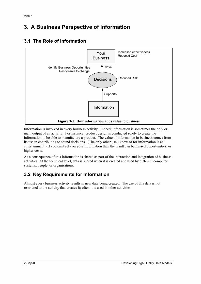
Figure 3-1: How information adds value to business
Information is involved in every business activity. Indeed, information is sometimes the only or main output of an activity. For instance, product design is conducted solely to create the information to be able to manufacture a product. The value of information in business comes from its use in contributing to sound decisions. (The only other use I know of for information is as entertainment.) If you can't rely on your information then the result can be missed opportunities, or higher costs.
As a consequence of this information is shared as part of the interaction and integration of business activities. At the technical level, data is shared when it is created and used by different computer systems, people, or organisations.
3.2 Key Requirements for Information
Almost every business activity results in new data being created. The use of this data is not restricted to the activity that creates it; often it is used in other activities.
2-Sep-03 Developing High Quality Data Models
Page 5
Data QualityRelevance
Clarity Consistency
Accuracy
Completeness
Timeliness
Accessibility
Cost
Data Definition
Data Values
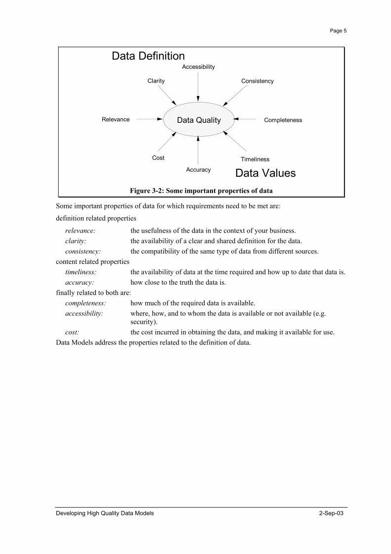
Figure 3-2: Some important properties of data
Some important properties of data for which requirements need to be met are:
definition related properties
relevance: the usefulness of the data in the context of your business. clarity: the availability of a clear and shared definition for the data. consistency: the compatibility of the same type of data from different sources.
content related properties timeliness: the availability of data at the time required and how up to date that data is. accuracy: how close to the truth the data is.
finally related to both are: completeness: how much of the required data is available. accessibility: where, how, and to whom the data is available or not available (e.g.
security). cost: the cost incurred in obtaining the data, and making it available for use.
Data Models address the properties related to the definition of data.
Developing High Quality Data Models 2-Sep-03
Page 6
3.3 The Promise of Computer Based Information
Image Symbolic Syntactic Semantic
Bit MapInk on Paper
CharactersVector Graphics
HypertextLinked Files
"Intelligent" CADExample
Touch Up Spell CheckScale Drawing
Human Navigable Links
Computer Navigable Links
Computer Support
In the Content In the StructureMeaning
FAXTIFF
ASCIICGMDXF
OLECDA
SGML
STEPPOSC
Standards
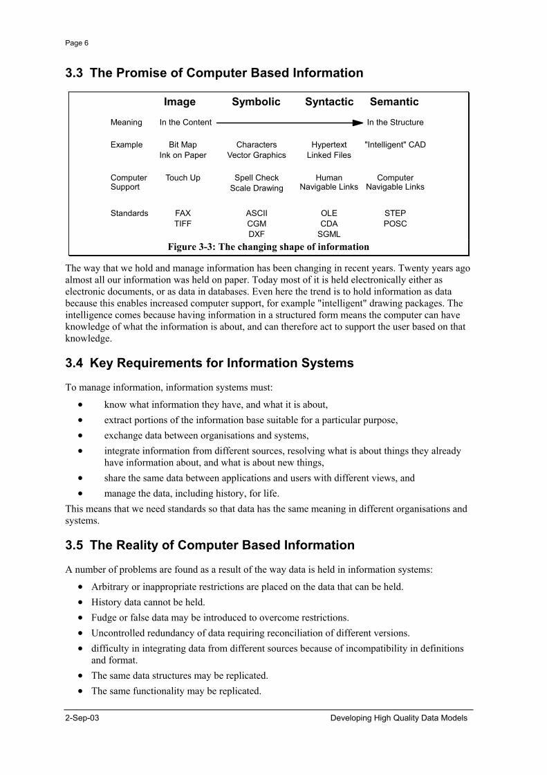
Figure 3-3: The changing shape of information
The way that we hold and manage information has been changing in recent years. Twenty years ago almost all our information was held on paper. Today most of it is held electronically either as electronic documents, or as data in databases. Even here the trend is to hold information as data because this enables increased computer support, for example "intelligent" drawing packages. The intelligence comes because having information in a structured form means the computer can have knowledge of what the information is about, and can therefore act to support the user based on that knowledge.
3.4 Key Requirements for Information Systems
To manage information, information systems must:
• know what information they have, and what it is about, • extract portions of the information base suitable for a particular purpose, • exchange data between organisations and systems, • integrate information from different sources, resolving what is about things they already
have information about, and what is about new things, • share the same data between applications and users with different views, and • manage the data, including history, for life.
This means that we need standards so that data has the same meaning in different organisations and systems.
3.5 The Reality of Computer Based Information
A number of problems are found as a result of the way data is held in information systems:
• Arbitrary or inappropriate restrictions are placed on the data that can be held. • History data cannot be held. • Fudge or false data may be introduced to overcome restrictions. • Uncontrolled redundancy of data requiring reconciliation of different versions. • difficulty in integrating data from different sources because of incompatibility in definitions
and format. • The same data structures may be replicated. • The same functionality may be replicated.
2-Sep-03 Developing High Quality Data Models
Page 7
All of these problems either restrict the way a company does business, or add to the cost of doing business. Here are some financial and time penalties incurred when these problems are encountered:
• Translating data is expensive. The cost of interfaces to translate the meaning of data can account for 25-70% of the total cost of a system development project.
• The need to translate data means that users of different systems can often only share data sequentially, and not concurrently. This can extend the time required for critical business processes.
• There is a slower response to the need for change in systems. Interfaces cost time as well as money.
• Quality suffers. Duplication of data is inefficient and invites errors, which may lead to inferior business decisions.
• Staff time is wasted trying to locate and reconcile data.
3.6 The Role of Data Models
Systems Integration
Compatible Data
Minimum Redundancy of
Data
Business Opportunity
Data Model
SystemsData
Your Business
Supports
Supports
Responsive to Change
Reduced Costs
Reduced Risk
Increased Effectiveness
Simple Interfaces
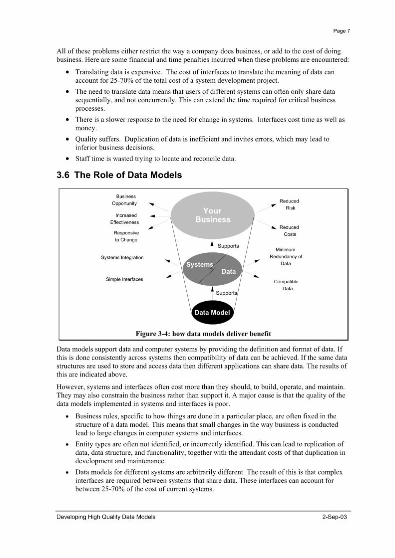
Figure 3-4: how data models deliver benefit
Data models support data and computer systems by providing the definition and format of data. If this is done consistently across systems then compatibility of data can be achieved. If the same data structures are used to store and access data then different applications can share data. The results of this are indicated above.
However, systems and interfaces often cost more than they should, to build, operate, and maintain. They may also constrain the business rather than support it. A major cause is that the quality of the data models implemented in systems and interfaces is poor.
• Business rules, specific to how things are done in a particular place, are often fixed in the structure of a data model. This means that small changes in the way business is conducted lead to large changes in computer systems and interfaces.
• Entity types are often not identified, or incorrectly identified. This can lead to replication of data, data structure, and functionality, together with the attendant costs of that duplication in development and maintenance.
• Data models for different systems are arbitrarily different. The result of this is that complex interfaces are required between systems that share data. These interfaces can account for between 25-70% of the cost of current systems.
Developing High Quality Data Models 2-Sep-03

Page 8
• Data cannot be shared electronically with customers and suppliers, because the structure and meaning of data has not been standardised. For example, engineering design data and drawings for process plant are still sometimes exchanged on paper.
The reason for these problems is a lack of standards that will ensure that data models will both meet business needs and be consistent.
2-Sep-03 Developing High Quality Data Models

Page 9
4. The Need for Standards
4.1 Background
Before going further it is worth remembering that all models are a limited representation of something else, as illustrated in Figure 4-1. The representation will have a particular purpose in mind, and will focus on representing those aspects that are important to that purpose.
A data model defines the structure and meaning of data. This document is primarily concerned with data models that enable the reuse of data by different applications, either by integrating and sharing data within a single database, or exchanging data by some other means such as a file transfer.
m/v Crow's Nest
Scale 1:50010,000 tons Shipcraft & Co.
Figure 4-1: A model is a limited representation of some important aspects of something
used for a purpose
4.2 The ANSI/SPARC Architecture
The technique of data modelling can be used for many purposes. This is illustrated in Figure 4-2 below following the architecture developed by the Standards Planning and Requirements Committee (SPARC) of the American National Standards Institute (ANSI) on Computers and Information Processing (ANSI/X3) and first published in 1975. This shows that a data model can be an external model (or view), a conceptual model, or a physical model. This is not the only way to look at data models, but it is a useful way, particularly when comparing models.
Developing High Quality Data Models 2-Sep-03

Page 10
ES1 ES2 ES3 ES4
IS1 IS2
External Models or Views
Physical Models
Conceptual Model
External Level
Conceptual Level
Physical Level
Figure 4-2: The ANSI/SPARC three level architecture.
An external model (or view) looks at the world from a particular perspective, for a particular purpose. There are many possible external views of the world: they may overlap, and do not have to be compatible. In particular, external views are an appropriate place to hold the data requirements for a particular business context and the rules that apply to it. The data models of most applications today take a view of the world from the perspective of that application, and so are external models.
A conceptual model is an underlying or neutral model that is capable of supporting any valid (and perhaps changing) external view that falls within its scope. As a result, a conceptual data model is not an appropriate place to hold rules that may change. A corporate data model should be an example of a conceptual model. To be able to integrate data from different sources, a data model must be conceptual relative to the source data models.
A physical model represents a way in which data is physically stored. There may be many valid physical models for a conceptual model. The requirement is that a physical model must be able to support the conceptual model.
Data models at each of these levels are useful and important, and can be represented using the entity relationship modelling technique. However, because they can all be represented in the same way it is important to distinguish at which level a model is.
The most important level of model for tackling the problems of data sharing and exchange is the conceptual model. This is the level that is the basis for sharing between different parties and is the level primarily addressed in this document.
4.3 Requirements for Data Models
From the business requirements outlined above the following requirements for data models are derived. They should:
√ meet the data requirement, √ be clear and unambiguous to all (not just the authors), √ be stable in the face of changing data requirements, √ be flexible in the face of changing business practices, √ be reusable by others,
2-Sep-03 Developing High Quality Data Models
Page 11
√ be consistent with other models covering the same scope, and √ be able to reconcile conflicting data models.
In addition, it should be possible to develop data models quickly.
4.4 Data Modelling Today
ActivityModel
Detailed DataRequirements
TechnicalEnvironment
PerformanceConsiderations
BusinessData
Create/UpdateLogical Data
Model
Create/UpdatePhysical Data
Model
Create/UpdateData
Data
Entities/SubtypesAttributesRelationshipsIntegrity Rules
Conceptual Data Model
TablesColumnsKeys/IndiciesTriggers
Physical Data Model
Figure 4-3: Data Modelling Today.
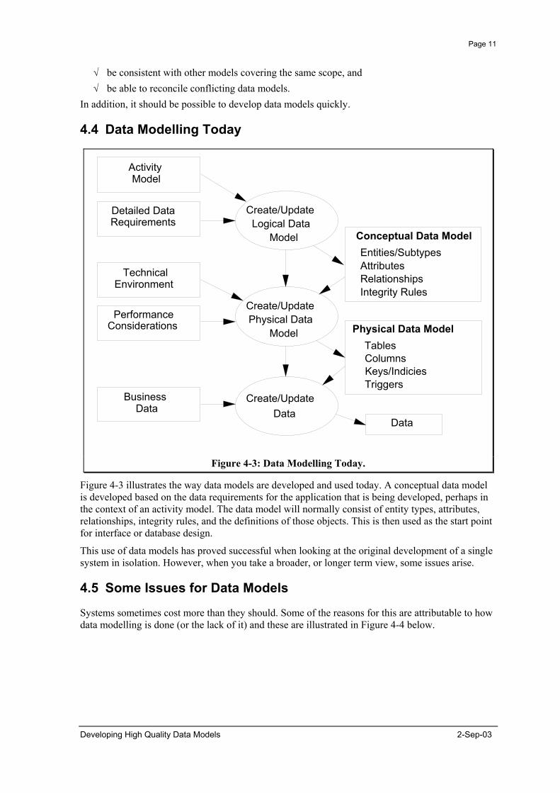
Figure 4-3 illustrates the way data models are developed and used today. A conceptual data model is developed based on the data requirements for the application that is being developed, perhaps in the context of an activity model. The data model will normally consist of entity types, attributes, relationships, integrity rules, and the definitions of those objects. This is then used as the start point for interface or database design.
This use of data models has proved successful when looking at the original development of a single system in isolation. However, when you take a broader, or longer term view, some issues arise.
4.5 Some Issues for Data Models
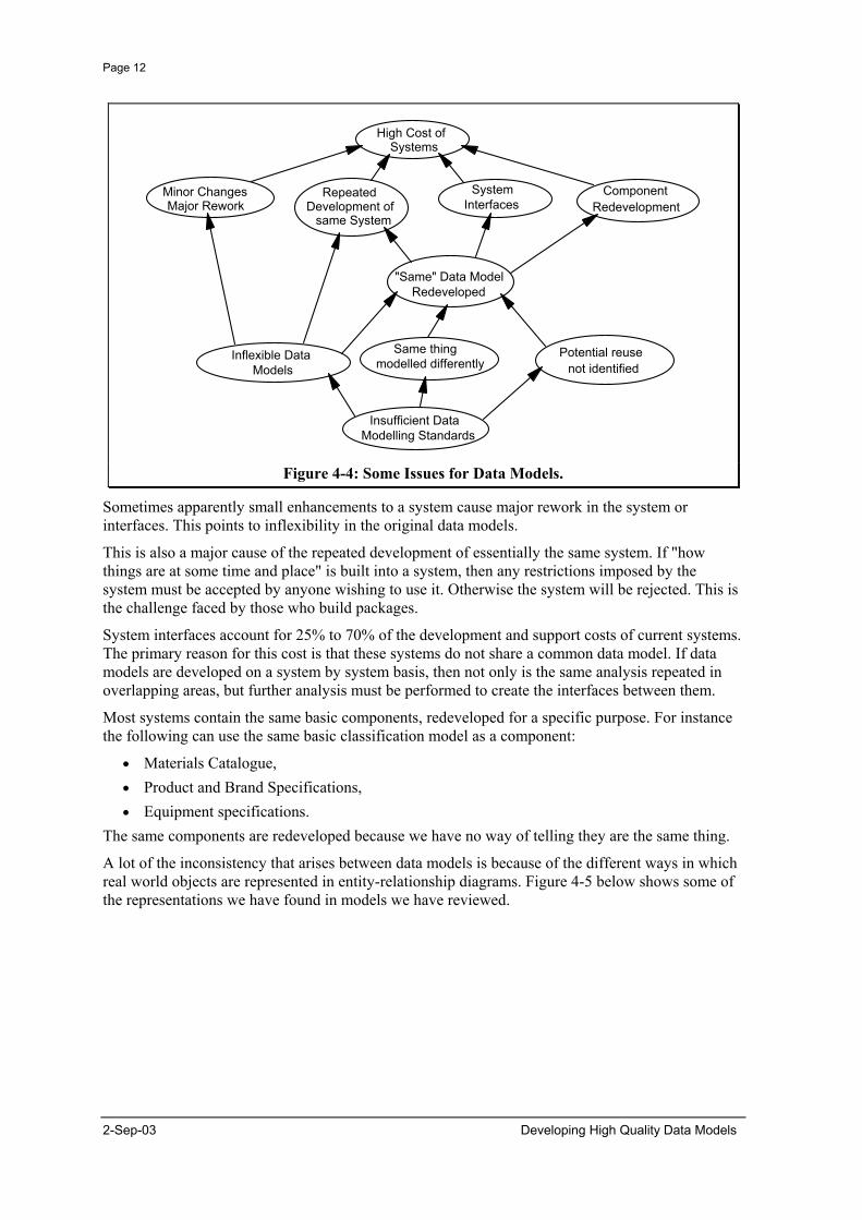
Systems sometimes cost more than they should. Some of the reasons for this are attributable to how data modelling is done (or the lack of it) and these are illustrated in Figure 4-4 below.
Developing High Quality Data Models 2-Sep-03
Page 12
High Cost of Systems
Repeated Development of
same System
Minor Changes Major Rework
Component Redevelopment
System Interfaces
Inflexible Data Models
Potential reuse not identified
Insufficient Data Modelling Standards
"Same" Data Model Redeveloped
Same thing modelled differently
Figure 4-4: Some Issues for Data Models.
Sometimes apparently small enhancements to a system cause major rework in the system or interfaces. This points to inflexibility in the original data models.
This is also a major cause of the repeated development of essentially the same system. If "how things are at some time and place" is built into a system, then any restrictions imposed by the system must be accepted by anyone wishing to use it. Otherwise the system will be rejected. This is the challenge faced by those who build packages.
System interfaces account for 25% to 70% of the development and support costs of current systems. The primary reason for this cost is that these systems do not share a common data model. If data models are developed on a system by system basis, then not only is the same analysis repeated in overlapping areas, but further analysis must be performed to create the interfaces between them.
Most systems contain the same basic components, redeveloped for a specific purpose. For instance the following can use the same basic classification model as a component:
• Materials Catalogue, • Product and Brand Specifications, • Equipment specifications.
The same components are redeveloped because we have no way of telling they are the same thing.
A lot of the inconsistency that arises between data models is because of the different ways in which real world objects are represented in entity-relationship diagrams. Figure 4-5 below shows some of the representations we have found in models we have reviewed.
2-Sep-03 Developing High Quality Data Models

Page 13
Real World Object
Activities / Transactions/Associations / Event-Effects
Classes
Materials /Tokens
Roles/Involvements
Basic Data Types
Representation
Entity Types
Relationships
Attributes
Figure 4-5: Some mappings of real world objects to entity-relationship concepts today.
If the same concepts are modelled in different ways, then there is no way that you can expect that different models of the same thing will look the same.
The differences between how things get modelled is caused by building models that have a specific viewpoint, or specific rules and constraints built in. Since others may have different rules or a different view point, these are things that we know we don't want in a conceptual data model. Thus we have to understand how to represent the world in a neutral way so the resulting models are flexible and stable.
4.6 Required Standards
The underlying reason for these problems is a lack of data modelling standards.
EXTERNAL INPUTS
ACTIVITY DELIVERABLE STANDARDS
BusinessModel
Detailed DataRequirements
TechnicalEnvironment
PerformanceConsiderations
BusinessData
Create/UpdateLogical Data
Model
Create/UpdatePhysical Data
Model
Create/UpdateData Data
StandardContext
AnalysisStandards
Naming Standards
StandardAttribute Formats
Standard Data
Entities/SubtypesAttributesRelationshipsIntegrity Rules
TablesColumnsKeys/IndiciesTriggers
Conceptual Data Model
Physical Data Model
Figure 4-6: Standards required for high quality data models.
Figure 4-6 identifies standards that are needed so that data and data models can be shared rather than redeveloped. This document presents the second of these, analysis standards.
Developing High Quality Data Models 2-Sep-03
Page 14
4.7 Principles for Conceptual Data Models
The principles presented here have been discovered, not invented, as supporting the development of data models that meet the requirements in section 4.3. Other requirements might give rise to other principles. They represent good data modelling practice, which can be applied to a wide range of entity relationship or object oriented modelling approaches (e.g. diagramming conventions).
2-Sep-03 Developing High Quality Data Models

Page 15
5. Principles for Attributes
Data modelling practitioners have traditionally aimed at a third normal form (3NF) model within the context of the data requirement for the current application. This leaves many attributes representing relationships to real world objects that should be recognised as entity types. We call entity types with attributes that hide other entity types complex entity types.
5.1 An Example - Sales Product
Figure 5-1 gives an example of a complex entity type1.
Sales_product
• product_code• product_name• stock_item_code• packing• unit_of_measure• list_price• list_price_uom
Figure 5-1: A complex entity type.
The clue to look for is a relatively large number of attributes, or unexpected attributes. This means that a particular business view is being modelled rather than the underlying nature of the problem.
The process that is followed in resolving a complex entity type is to examine each attribute in turn, discover what it means, and determine whether it is really an attribute of the entity type in question. The key question is does the attribute directly describe the entity type, or does it represent a relationship to another entity type which is perhaps unrecognised.
First look at the entity type. What is it about? Sales Product is a classification of the products, materials, and possibly services we sell.
The first attribute is Product Code. This appears to be the identifier for the Sales Product and is appropriate. Likewise the Product Name/Brand appears to be a textual description of the Sales Product and is also appropriate.
However, this is not the case for Stock Item Code. "Code" is a word which is usually used in Attributes that are entity type identifiers. So if Product Code is the identifier for Sales Product, then what is Stock Item Code the identifier for?
If you are familiar with Sales and Stock systems you will understand that there are two different views of product that are important. One is the view of what is stocked or made, the other is the view of what is sold. This is necessary because the same product is sometimes sold under different names into different markets, or the same Sales Product is supplied from Products with different specifications. Now the Sales Product entity type is clearly the view of what is being sold, however,
1 All data model diagram examples use the EXPRESS-G notation. EXPRESS-G is defined in ISO 10303-11. A brief
tutorial on EXPRESS-G diagrams is given in section 10 of this document. In some cases, the “verbosity” of the EXPRESS-G notation for attributes makes it easier to list attributes within the box that represents the entity data type. This has been done in this example.
Developing High Quality Data Models 2-Sep-03
Page 16
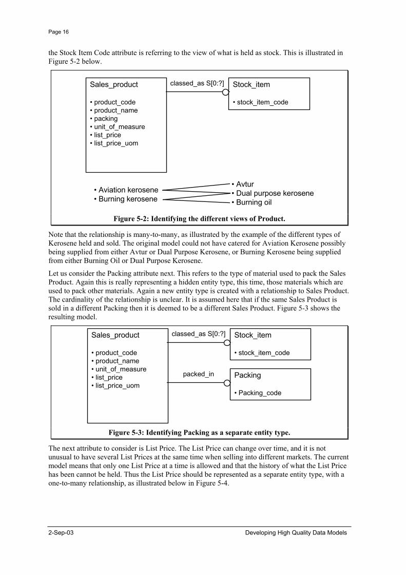
the Stock Item Code attribute is referring to the view of what is held as stock. This is illustrated in Figure 5-2 below.
Sales_product
• product_code• product_name• packing• unit_of_measure• list_price• list_price_uom
Stock_item
• stock_item_code
classed_as S[0:?]
• Aviation kerosene• Burning kerosene
• Avtur• Dual purpose kerosene• Burning oil
Figure 5-2: Identifying the different views of Product.
Note that the relationship is many-to-many, as illustrated by the example of the different types of Kerosene held and sold. The original model could not have catered for Aviation Kerosene possibly being supplied from either Avtur or Dual Purpose Kerosene, or Burning Kerosene being supplied from either Burning Oil or Dual Purpose Kerosene.
Let us consider the Packing attribute next. This refers to the type of material used to pack the Sales Product. Again this is really representing a hidden entity type, this time, those materials which are used to pack other materials. Again a new entity type is created with a relationship to Sales Product. The cardinality of the relationship is unclear. It is assumed here that if the same Sales Product is sold in a different Packing then it is deemed to be a different Sales Product. Figure 5-3 shows the resulting model.
Sales_product
• product_code• product_name• unit_of_measure• list_price• list_price_uom
Stock_item
• stock_item_code
classed_as S[0:?]
Packing
• Packing_code
packed_in
Figure 5-3: Identifying Packing as a separate entity type.
The next attribute to consider is List Price. The List Price can change over time, and it is not unusual to have several List Prices at the same time when selling into different markets. The current model means that only one List Price at a time is allowed and that the history of what the List Price has been cannot be held. Thus the List Price should be represented as a separate entity type, with a one-to-many relationship, as illustrated below in Figure 5-4.
2-Sep-03 Developing High Quality Data Models
Page 17
Sales_product
• product_code• product_name• unit_of_measure
Stock_item
• stock_item_code
classed_as S[0:?]
Packing
• Packing_code
List Price
• List_price_id• List_price• List_price_uom• Start_date• End_date
Missingattributes
packed_in
price_of
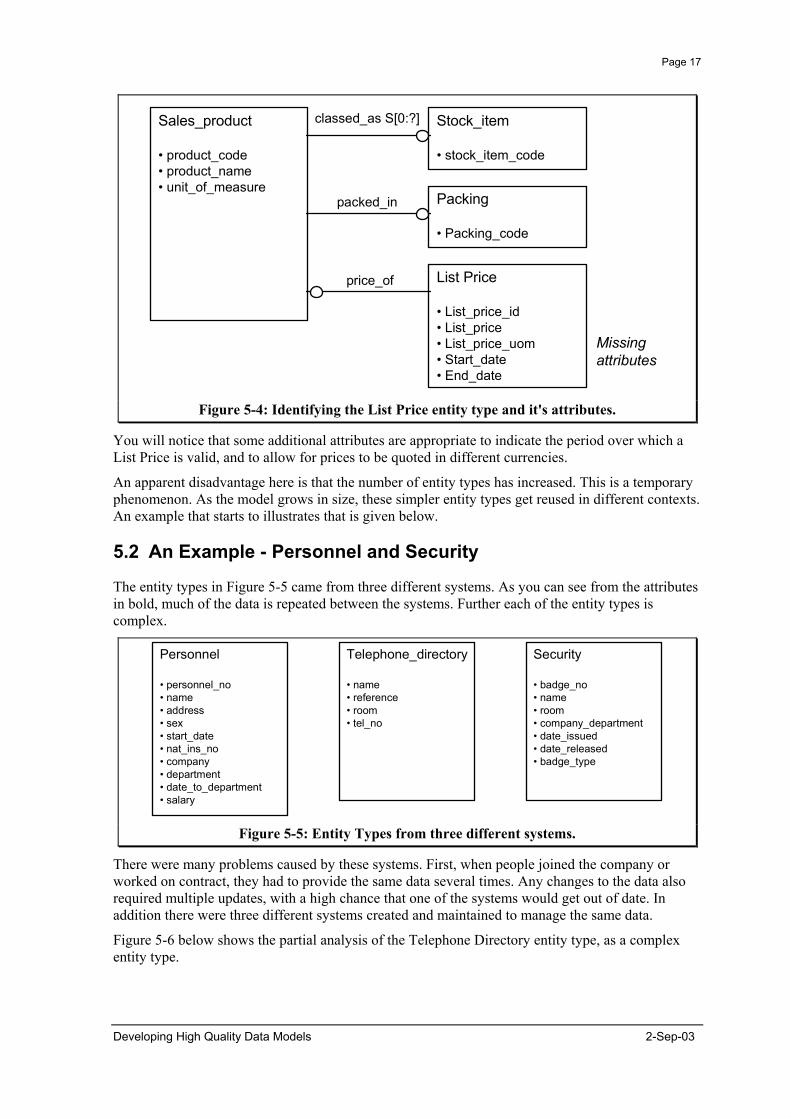
Figure 5-4: Identifying the List Price entity type and it's attributes.
You will notice that some additional attributes are appropriate to indicate the period over which a List Price is valid, and to allow for prices to be quoted in different currencies.
An apparent disadvantage here is that the number of entity types has increased. This is a temporary phenomenon. As the model grows in size, these simpler entity types get reused in different contexts. An example that starts to illustrates that is given below.
5.2 An Example - Personnel and Security
The entity types in Figure 5-5 came from three different systems. As you can see from the attributes in bold, much of the data is repeated between the systems. Further each of the entity types is complex.
Telephone_directory
• name• reference• room• tel_no
Security
• badge_no• name• room• company_department• date_issued• date_released• badge_type
Personnel
• personnel_no• name• address• sex• start_date• nat_ins_no• company• department• date_to_department• salary
Figure 5-5: Entity Types from three different systems.
There were many problems caused by these systems. First, when people joined the company or worked on contract, they had to provide the same data several times. Any changes to the data also required multiple updates, with a high chance that one of the systems would get out of date. In addition there were three different systems created and maintained to manage the same data.
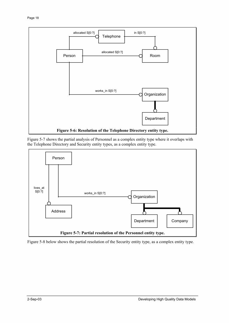
Figure 5-6 below shows the partial analysis of the Telephone Directory entity type, as a complex entity type.
Developing High Quality Data Models 2-Sep-03
Page 18
Telephone
Person Room
Organization
Department
allocated S[0:?] in S[0:?]
allocated S[0:?]
works_in S[0:?]
Figure 5-6: Resolution of the Telephone Directory entity type.
Figure 5-7 shows the partial analysis of Personnel as a complex entity type where it overlaps with the Telephone Directory and Security entity types, as a complex entity type.
Address
lives_atS[0:?]
Person
Organization
Department
works_in S[0:?]
Company
Figure 5-7: Partial resolution of the Personnel entity type.
Figure 5-8 below shows the partial resolution of the Security entity type, as a complex entity type.
2-Sep-03 Developing High Quality Data Models
Page 19
Person
Organization
Department
works_in S[0:?]
Company
Roomallocated S[0:?]
Security_badge
issued_with S[0:?]
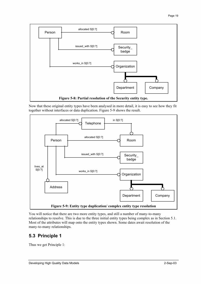
Figure 5-8: Partial resolution of the Security entity type.
Now that these original entity types have been analysed in more detail, it is easy to see how they fit together without interfaces or data duplication. Figure 5-9 shows the result.
Address
lives_atS[0:?]
Person
Organization
Department
works_in S[0:?]
Company
Roomallocated S[0:?]
Security_badge
issued_with S[0:?]
Telephoneallocated S[0:?] in S[0:?]
Figure 5-9: Entity type duplication/ complex entity type resolution
You will notice that there are two more entity types, and still a number of many-to-many relationships to resolve. This is due to the three initial entity types being complex as in Section 5.1. Most of the attributes will map onto the entity types shown. Some dates await resolution of the many-to-many relationships.
5.3 Principle 1
Thus we get Principle 1:
Developing High Quality Data Models 2-Sep-03

Page 20
1. Candidate attributes should be treated as representing relationships to other entity types.
5.4 Identification
There are two levels at which identification of things is important:
1. internal, within a file or database, and 2. external, across a number of independently managed files, databases, or organisations.
5.5 Internal Identification
The purpose of an internal identifier is for the efficient and effective management of data about something by computer systems. Within a database or file it is important that each object represented has a surrogate, so that information about the object can be grouped together. In a database this might be provided by an attribute. In a STEP Part 21 file, this is provided automatically.
Relationships should not be used as part of the internal identifier because this makes the existence of the object dependent on the relationship, and hence it makes existence of information about the object dependent on knowledge of information about the object it is related to. Even where there is real world dependence, it is unusual for it to translate into data dependence, e.g. because I must have two parents does not mean that you must know who my parents are to know me.
5.6 The Trap - Inappropriate Choice of Unique Identifier.
In the real world things don't necessarily come with a convenient number stamped on them for identification. Sometimes we do gives things an identifier, but often we refer to things indirectly "the one I ordered last week" and rely on the context. There is a temptation to carry over this indirect identification of objects through the relationships or attributes they have into data models where it can cause problems.
Consequences Imposing restrictions through the data structure means: • Arbitrary or inappropriate restrictions are placed on the data that can be held. • Fudge or false data may be introduced to overcome the restrictions in the data
structure. This may have to be programmed around. • The entity type will only work within the context defined. A change in business
rules may require a change in the database structure. • The resultant system is harder to share. Failing to correctly recognise entity types means: • The same data structures may be replicated.
5.7 An Example - Ship
Figure 5-10 shows an example of this. It is in fact the same example as above.
2-Sep-03 Developing High Quality Data Models
Page 21
Ship
Port
Name
registered_at*
registered_under*
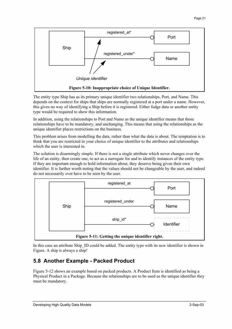
Unique identifier Figure 5-10: Inappropriate choice of Unique Identifier.
The entity type Ship has as its primary unique identifier two relationships, Port, and Name. This depends on the context for ships that ships are normally registered at a port under a name. However, this gives no way of identifying a Ship before it is registered. Either fudge data or another entity type would be required to show this information.
In addition, using the relationships to Port and Name as the unique identifier means that those relationships have to be mandatory, and unchanging. This means that using the relationships as the unique identifier places restrictions on the business.
This problem arises from modelling the data, rather than what the data is about. The temptation is to think that you are restricted in your choice of unique identifier to the attributes and relationships which the user is interested in.
The solution is disarmingly simple. If there is not a single attribute which never changes over the life of an entity, then create one, to act as a surrogate for and to identify instances of the entity type. If they are important enough to hold information about, they deserve being given their own identifier. It is further worth noting that the values should not be changeable by the user, and indeed do not necessarily ever have to be seen by the user.
Ship
Port
Name
registered_at
registered_under
Identifiership_id*
Figure 5-11: Getting the unique identifier right.
In this case an attribute Ship_ID could be added. The entity type with its new identifier is shown in Figure. A ship is always a ship!
5.8 Another Example - Packed Product
Figure 5-12 shows an example based on packed products. A Product Item is identified as being a Physical Product in a Package. Because the relationships are to be used as the unique identifier they must be mandatory.
Developing High Quality Data Models 2-Sep-03

Page 22
Product_item
Physical_product
Package
contents*
container*
“Air”
“Bulk”
Unique identifier Figure 5-12: Using relationships as the unique identifier.
The problems caused by this choice of unique identifier are those that result from the restrictions the necessary cardinality places on the business. In this case fudge and false data need to be introduced.
This arises because in the description of the entity types it is explained that sometimes a Physical Product is sold in bulk form, without a package, and sometimes Packages are moved or sold without any contents. To get round this a Physical Product of Air was introduced, and a Package of Bulk. This works around the fact that the cardinalities of the two relationship are incorrect. They have been made mandatory, when they should be optional.
Introducing the fudge data to overcome the incorrect cardinalities can have expensive consequences. Because Air is not really a Physical Product it can become necessary to introduce into code that uses the table things like "for all the Physical Products .. except Air ..". This is expensive to design, build, check and maintain. It is also unnecessary.
The solution is to create an attribute specifically to be the identifier of a Product Item. This then means that you do not have to make the relationships mandatory when they are not. The result is shown in Figure 5-13.
Product_item
Physical_product
Package
contents
container
Identifierproduct_item_id*
Figure 5-13: Using a special attribute as the unique identifier.
5.9 Principle 2
2. Entities and records should have an internal identifier within a database or exchange file. These should be artificial and managed to be unique.
Relationships should not be used as part of the internal identifier. Artificial means that the identifier has no meaning to the user, and is arbitrary (e.g. the next number in a list). It also means that no program would be able to analyse the identifier and make some judgement on what sort of thing it represented.
2-Sep-03 Developing High Quality Data Models
Page 23
5.10 External Identification
The purpose of external identification is so that computer systems, people, and organisations can know what information is about in a broader context than the local computer system or organisation. This is particularly important for the integration of data from different systems. Take for example the unit of measure kg. If one system calls it "kg", and another "kilograms", then they will not be able to exchange data. A weight of 30 kg in the first system would be meaningless to the second system.
The first thing to understand about external identifiers is that there can be many of them. For example, I have an employee number, a driving licence no, a National Insurance number, a National Health Number etc. The next thing is to understand that each of these identifiers is issued by an authority, which manages them so that an identifier is only issued for one person, and that a person only has one identifier (at a time).
The consequence of this is that external identification is best dealt with as part of the overall data model, and so is not dealt with further here.
5.11 Record Identifiers
We sometimes forget that records are things too, which we may wish to manage, or authorise for a particular use. Some DBMS's give each record a record identifier, which is not seen by the user. This identifies a particular record (within the DBMS instance) and is not a surrogate for the object itself. Both are needed for proper management of data.
5.12 Expected Attributes
The following are attributes that would be expected.
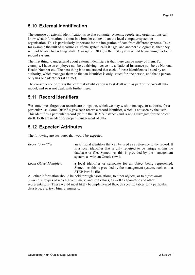
Record Identifier: an artificial identifier that can be used as a reference to the record. It is a local identifier that is only required to be unique within the database or file. Sometimes this is provided by the management system, as with an Oracle row id.
Local Object Identifier: a local identifier or surrogate for an object being represented. Sometimes this is provided by the management system, such as in a STEP Part 21 file.
All other information should be held through associations, to other objects, or to information content, subtypes of which give numeric and text values, as well as geometric and other representations. These would most likely be implemented through specific tables for a particular data type, e.g. text, binary, numeric.
Developing High Quality Data Models 2-Sep-03

Page 24
6. Principles for Relationships
6.1 Relationships and Associations
In order to clarify the discussion, I would like to start by distinguishing between how I will use the terms "relationship" and "association". I shall use the term "association" to represent what one thing has to do with another. On the other hand, in the context of entity-relationship modelling, a relationship is the line that links one entity type to another. It can be used to represent a concept, such as an association.
6.2 A Bad Example - Batch and Product Type
Understanding how to represent the world is best done by looking at an example. In Figure 6-1 below I have reproduced the model used to explain the EXPRESS-G notation for entity-relationship diagrams.
Batch Product_typeclassified_as
(INV) classifies S[0:?]
exactly one
Figure 6-1: An example of a relationship.
This model is already better than many you will see. Often relationships are not named, or are given meaningless names like "has" and "for". The key thing to notice is that the entity types at both ends of the relationship are independent entity types. That is, they exist independently of the things around them. A batch is some stuff in a tank, and a product type is a specification to which we try to make product, e.g. unleaded mogas. Inherently, we can have stuff sitting in tanks without knowing what type of thing it is, and we can have types of thing we would like to have, without actually having any.
The data model in Figure 4.9 tells a different story. It says that I can't have a batch unless it is classified. It also says that a batch can only be classified as one product type, and it says that the classification can never change (or I lose the history of how it was classified if I do). None of these things are generally true, even if they are appropriate in some special circumstances. Thus this model can restrict the business, and lose history. This is generally true for all relationships between independent entity types.
Representing activities or associations as relationships may mean that restrictions are placed on users as to what data can be held. This is inappropriate in a conceptual model. The fact is that associations are passive links between entity types, and as such are things of potential interest in their own right. In particular they have attributes, such as the date the association was created, and the date it was terminated. Associations are caused and terminated by activities. Similarly, an activity is something happening, and has attributes such as the start date/time and end date/time of the activity, and relationships such as who or what did it.
2-Sep-03 Developing High Quality Data Models
Page 25
6.3 A Second Example - Packed Products
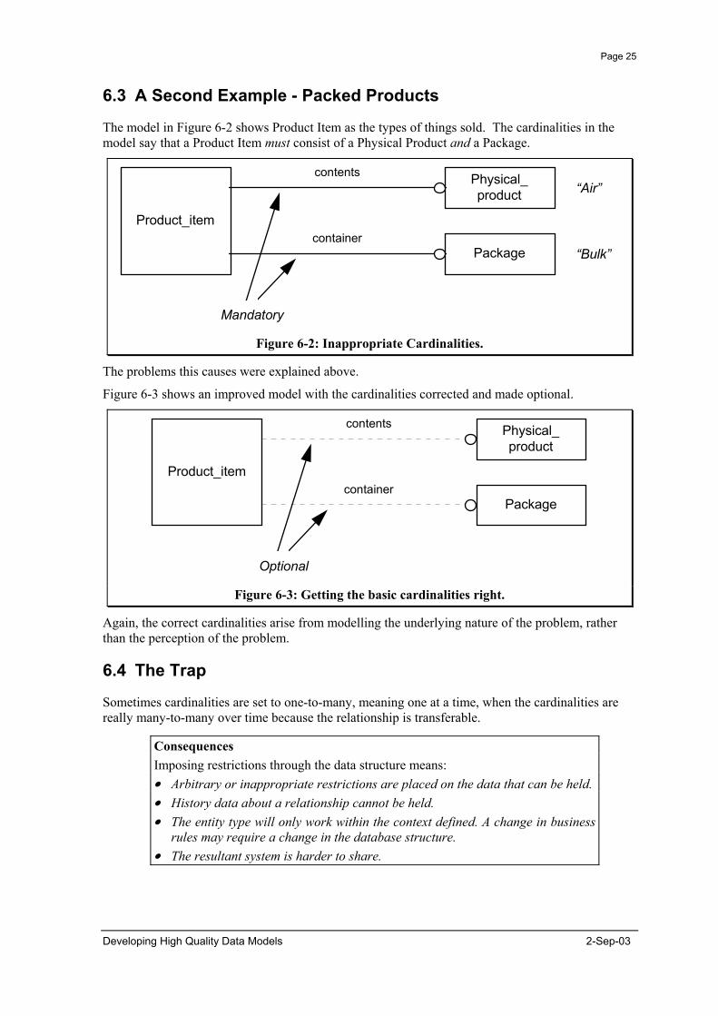
The model in Figure 6-2 shows Product Item as the types of things sold. The cardinalities in the model say that a Product Item must consist of a Physical Product and a Package.
Product_item
Physical_product
Package
contents
container
“Air”
“Bulk”
Mandatory
Product_item
Physical_product
Package
contents
container
Optional
Figure 6-2: Inappropriate Cardinalities.
The problems this causes were explained above.
Figure 6-3 shows an improved model with the cardinalities corrected and made optional.
Figure 6-3: Getting the basic cardinalities right.
Again, the correct cardinalities arise from modelling the underlying nature of the problem, rather than the perception of the problem.
6.4 The Trap
Sometimes cardinalities are set to one-to-many, meaning one at a time, when the cardinalities are really many-to-many over time because the relationship is transferable.
Consequences Imposing restrictions through the data structure means: • Arbitrary or inappropriate restrictions are placed on the data that can be held. • History data about a relationship cannot be held. • The entity type will only work within the context defined. A change in business
rules may require a change in the database structure. • The resultant system is harder to share.
Developing High Quality Data Models 2-Sep-03

Page 26
6.5 An Example - Ship
Figure 6-4 shows that a Ship is registered at one Port and only one Port, under one name and only one name.
Ship
Port
Name
registered_at
registered_under
Transferable relationships Figure 6-4: Transferable relationships
However, what happens if you re-register a Ship? How do you know what it was previously sailing as? The same applies to the Name. If it changes you do not know that it refers to a vessel that you had blacklisted, or was an old friend.
Ship
Port
Name
registered_at S[0:?]
registered_under S[0:?]
Figure 6-5: Correct cardinalities for transferable relationships.
Figure 6-5 shows the correct relationship cardinalities as many-to-many, which recognises that a one-at-a-time relationship is potentially many-to-many over time. The problem was caused by modelling a business perspective, that we normally refer to a ship by its name and port of registration, rather than looking for what underlies that view.
Resolving the many-to-many relationships into entity types leads to a model as illustrated in Figure 6-6.
2-Sep-03 Developing High Quality Data Models
Page 27
Port
Ship
Name
Ship_registered_at_port
Ship_registered_under_name
at
registered
registered
under
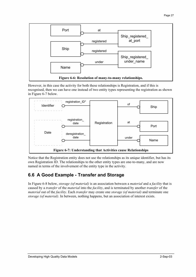
Figure 6-6: Resolution of many-to-many relationships.
However, in this case the activity for both these relationships is Registration, and if this is recognised, then we can have one instead of two entity types representing the registration as shown in Figure 6-7 below.
Port
Ship
Name
Registration
of
at
under
Identifier
Date
registration_ID*
registration_date
deregistration_date
Figure 6-7: Understanding that Activities cause Relationships
Notice that the Registration entity does not use the relationships as its unique identifier, but has its own Registration ID. The relationships to the other entity types are one-to-many, and are now named in terms of the involvement of the entity type in the activity.
6.6 A Good Example - Transfer and Storage
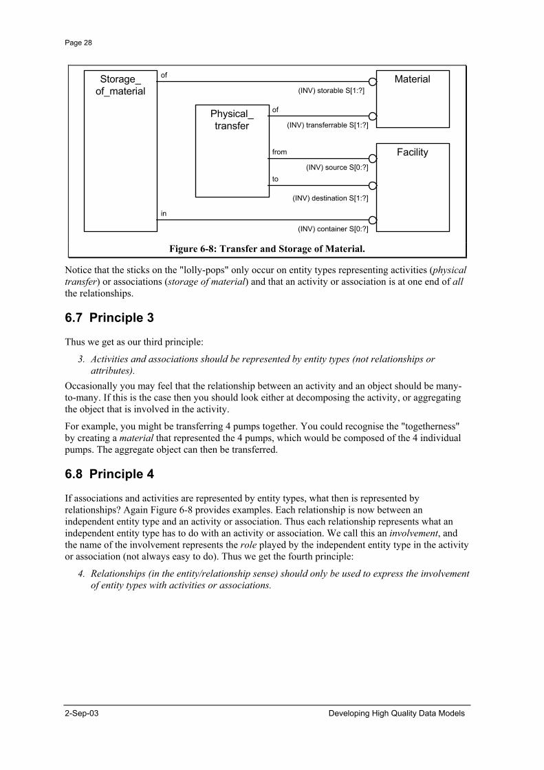
In Figure 6-8 below, storage (of material) is an association between a material and a facility that is caused by a transfer of the material into the facility, and is terminated by another transfer of the material out of the facility. Each transfer may create one storage (of material) and terminate one storage (of material). In between, nothing happens, but an association of interest exists.
Developing High Quality Data Models 2-Sep-03
Page 28
Storage_of_material
Material
Facility
Physical_transfer
of
of
from
to
in
(INV) storable S[1:?]
(INV) transferrable S[1:?]
(INV) source S[0:?]
(INV) destination S[1:?]
(INV) container S[0:?] Figure 6-8: Transfer and Storage of Material.
Notice that the sticks on the "lolly-pops" only occur on entity types representing activities (physical transfer) or associations (storage of material) and that an activity or association is at one end of all the relationships.
6.7 Principle 3
Thus we get as our third principle:
3. Activities and associations should be represented by entity types (not relationships or attributes).
Occasionally you may feel that the relationship between an activity and an object should be many-to-many. If this is the case then you should look either at decomposing the activity, or aggregating the object that is involved in the activity.
For example, you might be transferring 4 pumps together. You could recognise the "togetherness" by creating a material that represented the 4 pumps, which would be composed of the 4 individual pumps. The aggregate object can then be transferred.
6.8 Principle 4
If associations and activities are represented by entity types, what then is represented by relationships? Again Figure 6-8 provides examples. Each relationship is now between an independent entity type and an activity or association. Thus each relationship represents what an independent entity type has to do with an activity or association. We call this an involvement, and the name of the involvement represents the role played by the independent entity type in the activity or association (not always easy to do). Thus we get the fourth principle:
4. Relationships (in the entity/relationship sense) should only be used to express the involvement of entity types with activities or associations.
2-Sep-03 Developing High Quality Data Models

Page 29
7. Principles for Entity Types
One of the biggest problems in managing data is identifying what is being talked about. That is, what is a sound basis for identifying and naming entity types? In order to be able to hold data about something we need to identify what it is. In order to be able to share data about something, we need to have a consistent view of what it is about, independent of the context for a particular use.
When data is context dependent, then it means that the data could mean something else in another context. In order to make such data independent of its context, the context must be made an explicit part of the data, rather than something assumed.
Two ways in which things can go wrong are given below.
7.1 An Example - Combined Entity Types
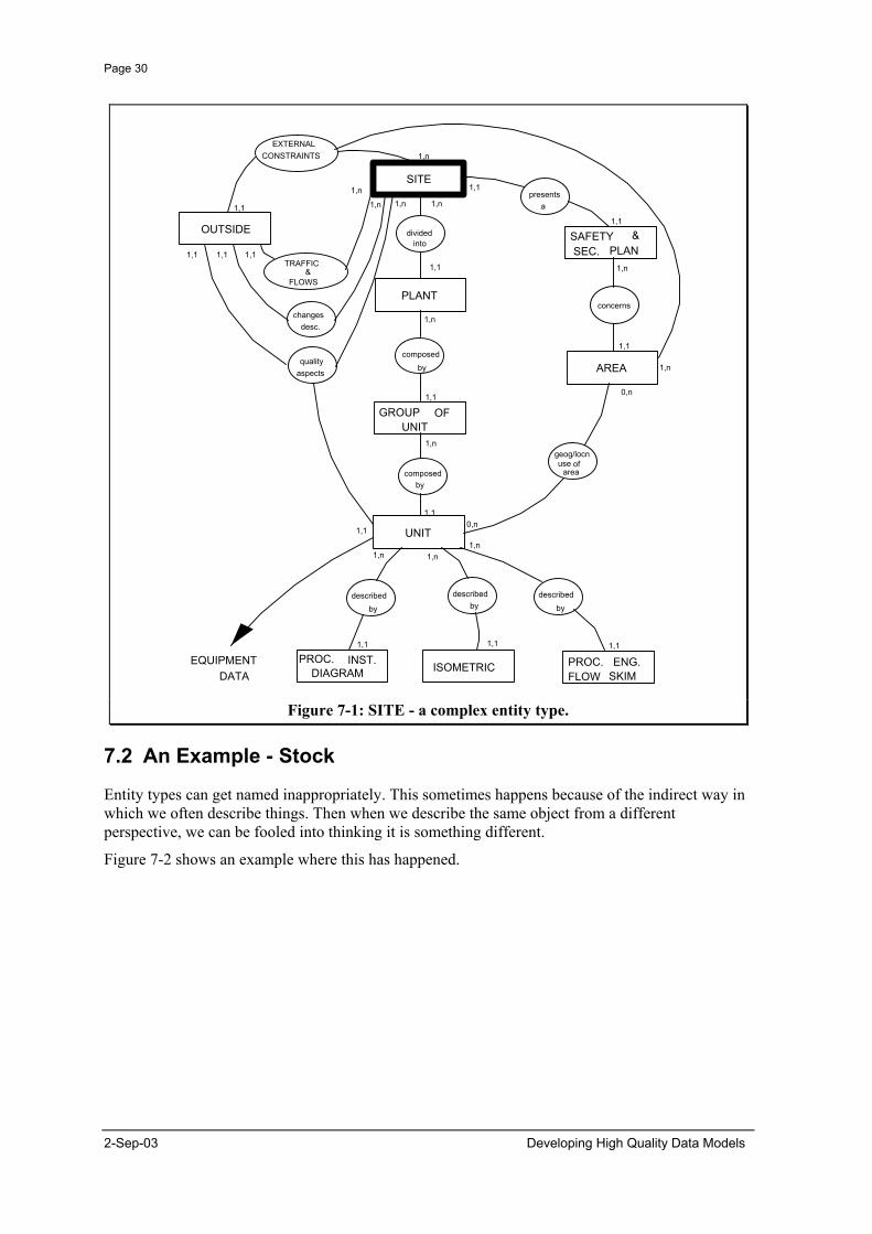
Figure 7-1 shows a data model using the 'Merise' notation that focuses on the entity type site. When you look at the relationships that site has to other entity types it becomes clear that it represents many things.
First, site can be decomposed into a number of plants which in turn can be decomposed into a number of groups of units, which can be decomposed into units. This is the concept known as facility, which is about the purpose and service provided by something.
Secondly site presents a safety and security plan. Clearly, this is about the organisation responsible for the facility, rather than the facility itself.
Finally, there are traffic & flows with outside. This suggests that location is also wrapped up in site.
This combination of concepts was possible because in the place where this model came from there was a 1:1:1 relationship between these concepts that allowed them to be modelled together, and the word site was sufficiently ambiguous that it could be used in the context of each of them. Combining these concepts gives a model which others may not be able to use, and which may not apply given changing circumstances.
Developing High Quality Data Models 2-Sep-03
Page 30
SITE
PLANT
GROUP OF UNIT
SAFETY &SEC. PLAN
AREA
UNIT
ISOMETRIC PROC. ENG.FLOW SKIM
PROC. INST.DIAGRAM
OUTSIDE
EXTERNALCONSTRAINTS
TRAFFIC &
FLOWS
dividedinto
presentsa
concernschanges
desc.
qualityaspects
composedby
composedby
geog/locnuse of
area
describedby
describedby
describedby
1,1 1,1 1,1
1,1
1,1
1,n 1,n1,n
0,n
EQUIPMENTDATA
1,n
1,1 0,n
1,1
1,n
1,11,1
1,n
1,1 1,n
1,1
1,11,1
1,1
1,n1,n1,n
1,n
1,n
Figure 7-1: SITE - a complex entity type.
7.2 An Example - Stock
Entity types can get named inappropriately. This sometimes happens because of the indirect way in which we often describe things. Then when we describe the same object from a different perspective, we can be fooled into thinking it is something different.
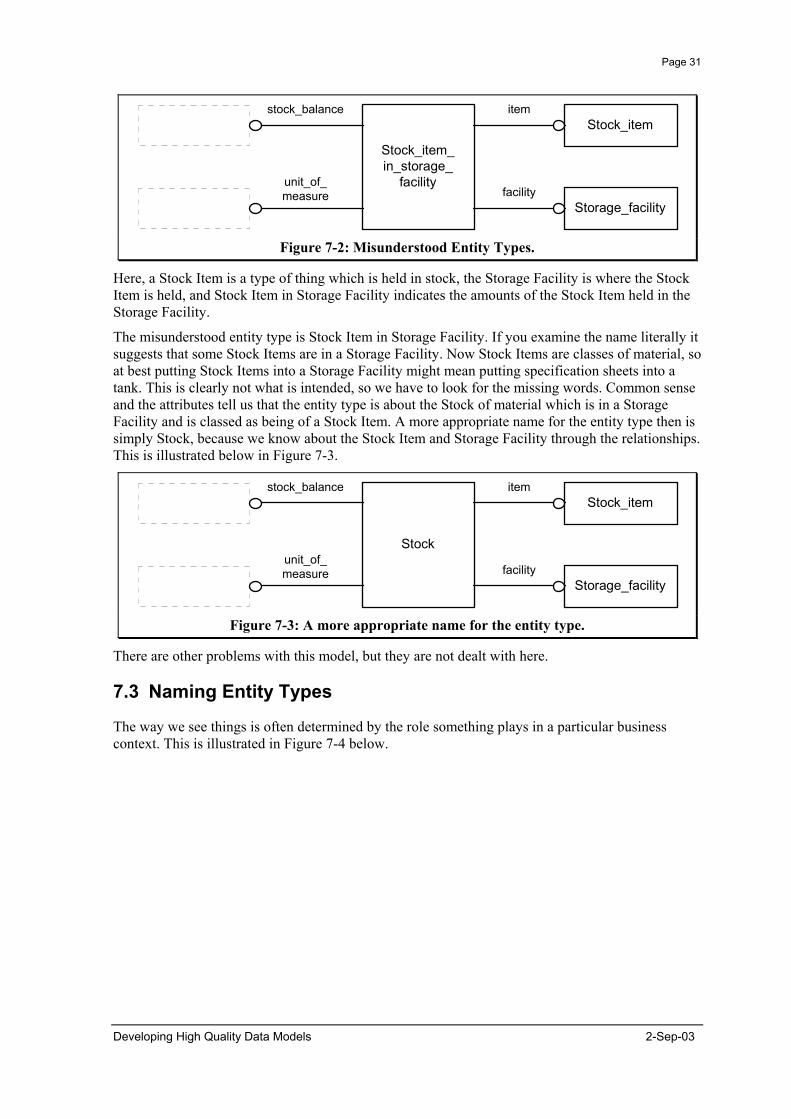
Figure 7-2 shows an example where this has happened.
2-Sep-03 Developing High Quality Data Models
Page 31
Storage_facility
Stock_item_in_storage_
facilityfacility
stock_balance
unit_of_measure
Stock_itemitem
Figure 7-2: Misunderstood Entity Types.
Here, a Stock Item is a type of thing which is held in stock, the Storage Facility is where the Stock Item is held, and Stock Item in Storage Facility indicates the amounts of the Stock Item held in the Storage Facility.
The misunderstood entity type is Stock Item in Storage Facility. If you examine the name literally it suggests that some Stock Items are in a Storage Facility. Now Stock Items are classes of material, so at best putting Stock Items into a Storage Facility might mean putting specification sheets into a tank. This is clearly not what is intended, so we have to look for the missing words. Common sense and the attributes tell us that the entity type is about the Stock of material which is in a Storage Facility and is classed as being of a Stock Item. A more appropriate name for the entity type then is simply Stock, because we know about the Stock Item and Storage Facility through the relationships. This is illustrated below in Figure 7-3.
Storage_facility
Stock
facility
stock_balance
unit_of_measure
Stock_itemitem
Figure 7-3: A more appropriate name for the entity type.
There are other problems with this model, but they are not dealt with here.
7.3 Naming Entity Types
The way we see things is often determined by the role something plays in a particular business context. This is illustrated in Figure 7-4 below.
Developing High Quality Data Models 2-Sep-03

Page 32
they lay roads in the refinery
uses our bitumen
we hire their trucks
Bloggs & Co.Tarmac
Any one Company can do any, one or none of the above. Figure 7-4: Different roles played by the same company.
Sometimes these roles get turned into entity types, like customer, supplier, or agent. However, the same organisation can play each of these roles, so we need to be able to recognise that a customer may also be a supplier or agent. A similar way that roles get turned into entity types is when an entity type is subtyped based on the ones that have a particular relationship (i.e. play a particular role).
7.4 The Trap - Fixed Hierarchies.
Sometimes a number of entity types are linked by one-to-many relationships showing a hierarchy of detail. However, this construct can cause considerable difficulty to the business because it allows only one hierarchy to be represented. This does not reflect the real world, and as a result can cause unnecessary and inappropriate restrictions on the business. In fact it is the combination of entity type partitioning and restrictive cardinalities.
Consequences Imposing restrictions through the data structure means: • Arbitrary or inappropriate restrictions are placed on the data that can be held. • Fudge or false data may be introduced to overcome the restrictions in the data
structure. This may have to be programmed around. • Data may be replicated to overcome the restrictions in the data structure. The
different versions must be reconciled. • The entity type will only work within the context defined. A change in business
rules may require a change in the database structure. • The resultant system is harder to share. Failing to correctly recognise entity types means: • The same data structures may be replicated. • The same functionality may be replicated.
7.5 An Example - Stock Classification
An example is given in Figure 7-5.
2-Sep-03 Developing High Quality Data Models
Page 33
Stock_item_group_type
Stock_item_group
Stock_item
Sales_product
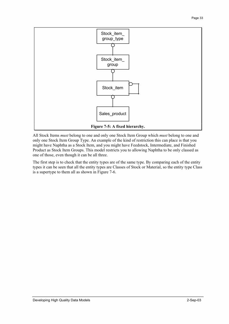
Figure 7-5: A fixed hierarchy.
All Stock Items must belong to one and only one Stock Item Group which must belong to one and only one Stock Item Group Type. An example of the kind of restriction this can place is that you might have Naphtha as a Stock Item, and you might have Feedstock, Intermediate, and Finished Product as Stock Item Groups. This model restricts you to allowing Naphtha to be only classed as one of those, even though it can be all three.
The first step is to check that the entity types are of the same type. By comparing each of the entity types it can be seen that all the entity types are Classes of Stock or Material, so the entity type Class is a supertype to them all as shown in Figure 7-6.
Developing High Quality Data Models 2-Sep-03
Page 34
Stock_item_group_type
Stock_item_group
Stock_item
Sales_product
Class
Stock_item_group_type
Stock_item_group
Stock_itemSales_product
Class
Stock_class
Are thesecardinalitiesalways true?
What do theserelationships
mean?1
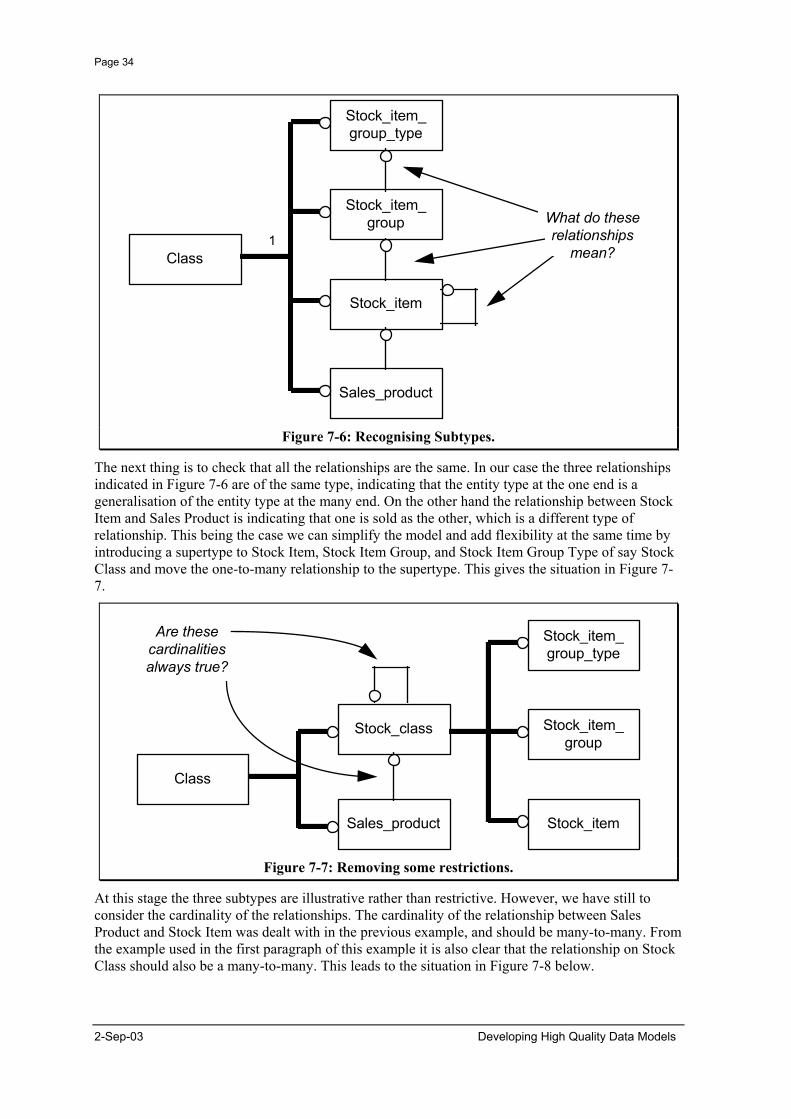
Figure 7-6: Recognising Subtypes.
The next thing is to check that all the relationships are the same. In our case the three relationships indicated in Figure 7-6 are of the same type, indicating that the entity type at the one end is a generalisation of the entity type at the many end. On the other hand the relationship between Stock Item and Sales Product is indicating that one is sold as the other, which is a different type of relationship. This being the case we can simplify the model and add flexibility at the same time by introducing a supertype to Stock Item, Stock Item Group, and Stock Item Group Type of say Stock Class and move the one-to-many relationship to the supertype. This gives the situation in Figure 7-7.
Figure 7-7: Removing some restrictions.
At this stage the three subtypes are illustrative rather than restrictive. However, we have still to consider the cardinality of the relationships. The cardinality of the relationship between Sales Product and Stock Item was dealt with in the previous example, and should be many-to-many. From the example used in the first paragraph of this example it is also clear that the relationship on Stock Class should also be a many-to-many. This leads to the situation in Figure 7-8 below.
2-Sep-03 Developing High Quality Data Models
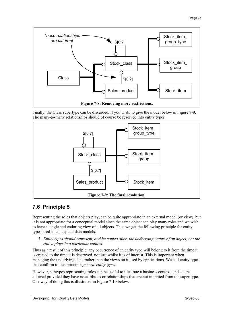
Page 35
Stock_item_group_type
Stock_item_group
Stock_itemSales_product
Class
Stock_item_group_type
Stock_item_group
Stock_itemSales_product
Stock_class
S[0:?]
S[0:?]
Stock_class
These relationshipsare different S[0:?]
S[0:?]
Figure 7-8: Removing more restrictions.
Finally, the Class supertype can be discarded, if you wish, to give the model below in Figure 7-9. The many-to-many relationships should of course be resolved into entity types.
Figure 7-9: The final resolution.
7.6 Principle 5
Representing the roles that objects play, can be quite appropriate in an external model (or view), but it is not appropriate for a conceptual model since the same object can play many roles and we wish to have a single and enduring view of all objects. Thus we get the following principle for entity types used in conceptual data models.
5. Entity types should represent, and be named after, the underlying nature of an object, not the role it plays in a particular context.
Thus as a result of this principle, any occurrence of an entity type will belong to it from the time it is created to the time it is destroyed, not just whilst it is of interest. This is important when managing the underlying data, rather than the views on it used by applications. We call entity types that conform to this principle generic entity types.
However, subtypes representing roles can be useful to illustrate a business context, and so are allowed provided they have no attributes or relationships that are not inherited from the super type. One way of doing this is illustrated in Figure 7-10 below.
Developing High Quality Data Models 2-Sep-03

Page 36
Sales Contract
ORGANISATION
CUSTOMER
SUPPLIER
AGENT Fleetof
Trucks
Sells Productsof Interest
to us
BuysOur
Products
SalesCatalogue
OperatesTransportService
Figure 7-10: Entity types should only represent the underlying nature.
The entity type representing the underlying nature is shown as a super type. The entity types representing the roles played are shown as subtypes. These entity types are given a number of names, overlapping subtypes, populations, or business views. We use the term population.
7.7 Context and Scope
Context
Scope
Figure 7-11: The scope must fit within the context for internal consistency
All data models have a context and scope, although they may not be formally defined. The context of a data model is the range within which it is valid, whilst the scope of a model is what it contains. This is illustrated in Figure 7-11 above. Note that the scope of a model is the same as or less than the context (otherwise the model will not be internally consistent). Thus a model might have a context of "sales", but a scope of only "order taking" in this case. It would be possible to expand the model to cover all of "sales" without changing what had already been modelled. A problem that often arises is that when there is a change in business requirements, the addition in scope to the model takes it outside the original context. This is illustrated in Figure 7-12 below.
2-Sep-03 Developing High Quality Data Models
Page 37
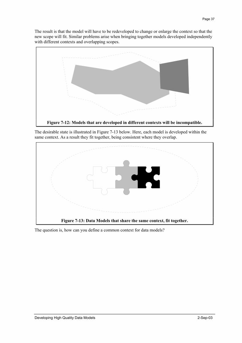
The result is that the model will have to be redeveloped to change or enlarge the context so that the new scope will fit. Similar problems arise when bringing together models developed independently with different contexts and overlapping scopes.
Figure 7-12: Models that are developed in different contexts will be incompatible.
The desirable state is illustrated in Figure 7-13 below. Here, each model is developed within the same context. As a result they fit together, being consistent where they overlap.
Figure 7-13: Data Models that share the same context, fit together.
The question is, how can you define a common context for data models?
Developing High Quality Data Models 2-Sep-03
Page 38
7.8 Principle 6
Not Useful Not UsefulUseful
ENTITY
CLASSIFIED
INDIVIDUALS
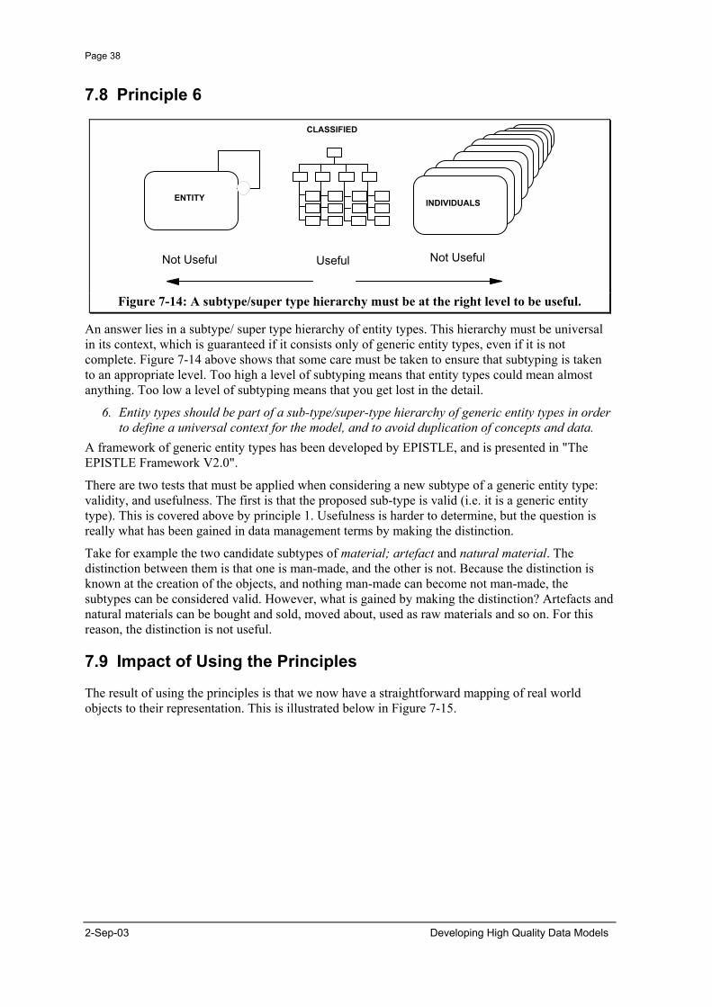
Figure 7-14: A subtype/super type hierarchy must be at the right level to be useful.
An answer lies in a subtype/ super type hierarchy of entity types. This hierarchy must be universal in its context, which is guaranteed if it consists only of generic entity types, even if it is not complete. Figure 7-14 above shows that some care must be taken to ensure that subtyping is taken to an appropriate level. Too high a level of subtyping means that entity types could mean almost anything. Too low a level of subtyping means that you get lost in the detail.
6. Entity types should be part of a sub-type/super-type hierarchy of generic entity types in order to define a universal context for the model, and to avoid duplication of concepts and data.
A framework of generic entity types has been developed by EPISTLE, and is presented in "The EPISTLE Framework V2.0".
There are two tests that must be applied when considering a new subtype of a generic entity type: validity, and usefulness. The first is that the proposed sub-type is valid (i.e. it is a generic entity type). This is covered above by principle 1. Usefulness is harder to determine, but the question is really what has been gained in data management terms by making the distinction.
Take for example the two candidate subtypes of material; artefact and natural material. The distinction between them is that one is man-made, and the other is not. Because the distinction is known at the creation of the objects, and nothing man-made can become not man-made, the subtypes can be considered valid. However, what is gained by making the distinction? Artefacts and natural materials can be bought and sold, moved about, used as raw materials and so on. For this reason, the distinction is not useful.
7.9 Impact of Using the Principles
The result of using the principles is that we now have a straightforward mapping of real world objects to their representation. This is illustrated below in Figure 7-15.
2-Sep-03 Developing High Quality Data Models

Page 39
Real World Object
Activities / Transactions/Associations / Event-Effects
Classes
Materials /Tokens
Roles/Involvements
Basic Data Types
Representation
Entity Types
Relationships
Attributes
Figure 7-15: Standardised representation of real world objects
The result of applying these principles is that models developed using them can be used for many purposes. This can be illustrated by the following example using a map in place of a data model.
York
London
CambridgeStratfordupon-Avon
Figure 7-16: Different uses can be made of the same model when it is neutral.
The map illustrated in Figure 7-16 shows some of the roads in the United Kingdom. However, it can be used for many purposes. For example, if you were travelling from London to York on business, you could look at the map and see that the quickest way was to go up the motorway.
However, you might also want to visit York for a holiday. It is a historic town with Roman walls and many beautiful buildings. In which case you might want to take in the sights on the way. You might decide to go via Cambridge, which is a beautiful university town, and perhaps via Stratford-upon-Avon, the birthplace of the famous playwright, Shakespeare.
Developing High Quality Data Models 2-Sep-03

Page 40
These different uses can be made of the map because it is neutral to the journey that is taken, or the purpose of the journey. A neutral data model can be used in the same way.
Increase Benefits
Reduce Costs
Minor changes minor rework
Common Systems
No system interfaces
Robust systems
Reuseable shareable
Data Models
Build from components
Consistent Data Models
Identify Potential reuse
Flexible Data Models
Data Modelling Standards
Figure 7-17: The objectives of Data Modelling Standards.
How this works for data models is illustrated in Figure 7-17. This shows that using the principles as a standard helps to develop data models that are:
• flexible, • consistent, • enable potential for reuse to be identified, • reduce the cost of maintenance, • make developing systems easier, • reduce the cost of system interfaces, and • make systems more robust, through using components that have already been tested through
use.
2-Sep-03 Developing High Quality Data Models

Page 41
8. Ah But ...
There are a number of questions that are frequently asked about the principles in the previous chapter. In this chapter we try to answer some of these questions.
8.1 But What About Performance?
When it comes to implementing systems based on conceptual models that follow the principles outlined here, the default database design can look rather different from a traditional database design. This gives the database a different performance profile, i.e. it does some things better, and some things worse. On balance there is a performance penalty; you don't get something for nothing.
There was a time when performance was an absolute issue. There were physical performance constraints from the hardware that you had to work within. For most cases this no longer applies. If you have a performance problem, you can solve it by throwing more hardware at it. If your application is processor bound, throw more processors at it (2, 10, 20 processors). If your application is I/O bound, strip the data over more disks. There is a cost to this, but then there are benefits too, and a normal business case can be made (or not) based on the lifetime cost of the system (not just project development and implementation costs).
Higher Maintenance Costs
Higher Enhancement Costs
Shorter System Life
Higher Hardware Costs
Higher Development Costs
Flexible DesignTraditional Design
(but reuse)
Figure 8-1: The Cost Balance for Flexible Design.
The balance of costs is shown in Figure 8-1. Traditional designs tend to optimise the initial development and implementation cost of a single system, at the expense of higher maintenance costs, higher enhancement costs, and in the end a shorter system life. On the other hand flexible designs require more powerful hardware to achieve the same performance, and have higher initial costs in development (although this will be offset because flexible components can be shared by or reused in several systems).
The relatively static cost of software development versus the plummeting cost of hardware means that the balance will become more and more one sided, in favour of flexible design.
Developing High Quality Data Models 2-Sep-03

Page 42
8.2 0.1. But How Do I Implement the Rules?
There is a school of data modelling which is almost completely at odds with the principles we have presented here. They would say that business rules should be enforced through the data model, and implemented in the structure of the data, e.g. an employee can have one and only one manager, implemented by having the manager as a column on the employee table. Only one manager can ever be held.
First, business rules are important. They do need to be held and enforced.
Second, only some business rules can be expressed in the data model, even if that is what you wish to do. There is a prize waiting for the person who can enforce the following rule in the structure of a single data model. "For a car to be allocated to an employee, the car must be owned by the department the employee works for".
The question then is not whether business rules should be expressed, but how. There are a number of good ways in which rules can be implemented in relational databases without affecting flexibility. They are using:
• indices to enforce uniqueness constraints, • views to maintain data in pre-defined combinations, • referential integrity constraints to maintain mandatory relationships, • stored procedures to enforce complex business rules on data storage and access, and • common modules to enforce business rules at the application level.
Thus insisting on the structure of your data being flexible places some restrictions on how business rules are expressed and enforced. It does not mean that they can't or shouldn't be held or enforced.
8.3 But I Want a Data Model I Can Show My Users
Data models that enable the sharing and exchange of data are not good for communicating a particular business perspective on the data, but this is often what people need to do, not least to ensure you have understood the requirement correctly!
Traditional entity-relationship diagrams have sometimes been found confusing by users. I was therefore very pleased to discover a set of diagramming conventions that leant themselves to being understood. These were defined by the developers of the CASE Data Interchange Format (CDIF) and have been adapted slightly here. An example model is given below in Figure 8-2.
The conventions are that the boxes are entity types and the arrows are relationships. The relationship is named in terms of the activity which causes the relationship between the entity types. The secret is that the direction of the arrow tells you how to read the relationship. Thus the first relationship is read as "Method contains Phase". People understand how arrows work. In fact you don't even need to tell your users it is an entity relationship model (why frighten them).
It is relatively straightforward to translate between this style of informal data model into a formal data model. Each relationship shown here maps to an entity type which represented the association or activity from the relationships.
2-Sep-03 Developing High Quality Data Models
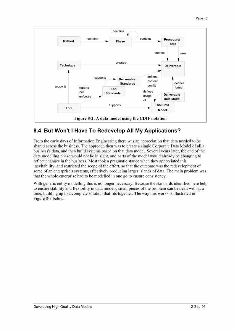
Page 43
Method Phase Procedure/ Step
DeliverableTechnique
Deliverable Standards
ToolTool Data
Model
Deliverable Data Model
Tool Standards
contains
contains
contains
creates
creates
defines format
defines content quality
supports
reports on/ enforces
supports
supports
defines usage of
uses
Figure 8-2: A data model using the CDIF notation
8.4 But Won't I Have To Redevelop All My Applications?
From the early days of Information Engineering there was an appreciation that data needed to be shared across the business. The approach then was to create a single Corporate Data Model of all a business's data, and then build systems based on that data model. Several years later, the end of the data modelling phase would not be in sight, and parts of the model would already be changing to reflect changes in the business. Most took a pragmatic stance when they appreciated this inevitability, and restricted the scope of the effort, so that the outcome was the redevelopment of some of an enterprise's systems, effectively producing larger islands of data. The main problem was that the whole enterprise had to be modelled in one go to ensure consistency.
With generic entity modelling this is no longer necessary. Because the standards identified here help to ensure stability and flexibility in data models, small pieces of the problem can be dealt with at a time, building up to a complete solution that fits together. The way this works is illustrated in Figure 8-3 below.
Developing High Quality Data Models 2-Sep-03

Page 44
Neutral File Format or Database
Interface Interface
ApplicationNew World Package
ApplicationTraditional
Figure 8-3: The practicalities of sharing and exchanging data between systems and
organisations.
Initially, a neutral data model might be developed as the basis for the exchange of data between systems using a flat file. This would have the advantage that only one interface would have to be built for each system, rather than one per system pair. Packages could be interfaced using this approach.
In the second phase the neutral data model might be implemented as a database to act as a buffer between existing systems. New systems could then use this database directly to share data, and extend it with their new requirements.
In addition, existing systems could be migrated to the neutral database as business requirements for concurrent access to data justified the cost.
8.5 But what about Object Orientation?
Here are two questions that get asked about object orientation.
• Is generic entity modelling object oriented? • Will generic entity modelling be made obsolete by object oriented methods?
Perhaps surprisingly, the answer to both is no. There is a great deal of hype about object orientation that suggests it is fundamentally different. This is not true, as becomes clear when you translate the object oriented words into Information Engineering terms. Take the Object Modelling Technique, proposed by Rumbaugh et al, which is generally regarded as the most complete of the current crop of methods. The basic methods employed are:
• data flow modelling, • state transition modelling, and • extended entity relationship modelling.
You may be familiar with all these. They are all well established techniques. The new bits are the extensions to entity-relationship modelling. These allow for multiple inheritance (multiple super-types) and methods in particular.
The hype suggests that these new features are a technology fix which will ensure that reusable components result from the development process. Unfortunately, this is not true. Whilst these new features do enable reusable components to be developed, it is not sufficient. It is better to think of
2-Sep-03 Developing High Quality Data Models
Page 45
the extensions as some more rope lying around the place with which you might hang yourself, particularly in the case of multiple inheritance.
More than ever, understanding the principles of how to develop good models will be important if the benefits promised by object orientation are to be delivered. Fortunately, the principles presented here apply as much to object oriented models as they do to entity relationship models. We expect to add to these principles over time as best practice in using the new features of object orientation emerges.
8.6 But Why Stop Here?
One of the questions we are sometimes asked is "why stop here?" Why not analyse further and make the models more generic?
The answer is that we have done. The next level of analysis takes the current relationships, which represent involvements, and represents them as entity types. This is followed by recognising that associations are derived entity types, and thus only hold data about the activities that cause and terminate associations. Finally, all attributes are represented as relationships to something else, except for the object identifier.
8.6.1 Really Generic! At about this point you reach a very pure form of theoretical data model known as a binary relational model. In a binary relational model no entity type has more than two attributes (including the many end of a relationship). Fortunately, it is not possible to analyse beyond this point. Unfortunately, the data model that results is almost impossible to understand.
8.6.2 Flexible and Stable The question is "why would you want a data model that generic?" The objective is to have models that are flexible and stable, not models that are generic. It happens that achieving models that are stable and flexible results in models that are more generic than is commonly the case today. Thus the standards presented here ensure that models are generic only where this contributes to stability and flexibility.
8.7 But Won't it Take Longer to Develop Data Models?
If you consider what happens currently, then what you see is that the same requirements are constantly being remodelled. Therefore, developing "better" data models does not necessarily mean it has to take longer because you can reuse existing models for part or all of your requirements. There is already enough work done for this almost always to be the case.
Developing High Quality Data Models 2-Sep-03
Page 46
9. Techniques for Creating Data Models
This section contains a collection of techniques we have come across or developed that have proved useful in creating and validating data models. They are offered here as a tool kit for you to use, rather than as a rigid method to be followed.
9.1 Source Material
9.1.1 Activity models, Interviews, and Forms The ideal situation for creating a data model is to have an accurate, written description of the business area to be modelled, and access to a group of people from the business who can be asked questions when clarification is required, and who can validate the model that is created.
At least some source material will come from interviews: the scope of the business area for instance. However, today it is relatively common to have a good written description of information requirements from activity models, and this should be at least one source for your analysis.
It is also worth mentioning that those who have not been involved with data modelling before often find it difficult to express themselves in data modelling terms. There are two approaches that can be taken. One is to teach them how to understand data models. The other is to model their requirements in a way they are familiar with, e.g. as an activity model, simplified data model, or as forms. The approach to take will depend on those involved. For users assigned to the project it is certainly worth ensuring they understand data models. For requirements gathering from the user community it is perhaps not necessary, and collecting the general data requirements in their terms may be more appropriate.
9.1.2 Existing Systems One of the more common problems when developing data models for new systems is that whilst they represent what the old system didn't do well, they sometimes don't cover what the old system did do well, because everyone took it for granted, and forgot to mention it as a requirement. It is therefore important to check through the old system(s) (be they manual or automated) to ensure you model all the things that need to be modelled. Discarding functionality and data should be a conscious decision.
9.2 Workshops
One of the most powerful ways to get a data model that stakeholders are committed to is to involve them in its creation. Creating the model in a workshop is an effective way of doing this. It brings stakeholders together, ensuring that they see other stakeholders' perspective on what is being modelled, and enables conflicts to be more readily identified and resolved.
A workshop session should involve between 4 and 6 people to be effective. One member of the team should be expert in the modelling techniques and act as facilitator. For large modelling exercises, modelling sessions can be held in parallel with the results fed back to the whole group in plenary.
9.2.1 Mapping to the Generic Entity Framework Ideally you will be starting from an agreed text describing the area to be modelled, often an activity model. The approach to take is to identify (underline) the key words (nouns and verbs) in the description.
2-Sep-03 Developing High Quality Data Models

Page 47
The next task is to map these words to the Generic Entity Framework. Often it will be necessary to ask additional questions to clarify what is meant in order to be able to place the word in the framework. This is an important part of the analysis process. The following are the minimum set of questions that should be asked.
• Is this a particular thing, or a type of thing (differentiates between instance and class)? • What Subject (activity, association, material, etc.) does it fall under? • What Qualifier (actual, planned, etc.) does it fall under?
Often you will find that the same word falls in more than one place. This is quite normal and can be for a number of reasons.
• The word represents a complex concept. • The word is a homonym (has more than one meaning). • The discussion brings related concepts to light.
When this happens all the mappings should be considered valid, at least initially. Additional mappings should be created and added in the relevant place, perhaps with a qualifying word or number to differentiate them.
Using these templates small pieces of model (fragments) can be developed and put together to realise models that are both large and consistent.
9.2.2 Selecting and Using Templates Applying the principles identified here makes it relatively easy to develop data models by starting from the key activities and associations, and then identify what other things are involved in them. This is one reason why activity models make such a good source of material for developing a data model.
Starting with the activity or association, look through the templates in the "EPISTLE Framework" to see if any of them applies. Remember that many business activities can be decomposed into simpler activities.
If a template can be found, then the next step is to identify what plays the various roles identified in the template for your situation.
If you cannot find an existing template, then you need to create one by identifying the different things that are involved in the activity or association.
9.2.3 Use of Populations to Illustrate Usage The formal entity types in the model are the generic entity types from the framework, because they will be the basis for consistency and sharing across models. However, it is desirable to make the current usage of these entity types clearer. This can be done by adding populations to the data model.
Populations are illustrative sub-types of the generic entity types. They illustrate a particular context, and are allowed to overlap with each other. For example, whilst customer and supplier do not pass the test as generic entity types, they are quite acceptable as populations.
The key rule about populations is that they do not have relationships or attributes, except those which they inherit from the generic entity type they belong to.
9.2.4 Using Examples To Check The Model Once the model fragment around an activity or association has been created, check it out with example data. This helps to ensure the model does what you think, and also helps to clarify what the model represents.
Developing High Quality Data Models 2-Sep-03

Page 48
9.2.5 Resolving Conflicts Conflicts are common when developing data models. Hard debate is one of the best ways to discover the truth. However, it is important to remember that it is the merits of ideas that are being debated, not the merits of people. One of the most important things to realise for a facilitator, is that in cases of conflict the challenge is to find out how it is both sides are right.
Arguments are most often over words and what they mean. It is important to understand that for the model it is the meaning rather than the word that represents it that is important. One way to separate the word from the meaning is given below.
"Call it a duck" is the battle cry, and then get each of the protagonists to describe what their "duck" is. Usually, you will discover that two different things are being discussed, described by the same word (homonym). Afterwards names can be chosen to distinguish the two different concepts.
Another common problem is that people want different names for the same thing (synonyms). That's OK. You don't have to choose. Just concatenate them. Then everyone is happy. Eventually, a natural selection process takes place, and one of the names, or a new one emerges. We once had an entity type called characteristic/ property/ specification!
When the discussion is about relationships, you may find people trying to enforce business rules through the cardinality. "But we never have more than one manager for an employee". Point out that it isn't necessarily always true for everyone. Try to think of when it is not the case, "We might want to keep the history of whom an employee has been managed by" might work in this case. Point out that the model does not prevent them from having only one manager per employee. It just doesn't enforce it for others. Capture the rule in some other way, e.g. in the definition of the employee population.
Sometimes users or system developers will not like the model you produce because it doesn't reflect how they see things. Remember, it isn't supposed to reflect a particular view point, so this may happen quite often. However, the model is supposed to meet the data requirement, so you should ask the objector to identify data that the model does not hold (remember data, not rules). Examples should be required to justify any complaint. If you cannot demonstrate how the example data can be held, you need to extend your model, (this is the only sound basis for objection).
Sometimes an issue may have been discussed, and you have gone round in circles a couple of times without reaching a resolution. The most likely reason for this is that you are missing the information needed to resolve the issue. Log the issue and move on. Something usually turns up later to resolve it that is unknown or unclear now.
9.3 Documenting Data Models for Others
Data models are often documented in a way that is unclear or ambiguous, so that readers will have a number of questions about the intention of the model. This is not to say that the originator of the model did not know what the model was supposed to represent, but that it had not been communicated. Too often data model documentation is only useful to the author(s) of the data model. This is a severe curb on obtaining useful comment on the model, or in getting it used by others.
9.3.1 Subject Areas - Size and Layout The first point is that entity relationship diagrams should be kept small. Preferably not more than 10 or so entity types. This means that most data models will have to be split up into a number of diagrams or subject areas.
The reason for limiting the size of a subject area is so that the data model can be seen and understood with a particular focus. A single diagram with perhaps several hundred entity types
2-Sep-03 Developing High Quality Data Models

Page 49
leaves you wondering where to start, and what is relevant in your circumstances. Using subject areas shows you what is relevant for your situation, and gives you a place to start.
You will notice that the data model diagrams in this document have a distinctive style which we recommend because it both helps to lay out and read the diagrams. Relationships are horizontal, and thus so are the relationship names. You can then read the diagram from left to right, rather than round corners.
9.3.2 Subject Area Descriptions Accompanying the diagram there should be a description of the diagram in plain language. The objective should be both to explain what the diagram means to those who cannot read the model, and to provide a cross check for those who are reviewing the model of what it is supposed to represent. It is useful to document key concepts, how you have modelled these, and any unresolved issues here too, since these will help others to understand what you have done.
9.3.3 Examples Adding examples to the subject area diagram is a great aid to explaining what a model means. The examples of each entity type should be from one or more consistent examples, and the example should be talked through in the subject area description.
9.3.4 Entity Type Definitions Unfortunately, entity type definitions are often ambiguous or unclear. We recommend the following general structure for a definition:
A (reference to supertype) that (distinguishing features).
For example, the definition for process plant might read:
A facility that is used to transform feedstocks into products.
Referring to a generic entity type clearly identifies the type of thing that is being referred to, whilst the distinguishing features will tell what makes these different from others of the same generic entity type.
For association entity types the form of the definition should be:
An association that indicates an (entity type name from one relationship) is (nature of association) for an (entity type name from other relationship).
For example, the definition for the entity type storage (of material) might read:
An association that indicates a material is stored in a facility.
Notice that the formal definition is clear, concise, and unambiguous (i.e. you could look at something and say whether or not it belonged to the entity type). Definitions with words like 'and', 'or', or 'where' in them should be viewed with suspicion.
As well as the formal definition, additional notes may be added as to the interest in the entity type and how it may be used. Special restrictions and business rules may also be added here.
Finally, examples should be included to confirm the meaning.
9.3.5 Entity Type to Subject Area Cross Reference It is important to understand the usage of different entity types. You should therefore create an entity type to subject area cross reference that shows the subject areas an entity type appears in (the cross reference the other way is best found by looking at the subject area diagrams). This can be generated from most CASE tools, and can be conveniently documented with the entity type definition.
Developing High Quality Data Models 2-Sep-03

Page 50
9.3.6 Estimating Guidelines for Documentation Documenting data models (as opposed to developing them) to this standard does not come free. Our experience is that it takes about one man month to document 100 entity types to the standards identified here.
2-Sep-03 Developing High Quality Data Models

Page 51
10. EXPRESS-G Notation
Entity type Base type
Defined type
STRINGINTEGERREALBOOLEAN
Enumeration type
Select type
mandatory attribute or relationship
optional attribute or relationship
subtype
Figure 10-1: Data Model notation.
Entity type Base type
Entity type Entity type
attribute name
relationship name
An attribute specifies the role played by a base type (or anenumeration, select, or defined type) in the definition of an entitytype.A relationship specifies the role played by an entity type in thedefinition of another entity type.
or anyother type
Figure 10-2: Attributes and relationships.
Developing High Quality Data Models 2-Sep-03

Page 52
EXPRESS-G specifies the cardinality of an attribute relationshipin terms of an aggregation (SET, BAG, ARRAY, LIST).In this course we are mainly interested in cardinalities, so weassume that all aggregates are SETs.
A B
A B
role
role S[1:?]
exactly one B for each A
one or many B for each A
Figure 10-3: Cardinalities.
Every relationship has an inverse.Default is that the inverse relationship is not named, and that thecardinality is zero, one or many.Naming the inverse allows this to be constrained.
A Brole
exactly one B for each A
default inverse:zero, one or many Afor each B
Figure 10-4: Inverse Relationships.
The boxes represent entity types and the lines between them relationships. Figure 10-2 to Figure 10-4 above show the meaning of the symbols used for relationships. The relationship between two entity types can be read in either direction as indicated in Figure 10-5 and Figure 10-6 below.
2-Sep-03 Developing High Quality Data Models

Page 53
Batch Product_typeclassed_as
Read in the direction of the “lolly-pop”.Batch - classed as - Product type.
Figure 10-5: Reading the relationship from Batch to Product Type.
Read the inverse in the opposite direction.Product_type - classifies - Batch.
Batch Product_typeclassed_as
(INV) classifies S[0:?]
Figure 10-6: Reading the relationship from Product Type to Batch.
This is often as much as required for business use, however, the diagrams do say more about the number of entities (instances) at one end of a relationship that may or must be involved with an instance at the other end. This is referred to as the cardinality of a relationship. The meaning is explained in Figure 10-7 and Figure 10-8.
Developing High Quality Data Models 2-Sep-03
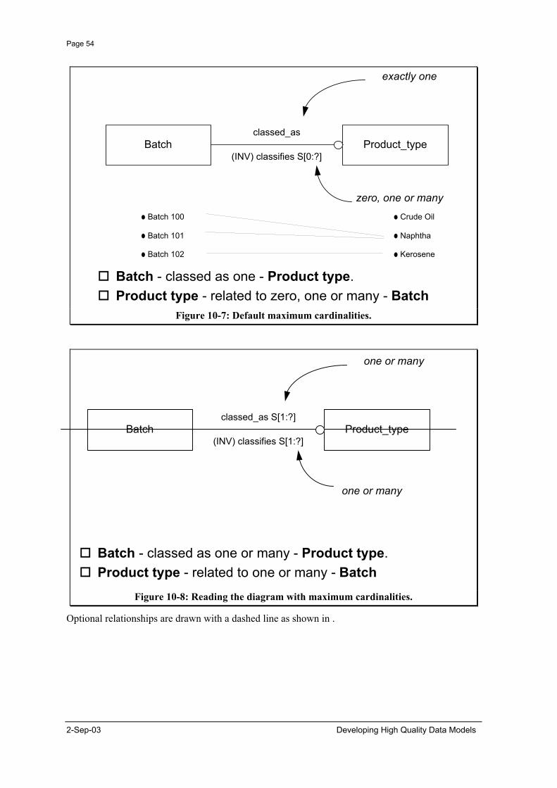
Page 54
Batch - classed as one - Product type.Product type - related to zero, one or many - Batch
Batch Product_typeclassed_as
exactly one
(INV) classifies S[0:?]
zero, one or manyBatch 100
Batch 101
Batch 102
Crude Oil
Naphtha
Kerosene
Figure 10-7: Default maximum cardinalities.
Batch - classed as one or many - Product type.Product type - related to one or many - Batch
Batch Product_typeclassed_as S[1:?]
one or many
(INV) classifies S[1:?]
one or many
Figure 10-8: Reading the diagram with maximum cardinalities.
Optional relationships are drawn with a dashed line as shown in .
2-Sep-03 Developing High Quality Data Models
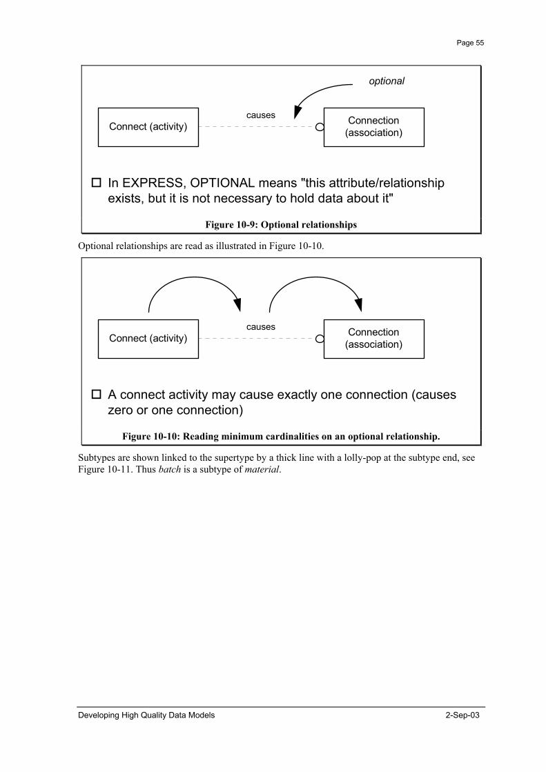
Page 55
In EXPRESS, OPTIONAL means "this attribute/relationshipexists, but it is not necessary to hold data about it"
Connect (activity) Connection(association)
causes
optional
Figure 10-9: Optional relationships
Optional relationships are read as illustrated in Figure 10-10.
A connect activity may cause exactly one connection (causeszero or one connection)
Connect (activity) Connection(association)
causes
Figure 10-10: Reading minimum cardinalities on an optional relationship.
Subtypes are shown linked to the supertype by a thick line with a lolly-pop at the subtype end, see Figure 10-11. Thus batch is a subtype of material.
Developing High Quality Data Models 2-Sep-03
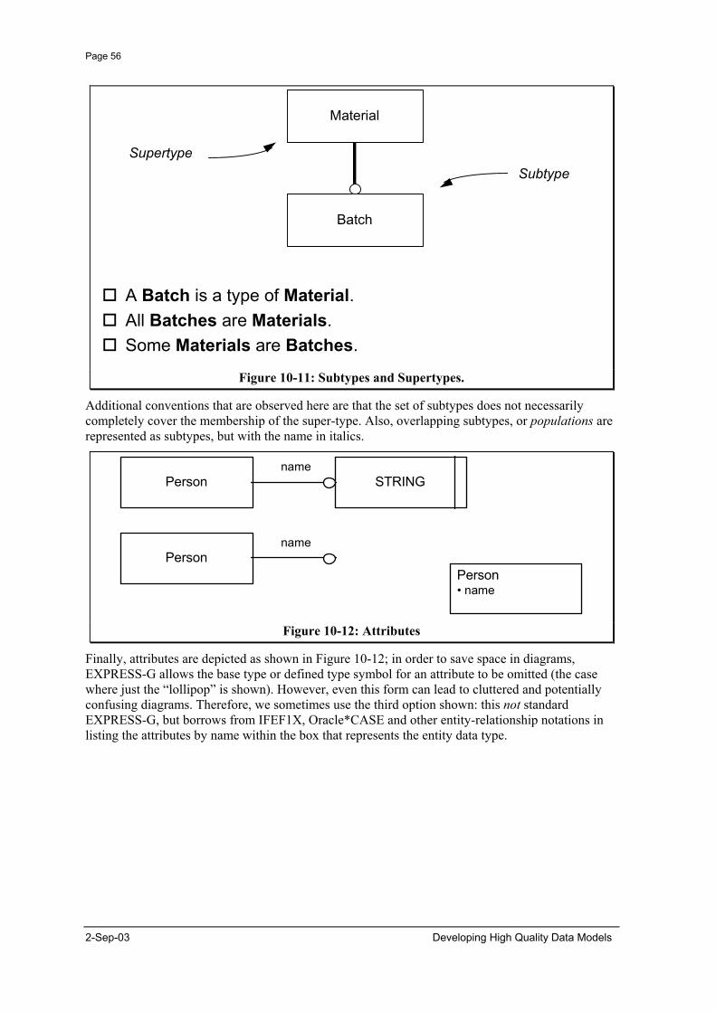
Page 56
2-Sep-03 Developing High Quality Data Models
A Batch is a type of Material.All Batches are Materials.Some Materials are Batches.
Batch
Material
SupertypeSubtype
Figure 10-11: Subtypes and Supertypes.
Additional conventions that are observed here are that the set of subtypes does not necessarily completely cover the membership of the super-type. Also, overlapping subtypes, or populations are represented as subtypes, but with the name in italics.
Person STRINGname
Personname
Person• name
Figure 10-12: Attributes
Finally, attributes are depicted as shown in Figure 10-12; in order to save space in diagrams, EXPRESS-G allows the base type or defined type symbol for an attribute to be omitted (the case where just the “lollipop” is shown). However, even this form can lead to cluttered and potentially confusing diagrams. Therefore, we sometimes use the third option shown: this not standard EXPRESS-G, but borrows from IFEF1X, Oracle*CASE and other entity-relationship notations in listing the attributes by name within the box that represents the entity data type.