Embed Size (px)
Citation preview
Development and Implementation of an
Automated Measurement System for RF
Parameters of a DECT System
Bachelor Thesis Presentation
Alireza Ghaffari
University of Duisburg-Essen
Prof. Dr. -Ing. Klaus Solbach
Lantiq Deutschland GmbH
Outline
• Task Description
• Introduction to DECT
• Remote Controlling Measurement
Equipment
• Automation of DECT Measurements
• Conclusion
2
Task Description
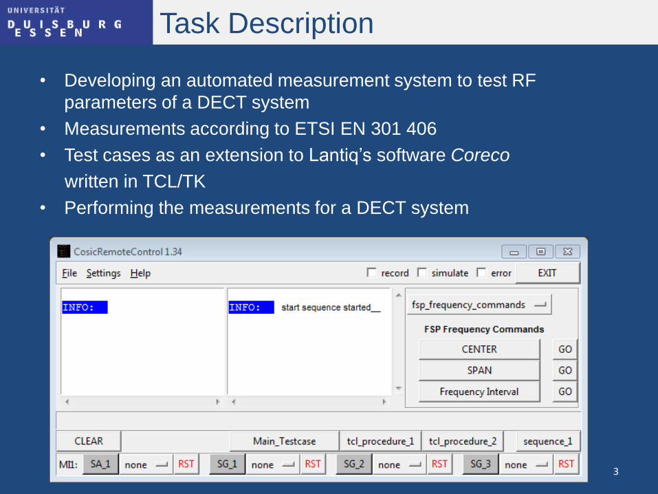
• Developing an automated measurement system to test RF
parameters of a DECT system
• Measurements according to ETSI EN 301 406
• Test cases as an extension to Lantiq’s software Coreco
written in TCL/TK
• Performing the measurements for a DECT system
3
Introduction
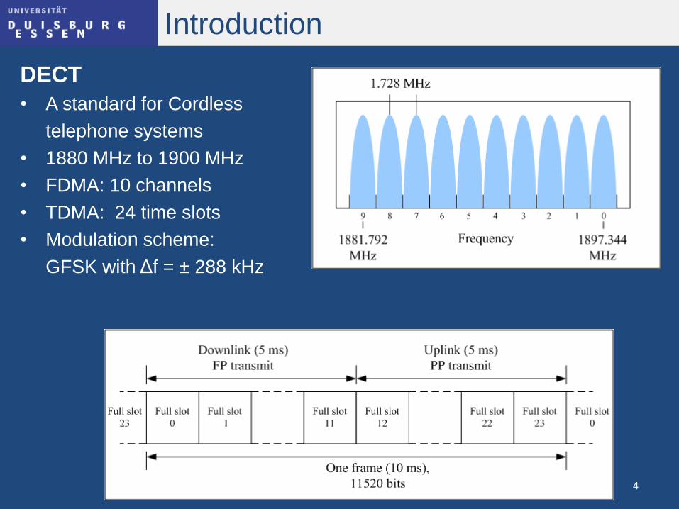
DECT
• A standard for Cordless
telephone systems
• 1880 MHz to 1900 MHz
• FDMA: 10 channels
• TDMA: 24 time slots
• Modulation scheme:
GFSK with Δf = ± 288 kHz
4
Introduction
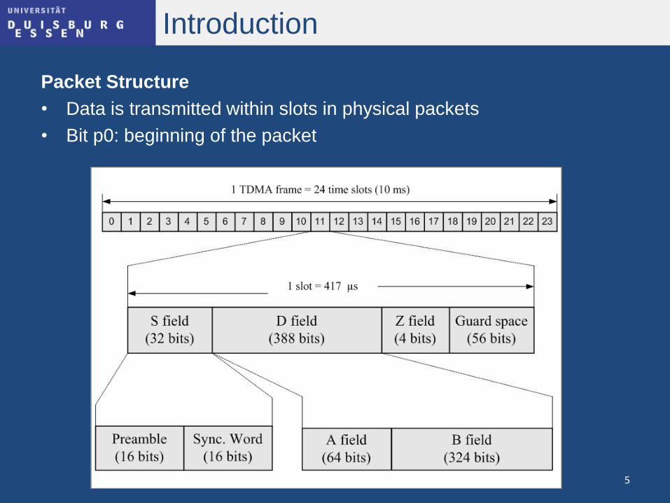
Packet Structure
• Data is transmitted within slots in physical packets
• Bit p0: beginning of the packet
5
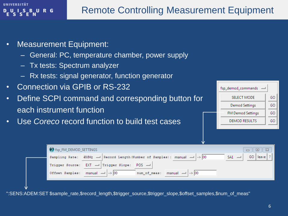
Remote Controlling Measurement Equipment
• Measurement Equipment:
– General: PC, temperature chamber, power supply
– Tx tests: Spectrum analyzer
– Rx tests: signal generator, function generator
• Connection via GPIB or RS-232
• Define SCPI command and corresponding button for
each instrument function
• Use Coreco record function to build test cases
":SENS:ADEM:SET $sample_rate,$record_length,$trigger_source,$trigger_slope,$offset_samples,$num_of_meas"
6
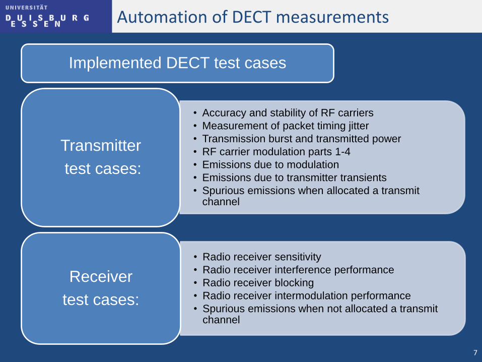
Automation of DECT measurements
Implemented DECT test cases
• Accuracy and stability of RF carriers
• Measurement of packet timing jitter
• Transmission burst and transmitted power
• RF carrier modulation parts 1-4
• Emissions due to modulation
• Emissions due to transmitter transients
• Spurious emissions when allocated a transmit channel
Transmitter
test cases:
• Radio receiver sensitivity
• Radio receiver interference performance
• Radio receiver blocking
• Radio receiver intermodulation performance
• Spurious emissions when not allocated a transmit channel
Receiver
test cases:
7
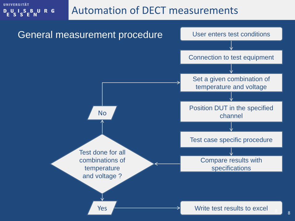
Automation of DECT measurements
General measurement procedure User enters test conditions
Connection to test equipment
Set a given combination of
temperature and voltage
Position DUT in the specified
channel
Test case specific procedure
Compare results with
specifications
Test done for all
combinations of
temperature
and voltage ?
No
Yes Write test results to excel 8 8
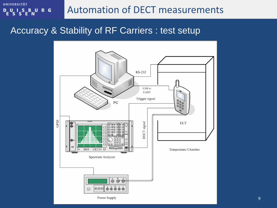
Automation of DECT measurements
Accuracy & Stability of RF Carriers : test setup
9
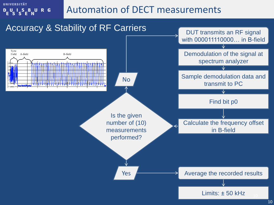
Automation of DECT measurements
Accuracy & Stability of RF Carriers DUT transmits an RF signal
with 000011110000… in B-field
Demodulation of the signal at
spectrum analyzer
Sample demodulation data and
transmit to PC
Find bit p0
Calculate the frequency offset
in B-field
Is the given
number of (10)
measurements
performed?
No
Yes Average the recorded results
Limits: ± 50 kHz
10
10
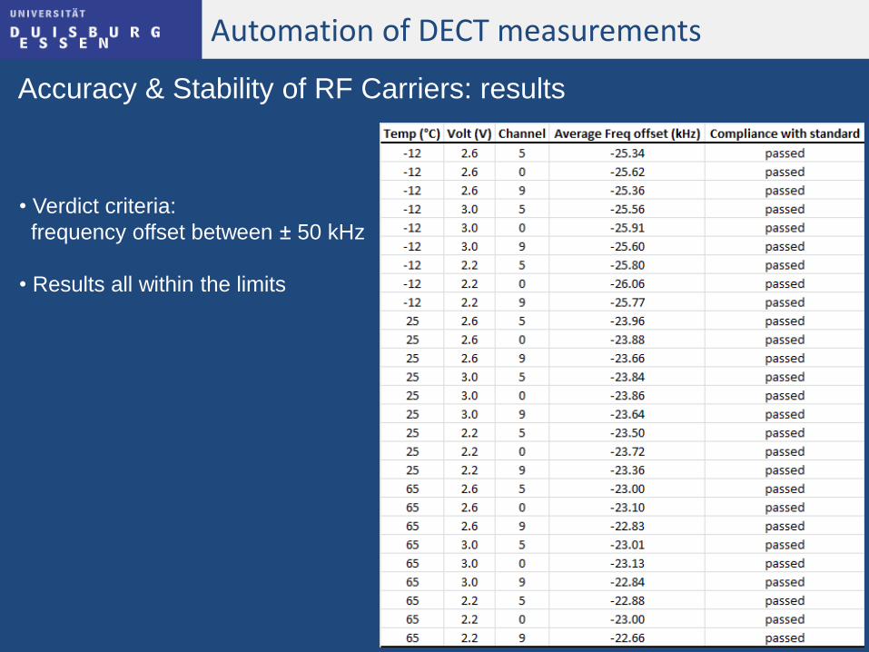
Automation of DECT measurements
Accuracy & Stability of RF Carriers: results
• Verdict criteria:
frequency offset between ± 50 kHz
• Results all within the limits
11
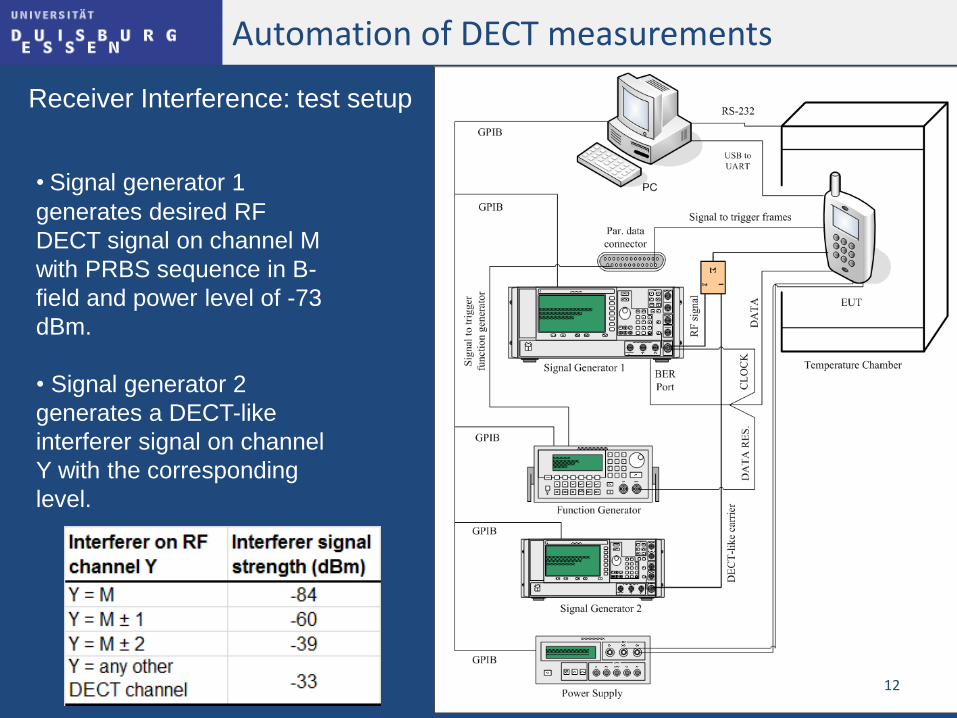
Automation of DECT measurements
Receiver Interference: test setup
• Signal generator 1
generates desired RF
DECT signal on channel M
with PRBS sequence in B-
field and power level of -73
dBm.
• Signal generator 2
generates a DECT-like
interferer signal on channel
Y with the corresponding
level.
12
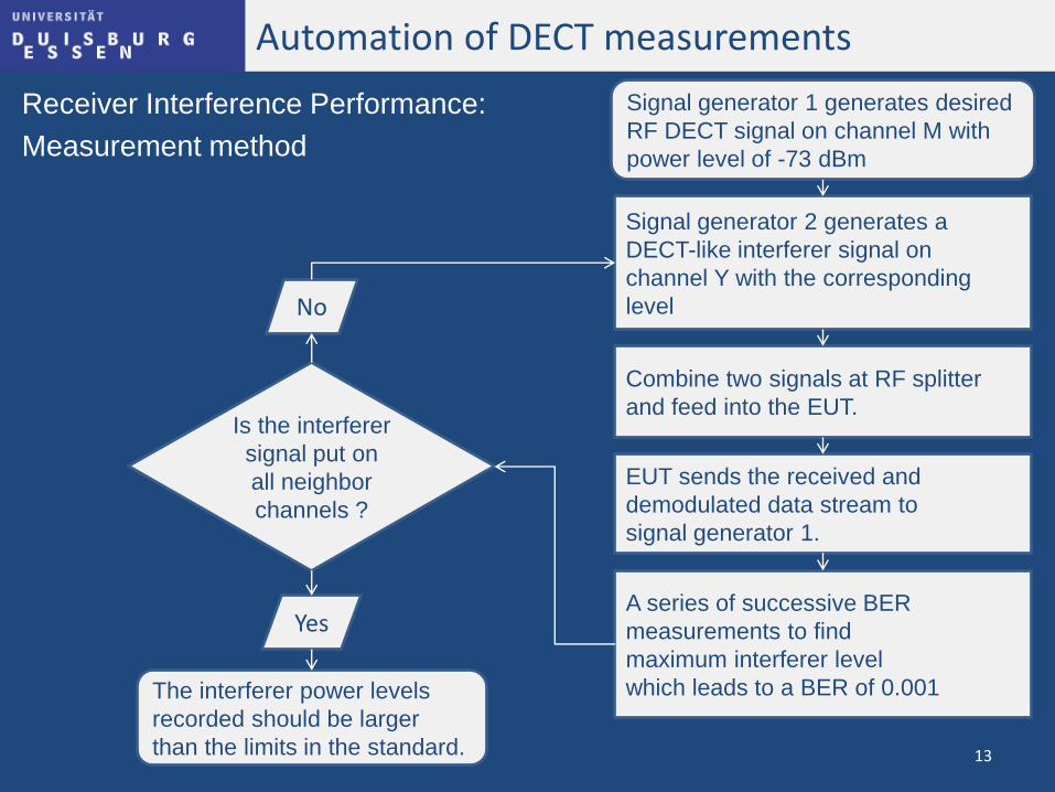
Automation of DECT measurements
Receiver Interference Performance:
Measurement method
Signal generator 1 generates desired
RF DECT signal on channel M with
power level of -73 dBm
Is the interferer
signal put on
all neighbor
channels ?
No
Yes
The interferer power levels
recorded should be larger
than the limits in the standard.
Signal generator 2 generates a
DECT-like interferer signal on
channel Y with the corresponding
level
Combine two signals at RF splitter
and feed into the EUT.
EUT sends the received and
demodulated data stream to
signal generator 1.
A series of successive BER
measurements to find
maximum interferer level
which leads to a BER of 0.001
13
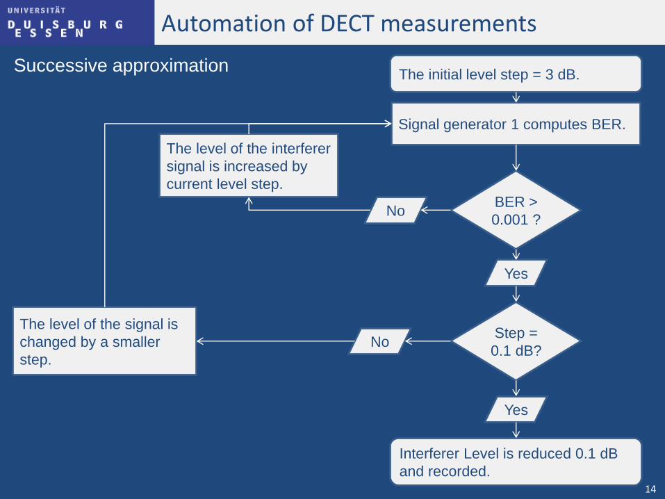
Automation of DECT measurements
Successive approximation The initial level step = 3 dB.
Interferer Level is reduced 0.1 dB
and recorded.
Signal generator 1 computes BER.
BER >
0.001 ?
Yes
Step =
0.1 dB?
No
No
The level of the interferer
signal is increased by
current level step.
The level of the signal is
changed by a smaller
step.
Yes
14
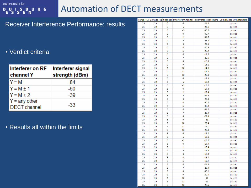
Automation of DECT measurements
Receiver Interference Performance: results
• Verdict criteria:
• Results all within the limits
15
Conclusion
Advantages of the developed automated system
• Flexibility: extend it to be used for WDCT
• Ease of use
• Documentation
Drawbacks
• Timing: time to transfer data to PC
16