Embed Size (px)
Citation preview

SI N ava It I
DevelopmentWý Center
Johnsville, Pennsylvania
-C44-6622 10 meI*r It"
A Qu•antitative Impedance Pneumoseaph
Naval Air System ComandWeptauk R360 FT 102/2021/101 101 01
(r-5 -01)
DISTRIUTION OF THIS DOCUMMNT IS UNLINITID
L CLEAR INGH OUSE-FOR FF.DERAL SCIENTIFIC AND
ftCH"NICAL INFORMATION
Lmitations concerRing the distribution ofthis report and revelation of its contents
appear on the Inside of this cover.

DEPARTMENT OF THE NAVYU. S. NAVAL AIR DEVF[O'PMFNT CENTER
JOHNSVILLE
WARMINSTFR. PA. 18974
Aerospace Medical Reaearch Department
NADC-MR-6622 10 November 1966
A Quantitative Impedance Pneumograph
Naval Air Systems CommandWeptask R360 FR 102/2021/R01 101 01
(RF-5-01)
DISTRIBUTION OF THIS DOC T IS UNLI D
Prepared by: 7 e E. Bergey
Willi C..Si. l
William C. Sile
Wilviim" A. hamilton
Russell D. Squ
Approved by: C. F. Schmidt, M.D.Research DirectorAerospace Medical Research Department
ReLeased by: E. M. Wurxel,('APT, MC, USNDirector,A-rospace Medical Research Department

SUMMARY
quantitatively respiratory volumes. Features of this system include the useof a higher frequency (300 KHz) excitation voltage than 1q norm.llvy used Inimpedance pneumography and the use of pasteless electrodes which are insulatedfrom the subject by a layer of polyethylene, thus forming a capacitive couplingof the electrodes to the subject and elimnnating the problems associated withakin-to-electrode impedance changes. A near perfect empiric correlation wasfound to exist between the transthoracic impedance measured by this device andpulmonary volume,
it

TABLE OF CONTENTS
Page
SUMMARY - i-
INTRODUCTION 1 -
CIRCUIT DESCRIPTION --- - ----------------- I
ELECTRODES ..............-.........---------------- 4
VESTS . . . . . .- . . . . . . . . . . . . ..-. . . . ..------------- 7
CALIBRATION PROCEDURE ....-.......---.-.-.- - --------- 9
RESULTS OF IMPEDANCE PNEUMDGRAPH EXPERIMENTATION - 15
POSITION AND WEIGHT OF SUBJECT -- ---------------- 15
BASELINE SHIFTS DUE TO LEG RAISING, MUELLER ANDVALSALVA MANEUVER -- --------------------------- 15
EFFECTS OF DIELECTRIC --- ----------------------- 20
DISCUSSION -- --------------------------------------- 20
REFERENCES -- --------------------------------------- 22
BIBLIOGRAPHY -- ------------------------------------- 23
LIST OF FIGURES
Figure Title Page
1 Impedance pneumograph (Schematic) ------------- 2
2 Impedance pneumograph (Physical construction) 3
3 Attenuation of output as a function of oscillatorfrequency -.-.-.------- ----------------------- .5
4 Respiratory volume versus time as recordedsimultaneously by the standard 3pirometer (bottom"trace) and an impedance pneumogeaph -.--------
5 Respiratory volume versus time as. recordedsimultaneously by the impedance pneumograph (trace A)and the standard spirometer (trace B) ..... 6
iii

LIST OF FIGURES
Single electrode for pneumoRraph before enclosurein polyethylene bag -.-.-.----- - - ---------------- 8
7 "Tailor-fitted" vest showing electrodes on either
side -- --------------------------------------- 10
8 Subject in vest showing telemetry packages ... 11
9 Universal vest with telemetry packages in pockets - 12
10 Subject in universal vest -- -------------------- 13
11 Reduction of pneumograph output at high respiratoryrates - ------------------------------------ 14
12 Calibration curve for the spirometer to be used asthe primary standard -- ------------------------ 16
13 Calibration curve for the impedance pneumographshown in figure 1 -- ------------------------- 17
14 Impedance change caused by raising the legs of asubject lying on his back -- ----------- 18
15 Impedance changes caused by the subject performinga Mueller maneuver (interval A to B) and a Valsalvamaneuver (interval C to D) -- ------------------ 19
16 "Clipping" of the pneumograph output (trace A) athigh inspiratory and expiratory levels caused bythe interposition of three layers of surgical gauzebetween the insulated electrodes and the subject'schest - ---------------------------------------- 21
iv

INTRODUCTION
h Uy a numaber or investigators toquantitatively correlate transthoracic impedance variations with respiratoryvolume changes. The advantaaes of the impodAnne tehn~q,- are o ---•htu..: norestraint is placed on the subject; the entire system is small and light inweight and it can be worn for relatively long periods of time and used for avariety of applications. The technique described in this report has the followingadvantages over other impedance pneumography systems. The frequency of thealternating current applied to a pair nf electrodes is considerably higher (300KHz)than that used by most experimenters (1, 2, 3). More importantly, the twoelectrodes are insulated from the subjectra skin which results in a much moreaccurate indication of pulmonary volumes than the semiquantitative resultsdescribed in previous reports. Variations in the impedance between skin andelectrode, which bear little relevance to pulmonary variations, are eliminatedby capacitively coupling the electrodes to the subject and thus the pneumographmeasures only the impedance of the substance between the two electrodes. Anear-perfect empiric correlation was found to exist between this transthoracicimpedance and respiratory volumes.
This impedance pneumograph was designed to be compatible with a telemetrysystem capable of measuring other physiological parameters such as electro-cardiogram (EKG), electroencephalogram (EEG), temperature, and blood pressure.The electrodes developed for both EKG and respiration were pasteless and thereforeeasily applicable, non-irritating, and capable of being worn for extended periodsof time. Geddes, et al. (4) has described systems which use common electrodesfor monitoring EKG and respiration. Since insulated electrodes could not be usedfor the relatively low irequency voltages of EKG, the telemetry system describedherein utilizes separate electrodes for measuring respiration and EKG. It wasfelt that this method would not detract from the advantages of the system sincethe separate electrodes can be placed on the subject as a unit with the smallerEKG electrodp placed in contact with the subject's chest.
CIRCUIT DESCRIPTION
Basically, the impedance pneumograph (Figures 1, 2) consists of a singletransistor oscillator purposely designed "soft" so that a relatively small changein the load impedance will cause the amplitude of the output to vary considerably.The varying load impedance is comprised oi the impedance between the two electrodesand varies with respiration. At the frequency used (300 KUz), the load impedanceusing the electrodes described is approximately 35 ohms. Respiration causes the
impedance to vary slightly less than 1.0 ohm per liter. The varying amplitude300 Kliz signal is then demodulated using a half wave rectifier-filter, thus pro-ducing a direct current whose voltage is proportional to the oscillator's load.This DC output then can be used to drive a high impedance recorder directly orto drive a voltage-controlled sub-carrier oscillator for use in an FM-FM telemetrysystem. Telemetering the signal appears to be the most advantageous method in

*•1-- 4.0V
200uHIM .0047 FDIOO
01 .002 .1 e35VNS7070
33K ,M .18 35V2.7K T'01 q
C= CLE lectrodes
Figure 1. Schematic of imnedance nneumograoh. A modified Colpitta oscillatorapplies a 300 Kilohertz voltage to the body through a pair of insulatedelectrodes with variations in the impedance between electrodes causingamplitude modulation of the oscillator's carrier. These amplitude variationsare extracted from the carrier by the diode and subsequent filter resultingin a DC signal whose voltage was empirically found to be proportional topulmonary volumes. This varying voltage can be used to drive a subcarrieroscillator in an FM-FM telemetry system.
2

I -L I -I - I I I I -- - 10 2 3 4 5METIRIC
Figure 2. Use of a microtransistor and miniaturized components enable compactconstruction of the impedance pneumograph for applications where space iscritical. This particular unit, after encapsulation in epoxy, measured3/8 x 5/8 x 7/8 inches end was incorporated along with a number of othermodules in a miniature biotelemetry system.
3

that artifact due to changes in the subject's position relative to ground areminimized. If the signal is coupled to a recorder directly, movement artifactS........ .h... =c c ! iia.16oiu u L•iic -Ioor, or when rhe subject cnanges nisproximity to grounded equipment.
Considerable experimentation was done concerning the optimum frequencyat which to operate the pneumograph oscillator. Previous attempts at impedancepneumography utilized frequencies in the 25 to 100 KHz range. It was felt thatthe use of a higher frequency would be advantageous in several respects. First,a higher carrier frequency requires less filtering to demodulate. Second, ifother parameters such as EKG or EEG are being monitored simultineously withrespiration, a higher frequency will be more easily filtered out of the inputsto the other amplifiers, thus eliminating interference from the pneumographoscillator. Third, in spite of the findings of previous investigators (5), thesensitivity of the pneumograph increased as the oscillator frequency was in-creased to about 360 KHz (Figure 3). Higher frequencies were tried with littlesuccess, possibly because of skin effect or some other phenomenon which alteredthe pathway of the RF radiated between the electrodes.
By comparing Figure 4 with Figure 5, it can be seen that not only doesthe sensitivity of the pneumograph decrease at lower frequencies, but also theaccuracy of the output as an indicator of respiratory volumes is poorer.
The circuit shown in Figure I produces a 4 volt peak-to-peak sinusoidalpotential between the two insulated electrodes. The voltage required for accurateresults from the pneumograph varies with the physical habitus of the subject, sizeof the electrodes, and frequency of the oscillator. In order to minimize inter-ference with the simultaneous measurement of other physiological parameters, thevoltage applied to the electrodes should be kept as low as is necessary toobtain accurate results. With the system described in this report, the optimumvoltage, with respect to accuracy and interference, was found to be the 4 voltspeak-to-peak mentioned above. With the electrodes in place on the subject, thetransthoracic impedance loads the oscillator and the voltage is reduced to approx-imately 3 volts peak-to peak depending on the physical habitus of the subject.
Voltages lower than 4 volts peak-to-peak proved unreliable on all butthe thinner subjects. Increasing the voltage beyond 4 volts peak-to-peak did notsignificantly improve the accuracy of the output and beyond 18 volts peak-to-peakaccuracy declined, and, of course, interference with other channels becameintolerable.
ELECTRODES
Previous attempts to measure respiratory volumes with impedance deviceshave utilized electrodes placed in direct contact with the subject's skin tomeasure transthoracic impedance. To eliminate the variation in electrode-skinimpedance the electrodes of this system were insulated from the subject's skin witha thin polyethylene film, thus forming a capacitive coupling of the electrode to
4

1.4
1.2
1.0
0.8
.. 6-
4
.250 100 150 200 250 300 350 400
Oscillator Frequency (KHz)
Figure 3. Attenuation of output as a function of oscillator frequency. Thevoltage between electrodes is 4 volts peak-to-peak for all frequencies.
5

15.0 M AAA ,,.A
Figure 4. Respiratory volume vers~us time as recorded simultan~eously bythe standard spirometer (bottom trace) and an impedantce pneumagraph usinga 78 KHz voltage. In c~omparison with Figure 5, a decreaae in sensitivityand output accuracy can be seen.
Figure 5. Respiratory volume versus time as recorded simultaneously by theimpedance pneumograph (Tra~ce A) and the standard spirometer (Trace B). Thesubject purposely veried his respiration so as to include a wide range ofvolumes and respiratory rates. The pneumogrsph oscillator frequency was300 KHz with 4 volts peak-to-peak applied across the electrodes.
6

the subject. Since the skin-to electrode impedance is now a constant highimpedance, the oscillator load varies only with the impedance between electrodesand proportionally with the volume of air in the lungs. Also, baseline drift,normally due to skin-to-electrode impedance changes, was entirely eliminated.
The electrodes for the impedance pneumog aph were constructed of silvercoated nvlon.* Earch P1Pe'tv-nIe wanconst rued ^ o .f - 4-311. Inch`s - 6 -/ i.......rectangles fastened together along all four edges with a strip of cotton edging1/2 inch wide. Electrical connection was made to the metallized cloth by solder-ing lengths of 24 gauge ctranded, plastic insulated wire to a size 15 snapfastener inserted through one corner of the electrodes approximately 1/2 inchfrom 2 edges (Figure 6).
These electrodes were then sealed in small polyethylene sandwich-wrapping bags called "Baggies"** to insulate the electrodes from the subject.The only disadvantage of this method is that the large area of polyethylenecovering the subject's skin causes uncomfortable perspiration. This problempresumably could be avoided if the electrodes were woven of filaments ofpolyethylene-coatnd silver, but, to date, such a material has not been available.
The electrodes were placed transthoracically on the midaxillary lnewith the top edge of each electrode placed at the level of the lower edge ofthe areole. Smaller electrodes were more subject to artifact resulting from armmovement and pressure on the electrodes.. Larger electrodes produced a nonlinearoutput at extremes of the respiratory cycle, presumably because of the inter-position of various internal organs; e.g., the liver.
One of the pneumograph electrodes is connected to the ground point ofthe oscilla'tor (Figure 1). If the oscillator is placed in, and grounded to, ametal case, such as in the system described, care must be taken to separate themetal case from the subject so that it will not act as an extension of thegrounded impedance pneumograph electrode. The aluminum cases were insulated fromthe stbJect's chest by a 1/2 inch thick layer of polyurethane foam and the denimvest. An alternative approach would be to avoid connections between thepneumograph oscillator and its case.
VESTS
A unique feature of the overall telemetry system involves the use of avest to hold the pasteless EKG and respiration electrodes in place on the subject.Two pockets in the front of the vest hold the packages containing the transmitter,amplifiers, impedarce pneumograph, and VCO's.
* Prodesco, Inc. Perkasie, Pa. Silver coated nylon type PNAS #71*- Colgate-Palmolive Co., New York, N.Y.
7

Figure 6. Single electrode for pneuiuograph before enclosure in polyethylenebag. Snap fastener in upper left corner is used for connection of leads tooscillator. Scale is calibrated in centimeters.
8

Three types of vests have been designed and fabricated. A prototype,constructed of "rigid" denim was not found to be compliant enough; that is, itrestricted the subject's chest movement somewhat. As a result, the output ofthe imoedance nneumn~ranh tte-2,.t'd .rcr=-az-v-Zlyo wiLh1 an increase in respiratoryrate and became distorted above approximately thirty breaths per minute. Proofthat these effects were due to the relative inelaRtieit y *ofthe vent ... O•.--edby cementing the electrodes to the subject's skin; the amplitude and wave form of
the pneumograph were near-perfect regardless of respiratory rate. Althoughcementing may bc suitable for certain long term studios,A a more elastic vest asdescribed below would probably be more convenient for"thost applications.
The vest shown in Figares 7 and 8 was fitted for one subject and con-structed of one-way stretch denim which presented less restriction to breathingthan the earlier version. The use of elastic brassiere expanders on each sideof the vest added to its compliance and the hook fasteners on these elastic stripsfacilitated removal of the vest. A zipper up the back was used to pull the vestsnug on the subject.
Although this tailor-fitted vest produced very satisfactory results,it was not suitable for testing the pneumograph on a wide variety of subjects.A more universal model was constructed of Lycra and stretch denim to fitpractically any subject. As with the Plastic vest described above, this abbrevi-ated version, shown in Figures 9 and 1% was used to hold the EKG and pneumographelectrodes in place on either side of the subject.
At normal respiration rates (i.e. 10-25 breaths/min) this universalvest proved as successful as the fitted vest, but at high rates of respiration,some attenuation was noted in the output of the pneumograph due to the fact thatthis universal vest did not fit all subjects perfectly; that is, the pressureapplied to the pneumograph electrodes was not exactly correct. Figure 1i showsthe average attenuation encountered when eight subjects wore the universal vest.
Evidently, pressure on the pneumograph electrodes is fairly criticalfor accurate results, therefore, if precise results are to be obtained, it isrecommended that fach subject be fitted with a suitable vest such as the oneshown in Figure 7. If, however, a large number of subjects are to be experimentedwith, and slight inaccuracies at fast respiration rates can be tolerated, thenthe vest shown in Figure 9 would probably be more convenient.
CALIBRATION PROCEDURE
In order to determine any correlation between the output voltage of theimpedance pneutuograph and the volume of air contained in the subject's lungs, amethod oL sim4ltaneously recording respiratory volume as indicated by a standardand by the impedance pneumograph was required. This was accomplished by recordingthe respiration of a quietly-sitting subject with a recording wedge spirometer*,
*Med-Science Electronics Co., St. Louis, Mo. Hi-Fi Spirometer Model 470
9

Figure 7. "Tailor-fitted" vest shoving electrodes on either side. Smallerelectrodes are for EKG, larger electrodes, enclosed in plastic begs are forthe impedance pusumograph. The transmitting antenna is shown taped to thevest above the transmitter package.
10

Figure 8. Subject in vest showing telemetry packages. Left pocket enclosesthe FM transmitter; right pocket holds amplifiers and VCO's.

Figure 9. Universal vest with telemetry packages in pockets. To the leftof the vest is shown one of several expandable panels which can be insertedin the side of the vest to increase its size.
12

Figure 10. Subject in universal vest.
13

105
o090CL
S85-
C,
80"
75-
0 5 10 15 20 25 30 35 40
Breaths / Minute
Figure 11. Reduction of pneumograph output at high respiratory rates. Thisis the average attenuation encountered when eight subjects wore the universalvest shown in Figure 9. The deviation from this mean never exceeded 10%.This graph is intended to be used in conjunction with Figure 13 to indicateapproximately how much attenuation can be expected when any subject has hisrespiration monitored using the "universal" vest. Thus, for example, at thirtybreaths per minute, one can expect that the voltage change per liter, usingthe universal veaL, will be approximately 89% + 10% of that shown in Figure 13.If proper consideration is given to pressure applied to electrodes by using a"tailor-fitted" vest, 100% output can be expected for any respiratory rate.
14

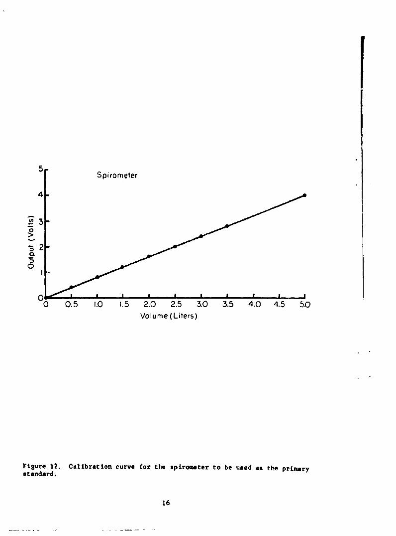
the output voltage of which varies linearly with volume. This output voltagewas previously calibrated in terms of volume, as shown in Figure 12, by intro-ducing into the spirometer known volumes of air from a calibrated cylinder*,ena-hllzr,!h4a t-a bc ;.. ... a. ... .,UL" " uL all M1 ub1 *ue tcalibrations. The output voltage of the impedance pneumograph was plottedversus the volume of respired air and a linear relaLionrhip wax fo, .nre to evlatas is indicated in Figure 13. Figure 5 is a plot of volume versus time as re-corded by the impedance pneumograph and the spirometer under static conditions.
RESULTS OF IMPEDANCE PNEUMOGRAPH EXPERIMENTATION
Position and Weight of Subject
The position of the subject was not found to have any effect on thelinear response of the pneumograph to respiratory volume, although the relativeoutput of the pneumograph for a given volume change was affected as indicatedon the following chart:
POSITION OF SUBJECT RELATIVE OUTPUT (STANDING-I.00)
Standing 1.00Sitting .78Lying on back .71Lying on "hot" electrode .36Lying on common electrode .78
Similarly, the relative output of the pneumograph varies depending onsuch physical characteristics of the subject as chest circumference and amountof subcutaneous fat.
Apparently, the relative sensitivity was affected largely by thepressure applied to the electrodes which in turn was affected by the weightof the subject.
Baseline Shifts due to Leg Raising, Mueller and Valsalva Maneuver
With the subject lying on his back and holding his breath, a deflectionof baseline was noted when his legs were raised. As shown in Figure 14, thisdeflection was in the direction of an inspiration (decreased impedance) and
was presumably caused by an increase in pulmonary blood volume. In support of
this theory, Figure 15 shows a similar deflection caused by the subject perform-
ing a Mueller maneuver and an opposite deflection which was caused by the
subject performing a Valsalva maneuver which causes a decrease in pulmonaryblood volume.
*George K. Porter Co., Hatfield, Pa. Vol-u-meter
15
1
5 JSpirometer
4-
0
0
0 0.5 1.0 1.5 2.0 2.5 3.0 3.5 4.0 4.5 50
Volume (Liters)
Figure 12. Calibration curve for the spirometer to be used as the primarystandard.
16
10
9I00
8
7
00
"-5
0
3
0
2
00 I 2 3 4 5 6
Volume (Liters)
Figure 13. Calibration curve for the impedance pneumograph shown in Figure 1.
17
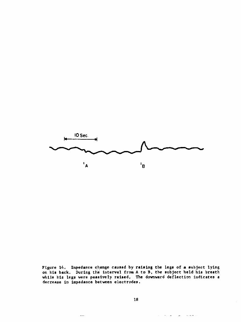
10 Sec.
'A '8
Figure 14. Impedance change caused by raising the legs of a subject lyingon his back. During the interval from A to B, the subject held his breathwhile hie legs were passively raised. The downward deflection indicates adecrease in impedance between electrodes.
18

A B C D
Figure 15. Impedance changes caused by the subject performing a Muellermaneuver (interval A to B) and a Valealva maneuver (interval C to D).
19

U
Effects of Dielectric
The manner in which the metallized cloth electrodes were insulatedfrom the subject's skin proved to be quite critical for reasons which are notyet explainable. The majority of the experiments performed with the pneumograph
.... ...- *-.. .- - ---- -a. UgwlciLriC materiaL. several variationsof this method were tried with drastic changes in the accuracy of the pneumograph Ioutput. For example, the interposition of thrae C .. f. su..... ,-, -.....• . .... .- j-J -' ,- M -U r&&ula gauze betweenthe plastic and the subject's skin resulted in an output that was "clipped" atboth inspiratory and expiratory extremes as is shown in Figure 16. A similarinterposition of two additional layers of polyethylene film in place of thegauze produced similar distortions of output.
DISCUSSION
The exact nature and cause of the variations in transthoracic impedancemeasured by this device have not yet been ascertained. Other investigatorshave reported (5) that the primary component of the impedance which varies withrespiration is the resistance while the reactive component remains essentiallyconstant. Other speculations implicate variations of blood volume in the chest,air in the lungs, or lung tissue density as being responsible for the impedancechanges noted (2, 6, 7). In any case, the impedance between the electrodes asmeasured with the pneumograph, varies linearly with the volume of air in thelungs.
20

10 Sec.
B PV
Figure 16. "Clipping" of the pneumograph output (Trace A) at high inspiratoryand expiratory levels caused by the interposition of three layers of surgicalgauze between the insulated electrodes and the subject's chest. Trace B isthe wedge spirometer output.
21

References
1. Allison, R. D., E. L. Holmes, and J. Nyboer. Volumetric dynamics ofrespiration as measured by electric impedance plethysmography. J. AppliedPhysiol. 19: 166, 1964.
2. Geddes, L. A., H. E. Hoff, D. H. Hickman, and A. G. Moore. The impedancepneumograph. Aerospace Med. 33! 2R; 19627.
3. Goldensohn, H. S. and L. Zablow. An electrical impedance spirometer.J. Appl. Physiol. 14: 463, 1959.
4. Geddes, L. A., H. E. Hoff, D. M. Hickman, H. Hinds, and L. Baker.Recording respiration and the electrocardiogram with common electrodes.Aerospace Med. 33: 791, 1962.
5. Baker, L. E., L. A. Geddes, and H. E. Hoff. Quantitative evaluation ofimpedance spirometry in man. Amer. J. Med. Etectronics 4: 73, 1965.
6. Nyboer, J. Plethysmography: Impedance. Medical Physics Vol. It. editedby Otto Glasser. The Year Book Publishers, Inc., Chicago, Ill., 19T0, p. 736.
7. Nyboer, J. Electrical Impedance Plethysmography: Electrical ResistiveMeasure of the Blood Pulse Volume, Peripheral and Central Blood Flow. CharlesC. Thomas, Springfield, 111., 1959.
22

Bibliography
1. Allison, R. Flow determination based on the end systolic gradient of pulsevolume curves using the electrical impedance plethysmograph. (Master's thesis)Wayne State University, Detroit. Mich. 1960.
5 2. Kaufman, W., and F. D. Johnston. The electrical conductivity of the tissuesnteat the heart and its bearing on the distribution of the cardiac action currents.Am. Heart J. 26: 42, 1943.
3. Kubicek, W. G., E. Kinnen, and A. Edin. Calibration of an impedancepneumograph. J. Aonlied Physiol. 19 (3): 557, 1964.
4. Mann, H. The carpacigraph. A new instrument for measuring cardiac output.Trans.Am. Coll, Cardiol. 3: 162, 1953.
5. Mead, J. and J. L. Whittenberger. Physical properties of human lungsmeasured during spontaneous respiration. J. Avvlied Physiol. 5: 779, 1953.
6. Powers, S. R. Jr., C. Schaffer, A. Bobo, and Y. Nahamura. Physical andbiologic factors in impedance plethysmography. Surlerv 44: 53, 1958.
7. Schwann, H. P. aid C. F. Kay. Capacitive properties of body tissues.Circulation Res. 5: 439, 1957.
8. Stead, W. W., H. S. Wells, N. L, Gault, J. Ognanovich. Inaccuracy of theconventional water-filled spirometer for recording rapid breathing. J. Appl.Physiol. 14: 448, 1959.
9. Wade, 0. L. Movements of the thoracic cage and diaphragm in respiration.J. Physiol. (London) 124: 193, 1954.
23

UNCIASS .Xff._____Security C, t'~ification
DOCUMENT CONTROL DATA - R&D(Securty close ifdcsti on of ititie, body of abstract and Indexnga~n n 'otalimf must be entered whe the or tell report is fees ileod)
1O0I1 INA TIN A G~Yatlra uhg REPORT SECURITY C LASSIFICATION
eroaed ica ¶esarcI Deoartmerit -- 2 -I-1 1US.Naval Air Development Center UM16"NLYIEW IJohsvileWarmitister, Pa. bGRU
3. REPORT TITLE
A Quantitative Impedance Pneumograph
4. DESCRIPTIVE NOTES (Type of report and inchuaavit dael*)
Phase ReportS. A UTHOR(S) (Last msw. first note, hiltiotl)
Bergey, George E. Hamilton, William A.Sipple, William C. Squires, Russell D.
S. REPORT DATE To. TOTAL NO. OF PAGES 7 b. NO. or Start
10 November 1966 23 9$a. CONTRACT OR GRANT NO. 9S9. ORIGINATORG REPORT N4UM8EW8)
6L PROJ9C T NO. NADC -MR-6622
Weptask R360 FR 1.02/2021/ROl 101 01(E. .501S. ZTNKRn~ %PORT NO(S) (Any othernumnbo,. Sholmaybe assi1,ed
d.10. AV A IL AIILITY/LIMITATION NOTICES
Distribution of this Document to Unlimited.
11. SUPPLEMENTARY NOTES 12. SPONSORING MILITARY ACTIVITY
13. ABSTRACT
This report describes an impedance pneumograph capable of measuringquantitatively respiratory volumes. Features of this system include the useof a higher frequency (300 KHa) excitation voltage than is normally used inimpedance pneumography and the use of pasteless electrodes which are insulatedfrom the subject by a layer of polyethylene, thus forming a capacitive couplingof the electrodes to the subject and eliminating the problems associated withskin-to-electrode impedance changes. A near perfect empiric correlation wasfound to exist between the transthoracic impedance measured by this device andpulmonary volume.
DD FJA11 1473 UNCLASSIFIEDSecurity Classification
UNCLASS IFIEDSecurity Classification_______ -
14.~KE WORDS_______________________ 1nL~ LINK A = = LINK CWT WTL
1. Impedance prioumographI2. Respiration3. Biotelemetry4. Capacitively coupled electrodes
INSTRUCTIONS1. ORIGINATING ACTIVITY: Enter the name and address imposed by security classification. using standard statementsof the contractor. subcontrector, grante*, Department of Do- such on:,@no* activity or other organization (coaporate author) issuing (1) "Qualified requesters may obtain copies of thisthe report. report from DDC. "2a. REPORT SECURITY CLASSIFICATION: Enter the over- (2) "Foreign announcement siod dissemination of thisall security classification of the report. Indicate artether"Restricted Data" is include&. Marking is to be in acord- report by DDC Is not authorized."
nce with appropriate security regulations. (3) 1"U. &. Goverament agencies may obtain copies of26. ROUP Auomatc dwngrdin ii pecfiedin Dl-thi report directly from DDC. Other qualified DDC
rective 5200. 10 and Armed Forces Industrial Manual. Entsersal euetthogthe group number. Also, wheon applicable, show that optionalmarkings have been used for Group 3 and Group 4 as author- (4) 1"U. &. military agencies may obtain copies of thisized, report directly from DDC. Other qualified users3. REPORT TITLE: Enter the comoplete report title in all shall request throughcapital letters. Title* in all cases should be unclosesfied.oIf a misvningful title cannot be selected without classifics-,lion, show title classification in all capitals in parentheeis (5) "All distribution of this report Is controlleo. Qual-immediately following the title. 1used DDC users shall tequest through4. DESCRIPTIVE NOTES: If appropriate, enter the type of __________________
retport, e.gA., interim, progress, summery, annual, or final. If the report has been furnished to the Office of TechnicalGive the inclusive dates when a specific reporting period is services, Department of Commerce, for sale to the pubhlic, Indi.covered. cat* this fact and enter the price, if known.S. AUTFIIR(S): Enter the name(*) of authwr(s) as shownl on I L SUPPLEMNTARY NDT2& Use for additional explana.or in the report. Enter last name, first name, middle Initial, tory notes.If m~ilitary, show rank and breanch of service. The name ofthe principal author is an absolute minimum requirement. 12. SPONSORING MILITARY ACTIVITY: Enter the name of
the departmental project office or laboratory sponsaoring (par-6. REPORT DATE. Enter the date of the report as day, ing4 for) the reseerch and development. Include address.month, year; or month, year. If more then one date appears 3 BTAT ne nasratgvn re n ataon the report, use date of publication.13ABTATEtraabrctgvn bieed(cul
summary of the document Indicative of the report, eyen though7a. TOTAL NUMBER OF PAGES. The total page count it nay also appear elsewhere in the body of the tschnical reo-should follow normal pagination procedures, Lae., enter the port. If additional apace is required, a continuation sheet shell'number of pages containing information. be attached.7b. NUMBER OF REFERENCE&: Enter the total number of It is highly desirable that the abstract of classified reportsreferences cited in the report. be unclassified. Each paragraph of the asbtrsct shall end withS.. CONTRACT OR GRANT NUMBER: If appropriate, enter an indication of the military security classification of the in-the applicable number of the contract or grant under which formation in the paragraph, represented as (rt), (s). (c), or (u).the report was written. There Is no limitation on the length of the abstract. Ho0w-S~b, B.&, kAd. PROJECT NUMBER: Enter the appropriate ever, the suggested length Is from li to 212 word*.military department identification, such aso project number, 1. YWOD: eywdsaetcnalymnngutrmsubproject number, system numbers, task number, etc.14 YWOD:Kywrsaetboal mnigutrs
or short phrases that characterize a report and may be used as9s. ORIGINATOR'S REPORT NUMBER(S): Enter the offi- Index entries for cataloging the report. Key words must hecial report number by which the document will be Identified selected so that no security classification is required. Moenti-and co' traoled by the originating activity. This number must fiers, such a. equipment model designation, trade name, militarybe u niý.ie to this report. project code name. gographic location, may he used as key9b. OTHER REPORT NUMABER(S): If the T,.port has been words but will be followed by an Indication of technical con-
apsi gned any oth &r report numbers (either by the orldinotor test. The assignment of links, roles, and weights Is optional.or by the sapnsot). also enter this numbee(s).10. AVAIL ABILITY/LIMITATION NOTICES: Enter any lim-itations on further iassemination of the report, other then thosel
D D,! JAN 54 1473 (BACK) rnjAi*@J=nLacurity Classification


![INDEX [lib3.dss.go.th]lib3.dss.go.th/fulltext/index/620-629/621.381gib.pdf · oscillator, 211 photodiode, 149 . INDEX. photosensitive, 147, 149 ... kilohertz, kilohm, 4 ... modular](https://img.pdfslide.net/doc/110x75/5aa76a7e7f8b9a294b8c0965/index-lib3dssgothlib3dssgothfulltextindex620-629621-211-photodiode.jpg)


![FLOW-INDUCED VIBRATIONS OF A LIGHT … · FLOW-INDUCED VIBRATIONS OF A ... non-linear oscillator for self-limiting its vibration amplitude are ... [13],OngorenandRockwell[14,15],Blevins[16],MittalandTezduyar](https://img.pdfslide.net/doc/110x75/5b83b77d7f8b9a31608def45/flow-induced-vibrations-of-a-light-flow-induced-vibrations-of-a-non-linear.jpg)