Embed Size (px)
Citation preview
Connecticut Siting Council Docket No. 272
Development & Management Plan for the
Middletown-Norwalk 345-kV Transmission Line Project
East Devon Substation
September 2006
Development & Management Plan
for the
Middletown-Norwalk 345-kV Transmission Line Project
East Devon Substation
Connecticut Siting Council
Docket No. 272
Submitted By: The Connecticut Light and Power Company
September 2006
Prepared by: Burns & McDonnell Engineering Company, Inc
TC-1
TABLE OF CONTENTS 1.0 INTRODUCTION........................................................................................................... 1-1
1.1 Project Description............................................................................................. 1-2 1.2 Conditions .......................................................................................................... 1-3 1.3 Consultations...................................................................................................... 1-3
2.0 DRAWINGS AND SITE INFORMATION ................................................................... 2-1
2.1 Key Map............................................................................................................. 2-1 2.2 Plan Drawings .................................................................................................... 2-1 2.3 Land Ownership ................................................................................................. 2-1 2.4 Public Roads and Lands ..................................................................................... 2-1 2.5 Topography and Grading.................................................................................... 2-1 2.6 Structure and Foundation Locations................................................................... 2-1 2.7 Access Points for Construction .......................................................................... 2-2 2.8 Vegetation and Clearing..................................................................................... 2-2 2.9 Environmentally Sensitive Areas ....................................................................... 2-2 2.10 Existing Underground Utilities .......................................................................... 2-2 2.11 Staging Area and Construction Facilities ........................................................... 2-2
3.0 CONSTRUCTION INFORMATION ............................................................................. 3-1
3.1 Timber and Snag Trees....................................................................................... 3-1 3.1.1 Marketable Timber................................................................................ 3-1 3.1.2 Snag Trees ............................................................................................. 3-1
3.2 Construction And Rehabilitation Procedures ..................................................... 3-2 3.2.1 Water Crossing Techniques................................................................... 3-2 3.2.2 Sedimentation and Erosion Control Procedures.................................... 3-2 3.2.3 Precautions for Protected Species ......................................................... 3-2 3.2.4 Restoration of Hydrologic Features ...................................................... 3-2 3.2.5 Protection of Cultural Resources........................................................... 3-2 3.2.6 Herbicide Use........................................................................................ 3-2 3.2.7 Public Recreation Areas ........................................................................ 3-3 3.2.8 Disposal and Maintenance Procedures.................................................. 3-3 3.2.9 Blasting Procedures............................................................................... 3-3 3.2.10 Rehabilitation Plans............................................................................... 3-3 3.2.11 Independent Environmental Consultant ................................................ 3-3
4.0 NOTICES AND REPORTS............................................................................................ 4-1
4.1 Staging and Material Laydown Areas ................................................................ 4-1 4.2 Notices to the Council ........................................................................................ 4-1
4.2.1 Notice of Beginning .............................................................................. 4-1 4.2.2 Notice of Changes to D&M Plan .......................................................... 4-1 4.2.3 Notice of Completion ............................................................................ 4-1
4.3 Notice to Municipalities ..................................................................................... 4-1 4.4 Notice to Landowners ........................................................................................ 4-1 4.5 Monthly Reports................................................................................................. 4-1 4.6 Final Report........................................................................................................ 4-1
TC-2
5.0 ADDITIONAL ELEMENTS PER COUNCIL ORDER................................................. 5-1 5.1 Decision and Order Checklist…………………………………………………..5-1 5.2 Supplemental Plans and Information…………………………………………...5-2
6.0 PROJECT SCHEDULE .................................................................................................. 6-1 APPENDICES
APPENDIX A – DRAWINGS AND PHOTOS Exhibit 1 Key Map Exhibit 2 Aerial Photograph Exhibit 3 General Arrangement Exhibit 4 Site Grading Plan
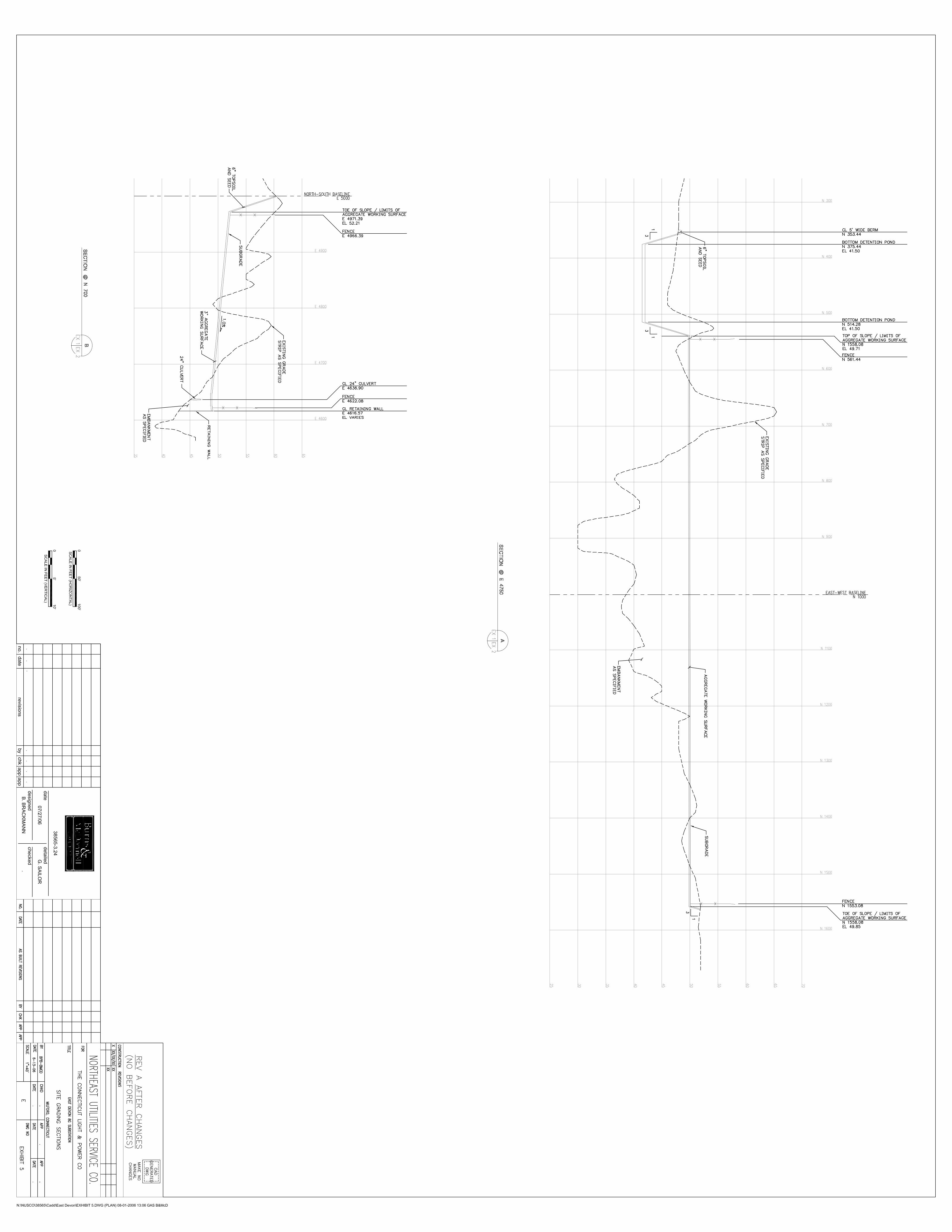
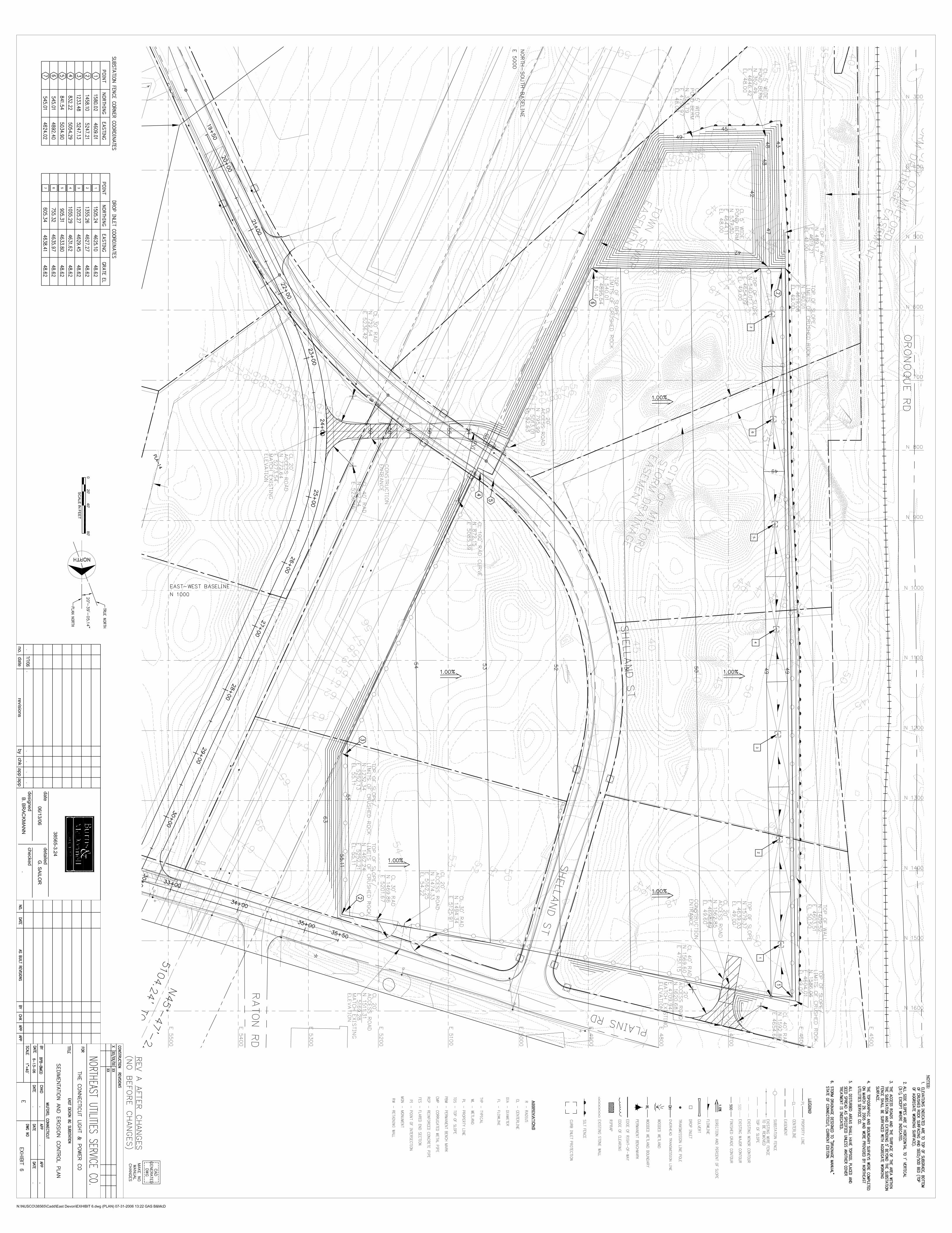
Exhibit 5 Site Grading Sections Exhibit 6 Sedimentation and Erosion Control Plan
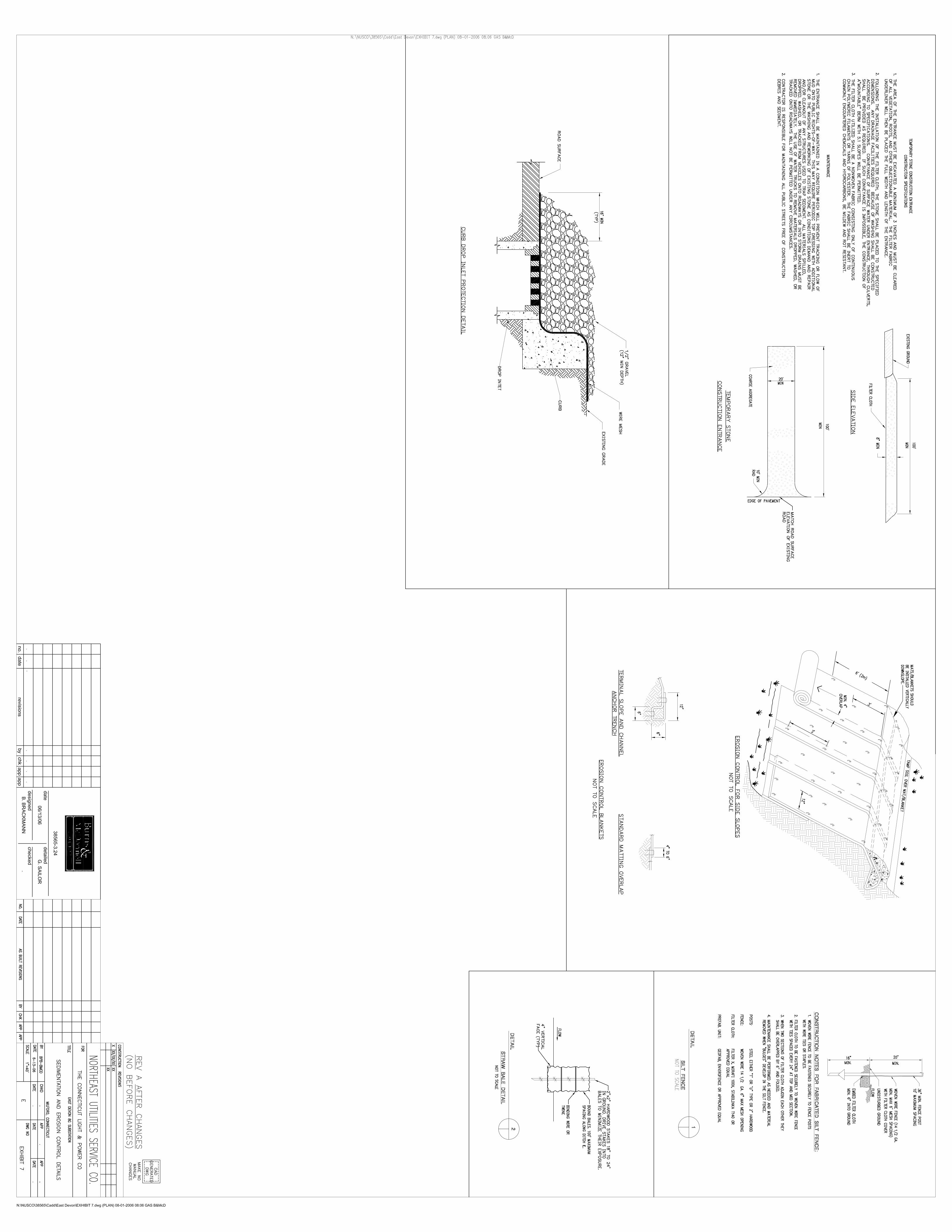
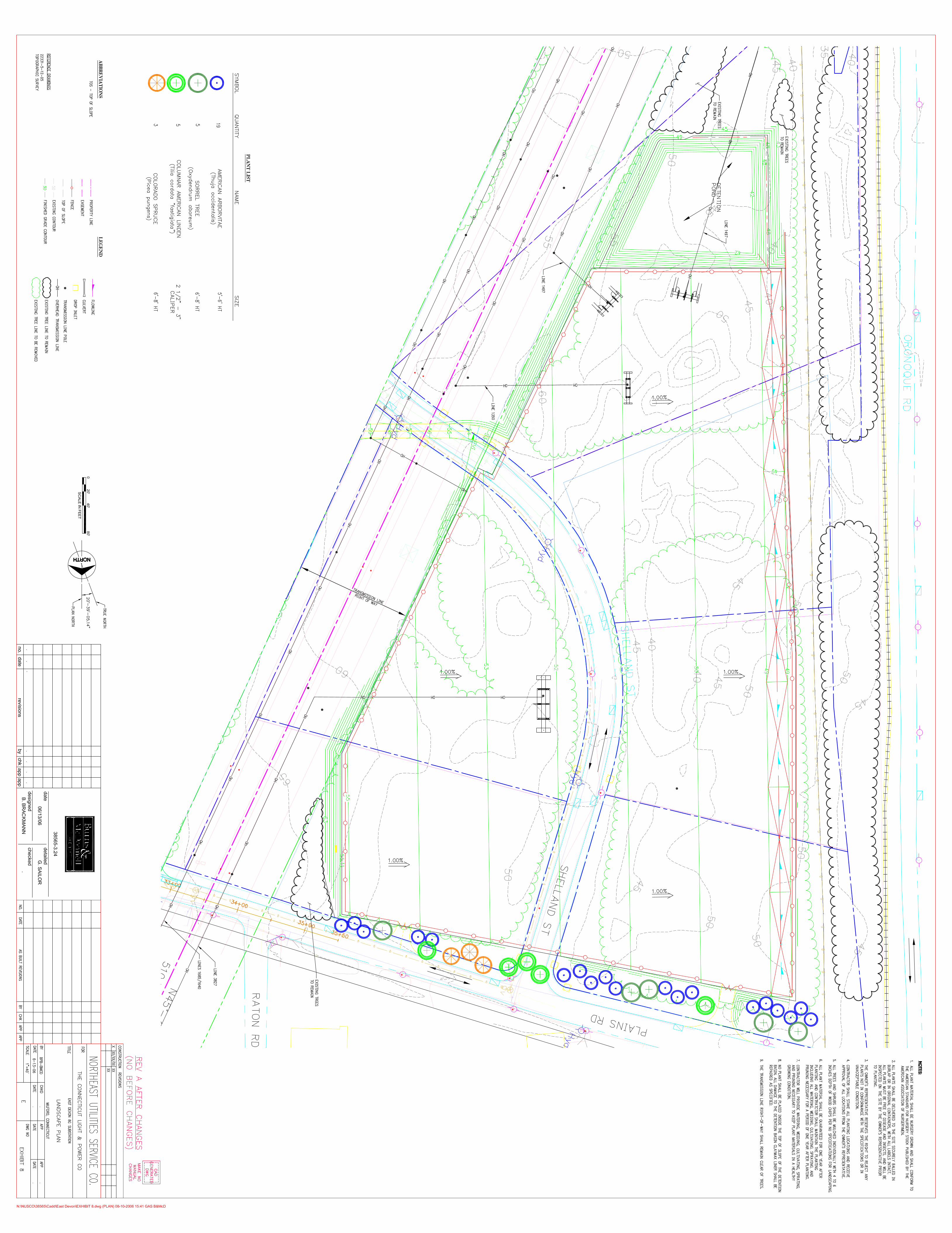
Exhibit 7 Sedimentation and Erosion Control Details Exhibit 8 Landscape Plan
APPENDIX B – DOCKET NO. 272, SELECTED PORTIONS OF DECISION AND ORDER
APPENDIX C – D&M PLAN CHANGE APPROVAL PROCESS
Middletown-Norwalk Project D&M Plan East Devon Substation
1-1 9/27/2006
1.0 INTRODUCTION The Connecticut Light and Power Company (CL&P) hereby submits this Development and Management (D&M) Plan for the East Devon Substation located in the City of Milford, a part of the Middletown-Norwalk Project (the Project), in accordance with the Connecticut Siting Council (Council) Decision and Order for Docket No. 272 of April 7, 2005, and pursuant to Sections 16-50j-60 through 16-50j-62 of the Regulations of Connecticut State Agencies, Requirements for a right-of-way development and management plan. The Project consists of approximately 69 miles of 345-kV transmission line from CL&P’s existing Scovill Rock Switching Station (located in the City of Middletown in Middlesex County), through New Haven County to CL&P’s existing Norwalk Substation (located in the City of Norwalk in Fairfield County). The Project will include approximately 45 miles of overhead transmission line construction and 24 miles of underground transmission line construction. The overhead portion of the Project will extend from the Scovill Rock Switching Station in the City of Middletown to the East Devon Substation in the City of Milford. The underground portion will extend from the East Devon Substation to the Norwalk Substation in Norwalk. In addition to East Devon Substation, the Project will include the construction of one other new electric substation (Singer in the City of Bridgeport) and a new Switching Station (Beseck in the Town of Wallingford) as well as modifications to the existing Norwalk Substation and Scovill Rock Switching Station. CL&P will own all overhead portions of the Project, as well as that portion from East Devon Substation to the first splice-vault west of the Housatonic River. CL&P ownership continues from the Singer Substation to the Norwalk Substation. The United Illuminating Company (UI) will build and own the Singer Substation and from the Singer Substation to the first splice-vault, inclusive of the splice-vault, west of the Housatonic River, a distance of approximately 5.75 miles. CL&P plans to submit thirteen D&M plans for its portion of the Project. The D&M plans will be developed based on the type of construction and geographic location along the route, as follows:
Switching Stations and Substations (4 D&M plans) • Scovill Rock (Middletown) – Approved by the Council on August 25, 2005 • Beseck (Wallingford) – Approved by the Council on February 22, 2006 • East Devon (Milford) • Norwalk (Norwalk)
Overhead Lines (4 D&M plans)
• Segment 1a: Scovill Rock Switching Station to Chestnut Junction, Oxbow Junction to Beseck Switching Station (with the exception of the Royal Oak Bypass), and Black Pond Junction to Beseck Switching Station
(Middletown, Haddam, Durham, Middlefield, Meriden, Wallingford) – Approved by the Council on March 8, 2006
• Segment 1b: Royal Oak Bypass (Middletown) – Approved by the Council on August 31, 2006.
• Segment 2a: Beseck Switching Station to Cheshire/Hamden Town line (Wallingford, Cheshire) – Approved by the Council on June 7, 2006 • Segment 2b: from Cheshire/Hamden Town line to East Devon Substation
(Hamden, Bethany, Woodbridge, West Haven, Orange, Milford) – Approved by the Council on August 31, 2006, with the exception of that portion of Segment 2b between Rimmon Road and Center Road in the Town of Woodbridge, which is still under review.
Middletown-Norwalk Project D&M Plan East Devon Substation
1-2 9/27/2006
Underground Lines (4 D&M plans)
• Segment 3: East Devon Substation to UI ownership point in Stratford (Milford, Stratford) – Approved by the Council on March 22, 2006
• Segment 4a: Singer Substation to Fairfield/Westport Town line (Bridgeport, Fairfield) – Approved by the Council on February 22, 2006
• Segment 4b: Sasco Creek to Father Conlon Place in Norwalk (Westport, Norwalk) – Approved by the Council on June 27, 2006
• Segment 4c: Father Conlon Place in Norwalk to Norwalk Substation (Norwalk)
Underground Watercourse and Railroad Crossings (1 D&M plan) (Milford, Stratford, Bridgeport, Fairfield, Westport, Norwalk) - Filed with the Council on September 8, 2006
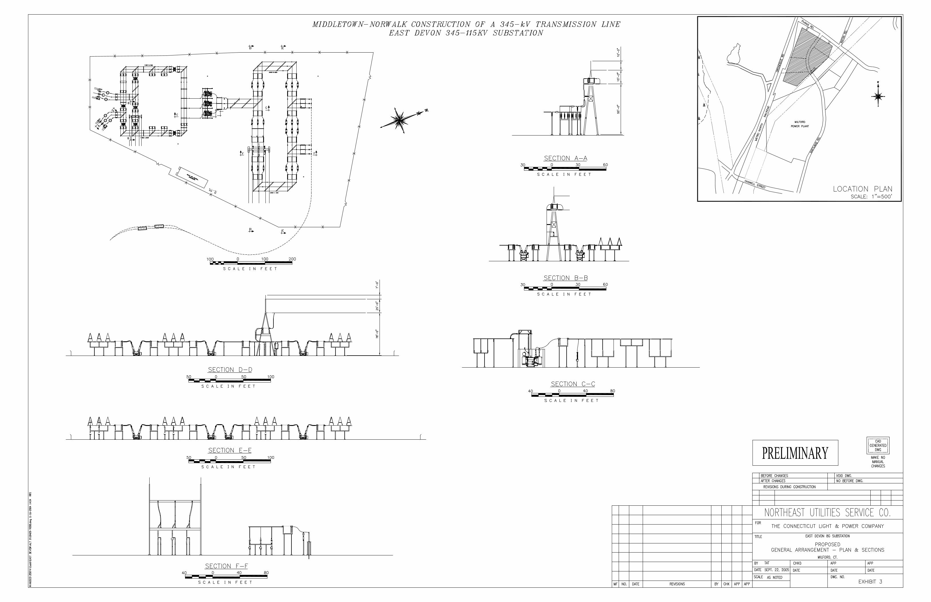
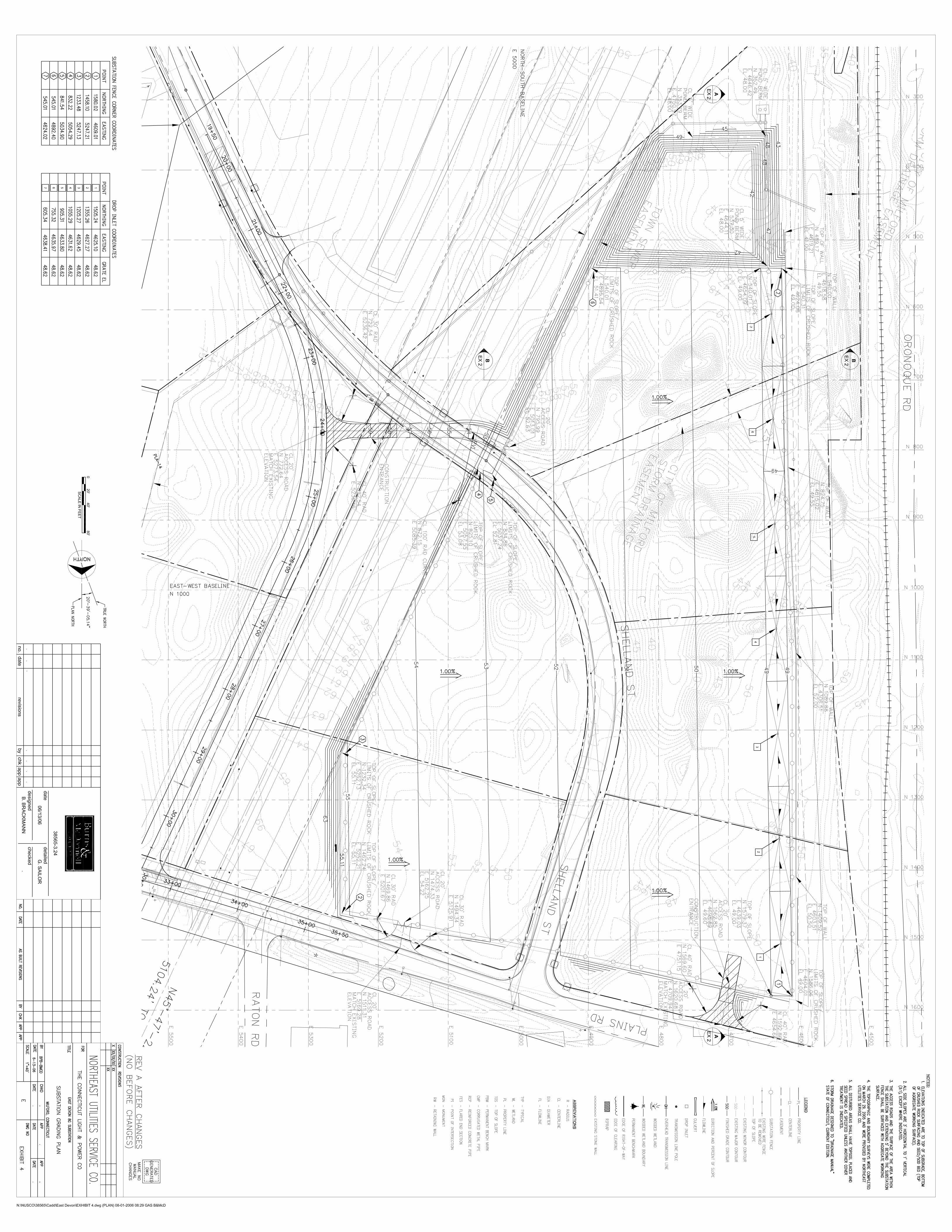
1.1 PROJECT DESCRIPTION This D&M Plan covers the work associated with the construction of the new East Devon 345/115-kV Substation. Exhibit 3 of Appendix A depicts the general layout of the East Devon Substation and the terminus of two (2) underground 345-kV transmission lines, one (1) overhead 345-kV transmission line, and three (3) 115-kV transmission lines. Equipment to be installed includes one (1) 345-kV line terminal structure, seven (7) 345-kV circuit breakers, sixteen (16) 345-kV switches, three (3) single phase 345/115-kV auto transformers, three (3) 115-kV line terminal structures, seven (7) 115-kV circuit breakers, twenty-five (25) 115-kV switches, six (6) single phase 115-kV current limiting series reactors, riser structures, aluminum bus, bus supports, a standby generator for station service power and area lighting. Four lightning masts will be installed at the East Devon site. Three will be 110 feet tall and one will be 80 feet tall. An equipment enclosure will be constructed for protective relay, control and communications equipment. Foundations will be installed for all equipment. Chain link fencing will be installed around the perimeter of the site. A ground grid and electrical raceway will be installed below the finished grade. The site will be surfaced with trap rock. Cable trench with concrete covers will be installed flush with the crushed rock surface. Also shown in Appendix A, Exhibit 4 are proposed permanent access roads, retaining walls and drainage structures for the work. The estimated total height of the 345-kV line termination structure is 110 feet, 103 feet for the structure plus a 7-foot lightning mast. The estimated total height of the 115-kV line termination structures is 80 feet, 70 feet for the structure and 10-foot lightning mast. The 345-kV structures and lightning masts will be the tallest structures at the Substation. The height of the 345-kV bus work will be approximately 25 feet for the low buses and 41 feet for the high buses. The height of the 115-kV bus work will be approximately 17 feet for the low bus and 25 feet for the high buses. The high buses are the main buses, a typical design for a breaker-and-a-half switching station. Overall dimensions of the fenced area will be approximately 1035 feet by 650 feet. The site is currently populated by trees and undergrowth that will be cleared and hauled away during construction. Site work will be required to achieve final grade. The grading plan (Appendix A, Exhibit 4) is included as a part of this document. The existing Shelland Street will be relocated immediately to the east of the transmission right-of-way, and be turned over to the City of Milford upon completion (refer to drawing LL-01 in the September 6, 2006 change request for the Segment 3 D&M Plan for the location of the relocated Shelland Street). After construction is complete, a landscape buffer will be planted to screen views from off-site. The landscaping plan is included as part of this document in Appendix A, Exhibit 8.
Middletown-Norwalk Project D&M Plan East Devon Substation
1-3 9/27/2006
1.2 CONDITIONS In addition to the Requirements for a right-of-way development and management plan found in Sections 16-5-j-60 et seq. of the Regulations of Connecticut State Agencies, the Council stipulated certain requirements for the D&M plans in conditions 14-21 of its Decision and Order. A copy of this portion of the Decision and Order is provided in Appendix B. Those requirements have been incorporated in this D&M Plan either directly or by reference. An individual permit from the U.S. Army Corps of Engineers is required for the proposed work. The General Permit for the Discharge of Stormwater and Dewatering Wastewaters from Construction Activities (DEP-PED-GP-015) from the Connecticut Department of Environmental Protection (DEP), required for the Project including the East Devon Substation, was registered by the DEP April 16, 2006. A Coastal Area Management Permit from the City of Milford will be required prior to initiation of construction activities. 1.3 CONSULTATIONS Project personnel met with City of Milford (Milford) officials on April 20, 2006 at the Milford City Hall to discuss the relocation of Shelland Street and utilities that run through the East Devon Substation site. Project personnel included Jim Long, Michael Green and Michael Feodorov of CL&P, and John Yarbrough of Carmody and Torrance. Representatives for Milford included Mayor James Richetelli, City Attorney Marilyn Lipton, City Planner David Sulkis, and the Director of Public Works, Bruce Kolwicz. Items discussed included Siting Council approval and the Project need for the relocations. Discussions also included the need for Milford to accept Shelland Street and the relocated portion of Shelland Street as City streets. All parties agreed that plans for the relocation of Shelland Street and existing utilities should be prepared for review as soon as possible. The plans for the relocation of Shelland Street and existing utilities were subsequently submitted to the City of Milford and have been approved.
Middletown-Norwalk Project D&M Plan East Devon Substation
2-1 9/27/2006
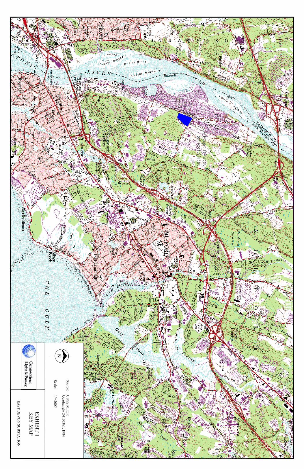
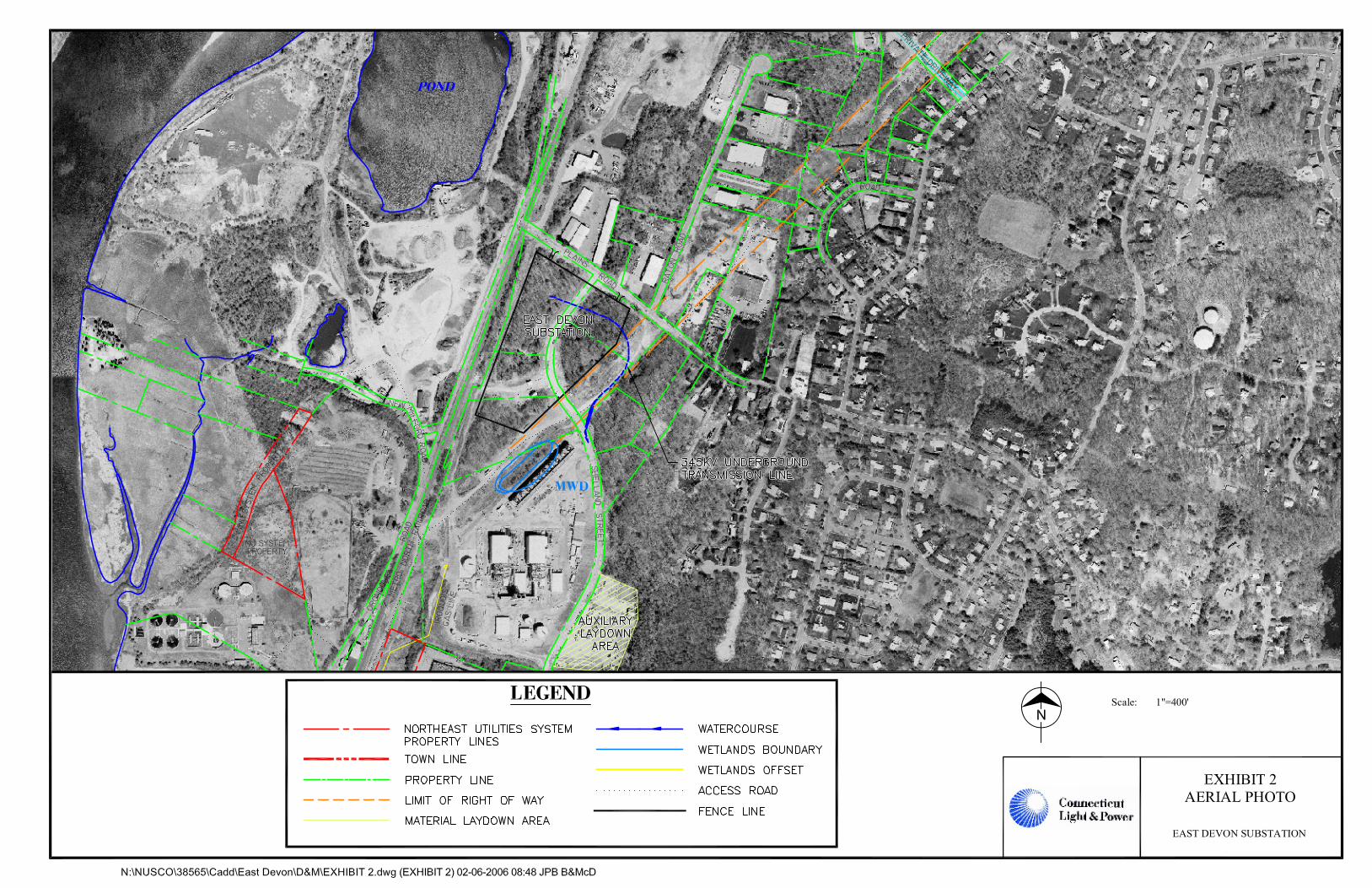
2.0 DRAWINGS AND SITE INFORMATION The East Devon Substation will be a new CL&P 345-kV and 115-kV facility contained inside a fenced area with a surface of trap rock. CL&P performed and reported on extensive research on environmental conditions and cultural resources as part of the Docket No. 272 proceedings before the Council. The following provides descriptive information regarding the existing conditions at the site and the design and construction that will take place at East Devon Substation as part of the Project. As described below, this information is also shown on the drawings included in Appendix A. 2.1 KEY MAP The East Devon Substation is located at the southeast corner of the intersection of Oronoque Road and Plains Road in Milford. The location is shown on the Key Map (Appendix A, Exhibit 1), as well as on an aerial photograph (Appendix A, Exhibit 2). 2.2 PLAN DRAWINGS In addition to the key map and aerial photograph, this D&M Plan contains drawings depicting the General Arrangement Plan and Sections (Appendix A, Exhibit 3) and Site Grading Plan (Appendix A, Exhibits 4 and 5). The General Arrangement Plan and Sections provides locations of the components to be installed at the Substation. Drainage patterns, with locations for installation of sediment and erosion control materials, are shown on the Sedimentation and Erosion Control Plan (Appendix A, Exhibit 6). 2.3 LAND OWNERSHIP The entire Station site is currently owned by Jordan Realty, LLC, which has agreed to sell the parcel to CL&P. The closing of this sale is expected to occur in the near future. 2.4 PUBLIC ROADS AND LANDS No public lands cross or adjoin the proposed Substation property. The Waterbury Branch of the Metro North Railroad and Oronoque Road bound the site on the west. Plains Road borders the property to the north. Shelland Street, currently a private road, bisects the property and will be relocated as part of construction at the site. Ownership of the relocated Shelland Road will be transferred to the City of Milford after the City deems that the road meets the City’s construction standards. 2.5 TOPOGRAPHY AND GRADING Due to the relative flat topography, the site will only require minimal grading. A low area in the southwest corner of the site will be filled and a minor amount of earthwork will need to be performed on the entire site to level the high and low areas to achieve a uniform elevation. See attached site grading drawings provided in Appendix A, Exhibits 4 and 5. 2.6 STRUCTURE AND FOUNDATION LOCATIONS The approximate location and type of structures and foundations on the site are shown on the General Arrangement Plan and Sections in Appendix A, Exhibit 3.
Middletown-Norwalk Project D&M Plan East Devon Substation
2-2 9/27/2006
2.7 ACCESS POINTS FOR CONSTRUCTION Access to the site for construction, operation, and maintenance will be from two spurs off Plains Road and one off Shelland Street (Appendix A, Exhibit 4,). No improvements to either road will be necessary. 2.8 VEGETATION AND CLEARING Vegetation at the Substation site is primarily young. upland mixed hardwood forest as well as some scrub/shrub cover type. (see Volume 9 of the Application to the Council,, Segment 45) including maples, oaks and hickories. Two wetlands are present on the site. The clearing process involves:
• field survey to identify the boundaries of the Substation and key components requiring construction, such as access roads.
• preparatory clearing operation, starting with opening of access roads followed by clearing of the Substation site.
There will be no vegetation inside the fenced area of the East Devon Substation or up to 5 feet from the fence line after completion of the clearing process. 2.9 ENVIRONMENTALLY SENSITIVE AREAS There are no watercourse crossings, areas of high erosion potential or areas where there are federal or state protected species that will be affected by the construction at East Devon Substation. There are two wetlands that will be filled during construction of this Substation. These are described in Section 3.2.1. 2.10 EXISTING UNDERGROUND UTILITIES There are four underground utilities in or near the East Devon Substation site: water, gas, sanitary, and storm water. The water and gas lines will be re-directed to follow the re-alignment of Shelland Street. The existing storm drainage system associated with the present Shelland Street drains through a City of Milford easement crossing the proposed East Devon Substation Site. This storm water system will be removed and replaced by a new storm drainage system just south of the Substation as shown in Appendix A, Exhibit 4. The easements associated with the existing storm drainage system will be incorporated back into the CL&P property and a new City of Milford easement will be established for the new drainage system. The sanitary line will be relocated under the new Shelland Street and will tie into the existing sanitary sewer trunkline located adjacent to the site in the southeast corner; however, it will not be impacted by construction of the Substation. “Call Before You Dig” will be contacted to confirm the absence of any other underground utilities prior to construction. 2.11 STAGING AREA AND CONSTRUCTION FACILITIES The staging area for materials and equipment for the East Devon Substation construction will be on the Substation site or on a 5-acre parcel on Shelland Street to be leased by CL&P as additional staging. It will be the responsibility of the Construction Contractor to provide additional staging areas and/or construction facilities, if needed. Any additional staging and/or proposed construction locations will be submitted to the Council for approval using the Change Process described in Appendix C. The Construction Contractor’s office trailer will be on-site. Parking will be on the East Devon Substation site

Middletown-Norwalk Project D&M Plan East Devon Substation
2-3 9/27/2006
or on the auxiliary staging area on Shelland Street. Portable sanitary facilities will be used during construction. Temporary overhead phone, power lines and security lighting will be installed within the Substation during construction. Consistent with CL&P transmission system standards, permanent phone lines, power lines for station service and security lighting will be installed as part of the permanent facility.
Middletown-Norwalk Project D&M Plan East Devon Substation
3-1 9/27/2006
3.0 CONSTRUCTION INFORMATION This section contains information concerning construction practices and mitigation measures related to the construction of the East Devon Substation. 3.1 TIMBER AND SNAG TREES To maximize forest resource utilization, CL&P employed a professional forestry consulting firm to inventory trees on the properties affected by the construction and installation of the Project, including the construction of East Devon Substation. 3.1.1 Marketable Timber Trees identified to be removed during construction of the Project fall into three categories of marketability:
• Non-marketable Timber – Trees that are generally small, seedling and sapling sized, or larger trees with significant defects.
• Marginal Value Timber – Trees that are generally poletimber sized (6-11 inch diameter at breast height (dbh)) or larger trees with some defects. Common uses for these trees include fuelwood, pulpwood, and pallet wood. This category also includes larger sawtimber trees whose economic value has been decreased due to high harvesting costs.
• Marketable Timber – Trees that are sawtimber sized (12+ inches dbh), sound and reasonably accessible to harvesting. Uses for these trees include veneer and dimensional lumber products.
Utilization of the harvested trees will fall into one or more of the following categories:
• Chipped on Site – These trees are usually non-marketable or marginally marketable. • Cut, Trimmed and Piled on Site – The harvested trees are trimmed, piled and available to
neighboring landowners for use as fuelwood and other uses. This approach can be used in areas where the transportation of harvested wood has the potential for site impact.
• Removed from Site – The harvested trees and chips can be removed from site and be utilized at various mills. Markets, harvesting and transportation costs will determine the viability of this option.
All timber at the East Devon Substation site is in the non-marketable or marginal value timber categories and will likely be chipped on site and/or removed for fuelwood. 3.1.2 Snag Trees A snag tree is a standing tree in some stage of decay that has one or more biological and structural attributes usable by wildlife. Snag trees can be used for cavity and branch nesting, perches, insect production and cover. Existing snag trees will remain along the transmission corridor providing they meet all specifications for line clearance and safety. There is a constant supply of new snag trees being created along the ROW due to tree damage caused naturally by ice, wind, insects and disease.
Middletown-Norwalk Project D&M Plan East Devon Substation
3-2 9/27/2006
3.2 CONSTRUCTION AND REHABILITATION PROCEDURES Construction procedures for water crossings, sedimentation and erosion control, protected species, hydrologic features and cultural resource properties are described below.
3.2.1 Water Crossing Techniques There are no watercourse crossings associated with the construction of the East Devon Substation. Two wetlands, 300A and 300B, will be filled by the construction of the East Devon Substation. Wetland 300A is a wooded swamp. Wetland 300B is a shallow marsh/wet meadow. Mitigation for the loss of these wetlands is discussed in Section 3.2.10.
3.2.2 Sedimentation and Erosion Control Procedures Construction activities will comply with the 2002 Connecticut Guidelines for Soil Erosion and Sediment Control. Specific sedimentation and erosion control measures are shown on the Sedimentation and Erosion Control drawing in Appendix A, Exhibit 6. Details for typical sedimentation and erosion control measures are provided in Appendix A, Exhibit 7. Excess spoil material will be removed from the site by the contractor and disposed of in an approved location. Some spoil material may be retained for backfill.
Groundwater encountered during the drilling of foundations for Substation equipment will be discharged in accordance with the DEP Stormwater and Dewatering Wastewaters from Construction Activities General Permit GP-015.
3.2.3 Precautions for Protected Species Pursuant to consultation with the DEP Natural Diversity Database, there are no federal or state protected species located near the East Devon Substation.
3.2.4 Restoration of Hydrologic Features Surface drainage will be minimally altered during the construction of the Substation. All grading at the Substation is designed to utilize the detention basins.
3.2.5 Protection of Cultural Resources CL&P provided a Cultural Resources Assessment Survey as part of the Application to the Council. The survey found no known cultural resources located in or near the Substation site. Further information is needed to complete the Phase II cultural resource assessment. In accordance with the Council Decision and Order Item #21, CL&P has retained Raber and Associates to survey the East Devon Substation site prior to construction to determine if any unknown cultural resources eligible for inclusion on the National Register of Historic Places occur at the site. The Phase II survey report is anticipated to be complete for East Devon Substation by late 2006 with concurrence from the State Historic Preservation Officer (SHPO) of no significant adverse impacts to cultural resources.
3.2.6 Herbicide Use No herbicides will be used for clearing associated with construction. Normal maintenance of the Substation yard, however, will include treatment of vegetation with Environmental Protection Agency approved herbicides. Normal maintenance outside the fence will include both mechanical clearing and herbicide treatment. Such vegetation control will be performed on a regularly scheduled basis.
3.2.7 Public Recreation Areas The Milford Riders Motorcycle Club’s riding area is located northeast of the East Devon Substation site, north of Plains Road.
Middletown-Norwalk Project D&M Plan East Devon Substation
3-3 9/27/2006
3.2.8 Disposal and Maintenance Procedures The Contractor will remove all debris, excess rock and soil, including polluted or contaminated soils, and dispose of it in accordance with local, state, and federal regulations and with the Material Handling Guideline prepared for the East Devon Substation. No burning will occur at the Substation.
3.2.9 Blasting Procedures CL&P does not expect that blasting will be required during the construction of the Substation. If any blasting should subsequently be found to be necessary on this site or others, it will be performed by licensed blasting contractor(s), pursuant to the regulations of State and Local Fire Marshals. In addition, any blasting near CL&P’s existing transmission and distribution lines will be performed in accordance with CL&P’s guidelines. In general, blasting will be conducted in a manner that will maintain safe working conditions and avoid damage to adjacent areas and structures. Blasting will be conducted by registered blasters and monitored by blasting inspectors. The precautions that are taken during blasting include:
• Obtaining applicable state and/or local blasting permits; • Installing blasting mats as required; • Posting warning signals, signage and barricades; • Following procedures for safe storage, handling, loading, firing, and disposal of explosive
materials; and, • Conducting blasting between 7 am and 7 pm.
When necessary, blasting is performed to meet or exceed all applicable federal, state, and local requirements covering the use of explosives. Excessive vibration will be controlled by limiting the size of charges and by using charge delays, which stagger each charge in a series of blasts.
Pre-blast inspections will be performed at the discretion of CL&P and vibration monitoring will be performed during the blasting procedure.
Post-blast inspections will be performed, as necessary. All damage complaints alleged to be associated with construction activities will be investigated and the owner will be compensated for damages or appropriate repairs will be made if it is determined that the damage was caused as a direct result of the blasting.
3.2.10 Rehabilitation Plans All of the ground surface of the East Devon Substation and a perimeter up to 5 feet past the proposed chain link fence will be covered in trap rock. Planned landscaping elements to mitigate aesthetic impacts are shown in Appendix A, Exhibit 8.
Wetland restoration will not occur on-site as the two wetlands identified will be filled during the construction of the East Devon Substation. Mitigation for the loss of the two wetlands has been established as part of the U.S. Army Corps of Engineers Individual Permit for Sections 404 and 10 waters affected by the Project. The wetland mitigation plan was also reviewed and approved by the DEP during the preparation of the Section 401 Water Quality Certification. Mitigation consisting of wetland enhancement and creation will occur in the Eisenhower City Park in the City of Milford.
Middletown-Norwalk Project D&M Plan East Devon Substation
3-4 9/27/2006
3.2.11 Independent Environmental Consultant The Council approved BSC Group as the independent environmental consultant at its January 25, 2006 meeting.
Middletown-Norwalk Project D&M Plan East Devon Substation
4-1 9/27/2006
4.0 NOTICES AND REPORTS This section outlines requirements regarding notifications and reporting procedures per Section 16-50j-62 of the Regulations of Connecticut State Agencies. 4.1 STAGING AND MATERIAL LAYDOWN AREAS The staging and laydown area for this work will be designated within the Substation yard or on a 5-acre parcel to be leased by CL&P as additional staging located on Shelland Street. Temporary overhead phone and power lines and security lighting will be installed within the staging area. Staging and material laydown areas proposed for use and not on this list will be submitted to the Council for review and approval. 4.2 NOTICES TO THE COUNCIL Three types of notices are required by the Council for construction. Each type is described below.
4.2.1 Notice of Beginning CL&P will provide written notification to the Council a minimum of two weeks prior to the beginning of construction at the site, including clearing and access work.
4.2.2 Notice of Changes to D&M Plan For all segments of this Project, CL&P intends to utilize a uniform procedure for interfacing with the Council regarding any changes to approved D&M Plans, namely, the procedure that the Council has already approved in connection with the D&M Plan for Scovill Rock Switching Station. This model, which has also been successfully applied for the Bethel-Norwalk Project (Docket No. 217), is described in Appendix C.
4.2.3 Notice of Completion CL&P will provide the Council written notification of the completion of construction and site rehabilitation for the Substation.
4.3 NOTICE TO MUNICIPALITIES CL&P will provide written notification to the Chief Elected Official of Milford a minimum of three weeks prior to the beginning of construction. CL&P will also notify the Chief Elected Official when the work at the Substation is complete. 4.4 NOTICE TO LANDOWNERS CL&P will provide written notification to adjacent landowners a minimum of two weeks prior to the beginning of construction. 4.5 MONTHLY REPORTS CL&P will provide the Council with written monthly progress reports . 4.6 FINAL REPORT CL&P will provide a final report to the Council as required in Section 16-50j-62 of the Regulations of Connecticut State Agencies. The final report will contain the following information as prescribed in the regulations:
1. All agreements with abutters or other property owners regarding special maintenance precautions.
Middletown-Norwalk Project D&M Plan East Devon Substation
4-2 9/27/2006
2. Significant changes to the D&M Plan that were required because of the property rights of underlying and adjoining owners or for other reasons. 3. Location of non-transmission materials which have been left in place. 4. Actual construction cost of the facility including but not limited to the following:
• Clearing and access • Construction • Rehabilitation
Middletown-Norwalk Project D&M Plan East Devon Substation
5-1 9/27/2006
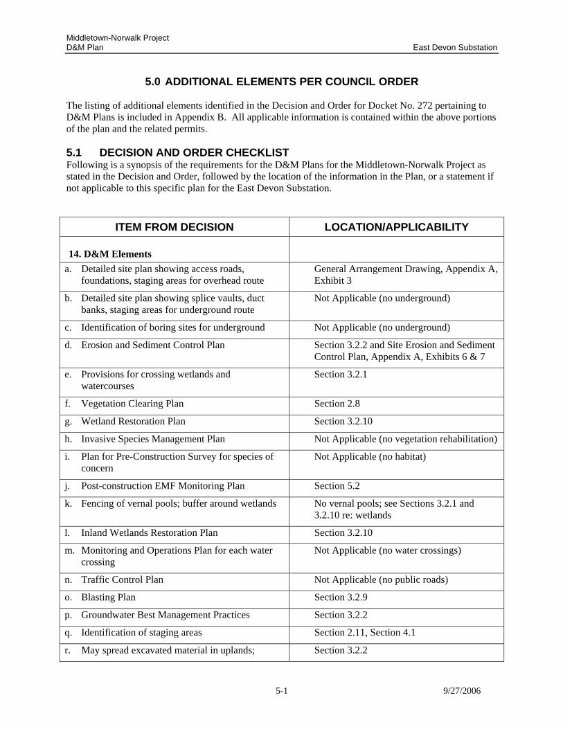
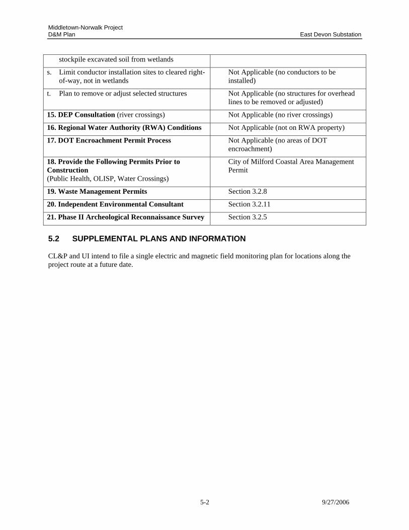
5.0 ADDITIONAL ELEMENTS PER COUNCIL ORDER The listing of additional elements identified in the Decision and Order for Docket No. 272 pertaining to D&M Plans is included in Appendix B. All applicable information is contained within the above portions of the plan and the related permits. 5.1 DECISION AND ORDER CHECKLIST Following is a synopsis of the requirements for the D&M Plans for the Middletown-Norwalk Project as stated in the Decision and Order, followed by the location of the information in the Plan, or a statement if not applicable to this specific plan for the East Devon Substation.
ITEM FROM DECISION LOCATION/APPLICABILITY
14. D&M Elements
a. Detailed site plan showing access roads, foundations, staging areas for overhead route
General Arrangement Drawing, Appendix A, Exhibit 3
b. Detailed site plan showing splice vaults, duct banks, staging areas for underground route
Not Applicable (no underground)
c. Identification of boring sites for underground Not Applicable (no underground)
d. Erosion and Sediment Control Plan Section 3.2.2 and Site Erosion and Sediment Control Plan, Appendix A, Exhibits 6 & 7
e. Provisions for crossing wetlands and watercourses
Section 3.2.1
f. Vegetation Clearing Plan Section 2.8
g. Wetland Restoration Plan Section 3.2.10
h. Invasive Species Management Plan Not Applicable (no vegetation rehabilitation)
i. Plan for Pre-Construction Survey for species of concern
Not Applicable (no habitat)
j. Post-construction EMF Monitoring Plan Section 5.2
k. Fencing of vernal pools; buffer around wetlands No vernal pools; see Sections 3.2.1 and 3.2.10 re: wetlands
l. Inland Wetlands Restoration Plan Section 3.2.10
m. Monitoring and Operations Plan for each water crossing
Not Applicable (no water crossings)
n. Traffic Control Plan Not Applicable (no public roads)
o. Blasting Plan Section 3.2.9
p. Groundwater Best Management Practices Section 3.2.2
q. Identification of staging areas Section 2.11, Section 4.1
r. May spread excavated material in uplands; Section 3.2.2
Middletown-Norwalk Project D&M Plan East Devon Substation
5-2 9/27/2006
stockpile excavated soil from wetlands
s. Limit conductor installation sites to cleared right-of-way, not in wetlands
Not Applicable (no conductors to be installed)
t. Plan to remove or adjust selected structures Not Applicable (no structures for overhead lines to be removed or adjusted)
15. DEP Consultation (river crossings) Not Applicable (no river crossings)
16. Regional Water Authority (RWA) Conditions Not Applicable (not on RWA property)
17. DOT Encroachment Permit Process Not Applicable (no areas of DOT encroachment)
18. Provide the Following Permits Prior to Construction (Public Health, OLISP, Water Crossings)
City of Milford Coastal Area Management Permit
19. Waste Management Permits Section 3.2.8
20. Independent Environmental Consultant Section 3.2.11
21. Phase II Archeological Reconnaissance Survey Section 3.2.5
5.2 SUPPLEMENTAL PLANS AND INFORMATION CL&P and UI intend to file a single electric and magnetic field monitoring plan for locations along the project route at a future date.
6-1 9/27/2006
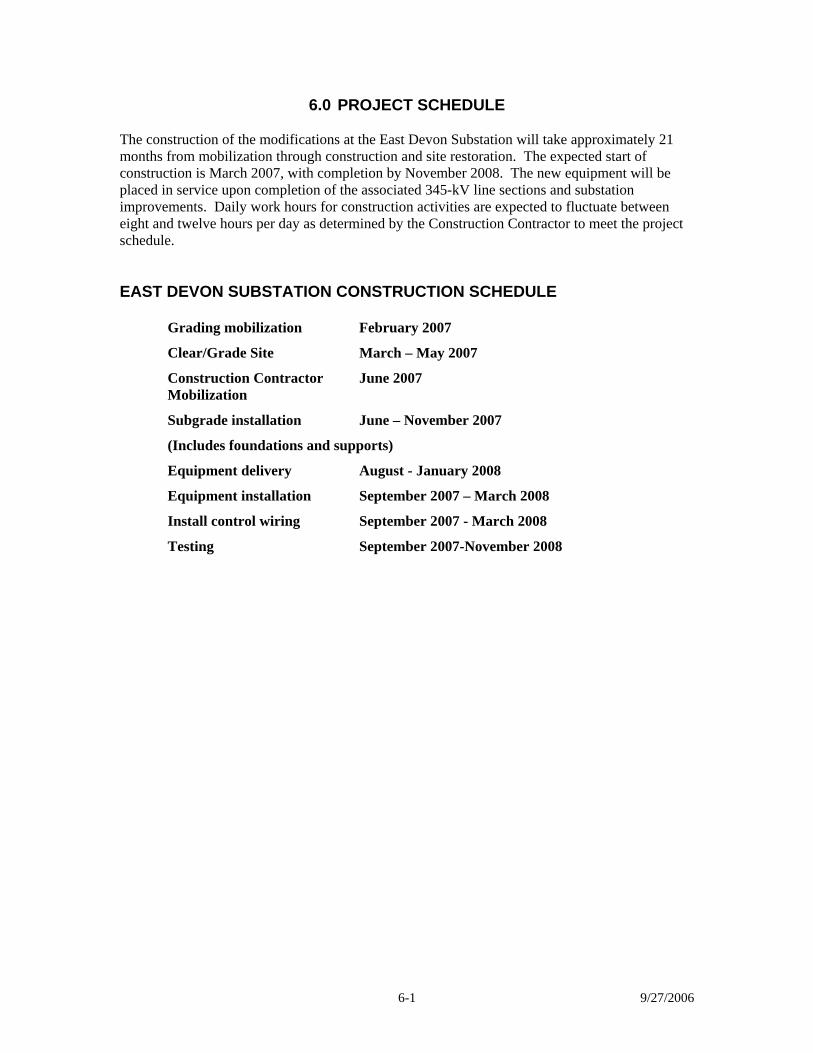
6.0 PROJECT SCHEDULE The construction of the modifications at the East Devon Substation will take approximately 21 months from mobilization through construction and site restoration. The expected start of construction is March 2007, with completion by November 2008. The new equipment will be placed in service upon completion of the associated 345-kV line sections and substation improvements. Daily work hours for construction activities are expected to fluctuate between eight and twelve hours per day as determined by the Construction Contractor to meet the project schedule. EAST DEVON SUBSTATION CONSTRUCTION SCHEDULE
Grading mobilization February 2007
Clear/Grade Site March – May 2007
Construction Contractor June 2007 Mobilization
Subgrade installation June – November 2007
(Includes foundations and supports)
Equipment delivery August - January 2008
Equipment installation September 2007 – March 2008
Install control wiring September 2007 - March 2008
Testing September 2007-November 2008
Middletown-Norwalk Project D&M Plan East Devon Substation
9/27/2006
APPENDICES
A Drawings B Docket No. 272 - Selected
Portions of Decision and Order C D&M Plan Change Approval
Process
Middletown-Norwalk Project D&M Plan East Devon Substation
9/27/2006
APPENDIX A
DRAWINGS
EXHIBIT 1 – Key Map EXHIBIT 2 – Aerial Photograph EXHIBIT 3 – General Arrangement Plan and Sections EXHIBIT 4 – Site Grading Plan EXHIBIT 5 – Site Grading Sections EXHIBIT 6 – Sedimentation and Erosion Control Plan EXHIBIT 7 – Sedimentation and Erosion Control Details EXHIBIT 8 – Landscape Plan
Middletown-Norwalk Project D&M Plan East Devon Substation
9/27/2006
APPENDIX B
DOCKET NO. 272 SELECTED PORTIONS OF DECISION AND ORDER
Middletown-Norwalk Project D&M Plan East Devon Substation
B-1 9/27/2006
APPENDIX B DOCKET 272
SELECTED PORTIONS OF DECISION AND ORDER
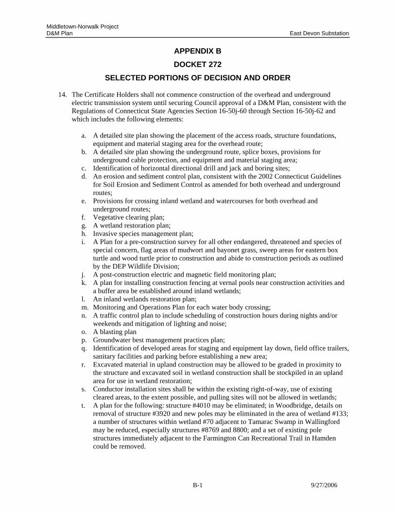
14. The Certificate Holders shall not commence construction of the overhead and underground electric transmission system until securing Council approval of a D&M Plan, consistent with the Regulations of Connecticut State Agencies Section 16-50j-60 through Section 16-50j-62 and which includes the following elements:
a. A detailed site plan showing the placement of the access roads, structure foundations,
equipment and material staging area for the overhead route; b. A detailed site plan showing the underground route, splice boxes, provisions for
underground cable protection, and equipment and material staging area; c. Identification of horizontal directional drill and jack and boring sites; d. An erosion and sediment control plan, consistent with the 2002 Connecticut Guidelines
for Soil Erosion and Sediment Control as amended for both overhead and underground routes;
e. Provisions for crossing inland wetland and watercourses for both overhead and underground routes;
f. Vegetative clearing plan; g. A wetland restoration plan; h. Invasive species management plan; i. A Plan for a pre-construction survey for all other endangered, threatened and species of
special concern, flag areas of mudwort and bayonet grass, sweep areas for eastern box turtle and wood turtle prior to construction and abide to construction periods as outlined by the DEP Wildlife Division;
j. A post-construction electric and magnetic field monitoring plan; k. A plan for installing construction fencing at vernal pools near construction activities and
a buffer area be established around inland wetlands; l. An inland wetlands restoration plan; m. Monitoring and Operations Plan for each water body crossing; n. A traffic control plan to include scheduling of construction hours during nights and/or
weekends and mitigation of lighting and noise; o. A blasting plan p. Groundwater best management practices plan; q. Identification of developed areas for staging and equipment lay down, field office trailers,
sanitary facilities and parking before establishing a new area; r. Excavated material in upland construction may be allowed to be graded in proximity to
the structure and excavated soil in wetland construction shall be stockpiled in an upland area for use in wetland restoration;
s. Conductor installation sites shall be within the existing right-of-way, use of existing cleared areas, to the extent possible, and pulling sites will not be allowed in wetlands;
t. A plan for the following: structure #4010 may be eliminated; in Woodbridge, details on removal of structure #3920 and new poles may be eliminated in the area of wetland #133; a number of structures within wetland #70 adjacent to Tamarac Swamp in Wallingford may be reduced, especially structures #8769 and 8800; and a set of existing pole structures immediately adjacent to the Farmington Can Recreational Trail in Hamden could be removed.
Middletown-Norwalk Project D&M Plan East Devon Substation
B-2 9/27/2006
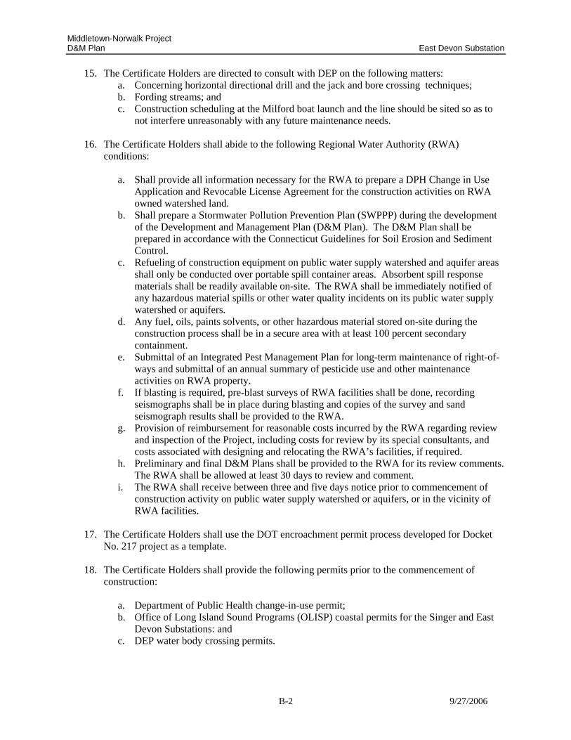
15. The Certificate Holders are directed to consult with DEP on the following matters: a. Concerning horizontal directional drill and the jack and bore crossing techniques; b. Fording streams; and c. Construction scheduling at the Milford boat launch and the line should be sited so as to
not interfere unreasonably with any future maintenance needs.
16. The Certificate Holders shall abide to the following Regional Water Authority (RWA) conditions:
a. Shall provide all information necessary for the RWA to prepare a DPH Change in Use Application and Revocable License Agreement for the construction activities on RWA owned watershed land.
b. Shall prepare a Stormwater Pollution Prevention Plan (SWPPP) during the development of the Development and Management Plan (D&M Plan). The D&M Plan shall be prepared in accordance with the Connecticut Guidelines for Soil Erosion and Sediment Control.
c. Refueling of construction equipment on public water supply watershed and aquifer areas shall only be conducted over portable spill container areas. Absorbent spill response materials shall be readily available on-site. The RWA shall be immediately notified of any hazardous material spills or other water quality incidents on its public water supply watershed or aquifers.
d. Any fuel, oils, paints solvents, or other hazardous material stored on-site during the construction process shall be in a secure area with at least 100 percent secondary containment.
e. Submittal of an Integrated Pest Management Plan for long-term maintenance of right-of-ways and submittal of an annual summary of pesticide use and other maintenance activities on RWA property.
f. If blasting is required, pre-blast surveys of RWA facilities shall be done, recording seismographs shall be in place during blasting and copies of the survey and sand seismograph results shall be provided to the RWA.
g. Provision of reimbursement for reasonable costs incurred by the RWA regarding review and inspection of the Project, including costs for review by its special consultants, and costs associated with designing and relocating the RWA’s facilities, if required.
h. Preliminary and final D&M Plans shall be provided to the RWA for its review comments. The RWA shall be allowed at least 30 days to review and comment.
i. The RWA shall receive between three and five days notice prior to commencement of construction activity on public water supply watershed or aquifers, or in the vicinity of RWA facilities.
17. The Certificate Holders shall use the DOT encroachment permit process developed for Docket
No. 217 project as a template.
18. The Certificate Holders shall provide the following permits prior to the commencement of construction:
a. Department of Public Health change-in-use permit; b. Office of Long Island Sound Programs (OLISP) coastal permits for the Singer and East
Devon Substations: and c. DEP water body crossing permits.
Middletown-Norwalk Project D&M Plan East Devon Substation
B-3 9/27/2006
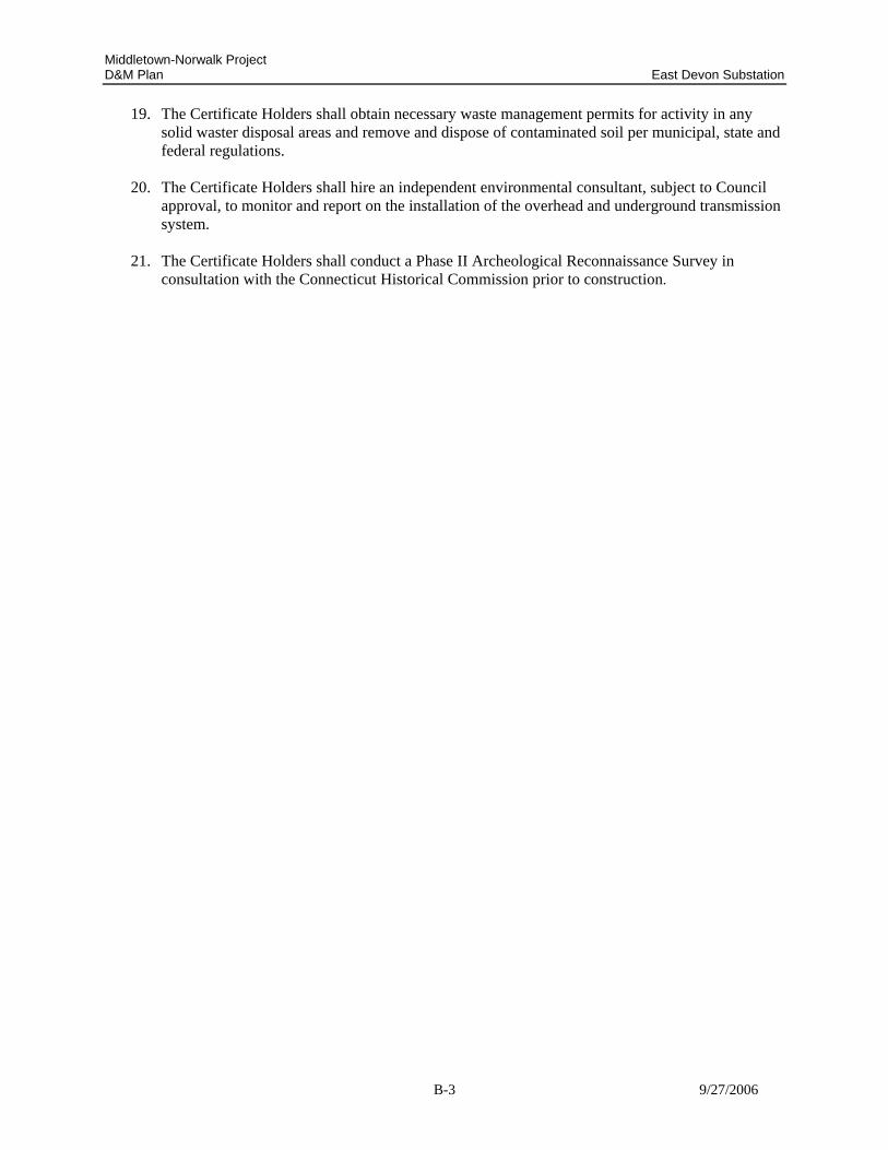
19. The Certificate Holders shall obtain necessary waste management permits for activity in any solid waster disposal areas and remove and dispose of contaminated soil per municipal, state and federal regulations.
20. The Certificate Holders shall hire an independent environmental consultant, subject to Council
approval, to monitor and report on the installation of the overhead and underground transmission system.
21. The Certificate Holders shall conduct a Phase II Archeological Reconnaissance Survey in
consultation with the Connecticut Historical Commission prior to construction.
Middletown-Norwalk Project D&M Plan East Devon Substation
9/27/2006
APPENDIX C
D&M PLAN CHANGE APPROVAL PROCESS
Middletown-Norwalk Project D&M Plan East Devon Substation
C-1 9/27/2006
APPENDIX C
D&M PLAN CHANGE APPROVAL PROCESS
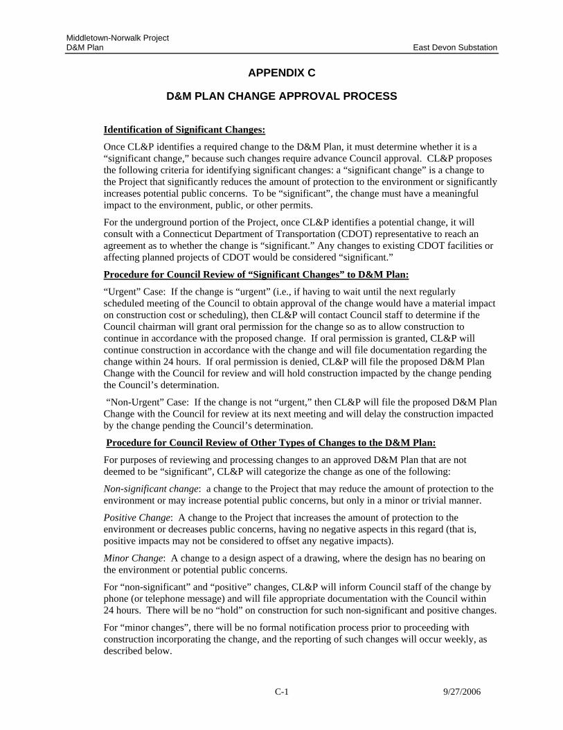
Identification of Significant Changes:
Once CL&P identifies a required change to the D&M Plan, it must determine whether it is a “significant change,” because such changes require advance Council approval. CL&P proposes the following criteria for identifying significant changes: a “significant change” is a change to the Project that significantly reduces the amount of protection to the environment or significantly increases potential public concerns. To be “significant”, the change must have a meaningful impact to the environment, public, or other permits.
For the underground portion of the Project, once CL&P identifies a potential change, it will consult with a Connecticut Department of Transportation (CDOT) representative to reach an agreement as to whether the change is “significant.” Any changes to existing CDOT facilities or affecting planned projects of CDOT would be considered “significant.”
Procedure for Council Review of “Significant Changes” to D&M Plan:
“Urgent” Case: If the change is “urgent” (i.e., if having to wait until the next regularly scheduled meeting of the Council to obtain approval of the change would have a material impact on construction cost or scheduling), then CL&P will contact Council staff to determine if the Council chairman will grant oral permission for the change so as to allow construction to continue in accordance with the proposed change. If oral permission is granted, CL&P will continue construction in accordance with the change and will file documentation regarding the change within 24 hours. If oral permission is denied, CL&P will file the proposed D&M Plan Change with the Council for review and will hold construction impacted by the change pending the Council’s determination.
“Non-Urgent” Case: If the change is not “urgent,” then CL&P will file the proposed D&M Plan Change with the Council for review at its next meeting and will delay the construction impacted by the change pending the Council’s determination.
Procedure for Council Review of Other Types of Changes to the D&M Plan:
For purposes of reviewing and processing changes to an approved D&M Plan that are not deemed to be “significant”, CL&P will categorize the change as one of the following:
Non-significant change: a change to the Project that may reduce the amount of protection to the environment or may increase potential public concerns, but only in a minor or trivial manner.
Positive Change: A change to the Project that increases the amount of protection to the environment or decreases public concerns, having no negative aspects in this regard (that is, positive impacts may not be considered to offset any negative impacts).
Minor Change: A change to a design aspect of a drawing, where the design has no bearing on the environment or potential public concerns.
For “non-significant” and “positive” changes, CL&P will inform Council staff of the change by phone (or telephone message) and will file appropriate documentation with the Council within 24 hours. There will be no “hold” on construction for such non-significant and positive changes.
For “minor changes”, there will be no formal notification process prior to proceeding with construction incorporating the change, and the reporting of such changes will occur weekly, as described below.
Middletown-Norwalk Project D&M Plan East Devon Substation
C-2 9/27/2006
Weekly Reporting of All Changes to D&M Plans
CL&P will document all D&M Plan changes - significant, non-significant, positive, and minor –in an attachment to the environmental inspector’s weekly report.
Middletown-Norwalk Project D&M Plan East Devon Substation
C-3 9/27/2006
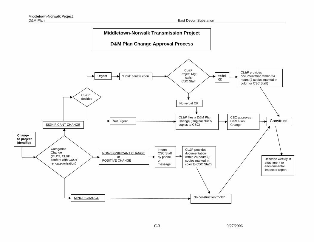
Categorize Change (If U/G, CL&P confers with CDOT re: categorization)
CL&P decides
SIGNIFICANT CHANGE
NON-SIGNIFICANT CHANGE or POSITIVE CHANGE
No construction “hold”
Change to project identified
MINOR CHANGE
“Hold” construction
CL&P files a D&M Plan Change (Original plus 5 copies to CSC)
CL&P Project Mgt
calls CSC Staff
CL&P provides documentation within 24 hours (2 copies marked in color for CSC Staff)
Verbal OK
No verbal OK
Construct CSC approves D&M Plan Change
Describe weekly in attachment to environmental inspector report
Urgent
Not urgent
Middletown-Norwalk Transmission Project
D&M Plan Change Approval Process
CL&P provides documentation within 24 hours (2 copies marked in color to CSC Staff)
Inform CSC Staff by phone or message