Embed Size (px)
Citation preview
Copyright © 2012 Tech Science Press CMC, vol.32, no.1, pp.61-79, 2012
Development of a Morphing Skin Based on theHoneycomb Reinforced Elastomer
C. Wang1, J.H. Qiu1,2, R. Nie1, H.L. Ji1 and W. Deng1
Abstract: The morphing skin has been a main obstacle in the real-world imple-mentation of morphing aircrafts. This paper presents a morphing skin made of theelastomer reinforced by the honeycomb structure. A matrix made from elastomerprovides possibilities to configure the morphing skin and the honeycomb structurewith smaller in-plane modulus and larger out-of-plane modulus is thought to besuitable to reinforce the elastomer. The polyurethane elastomer is selected and syn-thesized by the casting method with the prepolymer approach, after which a tensiletest is conducted to get its stress-strain relationship. To decrease the skin depth anddiminish the local deformation in the honeycomb cell, the elastomer is filled intothe honeycomb core rather than just working as the flexible face sheets, which leadsto the so-called honeycomb reinforced elastomer. To present its mechanical prop-erties finite element method is applied to analyze the morphing skin with a plug-inof commercial software Abaqus developed to model the skin in details. Differentgeometry and material parameters are taken into consideration with three kinds ofresults calculated namely, the equivalent tensile modulus, the non-dimensionalizedequivalent three-point bending stiffness and the linear strain capacity. After thesimulation analysis, samples of the morphing skins are fabricated by the compres-sion molds method and the tensile tests have verified both the concept and the sim-ulation results. At last, an optimization performed has shown a significant declineof the tensile modulus and out-of-plane displacement of the morphing skin.
Keywords: Morphing skin, Honeycomb, Elastomer, Simulation, Optimization
1 State Key Laboratory of Mechanics and Control for Mechanical Structures, College of AerospaceEngineering, Nanjing University of Aeronautics and Astronautics, Nanjing, China
2 Corresponding author: J.H Qiu, Address: College of Aerospace Engineering, Nanjing Univer-sity of Aeronautics and Astronautics, Yudao Street 29, Nanjing 210016, China. Tel.: +86-25-84891123; fax: +86-25-84891123. E-mail address: [email protected].

62 Copyright © 2012 Tech Science Press CMC, vol.32, no.1, pp.61-79, 2012
1 Introduction
The morphing technology makes an aircraft have the ability to change its geom-etry parameters during flight [Jha and Kudva (2004)]. Since wings are the mostinfluential parts of an aircraft, most of the designs are focused on the wings. Theconventional fixed shape aircraft can only have the best performance in the estab-lished missions and can’t adapt to the changed missions very well. Scientists andengineers have been interested in the field early from the Soviet Union telescopingwing demonstrator LIG-7 in the 1930s to the variable sweep wings appearing inthe 1940s and becoming prevalent in the next two decades. In the Mission Adap-tive Wing program (MAW) a smooth variable camber wing is installed onto theF-111 fighter making the demonstrator have the capability of changing the param-eters of both the wing planform and wing airfoil [Gilbert (1981)]. A hingelessmorphing leading and trailing edge with integral actuation mechanism based onthe shape memory alloy is developed in the Smart Wing Project with comparisonsto the trailing edge actuated by the conventional electric motors and piezoelectricmotors [Kudva (2004)]. The unmanned morphing aircraft MFX-1 under a programcalled “Next Generation Morphing Structures (N-MAS)” is capable of large geom-etry changes including 200% in the aspect ratio, 70% in the wing area and 40% inthe wing span [Bowman, Sanders, Cannon, Kudva, Joshi and Weisshaar (2007)].For the researchers who want to make aircrafts perform more efficiently at differentaltitudes and speeds, the morphing technology has always been a great aspiration.Even though the previous programs have achieved success to some extent, therestill remain many problems to be solved among which the morphing skin is a mainobstacle.
In general three basic requirements of a morphing skin can be summarized below.Firstly, the morphing skin should have a sufficient strain capacity which meanswhen the smart skin is deformed the skin material can’t be broken. This can bedescribed “be capable to morph”. Secondly, the energy cost to actuate the skinto morph should be low enough which requires a low equivalent modulus in themorphing direction. This can be called “be easy to morph”. Last but not least,the morphing skin should be able to carry the local aerodynamic loads and trans-mit the loads to the inner structure. The third requirement can be called “be safeto morph”. To meet the requirements above, two basic approaches can be made.One is by change of material stiffness, such as the shape memory polymer, and theother is by stiffness tailoring. Aeroelastic tailoring is used to control aeroelastic de-formation and affect the performance of the aircraft by embodying the directionalstiffness into an aircraft structure [Shirk, Hertz and Weisshaar (1986)] and by theapproach of stiffness tailoring different stiffness can be achieved in different di-rections, which is suitable for the design of morphing skins. Thill, Etches, Bond,

Development of a Morphing Skin 63
Potter and Weaver (2008; 2010) summarized the materials, structures and designsof morphing skins and made use of the composite corrugated structure in a morph-ing trailing edge, firstly by corrugated laminates and then by corrugated sandwichstructures to overcome its drawback of the low out-of-plane stiffness. Gandhi andAnusonti-Inthra (2008) identified the desirable attributes of a flexible skin espe-cially in the airfoil camber morphing and Olympio and Gandhi (2010a) presentedthe concept of the sandwich structure skin with a honeycomb core and two flexibleface sheets. Bubert, Woods, Kothera and Wereley (2010) demonstrated a flexiblematrix composites composed of elastomer and carbon fiber laminae which is sup-ported by a flexible honeycomb made of durable plastics.
This article aims to present a morphing skin made of the elastomeric material andthe directional reinforcement material, which is planned to be installed onto a mor-phing trailing edge mechanism. And the morphing skin is hoped to be stretchedand compressed in one dimension with the max equivalent strain less than 5%. Thefollowing will describe first the conceptual development of the honeycomb rein-forced elastomer, then the parametric study by numerical simulation in the finiteelement software Abaqus, together with the fabrication and the sample test. At lastan optimization is performed to get better performance for a real-world implemen-tation.
2 Conceptual development
Since the strain capacity is required, a matrix made from elastomer provides possi-bilities to configure the morphing skin. While a morphing skin purely made fromelastomer material is too flexible to carry the aerodynamic loads, some kind ofreinforcement material will be needed to stiffen the skin in the proper direction.The low stiffness in the morphing direction should be compensated by the highstiffness in the non-morphing direction to diminish the overall aerodynamic defor-mation, which means the morphing skin would be anisotropic. The honeycombstructure with relatively smaller in-plane modulus and larger out-of-plane modulusis thought to be suitable for the applications of the morphing skin. The in-planesketch of a honeycomb cell can be described by the geometric parameters shownin Fig. 1, in which h is the vertical wall length, l is the inclined wall length, t isthe honeycomb thickness and θ is the cell angle (counterclockwise rotation fromx axis to the inclined wall represents positive value). The ratio of the thickness tothe length t/l (the vertical wall has the same length to the inclined wall) is thoughtto represent the relative density of the structure. According to Gibson and Ashby’sresearch (1997), the out-of-plane equivalent modulus is proportional to the hon-eycomb relative density and its in-plane equivalent modulus is proportional to thecube of it, both of which are influenced by the geometric parameters of the honey-

64 Copyright © 2012 Tech Science Press CMC, vol.32, no.1, pp.61-79, 2012
comb cell and the honeycomb material parameter, making the honeycomb structurehave a larger out-of-plane modulus than the in-plane modulus.
50 60 40
30 20 10
0
Figure 1: (a) The in-plane sketch of the honeycomb cell, (b) Cell shapes of thehoneycomb
In the usual applications, the honeycomb is used as the core of the sandwich struc-ture, carrying the shear load, stabilizing the face sheets [Mackerle (2002)]. Whilein the morphing skin proposed by Olympio and Gandhi (2010a) the modulus of theface sheet is quite low compared to those face sheets used in the ordinary honey-comb sandwich structures and the effects of the flexible face sheets on the bendingstiffness can be neglected which is just needed to carry aerodynamic loads. As theside effect, the flexibility of face sheets will cause a larger depth of the morph-ing skin which means the increase of the weight and decrease of the inner space.The adhesion force between the core and the face sheets is small and aerodynamicloads may cause local deformations in the honeycomb cell especially as it has aconsiderable wall length.
A simple and direct method to make a good “trade-off” may be to fill the honey-comb core with the elastomer so the elastomer will be adhered to the honeycombcell walls, thus the adhesion between the elastomer and the honeycomb will beenhanced substantially, eliminating the local deformation. Meanwhile, the elas-tomer filled in the honeycomb will increase the bending stiffness, which in turnwill reduce the depth to get the same bending stiffness. In a viewpoint of manufac-turing, a morphing skin based on the honeycomb core filled with elastomer couldbe easier to be fabricated compared to the morphing skin with the honeycomb coreadhered to flexible face sheets, where the adhesive layer is necessary and mightbe broken under cyclic morphing. Thus, in this design the elastomer will be theflexible matrix and the honeycomb structure is used to reinforce it, which leads to
Development of a Morphing Skin 65
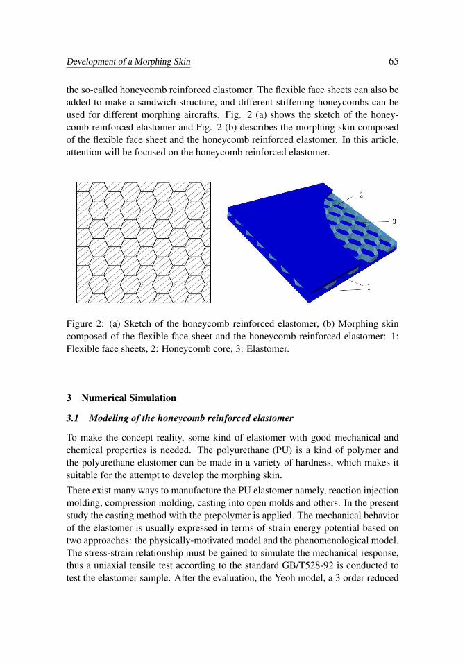
the so-called honeycomb reinforced elastomer. The flexible face sheets can also beadded to make a sandwich structure, and different stiffening honeycombs can beused for different morphing aircrafts. Fig. 2 (a) shows the sketch of the honey-comb reinforced elastomer and Fig. 2 (b) describes the morphing skin composedof the flexible face sheet and the honeycomb reinforced elastomer. In this article,attention will be focused on the honeycomb reinforced elastomer.
Figure 2: (a) Sketch of the honeycomb reinforced elastomer, (b) Morphing skincomposed of the flexible face sheet and the honeycomb reinforced elastomer: 1:Flexible face sheets, 2: Honeycomb core, 3: Elastomer.
3 Numerical Simulation
3.1 Modeling of the honeycomb reinforced elastomer
To make the concept reality, some kind of elastomer with good mechanical andchemical properties is needed. The polyurethane (PU) is a kind of polymer andthe polyurethane elastomer can be made in a variety of hardness, which makes itsuitable for the attempt to develop the morphing skin.
There exist many ways to manufacture the PU elastomer namely, reaction injectionmolding, compression molding, casting into open molds and others. In the presentstudy the casting method with the prepolymer is applied. The mechanical behaviorof the elastomer is usually expressed in terms of strain energy potential based ontwo approaches: the physically-motivated model and the phenomenological model.The stress-strain relationship must be gained to simulate the mechanical response,thus a uniaxial tensile test according to the standard GB/T528-92 is conducted totest the elastomer sample. After the evaluation, the Yeoh model, a 3 order reduced

66 Copyright © 2012 Tech Science Press CMC, vol.32, no.1, pp.61-79, 2012
polynomial model, is selected to express the mechanical behavior of the elastomer.The nominal stress-strain relationship of the polyurethane elastomer is depicted inFig. 3 from which one can conclude that PU elastomer has the hyperelastic propertyand in the medium morphing capacity focused by this article the elastomer can beseen as linear with a tangent modulus of about 8 MPa.
Figure 3: Nominal stress-strain relationship of the PU elastomer
Figure 4: Plug-in interface and the finite element model
The honeycomb reinforced elastomer can be seen orthotropic whose constitutivelaw is written through the compliance matrix with the engineering constants: Young’sModulus: E1, E2, E3, shear modulus: G12, G13, G23 and Poisson ratio: ν12, ν13, ν23with the subscripts “1, 2, 3” pointing at x, y and z direction. Taking the nonlinear

Development of a Morphing Skin 67
properties of the elastomer into consideration, a more sophisticated expression canbe written to express the stress-strain relationship with the superscript “s” added torepresent the equivalent value in every small increment.
dε1dε2dε3dε4dε5dε6
=
1Es
1−υs
12Es
2−υs
13Es
30 0 0
−υs21
Es1
1Es
2−υs
23Es
30 0 0
−υs31
Es1−υs
32Es
2
1Es
30 0 0
0 0 0 1Gs
230 0
0 0 0 0 1Gs
310
0 0 0 0 0 1Gs
12
dσ1dσ2dσ3dσ4dσ5dσ6
(1)
The morphing direction is defined in x direction. To evaluate the morphing skin,some parameters should be selected. The first is the strain capacity in the morphingdirection, which can be found by determining the max stress in the morphing skin.The second is the equivalent modulus in the morphing direction. By seeing themorphing skin as a homogeneous material, the equivalent mechanical propertiesare calculated. The displacement loads are imposed at one end of the model whilefixing the opposite. The imposed displacement represents the equivalent strain andthe reaction forces at the imposed nodes are summarized to calculate the equivalentstress. And the value of equivalent tensile modulus is calculated by the expressionbelow.
Ei =dσi
dεi= ∑(RF)i/S
∆Li/L(2)
Here, ∑ (RF)i is the reaction force, S and L are the area of the cross section and thelength of the model respectively.
The third parameter is the equivalent bending stiffness Bi. The three-point bend-ing test is usually applied to test the bending performance of a single plate. Andto present the results more intuitively, the stiffness values are non-dimensionalizedwith respect to the 0.5 mm thick three-point bending-stiffness of the Al sheet skinwith the same span and width to the morphing skin models. The three-point bend-ing stiffness is calculated according to the expression below.
Bi =∆P∆ f
= EY4bH3
Sl(3)
And, the components ∆P and ∆ f mean the increment of the load and the deflection.The components Sl , b and H represent the span, the width and depth of the model.The component EY represents the effect of material property. The honeycomb re-inforced elastomer is modeled in details, and the similar computational approach
68 Copyright © 2012 Tech Science Press CMC, vol.32, no.1, pp.61-79, 2012
was presented by Chamis and Aiello (1988) to determine the equivalent mechan-ical and thermal properties of the metallic honeycomb core. The honeycomb andelastomer are modeled separately, then assembled and merged into one part withtheir original properties retained which indicates bonding between the honeycombcell walls and the elastomer is thought to be perfect. The honeycomb structure ismodeled by the shell element S4R and the hybrid elements C3D8H and C3D6Hare used to model the elastomer. As to the material property, the honeycomb corematerial is idealized as bilinear [Papka and Kyriakides (1988)] and the elastomermaterial is thought to be hyperelastic, expressed by the Yeoh model selected. Aplug-in based on Python language is developed for convenience and further studywith which the finite element models generated can vary with input of the geometryand material parameters. Fig. 4 shows the plug-in interface and the finite elementmodel generated.
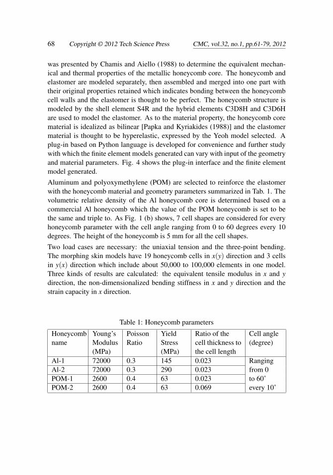
Aluminum and polyoxymethylene (POM) are selected to reinforce the elastomerwith the honeycomb material and geometry parameters summarized in Tab. 1. Thevolumetric relative density of the Al honeycomb core is determined based on acommercial Al honeycomb which the value of the POM honeycomb is set to bethe same and triple to. As Fig. 1 (b) shows, 7 cell shapes are considered for everyhoneycomb parameter with the cell angle ranging from 0 to 60 degrees every 10degrees. The height of the honeycomb is 5 mm for all the cell shapes.
Two load cases are necessary: the uniaxial tension and the three-point bending.The morphing skin models have 19 honeycomb cells in x(y) direction and 3 cellsin y(x) direction which include about 50,000 to 100,000 elements in one model.Three kinds of results are calculated: the equivalent tensile modulus in x and ydirection, the non-dimensionalized bending stiffness in x and y direction and thestrain capacity in x direction.
Table 1: Honeycomb parameters
Honeycombname
Young’sModulus(MPa)
PoissonRatio
YieldStress(MPa)
Ratio of thecell thickness tothe cell length
Cell angle(degree)
Al-1 72000 0.3 145 0.023 RangingAl-2 72000 0.3 290 0.023 from 0POM-1 2600 0.4 63 0.023 to 60˚POM-2 2600 0.4 63 0.069 every 10˚

Development of a Morphing Skin 69
Figure 5: Linear strain capacity in x direction
3.2 Simulation Results
The linear strain capacity is calculated by determining whether the max stress ofthe morphing skin material has been beyond the yield stress, thus the honeycombcore material will be linearly elastic and elastomer material can also be thought tobe linear since the capacity value is relatively much lower compared to the totalstrain capacity of elastomer gained from the test. As Fig. 5 shows the linear straincapacity will increase with the cell angle and a larger ratio of the yield stress to theYoung’s modulus of the honeycomb material will cause a larger linear strain capac-ity but the opposite results will be caused by the increase of the relative density ofthe honeycomb core.
As Fig. 6 and Fig. 7 show, the tensile modulus will be influenced by the cell angleand the honeycomb reinforced elastomer shows the anisotropic property. The largertensile modulus in x (y) direction corresponds to the smaller one in y (x) direction.The regular hexagon honeycomb whose cell angle is 30 degrees is the critical in-stance where the tensile modulus in x and y directions are similar. Furthermore,comparing the modulus with different honeycomb parameters but the same cell an-gle, one can include that a larger honeycomb material Young’s modulus and a largerrelative density of the honeycomb core will lead to a larger equivalent modulus ofthe overall skin. Indeed, the equivalent tensile modulus can be as low as 10-20 MPaif proper geometry and material parameters are selected.
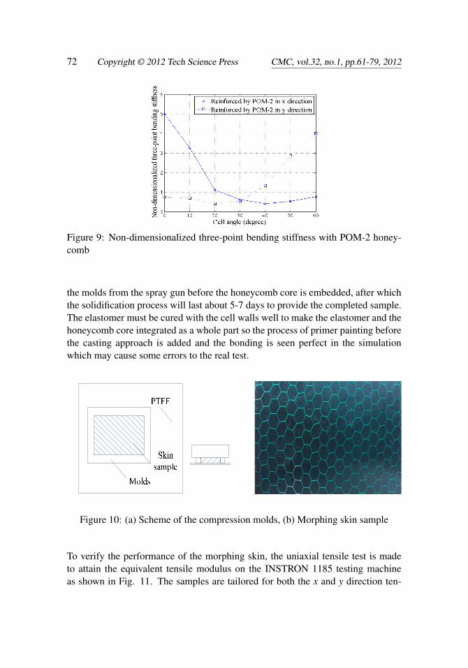
The relationships between the non-dimensionalized three-point bending stiffnessand the cell angle are depicted in Fig. 8 and Fig. 9. While the trend is similar to thetensile modulus, what is important is the ability to carry aerodynamic loads. The

70 Copyright © 2012 Tech Science Press CMC, vol.32, no.1, pp.61-79, 2012
Figure 6: Equivalent tensile modulus of the elastomer reinforced by: (a) Al, (b)POM-1
Figure 7: Equivalent tensile modulus of the elastomer reinforced by POM-2

Development of a Morphing Skin 71
Figure 8: Non-dimensionalized three-point bending stiffness with: (a) Al, (b)POM-1 honeycomb
morphing skin models can reach 0.47 mm thick Al sheet model in x direction and1.16 mm thick Al sheet model in y direction when the tensile modulus is as low as10-20 MPa in x direction. The larger honeycomb material Young’s modulus andrelative density will come with the larger bending stiffness.
The results have indicated that by selecting the proper material and geometry prop-erties the tensile modulus in the morphing direction can be reduced to a limitedvalue with a much larger tensile modulus and bending stiffness in the other direc-tion increasing the overall capability to carry aerodynamic loads. And a mediumstrain capacity requirement such as the morphing trailing edge can be satisfied withthis skin concept.
4 Fabrication of the morphing skin and the sample test
After the simulation analysis, two kinds of samples are fabricated: one is the PUelastomer reinforced by the metallic regular hexagon honeycomb which has thesame parameters to the simulation model Al-2, the other is reinforced by the POMhoneycomb whose cell angle is 60 degrees. The POM honeycomb core is carvedand cut by the laser thus the cell wall thickness is increased for convenience ofmanufacturing which leads to the increase of the cell wall length to keep the relativedensity unchanged. The skin samples are fabricated by the casting method and tocontrol the depth of the elastomer the compression molds approach is applied asdepicted in Fig. 10. The polytetrafluoroethylene (PTFE) film is used to preventthe bonding between the elastomer and molds. The elastomer is firstly casted into
72 Copyright © 2012 Tech Science Press CMC, vol.32, no.1, pp.61-79, 2012
Figure 9: Non-dimensionalized three-point bending stiffness with POM-2 honey-comb
the molds from the spray gun before the honeycomb core is embedded, after whichthe solidification process will last about 5-7 days to provide the completed sample.The elastomer must be cured with the cell walls well to make the elastomer and thehoneycomb core integrated as a whole part so the process of primer painting beforethe casting approach is added and the bonding is seen perfect in the simulationwhich may cause some errors to the real test.
Figure 10: (a) Scheme of the compression molds, (b) Morphing skin sample
To verify the performance of the morphing skin, the uniaxial tensile test is madeto attain the equivalent tensile modulus on the INSTRON 1185 testing machineas shown in Fig. 11. The samples are tailored for both the x and y direction ten-

Development of a Morphing Skin 73
sile test. Since no standards exist for the morphing skin test, the test condition isselected according to some similar standards. Tab. 2 summarizes the sample pa-rameters and for the POM samples the ratio of the cell thickness to the cell lengthis not absolutely the same to the simulation model POM-2 because of the laser cau-terization, thus their simulation results are re-calculated. The test results comparedto the simulation results are summarized in Tab. 3, from which one can concludethere exist some errors between the finite element model and the real morphingskin sample that may be caused by the simulation process, the material propertiesinput of which the elastomer properties may be influenced by the random of thehandmade casting process. But in any case the tests have proved that the 30 degreeinstance is critical with the similar tensile modulus in x and y direction and the 60degree instance will no doubt lead to an anisotropic property of the in-plane tensilemodulus with one order of magnitude between x and y direction.
Figure 11: (a) Test samples, (b) Tensile test
Table 2: Morphing skin sample parameters
Sample name Honeycomb Ratio of the cell thickness Tensilematerial to the length (t/l) direction
Sample-Al-x Al 0.023 xSample-Al-y Al 0.023 ySample-POM-x POM 0.073 xSample-POM-y POM 0.073 y

74 Copyright © 2012 Tech Science Press CMC, vol.32, no.1, pp.61-79, 2012
Table 3: Test results compared to the simulation
Sample name Test result Simulation result Relative error(MPa) (MPa)
Sample-Al-x 19.14 20.22 5.64%Sample-Al-y 15.58 17.48 12%Sample-POM-x 18.33 17.75 3.16%Sample-POM-y 172.58 145.99 15.41%
5 Optimization
The anisotropic property of the morphing skin has been verified by the parametricstudy and preliminary test in the above work. But for a real-world implementa-tion, the morphing skins are required to be installed onto the morphing trailingedge as panels, which will lead all the skin boundaries to be fixed and (or) pinned,increasing the overall tensile modulus [Olympio and Gandhi (2010b)]. The contra-dictory requirements should be handled properly with proper parameters selected.Thus, the optimization procedure below is necessary to obtain better design param-eters. An optimization was performed by Murugan, Saavedra Flores, Adhikari andFriswell (2012) to find the optimal fiber distribution for the fiber reinforced elas-tomer and the genetic algorithm was used to minimize the maximum out-of-planedisplacement and maximize the in-plane displacement of the morphing skin panel.
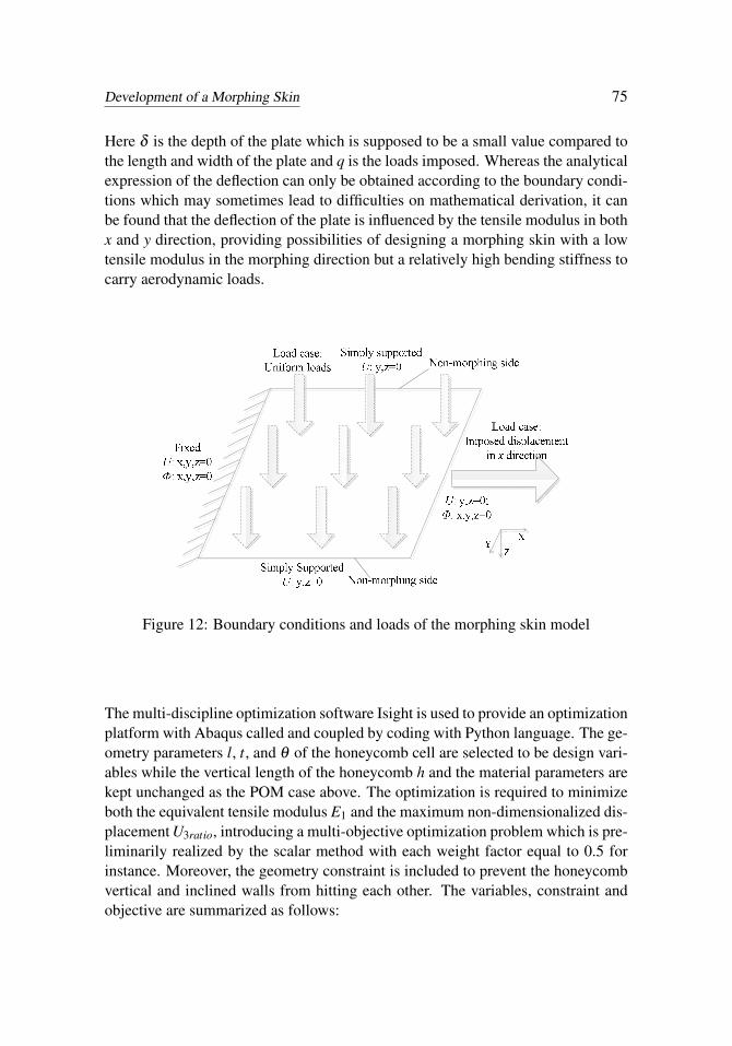
To optimize the honeycomb reinforced elastomer, the finite element models areregenerated to provide morphing skins with 11 honeycomb cells in x and y directioneach. Also two load cases are considered to calculate the equivalent tensile modulusE1 and the maximum out-of-plane displacement U3ratio caused by uniform loadsand non-dimensionalized by the 0.5 mm thick Al sheet. The skin models are simplysupported on the non-morphing sides and fixed on the other sides as depicted in Fig.12.
Furthermore the small deflection w of an anisotropic thin plate can be derived fromthe following differential equation [Timoshenko and Woinowsky-Krieger (1959)]:
D1∂ 4w∂x4 +D2
∂ 4w∂y4 +2D3
∂ 4w∂x2∂y2 = q (4)
In which:
D1 =E1δ 3
12(1−υ21υ12)D2 =
E2δ 3
12(1−υ21υ12)D3 = υ12D1 +2Dk Dk =
G12δ 3
12(5)
Development of a Morphing Skin 75
Here δ is the depth of the plate which is supposed to be a small value compared tothe length and width of the plate and q is the loads imposed. Whereas the analyticalexpression of the deflection can only be obtained according to the boundary condi-tions which may sometimes lead to difficulties on mathematical derivation, it canbe found that the deflection of the plate is influenced by the tensile modulus in bothx and y direction, providing possibilities of designing a morphing skin with a lowtensile modulus in the morphing direction but a relatively high bending stiffness tocarry aerodynamic loads.
Figure 12: Boundary conditions and loads of the morphing skin model
The multi-discipline optimization software Isight is used to provide an optimizationplatform with Abaqus called and coupled by coding with Python language. The ge-ometry parameters l, t, and θ of the honeycomb cell are selected to be design vari-ables while the vertical length of the honeycomb h and the material parameters arekept unchanged as the POM case above. The optimization is required to minimizeboth the equivalent tensile modulus E1 and the maximum non-dimensionalized dis-placement U3ratio, introducing a multi-objective optimization problem which is pre-liminarily realized by the scalar method with each weight factor equal to 0.5 forinstance. Moreover, the geometry constraint is included to prevent the honeycombvertical and inclined walls from hitting each other. The variables, constraint andobjective are summarized as follows:

76 Copyright © 2012 Tech Science Press CMC, vol.32, no.1, pp.61-79, 2012
Variables:l 1.732 < l < 5.196 (mm)θ −90◦ < θ < 90◦
t t ∈ {0.04, 0.08, 0.12}(mm)
(6)
Constraint:
h+2l sinθ > 0 (7)
Objective:
minw1E1 +w2U3ratio (8)
Here, wi (i=1, 2) is the weight factor of each single objective. The multi-islandgenetic algorithm (MIGA) is a kind of distributed genetic algorithm whose pop-ulation is divided into several smaller ones known as subpopulation in an islandwhere the traditional genetic algorithm is performed separately. Information ex-change among subpopulations is performed by moving some individuals from onesubpopulation to another known as migration. Diversity can be preserved whichmay help to gain better optimization results by adopting the approach [Cantú-Paz(1998); Miki (1999)]. In this case, there are 10 generations and 5 islands with eachsubpopulation size equal to 10. The optimization process is described in Fig. 13.
The optimal results are summarized in Tab. 4 compared to the starting designpoint, showing the significant decline of the in-plane tensile modulus and the non-dimensionalized out-of-plane displacement. Further study can be done by changingthe honeycomb geometry to a higher extent, making use of more proper materialand applying a more suitable algorithm and agent model to get better results withless simulation time.
Table 4: Optimum design point compared to the starting one
Parameter name l(mm) t(mm) θ (degree) E1(MPa) U3ratio
Starting design point 3.464 0.08 60.0 23.3 4.08Optimum design point 4.746 0.04 45.521 18.92 2.73
6 Conclusions
In this paper to meet the diverse requirements the morphing skin based on the hon-eycomb reinforced elastomer is designed to be anisotropic with a low stiffness in

Development of a Morphing Skin 77
Figure 13: Optimization process of the morphing skin
the morphing direction and a high stiffness in the non-morphing direction. Theequivalent mechanical properties of the morphing skin are influenced by the ge-ometry parameters and material properties. The equivalent tensile modulus can beas low as 10-20 MPa in the morphing direction which can be one order of mag-nitude lower than that in the non-morphing direction and the equivalent bendingstiffness has the similar trend that can reach the 0.5 mm to 1 mm thick Al sheetif proper parameters are selected. The linear strain capacity is also calculated inwhich the skin material can be seen linearly elastic, showing the adequate valuefor the morphing trailing edge application. Both the numerical simulation and thesample test have verified the honeycomb reinforced elastomer concept preliminar-ily. The optimization procedure is performed whose results have shown a signif-icant performance improvement, which in turn indicates the application potentialof the morphing skin. More attention can be devoted to better fabrication processand more proper optimization method with less calculation time, all of which is tomake the morphing skin together with the morphing aircraft gradually become areal-world implementation.
Acknowledgement: The research is supported by the National Natural ScienceFoundation of China under Grant No.50830201, Program for Changjiang Scholars

78 Copyright © 2012 Tech Science Press CMC, vol.32, no.1, pp.61-79, 2012
and Innovative Research Team in University (PCSIRT) (NO.IRT0968), the PriorityAcademic Program Development of Jiangsu Higher Education Institutions and alsosupported by the Foundation of Graduate Innovation Center in NUAA (kfjj120102)and the Fundamental Research Funds for the Central Universities.
Reference
Bowman, J.; Sanders, B.; Cannon, B.; Kudva, J.; Joshi, S.; Weisshaar, T.(2007): Development of Next Generation Morphing Aircraft Structures. Proceed-ings of 48th AIAA/ASME/ASCE/AHS/ASC Structures, Structural Dynamics, andMaterials Conference. United States.
Bubert, E.A.; Woods, B.; Kothera, C.; Wereley, N. (2010): Design and Fab-rication of a Passive 1D Morphing Aircraft Skin. Journal of Intelligent MaterialSystems and Structures, vol. 21, pp. 1699-1717.
Cantú-Paz, E. (1998): A Survey on Parallel Genetic Algorithms. CalculateursParallèles, Reseaux et Systems Repartis, vol. 10, pp. 141–171.
Chamis, C.C.; Aiello, R.A.; Murthy, P.L.N. (1988): Fiber Composite SandwichThermostructural Behavior: Computational Simulation. Journal of CompositesTechnology and Research, vol. 10, pp. 93-9.
Gandhi, F.; Anusonti-Inthra, P. (2008): Skin Design Studies for Variable CamberMorphing Airfoils. Smart Materials and Structures, vol. 17, doi. 10.1088/0964-1726/17/01/015025.
Gibson, L.; Ashby, M. (1997): Cellular Solids, Structures and Properties, 2ndedition. Cambridge University Press.
Gilbert, W.W. (1981): Mission Adaptive Wing System for Tactical Aircraft. Jour-nal of Aircraft, vol. 18, pp. 597-602.
Jha, A.K.; Kudva, J.N. (2004): Morphing Aircraft Concepts, Classifications, andChallenges. Proceedings of SPIE Smart Structures and Materials: Industrial andCommercial Applications of Smart Structures Technologies, vol. 5388, pp. 213-224.
Kudva, J.N. (2004): Overview of the DARPA Smart Wing Project. Journal ofIntelligent Material Systems and Structures, vol. 15, pp. 261-267.
Mackerle, J. (2002): Finite Element Analyses of Sandwich Structures: A Bibliog-raphy (1980–2001). Engineering Computations, vol. 19, pp. 206-245.
Miki, M.; Hiroyasu, T.; Kaneko, M.; Hatanaka, K. (1999): A Parallel GeneticAlgorithm with Distributed Environment Scheme. Proceedings of IEEE Interna-tional Conference on Systems, Man, and Cybernetics, vol. 1, pp. 695-700.
Murugan, S.; Saavedra Flores, E.I.; Adhikari, S.; Friswell, M.I. (2012): Op-

Development of a Morphing Skin 79
timal Design of Variable Fiber Spacing Composites for Morphing Aircraft Skins.Composite Structures, vol. 94, pp. 1626-1633.
Olympio, K.R.; Gandhi, F. (2010a): Flexible Skins for Morphing Aircraft UsingCellular Honeycomb Cores. Journal of Intelligent Material Systems and Structures,vol. 21, pp. 1719-1735.
Olympio, K.R.; Gandhi, F. (2010b): Zero Poisson’s Ratio Cellular Honeycombfor Flex Skins Undergoing One-Dimensional Morphing. Journal of Intelligent Ma-terial Systems and Structures, vol.21, pp. 1737-1753.
Papka, S.D.; Kyriakides, S. (1998): Experiments and Full-Scale Numerical Sim-ulations of In-plane Crushing of a Honeycomb. Acta Materialia, vol. 46, pp. 2765-2776.
Shirk, M.H.; Hertz, T.J.; Weisshaar, T.A. (1986): Aeroelastic Tailoring—Theory,Practice, and Promise. Journal of Aircraft, vol. 23, pp. 6-18.
Thill, C.; Etches, J.; Bond, I.; Potter, K.; Weaver, P. (2008): Morphing Skins.Aeronautical Journal, vol. 112, pp. 117-139.
Thill, C.; Etches, J.A.; Bond, I.P.; Potter, K.D.; Weaver, P.M. (2010): Compos-ite Corrugated Structures for Morphing Wing Skin Applications. Smart Materialsand Structures, vol. 19, doi. 10.1088/0964-1726/19/12/124009.
Timoshenko, S.; Woinowsky-Krieger, S. (1959): Theory of Plates and Shells,2nd edition. McGraw Hill Book Company.