Embed Size (px)
Citation preview

UNIVERSITAT ROVIRA I VIRGILI DEVELOPMENT OF A NOVEL CATALYTIC MEMBRANE REACTOR: APPLICATION IN WASTEWATER TREATMENT Oscar Antonio Osegueda Chicas Depósito legal:
Doctoral Thesis
Development of a novel catalytic membrane reactor:
Application in wastewater treatment
Oscar Antonio Osegueda Chicas
Tarragona, 2013


UNIVERSITAT ROVIRA I VIRGILI DEVELOPMENT OF A NOVEL CATALYTIC MEMBRANE REACTOR: APPLICATION IN WASTEWATER TREATMENT Oscar Antonio Osegueda Chicas Depósito legal:
Oscar Antonio Osegueda Chicas
Development of a novel catalytic membrane reactor:
Application in wastewater treatment
Doctoral thesis
Supervised by:
Prof. Dr. Francisco Medina
Dr. Anton Dafinov
Prof. Dr. Jesús Sueiras
Department of Chemical Engineering
Tarragona, 2013


UNIVERSITAT ROVIRA I VIRGILI DEVELOPMENT OF A NOVEL CATALYTIC MEMBRANE REACTOR: APPLICATION IN WASTEWATER TREATMENT Oscar Antonio Osegueda Chicas Depósito legal:

UNIVERSITAT ROVIRA I VIRGILI DEVELOPMENT OF A NOVEL CATALYTIC MEMBRANE REACTOR: APPLICATION IN WASTEWATER TREATMENT Oscar Antonio Osegueda Chicas Depósito legal:
i

UNIVERSITAT ROVIRA I VIRGILI DEVELOPMENT OF A NOVEL CATALYTIC MEMBRANE REACTOR: APPLICATION IN WASTEWATER TREATMENT Oscar Antonio Osegueda Chicas Depósito legal:
i
SUMMARY
There is an increasing concern about the quality and quantity of the
freshwater and groundwater resources for life supporting and environmental
needs. Mainly the increasing number of discharged pollutants that have
toxic and/or recalcitrant character (e.g., newly emerging problem pollutants,
heavy metals, pharmaceuticals etc.) requires stricter prescriptive limits for
pollutant concentrations. Chemical oxidation processes are usually preferred
among the others approaches due to their versatility and relatively fast
destruction of contaminants. Advanced oxidation processes (AOP) are
highly suitable when dealing with clean up of wastewaters and industrial
effluents, which are often loaded with different types of recalcitrant
pollutants. AOPs are based on generation of highly reactive oxygen species
such as hydroxyl radicals (•OH) which can effectively attack a wide range
of organic compounds. Even though this technique is considered as
powerful regarding contaminant degradation, it faces several practical
limitations in a large scale. Thus, the aim of this study was to propose and
test a novel strategy in order to extend the applicability of AOP, whereby
the integration of catalytic membrane reactors (CMRs) plays a key role.
Herein, various CMRs were prepared starting from commercial
ultrafiltration and microfiltration ceramic hollow fibers. These hollow fibers
are made of α-Al2O3 with an exceptional mechanical and chemical
resistance. Metallic palladium Pd was loaded (deposited) onto the CMRs as
a principal catalytic active phase in order to generate H2O2 using gaseous H2
and O2.
The hollow fibers were modified by two different procedures. The first
protocol was carried out using an incipient wetness technique. Two types of
membrane reactors were prepared: i) monometallic Pd membrane reactors

UNIVERSITAT ROVIRA I VIRGILI DEVELOPMENT OF A NOVEL CATALYTIC MEMBRANE REACTOR: APPLICATION IN WASTEWATER TREATMENT Oscar Antonio Osegueda Chicas Depósito legal:
ii
and ii) mixed double active phases membrane reactors, which are made of
metallic Pd and transitional metal oxide. The second protocol is a novel
procedure for preparing CMRs. This protocol is based on the sputtering
technique, and it was developed to reduce the amount of palladium as well
as to disperse it finely in the reaction zone. In fact the amount of Pd was
reduced up to 200 times compared with the first protocol. As well, the noble
metal was highly dispersed which leads to the formation of nanometer-sized
particles.
The physicochemical properties of the prepared CMRs were studied with
scanning electronic microscopy (SEM), environmental scanning electronic
microscopy (ESEM), micro X-ray diffraction (μ-XRD), N2-physisorption,
H2-chemisorption, X-ray photoelectron spectroscopy (XPS).
The monometallic Pd membrane reactors were tested in the oxidation of
phenol using in-situ generated H2O2. Several parameters have been
thoroughly evaluated including: i) efficiency of hydrogen conversion to
hydrogen peroxide, ii) efficiency in the use of H2O2 for phenol oxidation,
iii) reaction temperature, iv) intermediate products of the phenol oxidation,
v) the phenol conversion, and vi) total organic carbon (TOC) conversion as
well as the chemical oxygen demand (COD). The efficiency of hydrogen
involved in the H2O2 formation reaction was determined in all cases with
respect to the formation rate and the maximum achievable H2O2
concentration. The results clearly showed that the CMRs containing
monometallic Pd have high catalytic activity towards H2O2 generation,
where the size of metallic Pd appears to play a key role. However, when the
Pd-loaded CMRs were tested for the oxidation of phenol, no significant
degradation of the organic substrate was monitored. In other words, a

UNIVERSITAT ROVIRA I VIRGILI DEVELOPMENT OF A NOVEL CATALYTIC MEMBRANE REACTOR: APPLICATION IN WASTEWATER TREATMENT Oscar Antonio Osegueda Chicas Depósito legal:
iii
second active phase has to be employed into the system in order to activate
hydrogen peroxide and generate •OH.
Mixed double-active phase membrane reactors were tested for the oxidation
of phenol at neutral pH conditions. The bimetallic CMRs prepared by
impregnation have shown to be very stable in the oxidation reaction, and up
to 30 – 40% of the generated H2O2 was involved in the oxidation of the
phenol compound. Furthermore, it was observed that the transition metal
oxide phases such as CeO2 and Fe2O3 play an important role in the oxidation
of phenol.
Despite the obtained results, it was detected that the catalytic membrane
reactors undergo deactivation under certain reaction conditions. In the case
of the CMRs prepared by impregnation method, it was demonstrated that
the generated hydrogen peroxide oxidized the surface of the Pd. The
sputtered Pd membrane reactors suffered a fast deactivation during the
phenol oxidation reaction, and it has been proven that the H2 plays a major
role in the loss of catalytic activity.
The role of the hydrogen in the membrane reactor deactivation was studied
using Pd sputtered on corundum powder. Temperature programmed
desorption (TPD) and high resolution transmission electron microscopy
(HRTEM) analyses have shown that Pd nanoparticles absorb H2 until they
are converted to palladium hydride with ß-phase structure. And the beta Pd
hydride seems not be able to activate the hydrogen.
Finally, Pd-CeO2 and Pd-CeO2-Fe2O3 membrane reactors were tested in the
catalytic reduction of nitrates and hydrodechlorination of 4-Cl-Phenol. The
CMRs were operated in continuous mode using a proposed metal housing
design. The preliminary results have shown the feasibility in the use of
CMR operated in continuous mode to eliminate water contaminants.
UNIVERSITAT ROVIRA I VIRGILI DEVELOPMENT OF A NOVEL CATALYTIC MEMBRANE REACTOR: APPLICATION IN WASTEWATER TREATMENT Oscar Antonio Osegueda Chicas Depósito legal:
iv
In summary, it was shown that two different methods were developed to
prepare and monometallic and bimetallic catalytic membrane reactors for
the generation of hydrogen peroxide and oxidation of phenol in the aqueous
phase at neutral pH conditions.

UNIVERSITAT ROVIRA I VIRGILI DEVELOPMENT OF A NOVEL CATALYTIC MEMBRANE REACTOR: APPLICATION IN WASTEWATER TREATMENT Oscar Antonio Osegueda Chicas Depósito legal:
v
ACKNOWLEDGMENT En primer lugar, deseo expresar mi agradecimiento al Prof. Dr. Jesús
Sueiras por la invitación que me realizó hace 4 años para iniciar mis
estudios de doctorado en el grupo de catálisis heterogénea. Así mismo
agradezco al Prof. Dr. Francesc Medina, jefe del grupo y director de este
trabajo, por su invaluable papel en el desarrollo de esta tesis.
Deseo expresar mis verdaderos y sinceros agradecimientos al Dr. Anton
Dafinov por orientarme en el mundo de la investigación, por brindarme su
ayuda y sus consejos, pero sobre todo por su sincera amistad.
También debo agradecer al Dr. Francisco Chávez, quien me ha apoyado
para que pueda desarrollar mis estudios. Extiendo estos agradecimientos a
todos mis profesores, compañeros del departamento de ingeniería de
procesos y ciencias ambientales y amigos en El Salvador, quienes han
estado pendientes de mi trabajo y demás aspectos de mi vida.
Agradezco a la Fundación Carolina, Universitat Rovira i Virgili, Fundación
Rovira i Virgili y la Universidad Centroamericana José Simeón Cañas por el
apoyo económico que he recibido para realizar mis estudios de doctorado.
No puedo dejar de agradecer a todos mis compañeros de Catheter-Amic-
Aplicat por lo momentos vividos que sin duda no podré olvidar. Tampoco
quiero dejar a un lado a los buenos amigos: Alex, Olivier, Luis, María,
Dana, Dragos, Abel, Susana y Mayra con quienes he compartido tantos
buenos momentos, he aprendido muchísimo y que han convertido de
Tarragona en un hogar.
Gracias a mis hermanos y sobrinos que en la distancia siempre se han
encontrado presentes.

UNIVERSITAT ROVIRA I VIRGILI DEVELOPMENT OF A NOVEL CATALYTIC MEMBRANE REACTOR: APPLICATION IN WASTEWATER TREATMENT Oscar Antonio Osegueda Chicas Depósito legal:
vi
Y finalmente deseo agradecer a Klari, quien me ha apoyado durante los
momentos más duros, y con quien he compartido los más dulces de toda mi
estancia.
“It is the time you have spent for your rose that makes your rose so
important.”

UNIVERSITAT ROVIRA I VIRGILI DEVELOPMENT OF A NOVEL CATALYTIC MEMBRANE REACTOR: APPLICATION IN WASTEWATER TREATMENT Oscar Antonio Osegueda Chicas Depósito legal:
vii
TABLES OF CONTENTS
SUMMARY .................................................................................................... i
ACKNOWLEDGMENT ................................................................................ v
TABLES OF CONTENTS........................................................................... vii
LIST OF FIGURES ...................................................................................... xi
LIST OF TABLES ....................................................................................... xv
Chapter 1. Introduction .............................................................................. 1
Chapter 2. Introduction to membrane reactors .......................................... 5
2.1 Membranes for membrane reactors ..................................................... 6
2.2 Inorganic membranes .......................................................................... 7
2.2.1 Ceramic membranes ........................................................................ 8
2.3 Function of ceramic membrane in membrane reactors ..................... 11
2.3.1 Membrane extractors ..................................................................... 11
2.3.2 Membrane distributors .................................................................. 12
2.3.3 Membrane contactors .................................................................... 13
2.4 Catalytic membrane reactors ............................................................. 14
2.4.1 Palladium-based catalytic membrane reactors .............................. 16
2.4.2 Preparation of palladium-based membranes ................................. 17
2.4.3 Palladium-based membrane reactors in gas-liquid reactions ........ 18
2.5 Selective oxidation of hydrogen to hydrogen peroxide .................... 19
2.6 Pd-based membranes as a tool for destruction of contaminants in
water….. ....................................................................................................... 22
2.6.1 Chemical oxidation of organic contaminants ................................ 23
2.6.2 Catalytic reduction of water pollutants ......................................... 25
Chapter 3. Aim and objectives................................................................. 29
Chapter 4. Preparation and characterization of catalytic membrane
reactors………………. ................................................................................ 31

UNIVERSITAT ROVIRA I VIRGILI DEVELOPMENT OF A NOVEL CATALYTIC MEMBRANE REACTOR: APPLICATION IN WASTEWATER TREATMENT Oscar Antonio Osegueda Chicas Depósito legal:
viii
4.1 Preparation of catalytic membrane reactors ...................................... 31
4.1.1 Ceramic hollow fibers – starting material ..................................... 32
4.1.2 Preparation of monometallic palladium membrane by impregnation
method ……………………………………………………………………33
4.1.3 Preparation of copper aluminate membrane with palladium active
phase by impregnation method .................................................................... 34
4.1.4 Preparation of mixed double active phases, metallic palladium –
metal oxide, membranes by impregnation method ...................................... 35
4.1.5 Preparation of monometallic palladium membrane by sputtering
technique ...................................................................................................... 37
4.1.6 Preparation of mixed double active phases, sputtered palladium –
metal oxide, membranes .............................................................................. 40
4.1.7 Preparation of corundum powder with sputtered palladium ......... 41
4.2 Characterization of catalytic membrane reactors .............................. 42
Chapter 5. Experimental setup ................................................................. 51
5.1 Direct synthesis of H2O2 in a semi batch mode ................................ 51
5.1.1 Synthesis of H2O2 by means of H2/O2 mixture dosage ................. 51
5.1.2 Synthesis of H2O2 by means of H2 and synthetic air dosing ......... 52
5.1.3 Reaction conditions, sampling and measurement of H2O2 ............ 53
5.2 Oxidation of organic compounds with in situ generated hydrogen
peroxide ........................................................................................................ 54
5.2.1 Sampling and measurement of phenol .......................................... 55
5.3 Design of metal housing (module reactor) for continuous operation 56
5.4 Catalytic reduction of water contaminants ........................................ 57
5.4.1 Selective reduction of nitrates ....................................................... 58
5.4.2 Hydrodechlorination of chlorinated aromatic compounds ............ 59
Chapter 6. Results and discussion ........................................................... 61

UNIVERSITAT ROVIRA I VIRGILI DEVELOPMENT OF A NOVEL CATALYTIC MEMBRANE REACTOR: APPLICATION IN WASTEWATER TREATMENT Oscar Antonio Osegueda Chicas Depósito legal:
ix
6.1 Ceramic hollow fibers ....................................................................... 61
6.2 Monometallic Pd membrane reactors ............................................... 66
6.3 Palladium bimetallic membrane reactors .......................................... 79
6.4 Corundum powder with sputtered palladium .................................... 84
6.5 Catalytic activity of CMRs in batch system...................................... 85
6.5.1 Hydrogen peroxide generation ...................................................... 85
6.5.2 Phenol oxidation with catalytic membrane reactors prepared by
impregnation ................................................................................................ 98
6.5.3 Phenol oxidation with catalytic membrane reactors prepared by
sputtering method ....................................................................................... 105
6.5.4 Effect of hydrogen on sputtered palladium nanoparticles ........... 111
6.6 Catalytic activity of CMRs in continuous system ........................... 114
6.6.1 Selective reduction of nitrates ..................................................... 114
6.6.2 Hydrodechlorination of chlorinated aromatic compounds .......... 117
Chapter 7. Conclusions .......................................................................... 121
RFERENCES ............................................................................................. 127


UNIVERSITAT ROVIRA I VIRGILI DEVELOPMENT OF A NOVEL CATALYTIC MEMBRANE REACTOR: APPLICATION IN WASTEWATER TREATMENT Oscar Antonio Osegueda Chicas Depósito legal:
xi
LIST OF FIGURES
Figure 2-1 Scheme of a membrane reactor .................................................... 5
Figure 2-2 Representation of a tubular ceramic membrane ........................... 9
Figure 2-3 Hollow fiber membrane and an industrial cartridge................... 11
Figure 2-4 Scheme of a membrane extractor ............................................... 12
Figure 2-5 Illustration of a membrane reactor with a membrane distributor
...................................................................................................................... 12
Figure 2-6 Interfacial membrane contactor .................................................. 13
Figure 2-7 Flow through membrane contactor ............................................ 14
Figure 2-8 Catalytic membrane reactor with catalyst particles supported on
membrane wall. ............................................................................................ 15
Figure 2-9 Pd-H diagram phases .................................................................. 17
Figure 2-10 Catalytic membrane in a gas-liquid reaction ............................ 19
Figure 2-11 Anthraquinone process for industrial hydrogen peroxide
production .................................................................................................... 20
Figure 2-12 Schematic of hydrogen peroxide synthesis with supported
palladium ...................................................................................................... 21
Figure 2-13 Scheme of different reactions using multifunctional Pd-based
membranes ................................................................................................... 23
Figure 4-1 Single ceramic hollow fiber membrane ..................................... 32
Figure 4-2 Assembly to prepare catalytic membrane reactors by sputtering
...................................................................................................................... 39
Figure 4-3 Pieces of the catalytic membrane reactor located in the XRD
equipment ..................................................................................................... 45
Figure 5-1 Scheme of experimental set up used in direct synthesis of
hydrogen peroxide using a mixture of O2/H2 ............................................... 52

UNIVERSITAT ROVIRA I VIRGILI DEVELOPMENT OF A NOVEL CATALYTIC MEMBRANE REACTOR: APPLICATION IN WASTEWATER TREATMENT Oscar Antonio Osegueda Chicas Depósito legal:
xii
Figure 5-2 Experimental set up used in direct synthesis of hydrogen
peroxide ........................................................................................................ 53
Figure 5-3 Experimental setup for phenol degradation by in situ generated
hydrogen peroxide........................................................................................ 55
Figure 5-4 Image of the stainless steel reactor housing ............................... 56
Figure 5-5 Experimental setup for selective nitrate reduction ..................... 58
Figure 5-6 Experimental setup for hydrodechlorination of 4-Cl-Phenol ..... 59
Figure 6-1 ESEM image obtained from the cross section of the 4 nm
filtration pore size hollow fiber .................................................................... 62
Figure 6-2 Image of the cross section of 1400 nm hollow fiber .................. 63
Figure 6-3 ESEM image of bulk of 1400 nm hollow fiber .......................... 64
Figure 6-4 μ-XRD analysis carried out over the 4 nm hollow fiber ............ 65
Figure 6-5 μ-XRD analysis performed over the 20 nm hollow fiber ........... 66
Figure 6-6 ESEM image of the external surface of the monometallic
palladium membrane reactor (CMR1) ......................................................... 67
Figure 6-7 Close ESEM image of the internal surface of the CMR3 .......... 68
Figure 6-8 ESEM image from the external surface of the monometallic Pd
membrane reactor (sCMR13)....................................................................... 69
Figure 6-9 BSE image of the external surface of the CMR5 ....................... 70
Figure 6-10 Pd distribution on the monometallic Pd membrane reactor
(sCMR13) .................................................................................................... 71
Figure 6-11 Electron mapping of different elements from the external
surface of the sCMR13 ................................................................................ 72
Figure 6-12 μ-XRD analysis performed over the a) internal and b) external
surface of the CMR1 .................................................................................... 75
Figure 6-13 μ-XRD analysis carried out over the external surface of the a)
CMR2, b) CMR3, c) CMR4 and d) CMR5 ................................................. 78
UNIVERSITAT ROVIRA I VIRGILI DEVELOPMENT OF A NOVEL CATALYTIC MEMBRANE REACTOR: APPLICATION IN WASTEWATER TREATMENT Oscar Antonio Osegueda Chicas Depósito legal:
xiii
Figure 6-14 μ-XRD analysis carried out over the sCMR13 ........................ 79
Figure 6-15 ESEM images of the sCMR15 a) electronic image and b)
Backscattering mode image ......................................................................... 81
Figure 6-16 μ-XRD analysis carried out over bimetallic catalytic membrane
reactor (CMR7) ............................................................................................ 82
Figure 6-17 Diffractogram obtained from the bimetallic CeO2 – sputtered
Pd, sCMR15 ................................................................................................. 83
Figure 6-18 Diffractogram obtained from the CMR9 .................................. 84
Figure 6-19 HRTEM image of Pd particles on corundum powder after
sputtering and particle size distribution ....................................................... 85
Figure 6-20 Hydrogen peroxide generation in different palladium active
phase CMRs prepared by impregnation ....................................................... 88
Figure 6-21 Effect of hydrogen on the in situ generated hydrogen peroxide
concentration before and after hydrogen peroxide addition ........................ 90
Figure 6-22 Hydrogen peroxide generation with bimetallic CMR6 to CMR9
...................................................................................................................... 93
Figure 6-23 Hydrogen peroxide generation in different CMR impregnated
with two active phase, from CMR10 to CMR12 ......................................... 94
Figure 6-24 Phenol oxidation with CMR1 ................................................. 100
Figure 6-25 Phenol degradation with CMR6, CMR7, CMR8 and CMR9 102
Figure 6-26 Catalytic phenol oxidation with a Pd-Cerium oxide membrane
reactor......................................................................................................... 104
Figure 6-27 Phenol degradation with sCMR14, sCMR15 and sCMR16 ... 106
Figure 6-28 Phenol oxidation using sCMR17 at 60 °C and consecutive runs
.................................................................................................................... 107
Figure 6-29 Phenol oxidation using sCMR17 at 80 °C ............................. 109

UNIVERSITAT ROVIRA I VIRGILI DEVELOPMENT OF A NOVEL CATALYTIC MEMBRANE REACTOR: APPLICATION IN WASTEWATER TREATMENT Oscar Antonio Osegueda Chicas Depósito legal:
xiv
Figure 6-30 TPD-MS m/z = 2 signal obtained from Pd sputtered on
corundum ................................................................................................... 112
Figure 6-31 TPD-MS m/z = 2 signal obtained from reactivated Pd-
corundum ................................................................................................... 113
Figure 6-32 Hydrodechlorination of 4-Cl-phenol with CMR in continuous
mode ........................................................................................................... 118

UNIVERSITAT ROVIRA I VIRGILI DEVELOPMENT OF A NOVEL CATALYTIC MEMBRANE REACTOR: APPLICATION IN WASTEWATER TREATMENT Oscar Antonio Osegueda Chicas Depósito legal:
xv
LIST OF TABLES
Table 2-1 IUPAC classification for porous ceramic membranes ................ 10
Table 4-1 Prepared palladium based membrane by impregnation method .. 34
Table 4-2 Prepared bi-functional catalytic membrane reactors ................... 37
Table 4-3 Pd based and bi functional catalytic membranes prepared by
sputtering ...................................................................................................... 41
Table 6-1 Average of the Pd crystal sizes calculated for CMR1 to CMR5 . 76
Table 6-2 Catalytic results in hydrogen peroxide generation in monometallic
Pd CMRs prepared by impregnation ............................................................ 87
Table 6-3 in-situ Pd 3d XPS data recorded over CMR1 after treatment under
H2 and H2O2 ................................................................................................. 91
Table 6-4 Catalytic results in hydrogen peroxide generation with bimetallic
Pd CMRs prepared by impregnation ............................................................ 95
Table 6-5 Summarized results obtained for the different catalytic membrane
reactors in the hydrogen peroxide generation .............................................. 97
Table 6-6 TPD program and the aim of each step ..................................... 111
Table 6-7 Selective reduction of nitrates with CMRs under continuous
operation regimen ...................................................................................... 116

UNIVERSITAT ROVIRA I VIRGILI DEVELOPMENT OF A NOVEL CATALYTIC MEMBRANE REACTOR: APPLICATION IN WASTEWATER TREATMENT Oscar Antonio Osegueda Chicas Depósito legal:

UNIVERSITAT ROVIRA I VIRGILI DEVELOPMENT OF A NOVEL CATALYTIC MEMBRANE REACTOR: APPLICATION IN WASTEWATER TREATMENT Oscar Antonio Osegueda Chicas Depósito legal:
1
Chapter 1. Introduction
Human well-being has been seriously affected by changes in water cycles.
The availability of freshwater and its use are keys of human development
and its future sustainability. In fact, there is an increasing concern about the
quality and quantity of freshwater and groundwater resources for life
supporting and environmental needs. The quality of water is impacted by
numerous of human activities like agriculture, industry, mining, human
waste disposition, population growth, urbanization and the climate change
[1].
There are some alarming data about water pollution published by the United
Nation Environmental Programme (UNEP) e.g. the indiscriminate use of
pesticides around the world is estimated to be over 2 million metric ton; the
industrial activities release around 300-400 tons of heavy metal, solvents,
toxic sludge, and other wastes to water bodies; and every year almost 700
new chemicals are introduced into commerce in USA. The world health
organization (WHO) states that 2.5 billion people live without improved
sanitization, and 80% of developing countries are discharging untreated
wastewater to receiving water bodies. All these factors are destroying the
natural ecosystem and the natural cycle of water [2].
These social and environmental concerns have been stimulating and
developing emerging technologies to treat industrial effluents. The advanced
oxidation processes (AOPs) are attractive alternatives for destroying toxic
organic contaminants. These chemical oxidation techniques operate at or
near ambient temperature and pressure, and they are based on the generation
of reactive hydroxyl radicals (•OH) that are able of mineralizing harmful
organic contaminants [3-4]. One of the most known AOP is the catalytic

UNIVERSITAT ROVIRA I VIRGILI DEVELOPMENT OF A NOVEL CATALYTIC MEMBRANE REACTOR: APPLICATION IN WASTEWATER TREATMENT Oscar Antonio Osegueda Chicas Depósito legal:
2
Fenton reaction. This commercial remediation technique uses hydrogen
peroxide (H2O2) and small amount of ferrous ions (Fe2+) which catalyze the
generation of hydroxyl radicals. However, Fenton reaction possesses several
drawbacks such as: it works under acid conditions (range of pH 2.5 to 3.5),
not very high efficiency of the oxidant, and the catalyst recovery requires
several steps that increase the operational costs. Therefore, different
approaches have been developed to turn the homogeneous Fenton reaction
to heterogeneous one, known as Fenton-like processes. Indeed the catalytic
oxidation reaction with a solid catalyst and hydrogen peroxide, called
catalytic wet hydrogen peroxide oxidation (CWHPO), is more attractive for
wastewater remediation in terms of reuse and recovery of the catalyst
compared to Fenton reaction.
Catalytic membrane reactors (CMRs) appear to be an attractive alternative
to increase the efficiency of CWHPO. The CMRs possess considerable
advantages over conventional heterogeneous catalysts, e.g. they work under
a wide range of temperatures and pressures, they are pH resistant in the
entire range, and the oxidant can be very efficiently dosed and uniformly
delivered to the active catalyst sites. These features of the CMRs contribute
in improving the contact between the contaminated water and the chemical
oxidant and at the same time the catalyst deactivation can be avoided; if
desired, complete mineralization of the organic pollutants can be achieved.
This work is focused on the application of the CMRs for direct oxidation of
a model organic compound by the in-situ generated hydrogen peroxide. The
inherent properties of the CMRs permit the direct synthesis of hydrogen
peroxide starting from H2 and O2 using noble metal as an active phase. The
catalytic membrane reactors have a well-defined three phase contact zone

UNIVERSITAT ROVIRA I VIRGILI DEVELOPMENT OF A NOVEL CATALYTIC MEMBRANE REACTOR: APPLICATION IN WASTEWATER TREATMENT Oscar Antonio Osegueda Chicas Depósito legal:
3
for gas-liquid reactions. The gas and liquid phases are introduced from the
opposite sides of the membrane into the reaction zone. The gas and the
liquid reach the incorporated in the membrane catalytic active phase from
the both sides and the reaction, i.e. hydrogen peroxide generation, takes
place in the three phase contact point. The characteristics of the CMRs
avoid the formation of an explosive mixture and the efficiency of the
hydrogen consumption can be increased considerably. Because of the
simplicity of the process it can be performed directly in the wastewaters
effluents, where the in situ generated hydrogen peroxide will be directly
involved in a subsequent reaction of e.g. organic matter oxidation.


UNIVERSITAT ROVIRA I VIRGILI DEVELOPMENT OF A NOVEL CATALYTIC MEMBRANE REACTOR: APPLICATION IN WASTEWATER TREATMENT Oscar Antonio Osegueda Chicas Depósito legal:
5
Chapter 2. Introduction to membrane reactors
According to the International union of pure and applied chemistry
(IUPAC), a membrane reactor (MR) is a multifunctional reactor combining
a membrane-based separation and a chemical reaction in one single unit [5-
8]. In this way, the membrane not only plays the role of a separator, but also
a reaction can take place in the same MR as it is represented in the Figure
2-1. Therefore, membrane reactor becomes an attractive alternative to
traditional reactor (TR) owing to their characteristic to separate the final
products from the reaction stream [9].
Figure 2-1 Scheme of a membrane reactor
From a reaction point of view, when a product is selectively removed (shift
effect) the thermodynamic equilibrium can be overcome, thus the overall
effects are higher: net reaction rate and residence time, conversion,
selectivity, and yield [4,6,10].
All these effects observed in membrane reactors imply a reduction of the
reactor volume. Furthermore, membrane reactor can be operated under mild
conditions compared with the current conditions in industrial processes. In

UNIVERSITAT ROVIRA I VIRGILI DEVELOPMENT OF A NOVEL CATALYTIC MEMBRANE REACTOR: APPLICATION IN WASTEWATER TREATMENT Oscar Antonio Osegueda Chicas Depósito legal:
6
fact, MRs are considered as a potential technology in many industrial fields
including biotechnological applications, pharmaceutical sector,
petrochemical, chemical plants, energetic sector and environmental
applications, among others [5,10].
The application of MRs is gaining an increasing worldwide interest due to
their operative advantages compared with TRs. In addition, MRs are in
accordance to the logic of process intensification (PI) strategy. PI is an
innovative alternative for sustainable growth, and it is a designed strategy to
obtain benefits in manufacturing and processing. It is based on the reduction
of the size of industrial equipments, capital costs, energy consumption,
environmental impact, and increasing efficiency of the industrial plant and
safety controls, and improving industrial automatization [11]. In order to
satisfy the process intensification strategy, MRs have to be designed
according to process parameters e.g. expected productivity, operational
temperature and pressure, and taking in to account certain characteristics of
the membrane like separation selectivity, mechanical and chemical
resistances, investment costs, lifetime, among others.
Some aspects of the different types of membranes are presented below
especially remarking their properties that can be directly implicated to their
potential use as base for catalytic membrane reactors.
2.1 Membranes for membrane reactors
Membrane science and technology is an important field in chemical, process
and material engineering, which aims to discover new materials, provide
special morphological and structural properties, obtain selective
permeations, and other features.

UNIVERSITAT ROVIRA I VIRGILI DEVELOPMENT OF A NOVEL CATALYTIC MEMBRANE REACTOR: APPLICATION IN WASTEWATER TREATMENT Oscar Antonio Osegueda Chicas Depósito legal:
7
The selection of the membrane to be used in membrane reactors depends on
parameters such as: i) productivity, ii) separation selectivity, iii) membrane
life time, iv) mechanical and chemical stability, v) operative conditions and
vi) cost. The membrane with potentially to be employed in the preparation
of MR can be classified according to their nature, geometry and separation
regimen.
Membranes are classified according to their nature as i) biological or ii)
synthetic membranes with respect to their functionality and structure. The
biological membranes face several disadvantages such as restrictions in
operation temperatures, limitation of biological functions to certain pH
conditions, increasing operational costs due to the pre-cleaning processes,
low selectivity, and susceptibility to microbial degradation [5-6].
Synthetic membrane can be subdivided in i) organic (polymeric) and ii)
inorganic membranes. Polymeric membranes operate at mild temperatures
up to 120 °C and are used for fine chemical manufacturing or in
bioprocesses. There are wide brands of polymers used for synthesis of
polymeric membranes e.g polyethersulfone (PES), polyvinylidenedifluoride
(PVDF), etc [12]. Inorganic membranes are more interesting in process
engineering as a result of their characteristics and advantages compared with
other kind of membranes [6].
2.2 Inorganic membranes
Inorganic membrane science and technology has been developed in the last
four decades. Its beginning is dated in 1940, when the first inorganic
membranes were used in the enrichment of uranium [13]. Inorganic
membranes (IMs) are mainly used in liquid filtration; however, there is a
trend to develop IMs for high quality gas separation for sustainable energy

UNIVERSITAT ROVIRA I VIRGILI DEVELOPMENT OF A NOVEL CATALYTIC MEMBRANE REACTOR: APPLICATION IN WASTEWATER TREATMENT Oscar Antonio Osegueda Chicas Depósito legal:
8
production. There are several materials used in preparation of inorganic
membranes. The most common IMs are: carbon [14-15], zeolite [16-18],
ceramic membranes [19-29], and metallic [30-34].
Based on the material composition, inorganic membranes have strong
advantages in chemical and engineering processes:
High thermal stability compatible with temperature ranges
of 300 – 800 °C, ceramic membranes up to 1000 °C.
High chemical stability (possible operation under harsh
environments).
Inertness and biocompatibility (application in
pharmaceutical and food industry).
Mechanical strength at high operational pressures.
Easy purification (cleaning) after fouling.
Long lifetime.
Easy incorporation of additional phases with catalytic
activity in certain processes.
Actual disadvantages related to the high capital costs, or the fact that
manufacturing process is still under development continuously vanish due to
the technological achievements in the area.
2.2.1 Ceramic membranes
Ceramic membranes (CMs) are considered as a permselective barrier or a
fine sieve. The permeation factor in porous ceramic membrane is governed
by the thickness, pore size and porosity of the membrane. CMs are known
as composite membranes. In general, ceramic membranes can be formed by
a support layer, and a thin skin layer where the filtration takes place (Figure

UNIVERSITAT ROVIRA I VIRGILI DEVELOPMENT OF A NOVEL CATALYTIC MEMBRANE REACTOR: APPLICATION IN WASTEWATER TREATMENT Oscar Antonio Osegueda Chicas Depósito legal:
9
2-2). The support layer provides the mechanical strength to the membrane.
However, some membranes can be designed as a single wall membrane,
where the wall can be symmetric or asymmetric [19].
Figure 2-2 Representation of a tubular ceramic membrane
The most common materials used in the fabrication of ceramic membranes
are alumina (Al2O3), titania (TiO2), zirconia (ZrO2), silica (SiO2), or a
combination of these metal oxides. Ceramic membranes can be divided into
three types according to IUPAC guide as is presented in the Table 2-1. The
porous membranes are classified according to the filtration pore size.
Macroporous membranes provide high permeability, and they are used as a
support in the synthesis of composite membranes, or as a distributor of
reagents. Mesoporous membranes have high permeability and low
selectivity. These membranes are used in the synthesis of composite
membranes. Finally, microporous membranes have low pore size diameter
with a potential use in molecular sieve separation [20].

UNIVERSITAT ROVIRA I VIRGILI DEVELOPMENT OF A NOVEL CATALYTIC MEMBRANE REACTOR: APPLICATION IN WASTEWATER TREATMENT Oscar Antonio Osegueda Chicas Depósito legal:
10
Table 2-1 IUPAC classification for porous ceramic membranes
Porous membrane
Pore size
diameter
(nm)
Applications Permeation
mechanism
Macroporous >50 Ultra and
microfiltration Poisseuille
Mesoporous 2-50
Ultra/
nanofiltration, and
gas separation
Knudsen
Microporous <2 Gas separation Sieve
Commercially, there are three available geometric configurations for
ceramic membranes: flat, tubular and multichannel monolith. Among these
configurations, tubular membranes (e.g. hollow fibers) have gained a
considerable attention due to their versatility. The main advantage of hollow
fiber membranes is high surface-to-volume ratios compared to other
membrane systems (e.g. disc, plates and spiral wound). In order to increase
the packing density, hollow fibers modules (see Figure 2-3) have densities
around 9000 m2 m-3, and they can be applied in industrial processes such as
filtration of corrosive fluids, high temperature reactors, solid oxide fuel
cells, and as a membrane contactor with catalytic activity. Hollow fibers are
commonly prepared with Al2O3 or perovskite materials [21-24].
All the mentioned characteristics of the ceramic membrane make them a
potential material to be used as support in catalytic membrane reactors.

UNIVERSITAT ROVIRA I VIRGILI DEVELOPMENT OF A NOVEL CATALYTIC MEMBRANE REACTOR: APPLICATION IN WASTEWATER TREATMENT Oscar Antonio Osegueda Chicas Depósito legal:
11
Figure 2-3 Hollow fiber membrane and an industrial cartridge, from 5
2.3 Function of ceramic membrane in membrane reactors
The membranes can have three different roles in membrane reactors: i)
product removal (membrane extractors), ii) introduction and spreading of
reactants to the reaction zone (membrane distributors) and iii) facilitate the
contact between reactants and chemical catalyst (membrane contactors)
[35]. Very important feature of the membranes is that they can be used as a
support of catalyst active phases that combined with backward mentioned
characteristics converts them to catalytic membrane reactors.
2.3.1 Membrane extractors
In this configuration the membranes withdraw a reaction product from the
reaction zone. Membrane reactors acting as extractors have higher
conversions due to the shift effect in the thermodynamic equilibrium. A
scheme of a membrane extractor is showed in the Figure 2-4.
In general, this configuration requires a selective membrane for one of the
products. Membrane extractors are used in etherification, and
dehydrogenation reactions where is required selective removal of water or
hydrogen respectively [36].

UNIVERSITAT ROVIRA I VIRGILI DEVELOPMENT OF A NOVEL CATALYTIC MEMBRANE REACTOR: APPLICATION IN WASTEWATER TREATMENT Oscar Antonio Osegueda Chicas Depósito legal:
12
→
Figure 2-4 Scheme of a membrane extractor
2.3.2 Membrane distributors
In membrane distributors, the membrane doses one of the reagents in a
controlled form to the reaction zone as is represented in the Figure 2-5. A
controlled dosing of reagent (A) to the reaction zone allows enhancing the
reaction selectivity. This configuration can be used in gas phase reaction e.g.
to maintain the mixture below the explosion limits. Selective oxidation and
hydrogenation reactions can be performed in membrane reactors with
membrane distributors due to the exceptional performance of the membrane
[37-40].
→
Figure 2-5 Illustration of a membrane reactor with a membrane distributor

UNIVERSITAT ROVIRA I VIRGILI DEVELOPMENT OF A NOVEL CATALYTIC MEMBRANE REACTOR: APPLICATION IN WASTEWATER TREATMENT Oscar Antonio Osegueda Chicas Depósito legal:
13
2.3.3 Membrane contactors
The membrane contractors are used to facilitate the contact between the
reagents and catalyst. In membrane contactors, the membrane can be
intrinsically active as a catalyst or the catalyst can be supported onto the
membrane matrix. There are two possible ways to bring the reagents to the
catalytic sites. The first option is the interfacial membrane contactors mode,
where the reactants are separately dosed from each side of the membrane
(lumen/shell side), and they react over the catalytic site (see Figure 2-6).
This configuration is mainly used in reactions with non- miscible reagents.
And there is no restriction in the use of gaseous reactants because there is
not risk of formation of explosive or flammable atmospheres [41-44].
Figure 2-6 Interfacial membrane contactor
The second operation mode is the flow through membrane contactor
(FTCMR). A mixture of reactants is force to flow through the non
permeability selective catalytic porous membrane. The membrane provides
a region where the reaction will take place; operational parameters can be

UNIVERSITAT ROVIRA I VIRGILI DEVELOPMENT OF A NOVEL CATALYTIC MEMBRANE REACTOR: APPLICATION IN WASTEWATER TREATMENT Oscar Antonio Osegueda Chicas Depósito legal:
14
adjusted to improve residence time, and catalytic activity. A scheme of a
flow through membrane contactor is depicted in the Figure 2-7.
Figure 2-7 Flow through membrane contactor
This configuration provides a reaction place with short residence time with a
high catalytic activity. As the catalyst is placed inside the membrane pores
and the reactants flow through the pores, the resulting intensive contact
between reagents and active phase (catalyst) induce higher activities [45-
50].
The notion of membrane contactors is closely related with catalytic reaction,
therefore in reaction engineering they are known as catalytic membrane
reactors (CMRs).
2.4 Catalytic membrane reactors
The term catalytic membrane reactor (CMR) refers to a contactor membrane
reactor used to carry out a catalyzed reaction, where the membrane can have
separation properties. There are two types of membranes used in CMR:
i) membranes intrinsically active for catalytic reactions, e.g. perosvkites or
ion/electron conducting ceramics, metallic dense membranes, zeolites, metal

UNIVERSITAT ROVIRA I VIRGILI DEVELOPMENT OF A NOVEL CATALYTIC MEMBRANE REACTOR: APPLICATION IN WASTEWATER TREATMENT Oscar Antonio Osegueda Chicas Depósito legal:
15
oxide compounds, etc. and ii) inert membranes with an incorporated
catalytic active phase as it is represented in Figure 2-8 [5].
Figure 2-8 Catalytic membrane reactor with catalyst particles supported on
membrane wall, from 36.
Several technical aspects have to be taken into account when dealing with
the catalyst-on-membrane, the typical considerations about conventional
heterogeneous catalysts: catalyst stability, size and shape of catalyst
particles, catalyst loading, dimension and distribution of catalyst, catalyst
stability under reaction conditions as well as the features related to the
membrane (porosity, pore size, permeability etc.).
The catalyst can be introduced in the membrane by means formation of
covalent binding, electrostatic interactions, weak interaction (Van de Waals
or hydrogen bonds) or physically embedded in the matrix of casting
membrane material [10, 23]. The CMRs can be operated in gas-gas
applications [51-54], liquid-liquid applications [55-57] or gas-liquid
reactions [58].
UNIVERSITAT ROVIRA I VIRGILI DEVELOPMENT OF A NOVEL CATALYTIC MEMBRANE REACTOR: APPLICATION IN WASTEWATER TREATMENT Oscar Antonio Osegueda Chicas Depósito legal:
16
2.4.1 Palladium-based catalytic membrane reactors
Pd-based membranes are mainly applied in the field of gas separation and,
particularly, in the issue of the hydrogen rich-stream purification. Hydrogen
permeates through Pd-based membrane by means solution/diffusion
mechanism, which evolves six important steps [34]:
1. Dissociation of molecular hydrogen at the gas/metal interface.
2. Adsorption of atomic hydrogen on membrane surface.
3. Dissolution of atomic hydrogen into palladium matrix.
4. Diffusion of atomic hydrogen through palladium matrix.
5. Recombination of atomic hydrogen to molecular hydrogen at the
gas/metal interface.
6. Desorption of molecular hydrogen on membrane surface.
However, the commercialization of pure Pd-based membranes is limited by
several factors:
Susceptibility to embrittlement phenomenon when exposed to pure
hydrogen at temperatures below 300 °C.
Deactivation by carbon compounds at temperature above 450 °C.
Irreversible poisoning by sulphur compounds.
The high cost of Pd.
The reduction of operating costs can be achieved by the replacing of pure Pd
by bimetallic palladium alloys such as Pd77Ag23, Pd58Cu42 or Pd94Ru6 (%wt.)
Furthermore, this assembly reduces the lattice distortion in the membrane
upon hydriding and dehydriding effects (hydrogen embrittlement) at
temperature lower than 300 °C. This effect is observed in the Pd-H diagram

UNIVERSITAT ROVIRA I VIRGILI DEVELOPMENT OF A NOVEL CATALYTIC MEMBRANE REACTOR: APPLICATION IN WASTEWATER TREATMENT Oscar Antonio Osegueda Chicas Depósito legal:
17
phase (Figure 2-9) by the formation of alpha and beta phases of palladium,
and the consequent lattice expansion [5].
Figure 2-9 Pd-H diagram phases
2.4.2 Preparation of palladium-based membranes
Nowadays, a great effort has been made in the reduction of the amount of
Pd supported over porous membrane. Surface engineering has developed
several techniques for metal coating e.g. physical vapor deposition (PVD),

UNIVERSITAT ROVIRA I VIRGILI DEVELOPMENT OF A NOVEL CATALYTIC MEMBRANE REACTOR: APPLICATION IN WASTEWATER TREATMENT Oscar Antonio Osegueda Chicas Depósito legal:
18
chemical vapor deposition (CVD), ion implementation, sol-gel,
electrodeposition, among others [8].
Physical vapor deposition consists in the evaporation of a solid material
(palladium or a palladium-alloy) under a vacuum system by means of
physical techniques such as thermal evaporation, sputtering, etc. This
method allows a controllable layer formation. Spray pyrolysis, sputtering,
and magnetron sputtering are some examples of physical deposition
methods.
Chemical vapor deposition is based on a chemical reaction of a metal
complex in gas phase at controlled temperature. The desire metal is
deposited on the support by nucleation. PVD and CVD are commonly used
techniques in the preparation of Pd-based membrane for
hydrogenation/dehydrogenation membrane reactors [30-31].
2.4.3 Palladium-based membrane reactors in gas-liquid reactions
Pd-based membrane reactors can be used in gas-liquid applications. In this
design, the liquid and the gas are brought in close contact to the catalytic
membrane, as it is represented in the Figure 2-10. The membrane works as
an interface between liquid and gas phases where the reaction will take
place [58].

UNIVERSITAT ROVIRA I VIRGILI DEVELOPMENT OF A NOVEL CATALYTIC MEMBRANE REACTOR: APPLICATION IN WASTEWATER TREATMENT Oscar Antonio Osegueda Chicas Depósito legal:
19
Figure 2-10 Catalytic membrane in a gas-liquid reaction, from 59
Membranes with built-in Pd catalyst for gas-liquid reactions have been
mainly used in hydrogenation reactions such as: i) (hydrodechlorination)
Chlorobenzen to benzene, ii) nitrates to nitrite and N2 and iii) hydrogenation
of edible oils. Moreover, some application in oxidation reaction can be
found in the literature [59].
2.5 Selective oxidation of hydrogen to hydrogen peroxide
Recently, Pd-based membranes emerged as a promising tool for the direct
synthesis of hydrogen peroxide (H2O2). Hydrogen peroxide is an important
chemical commodity used in almost all areas of human activities e.g. in pulp
and paper bleaching, electronic industry, textile industry, chemical
synthesis, detergent, environmental applications, among others [60-62].
H2O2 is a strong oxidant, which can be used for destruction of various
organic and inorganic contaminants in aqueous phase. H2O2 is mainly
produced by means of the industrial antrhaquinone oxidation (AO) process
(see Figure 2-11). The antrhaquinone process consists of a number of
sequential steps which involve hydrogenation/oxidation of anthraquinone,
hydrogen peroxide extraction and purification, and treatment of working

UNIVERSITAT ROVIRA I VIRGILI DEVELOPMENT OF A NOVEL CATALYTIC MEMBRANE REACTOR: APPLICATION IN WASTEWATER TREATMENT Oscar Antonio Osegueda Chicas Depósito legal:
20
solution. This procedure has been developed by IG Farben Industries
(Germany) in 1940 and widely applied in many companies [61].
Figure 2-11 Anthraquinone process for industrial hydrogen peroxide production,
from 61
However, due to the negative economical and environmental aspects of this
process, there has been strong interest in replacing it with an alternative
approach. In principle, hydrogen peroxide can be straightforward produced
from its elements by a direct oxidation of hydrogen as it is represented in
the following reaction [63-67]:

UNIVERSITAT ROVIRA I VIRGILI DEVELOPMENT OF A NOVEL CATALYTIC MEMBRANE REACTOR: APPLICATION IN WASTEWATER TREATMENT Oscar Antonio Osegueda Chicas Depósito legal:
21
∆H = -135.8 kJmol-1
The scheme of H2O2 formation via palladium-catalyzed H2 oxidation is
depicted in Figure 2-12. Widely accepted catalyst for this reaction is the Pd.
It can be supported on the surface of activated carbon, silica or zeolite. The
basic mechanism consists of chemisorption and dissociation of molecular
hydrogen to atomic hydrogen over reduced state of palladium surface. Then,
molecular oxygen reaches and reacts with two atomic hydrogen forming
hydrogen peroxide [68-76].
Figure 2-12 Schematic of hydrogen peroxide synthesis with supported palladium
The direct synthesis route can reduce investment and operation cost.
However, one has to be aware that the direct synthesis of H2O2 is a complex
process including undesirable side reactions [77-81]:
0.5 ∆H = -241,6 kJmol-1
→ 2 ∆H = - 211,5 kJmol-1

UNIVERSITAT ROVIRA I VIRGILI DEVELOPMENT OF A NOVEL CATALYTIC MEMBRANE REACTOR: APPLICATION IN WASTEWATER TREATMENT Oscar Antonio Osegueda Chicas Depósito legal:
22
→ 0.5 ∆H = -105,8 kJmol-1
Water formation, H2O2 hydrogenation and H2O2 decomposition reactions
can be overcome by the selection of catalyst or an appropriate liquid phase,
use of additives and promoters, and operating condition. The main issue of
this approach is the high risk of explosive hydrogen/oxygen mixtures under
a wide range of concentrations [78-82]. Hydrogen has a low explosive limit
(LEL) of 4% and an upper explosive limit (UEL) of 75%, both values
referenced by volume of air [61].
H2 and O2 have to reach the palladium surface to react and produce
hydrogen peroxide. As only the metal outer surface is involved in the
reaction, it is believed that Pd deposited as nanoparticles will highly
improve the process, due to the high surface/bulk ratio of the nanoparticles
[83-86]. Furthermore, the direct synthesis of hydrogen peroxide can be
performed using catalytic membrane reactors. CMRs provide the possibility
to enhance the contact between hydrogen and oxygen, also there is a better
distribution of reactant gases without risk of explosion; in a diverse number
of publications it is combined the characteristic of Pd-based catalytic
membrane reactors with the direct synthesis of hydrogen peroxide [87-94].
2.6 Pd-based membranes as a tool for destruction of contaminants in
water
Supported-Pd and Pd-based bimetallic catalysts are capable to activate H2
and catalyze reductive transformation of a number of water contaminants (in
detailed described in Figure 2-13). More recently, Pd-based membranes
have also been explored as a tool for chemical oxidation of organic
pollutants with H2O2 [5, 59]. Moreover, when the system is enriched with a

UNIVERSITAT ROVIRA I VIRGILI DEVELOPMENT OF A NOVEL CATALYTIC MEMBRANE REACTOR: APPLICATION IN WASTEWATER TREATMENT Oscar Antonio Osegueda Chicas Depósito legal:
23
redox active metal or metal oxide that is capable to activate H2O2, highly
reactive species like hydroxyl radicals (•OH) can be formed (2.6.1). A
simplified scheme of reactions occurring in a system with ‘multifunctional’
Pd-based membrane is depicted below (Figure 2-13).
Pd-basedmembrane
CO2 + H2O
H2O2
•OH
NO3-
N2
TCE
Ethane
H2O2 H2/O2
Figure 2-13 Scheme of different reactions using multifunctional Pd-based
membranes
2.6.1 Chemical oxidation of organic contaminants
In case of contaminated groundwater, industrial effluents and wastewater
with organic pollutants, chemical oxidation processes are the most universal
tool for their treatment. Phenols are one of the most abundant pollutants in
industrial wastewater. They are commonly employed in petrochemical,
chemical, pesticide, paint, and textile industries. The toxicity of phenol is
well known (lethal concentration 50%, LC50 = 3,9 mg L-1, and the
increasing environmental consciousness has made more restrictive
environmental legislation and stricter standards for industrial effluents. The

UNIVERSITAT ROVIRA I VIRGILI DEVELOPMENT OF A NOVEL CATALYTIC MEMBRANE REACTOR: APPLICATION IN WASTEWATER TREATMENT Oscar Antonio Osegueda Chicas Depósito legal:
24
environmental protection agency (EPA) established a value of 0,05 mg L-1
of phenol in wastewater for the pharmaceutical industry. Also, phenols
compounds can react during the chlorination process of drinking water to
produce chlorinated compounds; and those chlorinated compounds have
higher toxicity and they can influence the taste of drinking water at even
low concentration (0,002 mg L-1) [95-98].
AOPs are based on generation of reactive radicals, mainly the hydroxyl
radical (•OH), which is able to oxidize a wide range of organic compounds.
Ozone and hydrogen peroxide are the most often-used oxidants to generate
•OH. Short-wave ultraviolet (UV) irradiation, catalysts or a combined
application of O3 and H2O2 are used to initiate the reaction [99-100].
Catalytic activation of H2O2 is achieved, e.g., by the Fenton mechanism
presented in an abbreviated form [101]:
Fe2+ + H2O2 → Fe3+ + •OH + OH-
Fe3++ H2O2 → Fe2+ + HOO• + H+
HO2• ↔ •O2- + H+ (pKa = 4,8)
Fe3+ + HOO• → Fe2+ + O2 + H+
•OH + target contaminant →... CO2 + H2O
•OH + H2O2 → H2O + HOO•
The classical Fenton reagent consisting of a homogeneous solution of iron
ions and hydrogen peroxide, however, faces several operating problems.
The use of metal salts as catalyst requires their subsequent removal from the
treated water, mostly as iron oxide sludge, and it is necessary to work at
acidic pH conditions (about pH 3) in order to achieve acceptable conversion

UNIVERSITAT ROVIRA I VIRGILI DEVELOPMENT OF A NOVEL CATALYTIC MEMBRANE REACTOR: APPLICATION IN WASTEWATER TREATMENT Oscar Antonio Osegueda Chicas Depósito legal:
25
rates. These shortcomings can be prevented by replacement of dissolved
iron ions by a solid catalyst (so-called heterogeneous Fenton-like catalyst).
The reaction pathways are considered to proceed likewise in homogeneous
Fenton reaction according to the Haber and Weiss mechanism [101-102].
In recent years, there have been made enormous efforts to develop catalysts
suitable for practical application owing the following properties: i) a high
reactivity towards removal of contaminant ii) efficient H2O2 utilization, iii)
stability over a broad range of working conditions (pH, temperature), and
iv) environmental compatibility. Two approaches are followed when dealing
with the heterogenization of Fenton system: i) catalysts supported on porous
materials such as clays, silicates, polymers and carbon materials and ii) free
catalyst particles, mostly consisting of metals or metal oxides [102].
A step forward is the in-situ generation of oxidizing agents by means of Pd-
containing membranes [103-115]. The in-situ generation of hydrogen
peroxide has been studied and coupled to different chemical processes. For
example, Niwa et.al proposed a Pd-based membrane for benzene oxidation
in a gas-gas system. The concept is based on the aromatic hydroxylation by
in-situ generated H2O2 [116-127]. In this system H2 and O2 are separately
supplied to the catalytic zone, and the membrane reduces the risk of
explosive atmosphere formation [41].
So far, Pd-based membranes have not been explored as an alternative for the
heterogeneous Fenton reaction.
2.6.2 Catalytic reduction of water pollutants
The Pd-based catalysts have been widely studied in diverse processes
concerning water contaminants reduction: i) halogenated organics, ii)
oxyanions, and iii) nitrosamines. There are particular emphasis for reduction

UNIVERSITAT ROVIRA I VIRGILI DEVELOPMENT OF A NOVEL CATALYTIC MEMBRANE REACTOR: APPLICATION IN WASTEWATER TREATMENT Oscar Antonio Osegueda Chicas Depósito legal:
26
of nitrates (NO3-), nitrites (NO2
-), bromates (BrO3-), 1,2-dichloroethane,
chlorinated benzenes, and polychlorinated biphenyls (PCBs) due to their
toxic effect in living organisms. In general, Pd-based catalysts are more
actives for catalytic reduction compared with other metal supported catalyst
e.g platinum (Pt), iridium (Ir), rhodium (Rh), copper (Cu) or zinc (Zn).
Moreover, supported bimetallic Pd-based catalysts are called to improve the
catalytic activity and selectivity [128].
Catalytic reduction of halogenated organic compounds
There is an environmental concern about chlorinated organic compounds
(COCs). COCs are considered as toxic and carcinogen substances, and
unfortunately they can be found in industrial effluent, groundwater, surface
water and soils. Chlorophenol and trichloroethylene (TCE) are the most
common COCs used in several industrial applications: i) paint fabrication,
ii) elaboration of degreasing agent, iii) herbicides, and iv) organic synthesis
[129-130].
Chemical treatment by catalytic hydrodechlorination (HDC) is a promising
approach for water decontamination. Palladium and Pd-based supported
catalysts have shown high activity and selectivity toward
hydrodechlorination in liquid phase. However, Pd catalysts are sensitive to
deactivation in wastewater due to precipitations, dissolved organic matter,
and poisoning compounds e.g. heavy metals and sulphur compounds [131-
133]. Catalyst deactivation can be avoided by: i) optimization of the catalyst
support, and ii) addition of doping elements to selectively bind the
deactivation [133-140].

UNIVERSITAT ROVIRA I VIRGILI DEVELOPMENT OF A NOVEL CATALYTIC MEMBRANE REACTOR: APPLICATION IN WASTEWATER TREATMENT Oscar Antonio Osegueda Chicas Depósito legal:
27
The HDC mechanism involves the adsorption of chlorinated compound and
dissociative adsorption of H2 followed by Cl removal and H addition steps
leading less harmful products [141-145]. The overall HDC reaction is:
Selective reduction of nitrates
Nitrates are considered as an important environmental problem. Ground and
surface water have been contaminated by means of filtration of nitrates and
nitrite produced by the industrialized agriculture and livestock manure. The
nitrate and nitrite upper limits in drinking water have been set at 50 and 0,5
mg L-1 respectively by the drinking water directive (98/83/EEC) in the
European Union (EU) [146].
There are some established processes for water denitrification such as ion
exchange, biological denitrification and membrane-based reverse osmosis.
However, those techniques require post treatment steps of the effluents.
Moreover, selective reduction of nitrates by Pd-based catalysts emerges as a
promising denitrification process. Catalytic nitrate reduction has to face
practical challenges: i) increase the catalytic activity by catalyst formulation,
ii) enhance the selectivity toward desired product (N2) and iii) design an
appropriate reactor system [128].
Pd-Cu based catalyst is the most active catalyst for nitrate reduction,
however, different transition metals (Ni, Fe, Sn, Ag and In) have been used
in catalyst formulation to improve the activity and selectivity [147].

UNIVERSITAT ROVIRA I VIRGILI DEVELOPMENT OF A NOVEL CATALYTIC MEMBRANE REACTOR: APPLICATION IN WASTEWATER TREATMENT Oscar Antonio Osegueda Chicas Depósito legal:
28
The accepted nitrate reduction mechanism involves several steps and
nitrogen oxyanions e.g. nitrite (NO2-), NO and N2O [148-149]. The overall
reaction is:
0.5 0.5 1
However, an undesired reaction can take place to ammonia (NH3), which
has a higher toxic effect compared with the nitrate:
1 2 1

UNIVERSITAT ROVIRA I VIRGILI DEVELOPMENT OF A NOVEL CATALYTIC MEMBRANE REACTOR: APPLICATION IN WASTEWATER TREATMENT Oscar Antonio Osegueda Chicas Depósito legal:
29
Chapter 3. Aim and objectives
The aim of this research project was to develop a novel approach for
wastewater treatment using catalytic membrane reactors. The focus was to
prepare membrane reactors with catalytic activity, and use them in three
phase reactions as a contactor CMR.
In order to attain the aim of this work, several objectives were proposed to
evaluate the progress in our main purpose:
Select adequate commercial ceramic membranes to be used as supports for
the active phases in the preparation of catalytic membrane reactors.
Develop different methods to prepare catalytic membrane reactors to be
used in the generation of hydrogen peroxide/oxidation of model compound
reaction.
Choose different reduced metals and metal oxides as active phases for the
generation of hydrogen peroxide reaction and heterogeneous Fenton
reaction.
Characterize the catalytic membrane reactors with the classical
heterogeneous catalysis characterization tools such as: i) scanning electron
microscopy (SEM), ii) environmental scanning electron microscopy
(ESEM), iii) Transmission electron microscopy (TEM and HRTEM), iv)
physisorption, v) chemisorptions, and vi) temperature programmed
desorption (TPD) to gather morphologic/structural and chemical
information from the CMRs.
Design a properly experimental setup to screen, check and measure the
generation of hydrogen peroxide using the CMRs.
Establish a suitable experimental setup to test CMRs in the oxidation of a
model organic compound via in situ generated hydrogen peroxide.

UNIVERSITAT ROVIRA I VIRGILI DEVELOPMENT OF A NOVEL CATALYTIC MEMBRANE REACTOR: APPLICATION IN WASTEWATER TREATMENT Oscar Antonio Osegueda Chicas Depósito legal:
30
Propose an appropriated module reactor to operate the CMRs in a
continuous mode.
Test the CMRs in the catalytic reduction of water pollutants using the
continuous module reactor.
Make appropriate calculation in order to scale up the developed process for
treatment of real wastewater.

UNIVERSITAT ROVIRA I VIRGILI DEVELOPMENT OF A NOVEL CATALYTIC MEMBRANE REACTOR: APPLICATION IN WASTEWATER TREATMENT Oscar Antonio Osegueda Chicas Depósito legal:
31
Chapter 4. Preparation and characterization of catalytic membrane
reactors
This chapter gives an overview of the experimental procedures developed in
the preparation and characterization of catalytic membrane reactors. The
membrane reactors were prepared and tested in different catalytic reactions
e.g. oxidation of hydrogen to produce hydrogen peroxide, catalytic wet
hydrogen peroxide oxidation, hydrodechlorination of chlorinated
compounds and selective reduction of nitrates.
Morphology and structural properties of starting hollow fibers and
membrane reactors were analyzed by electron microscopy techniques such
as SEM, ESEM and TEM. These characterization techniques provide
important information about membrane surface, texture and cross section.
Also, typical characterization techniques in heterogeneous catalysis like
nitrogen physisorption, micro X-ray diffraction analysis (μ-XRD) among
others were employed to determine physical and chemical properties from
initial materials and resultant catalytic membranes, as well the amount of
incorporated active phases over the bulk and outer membrane surface.
4.1 Preparation of catalytic membrane reactors
This section describes the protocols followed in the preparation of the
catalytic membrane reactors starting from commercial ceramic membranes.
Different catalyst phases were chosen, loaded and tested in order to achieve
the objectives of this thesis.

UNIVERSITAT ROVIRA I VIRGILI DEVELOPMENT OF A NOVEL CATALYTIC MEMBRANE REACTOR: APPLICATION IN WASTEWATER TREATMENT Oscar Antonio Osegueda Chicas Depósito legal:
32
4.1.1 Ceramic hollow fibers – starting material
The catalytic membrane reactors were prepared starting from commercial
microfiltration and ultrafiltration ceramic membranes. The ceramic hollow
fibers were purchased from Ceparation™. Each hollow fiber is made of
alpha alumina (α-Al2O3) providing exceptional chemical resistances to
different chemicals in a wide range of pH (1-14). Also, these fibers have
high thermal stability so they can be operated up to 1000 °C. The chosen
length of the used fibers was 130 mm with outer diameter 3 mm and internal
diameter 2 mm. The Figure 4-1 shows an example of those hollow fibers
used in this work.
Figure 4-1 Single ceramic hollow fiber membrane
Ceramic hollow fibers with different nominal filtration pore sizes (4, 20,
100, 200, 500, 800 and 1400 nm) were selected to prepare the CMRs.
The hollow fibers were modified by two different protocols. The first
protocol was carried out by means the incipient wetness technique. This
impregnation method was used to prepare two types of CMRs: i)

UNIVERSITAT ROVIRA I VIRGILI DEVELOPMENT OF A NOVEL CATALYTIC MEMBRANE REACTOR: APPLICATION IN WASTEWATER TREATMENT Oscar Antonio Osegueda Chicas Depósito legal:
33
monometallic palladium membranes, and ii) mixed double active phase
membranes, which are bi-functional catalytic membranes made from a
mixture of metallic Pd with a transition metal oxide. In some cases instead
of metal oxide in the membranes was generated copper aluminate with a
chemical structure of copper spinel. These reactors have been prepared after
acid hydrolization of the alumina, impregnation with Cu(NO3)2·6H2O
followed by calcination at high temperature. Then, this membrane was
impregnated with a palladium precursor solution, finally to obtain palladium
copper spinel membrane reactors [150].
Novel procedure for the preparation of CMRs has been proposed and
developed. This method aims to incorporate the palladium in the specific
zone over the surface of the ceramic membrane where the studied reactions
take place by means of sputtering technique. The main goal of this protocol
was to reduce the amount of noble metal as well as to highly increase its
dispersion. It has been applied in the preparation of the two types membrane
reactors, the monometallic Pd ones as well as the double mixed membranes
[151].
4.1.2 Preparation of monometallic palladium membrane by
impregnation method
First of all, five different fiber membranes with nominal filtration pore sizes
of 4, 20, 100, 500 and 1400 nm were selected to prepare monometallic
palladium membrane. Initially each fiber was dried in an oven at 120 °C
during three hours to remove any remaining humidity. Then, the dry fibers
were impregnated with a concentrated catalyst precursor solution using
incipient wetness technique. The concentrated solution was prepared using
palladium (II) chloride (PdCl2) (Johnson Matthey) dissolved in Milli-Q

UNIVERSITAT ROVIRA I VIRGILI DEVELOPMENT OF A NOVEL CATALYTIC MEMBRANE REACTOR: APPLICATION IN WASTEWATER TREATMENT Oscar Antonio Osegueda Chicas Depósito legal:
34
water acidified with hydrochloric acid (Fluka) to enhance the total
dissolution of PdCl2 salt. Thereafter, the impregnated membranes were
calcined at 350 °C during 6 hours with a temperature rate of 10 °C min-1.
Finally, a reduction step was carried out at 350 °C during 3 hours under
flowing hydrogen (50 NmL min-1).
The amount of palladium loaded onto the catalytic membrane was
calculated by the weight differences between the original fiber membrane
and the modified membrane. The CMRs prepared with this protocol are
summarized in the Table 4-1.
Table 4-1 Prepared palladium based membrane by impregnation method
Catalytic membrane
reactor
Nominal filtration pore size
(nm)
Active phase
(wt %)
CMR1 4 1.1% Pd
CMR2 20 0.8% Pd
CMR2 100 0.9% Pd
CMR4 500 0.8% Pd
CMR5 1400 1.0% Pd
4.1.3 Preparation of copper aluminate membrane with palladium
active phase by impregnation method
The copper aluminate belongs to the family of spinel materials. The spinel
materials are defined by the chemical formulation A2+B23+O4
2-.
The protocol followed by Alejandre et.al [152] was modified and used to
prepare copper aluminate membranes. A hollow fiber with 200 nm of
nominal filtration pore size was selected in the preparation of the spinel
membrane. The fiber membrane was firstly washed in nitric acid 10% v/v

UNIVERSITAT ROVIRA I VIRGILI DEVELOPMENT OF A NOVEL CATALYTIC MEMBRANE REACTOR: APPLICATION IN WASTEWATER TREATMENT Oscar Antonio Osegueda Chicas Depósito legal:
35
(Fisher chemical), and after that it was dried in an oven at 120 °C for 3
hours. Then, the dried fiber was impregnated with a concentrated solution of
Cu(NO3)2·6H2O (Aldrich). Afterward, the membrane was placed in an oven,
and it was calcined at 900 °C (temperature rate of 5 °C min-1) during 8 hours
to obtain the copper spinel structure (Cu2+Al23+O4
2-). Once the thermal
treatment has been finished, the modified membrane was washed with
diluted nitric acid solution to remove the excess of CuO deposited in the
surface of the membrane.
Finally, the spinel membrane was impregnated with a concentrated
palladium precursor solution using incipient wetness technique. The
metallic palladium phase was obtained following the protocol described in
the section 4.1.2. The amount of incorporated Pd was calculated by the
weight differences of the prepared copper spinel membrane and the final bi-
functional membrane. The Table 4-2 shows the percentage of palladium
loaded in the copper spinel membrane.
4.1.4 Preparation of mixed double active phases, metallic palladium –
metal oxide, membranes by impregnation method
Ceramic membranes with different nominal filtration pore size (200, 500
and 800 nm) were selected in the preparation of mixed double active phases
membrane reactors. Those membranes were selected in order to reduce any
potential high trans-membrane pressure during the gas-liquid reactions.
As it was done in the preceding protocol, five fibers were dried in an oven
during three hours at 120 °C. Then, the dried membranes were impregnated
with a concentrated with one or mixture of catalysts precursor solutions
such as Ce(NO3)3 (Aldrich), FeCl3 (Sigma Aldrich), Ti(Ter-butilate)4

UNIVERSITAT ROVIRA I VIRGILI DEVELOPMENT OF A NOVEL CATALYTIC MEMBRANE REACTOR: APPLICATION IN WASTEWATER TREATMENT Oscar Antonio Osegueda Chicas Depósito legal:
36
(Sigma Aldrich), AgNO3 (Sigma Aldrich) and HAuCl4·3H2O (Sigma
Aldrich) by incipient wetness impregnation method.
Afterward, the impregnated membranes were calcined in an oven at 400 °C
during four hours with a temperature rate of 10 °C min-1. This thermal
treatment allows decomposing the catalyst precursor into the respective
metallic oxide (CeO2, Fe2O3, TiO2, Ag2O, Au2O3). The amount of metallic
oxide incorporated onto the membrane was calculated by difference in the
weight of the original membrane and the resultant modified membrane.
In addition, another membrane was impregnated with a concentrated
solution of a Ce(NO3)3, followed by a second impregnation with a
concentrated solution of FeCl3. Afterward, a thermal treatment at 400 °C
was carried out to attain a double metal oxide membrane.
Finally, the modified membranes were impregnated with a concentrated
palladium (II) chloride (Johnson Matthey) solution. Afterward, the
membranes were calcined at 350 °C during 6 hours with a temperature rate
of 10 °C. Finally, a reduction step was carried out to activate the palladium,
this procedure was done at 350 °C with flowing H2 (50 mL min-1) during 2
hours. The mixed double active phase membranes are summarized in the
Table 4-2.

UNIVERSITAT ROVIRA I VIRGILI DEVELOPMENT OF A NOVEL CATALYTIC MEMBRANE REACTOR: APPLICATION IN WASTEWATER TREATMENT Oscar Antonio Osegueda Chicas Depósito legal:
37
Table 4-2 Prepared bi-functional catalytic membrane reactors
Catalytic
membrane reactor
Nominal filtration pore
size (nm)
Active phase
(wt. %)
CMR6 200 CuAl2O4 – 1.2% Pd
CMR7 500 1.3% CeO2 – 1.2% Pd
CMR8 800 2.7% Fe2O3 – 1.1% Pd
CMR9 500 1.5% TiO2 – 1.4% Pd
CMR10 200 0.8% Ag2O – 1.1% Pd
CMR11 200 1.0% Au2O3 – 1.2% Pd
CMR12 200 1.3% CeO2 – 1.5% Fe2O3
– 1.2% Pd
As it is shown in the Table 4-2, there are not significant differences in the
amount of noble metal loaded over CMR6 to CMR11. However, there is
one exception in the TiO2-Pd membrane. The CMR9 has a slightly higher
amount of palladium phase compared with the other CMRs listed in the
Table 4-2.
4.1.5 Preparation of monometallic palladium membrane by sputtering
technique
At this point, the CMRs were prepared by an incipient wetness
impregnation method. However, this procedure does not allow selective
deposition of the active phases onto specific zone of the membranes. As the
catalytic membrane reactor will be used as a three phase reactor for liquid-
gas reactions, it is important that active phases are located in the outer
surface where the reaction will take place; simply, the metal located out of
this zone will not take place in the reaction. In order to save the amount of
UNIVERSITAT ROVIRA I VIRGILI DEVELOPMENT OF A NOVEL CATALYTIC MEMBRANE REACTOR: APPLICATION IN WASTEWATER TREATMENT Oscar Antonio Osegueda Chicas Depósito legal:
38
noble metal introduced to the reactor at the same time it is decreased the
economical cost of the CMR’s, issue that is in major interest in a further
scaling process from laboratory test to industrial plants. It was developed a
modified sputtering procedure to incorporate metallic palladium phase onto
the outer surface of the ceramic membranes.
Sputtering technique is classified as a physical vapor deposition (PVD)
under vacuum. The sputtering procedure involves the removal of atoms
from a solid target material. In order to remove those atoms, the target is
bombarded with positive ions. The system consists in a vacuum chamber
where the target and the membrane are placed. Basically, in sputtering
process high energetic particles strike the target transferring its momentum
and removing atoms from the target. Those atoms condensate over the
membrane surface and produce a thin film in flat surfaces. In order to
achieve a homogeneous coating, rotation is necessary for tubular shapes [8,
154-155].
The protocol was carried out as it is described here. Firstly, the hollow fiber
was washed with a nitric acid solution (10 % v/v) (Fisher chemical) to
hydrolyze the surface of the ceramic membrane, where the palladium atoms
will be deposited. After the acid washing, the hollow fiber was dried in an
oven at 120 °C for 1 hour. Then, the membrane was placed in a special
assembly to be sputtered with palladium atoms. A scheme of the assembly is
showed in the Figure 4-2. The assembly consists of small dc motor coupled
by means of gears to the support where the membrane is fixed. The current
is supplied from 2 x 1.5 V batteries. A membrane rotation velocity was
adjusted to 90 rpm. The dimensions of the device takes into account the
available free space of the sputtering chamber (K575X sputter coater,
Qourom Technologies). The spinning of the membrane is started just before

UNIVERSITAT ROVIRA I VIRGILI DEVELOPMENT OF A NOVEL CATALYTIC MEMBRANE REACTOR: APPLICATION IN WASTEWATER TREATMENT Oscar Antonio Osegueda Chicas Depósito legal:
39
the device is introduced into the sputtering chamber. During the sputtering
process, the base where the membrane is placed is also rotating assuring
homogeneous deposition of the Pd on the outer surface of the membrane.
Adjacently to the membrane at the same height, it is placed a glass plate as
reference material, which was used to determine the thickness (amount) of
the Pd layer by means of X-ray reflectometry.
The assembly was located into the chamber of the sputter coater, which is
equipped with a turbomolecular pump working at a background vacuum in
the low 10-5 Pa. Pd target with a 99.95% of purity (Hauner metallische
werkstoffe) was used. Deposition was carried out using pure Argon as
working gas. Palladium deposition was carried out at 30 mA for 60 seconds
of exposition. This time has been chosen after different previous tests that
showed that at this condition the time is not enough for uniform layer
generation rather the Pd is highly dispersed onto the rough membrane
surface. Finally, the membranes were calcined at 350 °C during 3 hours
with a temperature rate of 10 °C min-1, followed by a reduction step at 350
°C in a H2 flowing (50 NmL min-1) during 2 hours.
Figure 4-2 Assembly to prepare catalytic membrane reactors by sputtering

UNIVERSITAT ROVIRA I VIRGILI DEVELOPMENT OF A NOVEL CATALYTIC MEMBRANE REACTOR: APPLICATION IN WASTEWATER TREATMENT Oscar Antonio Osegueda Chicas Depósito legal:
40
The thickness of the Pd layer deposited over the glass plate was measured
by means of X-ray reflectometry using a Bruker-AXS D8-Discover
diffractometer. The thickness of Pd layer was calculated from the X-ray
diffractogram by means the fast Fourier transform (FFT) method.
The deposition rate of Pd was calculated from the thickness and exposition
time and estimated to approximately 14.7 nm min-1. The CMR prepared by
means of this protocol is represented in the Table 4-3.
4.1.6 Preparation of mixed double active phases, sputtered palladium
– metal oxide, membranes
In addition, mixed double active phases - sputtered palladium and metal
oxide - membranes were prepared. Ceramic hollow fibers with nominal
filtration pore size of 100 and 200 nm were selected to be used in this
procedure.
Firstly, the ceramic fibers were dried in an oven at 120 ºC for two hours.
Then, different metal oxides were supported onto membranes by means the
protocol described in the section 4.1.3. Also, the protocol in the section
4.1.4 was carried out to prepare copper spinel membrane. Afterward, the
modified membranes were ready to be placed in sputter coater chamber. The
Pd deposition was carried out at the same sputter condition described in the
previous section, however the exposition time was increased up to 90
seconds.

UNIVERSITAT ROVIRA I VIRGILI DEVELOPMENT OF A NOVEL CATALYTIC MEMBRANE REACTOR: APPLICATION IN WASTEWATER TREATMENT Oscar Antonio Osegueda Chicas Depósito legal:
41
Table 4-3 Pd based and bi functional catalytic membranes prepared by sputtering
Catalytic membrane
reactor
Nominal filtration pore
size (nm)
Active phase
(% w/w)
sCMR13 20 0,003% Pd
sCMR14 100 CuAl2O4 – 0,005% Pd
sCMR15 100 3% CeO2 – 0,005% Pd
sCMR16 100 2% Fe2O3 – 0,005% Pd
sCMR17 200 1,3% CeO2 – 1,5% Fe2O3 –
0,005% Pd
As it is shown in Table 4-3, the amount of palladium incorporated onto the
membrane was successfully reduced by sputtering technique. The sCMR13
has 260 times less amount of palladium compared with CMR2. In the same
way, it can be compared the CMR12 and the sCMR17. Both membrane
reactors have the same actives phases, however the amount of palladium
loaded onto the sCMR15 is 240 times lower.
Here, it is important to emphasize that sputtering technique not only reduce
the amount of Pd, but also, the palladium can be selectively deposited onto
the external membrane surface, where the reaction takes place.
4.1.7 Preparation of corundum powder with sputtered palladium
Commercial corundum powder (Norton) was sputtered with palladium. The
alumina oxide was pretreated with the same procedure described in the
section 4.1.5. The powder was distributed over a glass plate. Then, the plate
was introduced into the sputtering chamber. The palladium has been
sputtered at the same conditions as the membranes. Afterward, the powder

UNIVERSITAT ROVIRA I VIRGILI DEVELOPMENT OF A NOVEL CATALYTIC MEMBRANE REACTOR: APPLICATION IN WASTEWATER TREATMENT Oscar Antonio Osegueda Chicas Depósito legal:
42
with sputtered palladium and the membranes were calcined and reduced in
the same manner.
Also, corundum powder was impregnated with Ce(NO3)3, and a mixture of
Ce(NO3) - FeCl3 solution. The impregnated materials were calcined to
obtain the respective supported metal oxide: i) CeO2/Al2O3 and ii) CeO2-
Fe2O3/Al2O3. Then, these materials were sputtered with palladium. Finally,
thermal treatment was carried out. The amount of sputtered palladium was
calculated to be about 0.05 wt%.
4.2 Characterization of catalytic membrane reactors
This section deals with the characterization techniques carried out over the
hollow fibers and catalytic membrane reactors.
Classical characterization tools in heterogeneous catalysis were chosen to
study our CMRs. Electronic microscopy, N2-physisorption, H2-
chemisorption, among others were selected and adapted to analyze the
membrane reactors. According to K. Li, characterization techniques for
membranes can be divided depending on the nature of the targeted
parameters: i) morphology and structure parameters and ii) permeation
related parameter [7].
Here, morphologic and structural parameters were studied to better
understand the activity of the catalytic membrane reactors in liquid – gas
phase reactions. The bubble point was experimentally determined for each
membrane. In present study this important parameter allowed us to control
the hydrogen dosing without wasting it as gas.
Electronic microscopy techniques were used to examine the surface and
cross section of the hollow fibers and CMRs [7].

UNIVERSITAT ROVIRA I VIRGILI DEVELOPMENT OF A NOVEL CATALYTIC MEMBRANE REACTOR: APPLICATION IN WASTEWATER TREATMENT Oscar Antonio Osegueda Chicas Depósito legal:
43
The scanning electron microscopy (SEM) is a microscope that uses
electrons to form an image. SEM gives qualitative information about
membrane morphology, but it cannot be used at higher magnification values
(>105 times) due to its low resolution. For conventional SEM images, the
samples require to be electrically conductive; however, in case of non
conductive samples, they have to be coated with a gold or carbon layer to
make them electrical conductive. In this work, 1 cm length samples from the
hollow fibers and membrane reactors were observed with a scanning
electron microscope. The samples were introduced into the microscope
chamber to examine their morphology. A JEOL electronic microscope,
model JSM-6400, coupled to X-ray spectrophotometer detector was used. A
semi quantitative elemental analysis was obtained with the X-ray detector.
The samples were not coated to preserve the real morphology of the starting
fibers and membrane reactors.
The environmental scanning electron microscopy (ESEM) is a microscope
with the same fundamentals as SEM, but it works under low background
pressure. This characteristic makes possible to analyze the samples without
carbon or gold coating, therefore there is not external influence over the real
membrane structure. ESEM was coupled with X-ray spectrophotometer
detector for microanalysis to determine different atomic specimens in the
samples. The ESEM was also used in backscattering mode (BSD). The
image in BSD mode provides a semi qualitative analysis of the chemical
composition of the sample. In a gray scale, it can be distinguished the
composition of a specific zone in the sample. ESEM analysis was carried
out with a JEOL electronic microscope (model JSM-6400), coupled with an
X-ray micro analyzer. 1 cm length samples of the hollow fibers and
membrane reactors were placed into the microscope chamber. A semi

UNIVERSITAT ROVIRA I VIRGILI DEVELOPMENT OF A NOVEL CATALYTIC MEMBRANE REACTOR: APPLICATION IN WASTEWATER TREATMENT Oscar Antonio Osegueda Chicas Depósito legal:
44
quantitative elemental microanalysis was carried out over the membrane
reactor samples.
Also, transmission electron microscopy (TEM) technique was selected to
analyze the membrane reactor. In TEM, the images are formed from the
interaction of electrons transmitted through the specimens on the sample.
TEM analysis requires to cut the samples in thin slides, therefore an
alternative strategy was performed to analyze the membrane reactors
avoiding the membrane reactor destruction. Therefore in order to study the
sputtered palladium particles, TEM analysis was carried out over the
corundum powder prepared in the section 4.1.7. A JEOL electronic
microscope, model 1011, was used. As well the Pd sputtered corundum was
analyzed by high resolution transmission electron microscopy (HRTEM).
This technique is performed using an objective aperture which allows
several diffracted beams to interfere with the axial transmitted beam to form
the image. Under this mode, the images contrast reflects the relative phases
of the various beams. Phase contrast imaging is the preferred imaging mode
for resolving the atomic lattice of the sample. Images obtained with
HRTEM can be directly related with atomic structure of the sample. The
microstructural characterization by high resolution TEM was performed at
an accelerating voltage of 200 kV in a JEOL 2010F instrument equipped
with a field emission source. The point to point resolution was 0.19 nm. No
induced damage of the samples was observed under prolonged electron
beam exposure. The samples were dispersed in alcohol using an ultrasonic
bath. A drop of supernatant was poured onto a holey carbon coated grid.
X-ray diffraction (XRD) is an important technique used in heterogeneous
catalysis to identify crystal phases. In membrane science, XRD analysis is
used to determine changes in the crystalline structure of membrane materials

UNIVERSITAT ROVIRA I VIRGILI DEVELOPMENT OF A NOVEL CATALYTIC MEMBRANE REACTOR: APPLICATION IN WASTEWATER TREATMENT Oscar Antonio Osegueda Chicas Depósito legal:
45
[155]. A μ-X ray diffraction analysis was performed over 1 cm length
samples of the hollow fiber and the membrane reactors. The internal and
outer surface was analyzed using a Bruker-AXS D8-Discover diffractometer
equipped with parallel incident beam (Göbel mirror), vertical θ-θ
goniometer, XYZ motorized stage and with a GADDS (General Area
Diffraction System). Samples were placed directly on the sample holder,
and the area of interest was selected with the aid of a video-laser focusing
system. The X-ray diffractometer was operated at 40 kV and 40 mA to
generate Cukα radiation. The GADDS detector was a HI-STAR (multiwire
proportional counter of 30x30 cm2 with a 1024x1024 pixel2). The frames
were collected (2D XRD pattern) covering 25-59º 2θ from at a distance of
15 cm from the sample to the detector. Each sample was analyzed across a
straight line taken a frame each 0.5 mm as it can be observed in the Figure
4-3. The exposition time was 300 seconds per frame and it was chi-
integrated to generate the conventional 2θ vs. intensity diffractogram. In the
case of those membranes with sputtered palladium, the exposition time was
increased up to 900 seconds to obtain an optimal signal from the low
amount of palladium.
Figure 4-3 Pieces of the catalytic membrane reactor located in the XRD equipment
a) b)

UNIVERSITAT ROVIRA I VIRGILI DEVELOPMENT OF A NOVEL CATALYTIC MEMBRANE REACTOR: APPLICATION IN WASTEWATER TREATMENT Oscar Antonio Osegueda Chicas Depósito legal:
46
X-ray photoelectron spectroscopy (XPS) is a characterization technique that
measures the surface elemental composition in a sample. The XPS analysis
provides information from the surface and down up to 1 nm depth of the
samples. The sample is irradiated with X-rays in order to excite its atoms,
which emits electrons from different atomic levels. The electrons are
collected, analyzed and classified according to their kinetic energy. The
electrons contain information about their bonding energy, and it is specific
for each element. The information is collected in form of binding energy
spectrum [156]. The membrane reactors were sent to the Institute of energy
technologies and centre for research in NanoEngineering in the Universitat
Politécnica de Catalunya to be analyzed. The XPS analyses were carried out
in a SPECS system equipped with a conventional dual Mg/Al X-ray source
and a Phoibos 150 analyzer. Spectra were recorded at a pressure below 10-7
Pa. Binding energies were referred to adventitious carbon at 284.8 eV. In-
situ treatments were performed at atmospheric pressure in a catalytic
chamber equipped with an infrared lamp. Temperature was monitored
directly in the sample holder and maintained at 40 ºC. For the reduction
treatment, a hydrogen flow of 20 mL min-1 was passed over the sample for
20 min.
Gas adsorption is a common method to study porous materials as ceramic
hollow fibers. It provides surface areas, pore volume and pore size
distribution. Nitrogen (N2) and krypton (Kr) are used as adsorbent gases
within the porous materials [155, 157]. This characterization technique is
based in adsorption-isotherms, and relates the amount of gas versus relative
pressures (pressure/saturation vapor pressure of adsorbent gas), and the data
is analyzed assuming capillary condensation. The vapor pressure (P) of the
adsorbent liquid in the pore with radius (rp) is given by Kelvin’s equation:

UNIVERSITAT ROVIRA I VIRGILI DEVELOPMENT OF A NOVEL CATALYTIC MEMBRANE REACTOR: APPLICATION IN WASTEWATER TREATMENT Oscar Antonio Osegueda Chicas Depósito legal:
47
cos Kelvin’s equation
Where P0 is the saturation vapor pressure, γ is the surface tension of the
absorbent, V is the molar volume of the adsorbent liquid, and θ is the
contact angle. In the case of N2, θ has a value equal to zero.
The surface area can be calculated by Brunauer, Emmett and Teller (BET)
method. This equation relates the volume absorbed at a given partial
pressure, and the volume absorbed at monolayer coverage.
BET equation
Where Vm is the volume of absorbed gas in a monolayer coverage, and C is
a constant. The equation has to be linearized by plotting P/V(P0-P) against
P/P0, in which the slope is (C-1)/VmC, and the intercept is 1/VmC. The sum
of slope and intercept yield the inverse of Vm.
,
Total surface area (BET area)
, Specific surface area (SSA)
Where a is the mass of porous material and s is the cross section of
monolayer coverage.
Specific surfaces areas (SSA) were calculated from N2 adsorption-
desorption isotherms using BET method. 11 cm length samples from
different hollow fibers and membrane reactors were analyzed. The samples

UNIVERSITAT ROVIRA I VIRGILI DEVELOPMENT OF A NOVEL CATALYTIC MEMBRANE REACTOR: APPLICATION IN WASTEWATER TREATMENT Oscar Antonio Osegueda Chicas Depósito legal:
48
were firstly degassed at 120 ºC at vacuum background during three hours.
Then, the degassed samples were placed into standard glass reactors. The
analysis was carried out using an automated surface area & pore size
analyzer Quadrasorb SI, from Quantachrome Instrument. The isotherms
were obtained at the temperature of liquid nitrogen (-196 °C).
Selective gas adsorption, referred to as chemisorptions, is used to measure
the available catalytic active sites. The analysis relates the amount of
adsorbed gas per unit of catalyst weight. It is important to know the
stoichiometric factor between chemisorbed molecules of adsorbate and
surface metal atoms. From the amount of gas adsorbed is calculated the
amount of accessible active sites. The selection of adsorbate is based on the
chemical interaction with the supported metal. Hydrogen (H2) and carbon
monoxide (CO) are the most common adsorbate used for many supported
metals such as palladium and platinum. The analysis is carried out in static
vacuum system as in the physisorption analysis. During the analysis, the gas
pressure above the sample is finely increased, and the amount of adsorbed
gas is measured at equilibrium. As soon as the adsorbate is not more
chemisorbed, it is assumed a completely coverage by a monolayer of gas
onto the available catalytic sites [8]. Hydrogen chemisorption analysis was
also carried out with an accelerated surface area and porosimetry system
(ASAP 2010) from Micromeritics. 11 cm length of monometallic palladium
membrane reactors were placed in a quartz reactor, and analyzed at 100 °C,
but firstly, the samples were in situ pretreated with the following conditions:
i) an evacuation step under flowing He at 100 °C during 30 min, ii)
reduction step under flowing H2 at 350 °C during 30 minutes, iii) a second
evacuation step with flowing He at 350 °C during 30 min to withdraw the
H2 from the system, and finally iv) a cooling step until 100 °C with flowing

UNIVERSITAT ROVIRA I VIRGILI DEVELOPMENT OF A NOVEL CATALYTIC MEMBRANE REACTOR: APPLICATION IN WASTEWATER TREATMENT Oscar Antonio Osegueda Chicas Depósito legal:
49
He during 60 min to ensure the analysis temperature in the whole system. A
stoichiometric factor of 1:1 for Pd:H was used for calculations.

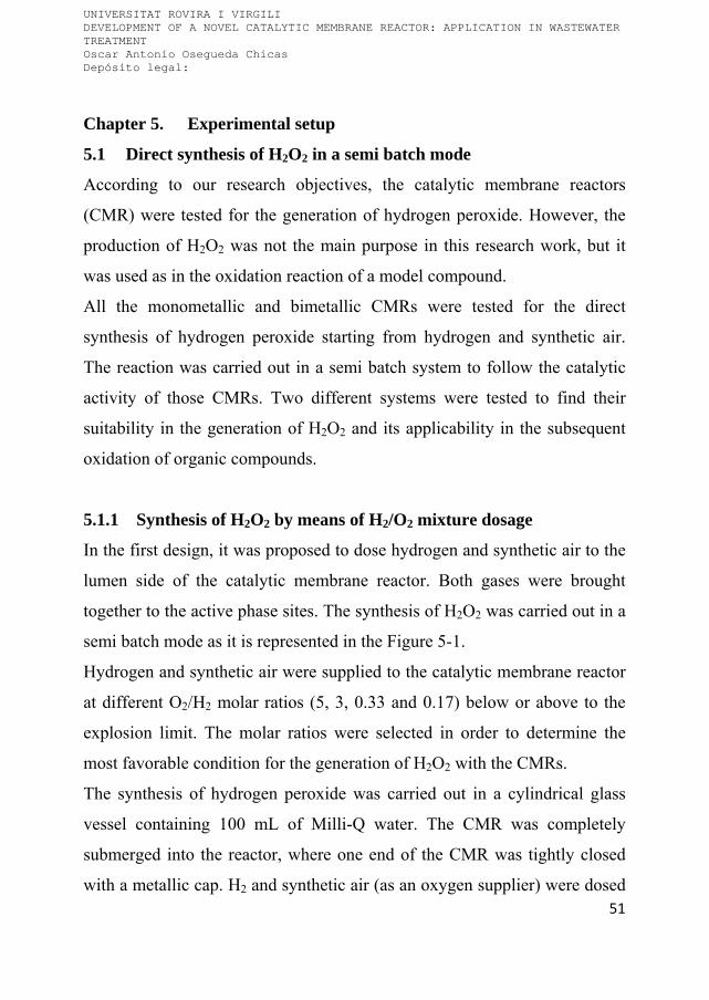
UNIVERSITAT ROVIRA I VIRGILI DEVELOPMENT OF A NOVEL CATALYTIC MEMBRANE REACTOR: APPLICATION IN WASTEWATER TREATMENT Oscar Antonio Osegueda Chicas Depósito legal:
51
Chapter 5. Experimental setup
5.1 Direct synthesis of H2O2 in a semi batch mode
According to our research objectives, the catalytic membrane reactors
(CMR) were tested for the generation of hydrogen peroxide. However, the
production of H2O2 was not the main purpose in this research work, but it
was used as in the oxidation reaction of a model compound.
All the monometallic and bimetallic CMRs were tested for the direct
synthesis of hydrogen peroxide starting from hydrogen and synthetic air.
The reaction was carried out in a semi batch system to follow the catalytic
activity of those CMRs. Two different systems were tested to find their
suitability in the generation of H2O2 and its applicability in the subsequent
oxidation of organic compounds.
5.1.1 Synthesis of H2O2 by means of H2/O2 mixture dosage
In the first design, it was proposed to dose hydrogen and synthetic air to the
lumen side of the catalytic membrane reactor. Both gases were brought
together to the active phase sites. The synthesis of H2O2 was carried out in a
semi batch mode as it is represented in the Figure 5-1.
Hydrogen and synthetic air were supplied to the catalytic membrane reactor
at different O2/H2 molar ratios (5, 3, 0.33 and 0.17) below or above to the
explosion limit. The molar ratios were selected in order to determine the
most favorable condition for the generation of H2O2 with the CMRs.
The synthesis of hydrogen peroxide was carried out in a cylindrical glass
vessel containing 100 mL of Milli-Q water. The CMR was completely
submerged into the reactor, where one end of the CMR was tightly closed
with a metallic cap. H2 and synthetic air (as an oxygen supplier) were dosed
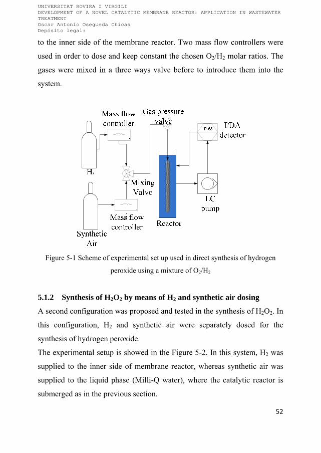
UNIVERSITAT ROVIRA I VIRGILI DEVELOPMENT OF A NOVEL CATALYTIC MEMBRANE REACTOR: APPLICATION IN WASTEWATER TREATMENT Oscar Antonio Osegueda Chicas Depósito legal:
52
to the inner side of the membrane reactor. Two mass flow controllers were
used in order to dose and keep constant the chosen O2/H2 molar ratios. The
gases were mixed in a three ways valve before to introduce them into the
system.
Figure 5-1 Scheme of experimental set up used in direct synthesis of hydrogen
peroxide using a mixture of O2/H2
5.1.2 Synthesis of H2O2 by means of H2 and synthetic air dosing
A second configuration was proposed and tested in the synthesis of H2O2. In
this configuration, H2 and synthetic air were separately dosed for the
synthesis of hydrogen peroxide.
The experimental setup is showed in the Figure 5-2. In this system, H2 was
supplied to the inner side of membrane reactor, whereas synthetic air was
supplied to the liquid phase (Milli-Q water), where the catalytic reactor is
submerged as in the previous section.

UNIVERSITAT ROVIRA I VIRGILI DEVELOPMENT OF A NOVEL CATALYTIC MEMBRANE REACTOR: APPLICATION IN WASTEWATER TREATMENT Oscar Antonio Osegueda Chicas Depósito legal:
53
The hydrogen flows through the membrane wall, and it is activated onto the
palladium surface. The synthetic air was dosed to the Milli-Q water
controlled by means of needle valve. The synthetic air flow was kept high in
order to dissolve the maximum amount of oxygen in the Milli-Q water. The
activated H2 reacts with the dissolved O2 into the aqueous phase.
Figure 5-2 Experimental set up used in direct synthesis of hydrogen peroxide
The H2 flow was controlled with a flow mass controller, and it was supplied
at 6 NmL min-1. The transmembrane gas pressures were recorded.
5.1.3 Reaction conditions, sampling and measurement of H2O2
In both configurations, the reactions were carried out at room temperature
(25 °C), and the glass vessel was kept at atmospheric pressure. The reaction
was monitored using a liquid chromatographic pump (Shimadzu, LC-20A)
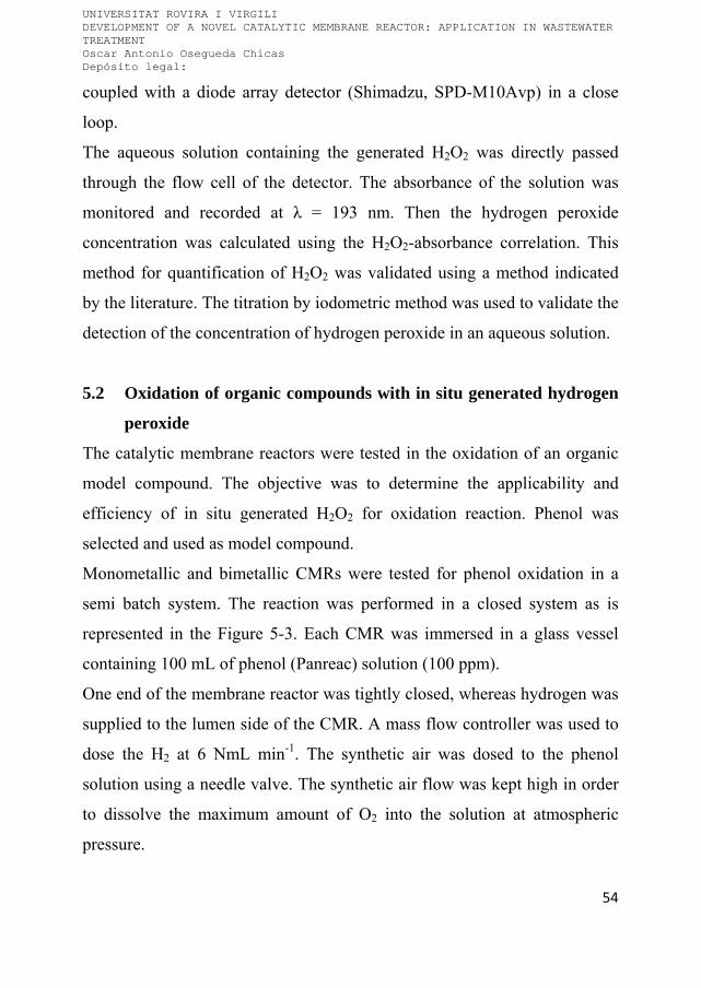
UNIVERSITAT ROVIRA I VIRGILI DEVELOPMENT OF A NOVEL CATALYTIC MEMBRANE REACTOR: APPLICATION IN WASTEWATER TREATMENT Oscar Antonio Osegueda Chicas Depósito legal:
54
coupled with a diode array detector (Shimadzu, SPD-M10Avp) in a close
loop.
The aqueous solution containing the generated H2O2 was directly passed
through the flow cell of the detector. The absorbance of the solution was
monitored and recorded at λ = 193 nm. Then the hydrogen peroxide
concentration was calculated using the H2O2-absorbance correlation. This
method for quantification of H2O2 was validated using a method indicated
by the literature. The titration by iodometric method was used to validate the
detection of the concentration of hydrogen peroxide in an aqueous solution.
5.2 Oxidation of organic compounds with in situ generated hydrogen
peroxide
The catalytic membrane reactors were tested in the oxidation of an organic
model compound. The objective was to determine the applicability and
efficiency of in situ generated H2O2 for oxidation reaction. Phenol was
selected and used as model compound.
Monometallic and bimetallic CMRs were tested for phenol oxidation in a
semi batch system. The reaction was performed in a closed system as is
represented in the Figure 5-3. Each CMR was immersed in a glass vessel
containing 100 mL of phenol (Panreac) solution (100 ppm).
One end of the membrane reactor was tightly closed, whereas hydrogen was
supplied to the lumen side of the CMR. A mass flow controller was used to
dose the H2 at 6 NmL min-1. The synthetic air was dosed to the phenol
solution using a needle valve. The synthetic air flow was kept high in order
to dissolve the maximum amount of O2 into the solution at atmospheric
pressure.

UNIVERSITAT ROVIRA I VIRGILI DEVELOPMENT OF A NOVEL CATALYTIC MEMBRANE REACTOR: APPLICATION IN WASTEWATER TREATMENT Oscar Antonio Osegueda Chicas Depósito legal:
55
The glass vessel with the CMR was introduced into a temperature
programmable bath system to work at different temperatures.
Figure 5-3 Experimental setup for phenol degradation by in situ generated
hydrogen peroxide
5.2.1 Sampling and measurement of phenol
The phenol degradation was monitored by sampling at regular time intervals
and analyzing by high performance liquid chromatography (HPLC,
Shimadzu LC-2010). The HPLC system is equipped with a diode array
detector (Shimadzu SPD-M10Avp).
A C-18 separation column (Omnisphere, Varian) was used to separate,
identify and quantify the compounds coming from the reaction. Calibration
curves for phenol (Panreac), hydroquinone (Sigma-Aldrich), cathecol
(Aldrich), and some carboxylic acids such as acrylic (Fluka), oxalic (Sigma-
Aldrich) and maleic acid (Panreac) were prepared from standard solutions.
UNIVERSITAT ROVIRA I VIRGILI DEVELOPMENT OF A NOVEL CATALYTIC MEMBRANE REACTOR: APPLICATION IN WASTEWATER TREATMENT Oscar Antonio Osegueda Chicas Depósito legal:
56
The solutions were prepared using the corresponding reagent. The mobile
phase was prepared with Milli-Q water and acetonitrile (Panreac) (60:40)
and adjusted at pH 3.8 with acetic acid (Fluka).
The mineralization degree was monitored with a TOC analyzer (TOC-
5000A, Shimadzu).
5.3 Design of metal housing (module reactor) for continuous
operation
Here, a metal housing design is proposed to be used as module reactor for
continuous operation of the catalytic membrane reactors. The housing was
built of stainless steel, and the Figure 5-4 shows an image of the housing.
The main body, where the membrane reactor is located, is 30 cm length with
0.9 cm of internal diameter. The metal housing is provided with two 3.175
mm axial feed connections, and two radial connections. One of the radial
connections is used as a gas feed connection (3.175 mm), and a pressure
gauge was connected to the second radial connection (6.5 mm) to monitor
the gas pressure in the system.
Figure 5-4 Image of the stainless steel reactor housing
Feed inlet Gas inlet
Feed outlet Connection to pressure gauge

UNIVERSITAT ROVIRA I VIRGILI DEVELOPMENT OF A NOVEL CATALYTIC MEMBRANE REACTOR: APPLICATION IN WASTEWATER TREATMENT Oscar Antonio Osegueda Chicas Depósito legal:
57
To operate this configuration, 30 cm length membrane reactors were
prepared by the impregnation method described in the section 4.1.4 above.
The loadings of active phases were kept constant to observe the catalytic
activity of the CMRs in this arrangement. In order to completely isolate the
permeate and the feed sides of the CMR, special tips have been fabricated at
each end of the membranes. Thereafter the both sides of the membrane are
isolated by using o-ring joints pressured between the nuts and the reactor
housing.
The ceramic seals were fabricated with commercial pottery (clay) material,
and a metal mold was used to give a desire form to the ceramic seals.
Firstly, each hollow fiber was centered and fixed in the middle of the mold,
and then the mold was full filled with the pottery material. Then, the hollow
fiber with the mold was introduced in an oven during night at 60 °C. After
one night, the mold was removed.
Afterward, the membrane with the clay seal was dried in an oven at 120 °C
during two hours, and then, the seals were cooked at 650 °C during 8 hours
to transform the clay into ceramic. Finally, the seals were covered with a
commercial inorganic glaze, followed by a calcinations step at 950 °C to
obtain an adequately vitrified ceramic seals. The deposition of the active
phase was carried out after the previous procedure, and the membrane
reactor was fixed in the steel house by means of Viton O-rings.
5.4 Catalytic reduction of water contaminants
The catalytic membrane reactors and the metal housing design were tested
in the catalytic reduction of water contaminants. The reactions were
operated under a continuous mode to observe the effectiveness of the
proposed system. Selective reduction of nitrates and hydrodechlorination of

UNIVERSITAT ROVIRA I VIRGILI DEVELOPMENT OF A NOVEL CATALYTIC MEMBRANE REACTOR: APPLICATION IN WASTEWATER TREATMENT Oscar Antonio Osegueda Chicas Depósito legal:
58
chlorinated aromatic compounds reactions were selected to observe the
catalytic activity under this operative mode.
5.4.1 Selective reduction of nitrates
The 30 cm length CMR6 (Pd-CeO2) and CMR12 (Pd-CeO2-Fe2O3/Al2O3)
were used in the selective reduction of nitrates. The Figure 5-5 shows the
experimental setup used to carry out the reaction in a continuous mode.
Each catalytic membrane reactor was placed into the metallic housing. The
feed solution was supplied by means a peristaltic pump at 15 mL min-1 to
the lumen side of the CMR.
Figure 5-5 Experimental setup for selective nitrate reduction
A nitrate solution (100 ppm) was prepared using NaNO3 (Sigma Aldrich)
and Milli-Q water. Whereas, H2 was dosed through the shell side by means
of a mass flow controller. Different H2 flows were used to perform this
reaction (6 and 10 NmL min-1). The reaction was carried out at 25 °C.

UNIVERSITAT ROVIRA I VIRGILI DEVELOPMENT OF A NOVEL CATALYTIC MEMBRANE REACTOR: APPLICATION IN WASTEWATER TREATMENT Oscar Antonio Osegueda Chicas Depósito legal:
59
The reaction was monitored with a colorimetric method using a color
photometer (Lovibond photometer). The nitrate concentration was measured
using standard Vario Nitrax reagent (detection range: 0.50 – 133 mg L-1),
the nitrite concentration was measured with Vario Nitrite reagent (detection
range: 0.03 – 1.6 mg L-1) and ammonia concentration was analyzed with
Vario AM tube test reagent (detection range: 0.03 – 3.25 mg L-1).
5.4.2 Hydrodechlorination of chlorinated aromatic compounds
The hydrodechlorination of chlorinated aromatic compounds was carried out
in a closed system as is represented in the Figure 5-6. The reaction was
performed with the 30 cm length CMR12 (Pd-CeO2-Fe2O3/Al2O3) in a
continuous operation mode. 4-Cl-Phenol (Sigma Aldrich) was used as
model compound, and formic acid (Panreac) was used as hydrogen donor.
Figure 5-6 Experimental setup for hydrodechlorination of 4-Cl-Phenol
Each membrane reactor was placed in a glass housing. The feed solution
was dosed at 10 mL min-1 to the lumen side of the CMR with a peristaltic

UNIVERSITAT ROVIRA I VIRGILI DEVELOPMENT OF A NOVEL CATALYTIC MEMBRANE REACTOR: APPLICATION IN WASTEWATER TREATMENT Oscar Antonio Osegueda Chicas Depósito legal:
60
pump (Masterflex L/S). The feed solution was a mixture of 4-Cl-phenol
(100 ppm) and formic acid (2000 ppm).
The progress of the reaction was monitored by sampling at regular intervals
and analyzing with a HPLC (HPLC, Shimadzu LC-2010) equipped with a
diode array detector (Shimadzu SPD-M10Avp). Then, the samples were
analyzed with the same protocol used in the phenol oxidation reaction.

UNIVERSITAT ROVIRA I VIRGILI DEVELOPMENT OF A NOVEL CATALYTIC MEMBRANE REACTOR: APPLICATION IN WASTEWATER TREATMENT Oscar Antonio Osegueda Chicas Depósito legal:
61
Chapter 6. Results and discussion
This chapter summarized the characterization and experimental results
obtained from the use of the catalytic membrane reactors.
6.1 Ceramic hollow fibers
The main objective of this work is the preparation of catalytic membrane
reactors. The starting materials were commercial ceramic hollow fibers as
catalyst support. The performance of the CMRs is intrinsically related with
the structural and morphological characteristic of the membrane support,
thus the hollow fibers were firstly studied by different techniques. The
found characteristics are used for better understanding of the catalytic
activities of the CMRs.
The Figure 6-1 shows an ESEM image of the cross section of the 4 nm
filtration pore size ceramic membrane.

UNIVERSITAT ROVIRA I VIRGILI DEVELOPMENT OF A NOVEL CATALYTIC MEMBRANE REACTOR: APPLICATION IN WASTEWATER TREATMENT Oscar Antonio Osegueda Chicas Depósito legal:
62
Figure 6-1 ESEM image obtained from the cross section of the 4 nm filtration pore
size hollow fiber
The cross section reveals a symmetric structure as well as the absence of
skin layer. The thickness is mainly formed by a dense sponge like structure,
also finger like structures (small black dots) are observed. During the
membrane fabrication process, the fingers like structures are formed at the
sintering step, and offer an optimal place where the active phases can be
deposited [158]. The sponge like structure provides mechanical resistance to
the ceramic membranes.
Figure 6-2 shows an ESEM image obtained from the cross section of the
1400 nm hollow fiber. As in the 4 nm ceramic fiber, it was also observed a
symmetric cross section with a sponge like structure. As it was previously
observed, small finger like structures are present in the fiber. Whereas
Figure 6-3 shows a magnified image from the bulk of the 1400 nm, and

UNIVERSITAT ROVIRA I VIRGILI DEVELOPMENT OF A NOVEL CATALYTIC MEMBRANE REACTOR: APPLICATION IN WASTEWATER TREATMENT Oscar Antonio Osegueda Chicas Depósito legal:
63
offers a closed image of a high dense packing of particles, which form the
core of the membrane.
Figure 6-2 Image of the cross section of 1400 nm hollow fiber
The rest of the hollow fibers were observed by means ESEM microscopy
technique, and as it was observed in the previous membranes, symmetric
cross section with sponge like structure were detected in all cases.

UNIVERSITAT ROVIRA I VIRGILI DEVELOPMENT OF A NOVEL CATALYTIC MEMBRANE REACTOR: APPLICATION IN WASTEWATER TREATMENT Oscar Antonio Osegueda Chicas Depósito legal:
64
Figure 6-3 ESEM image of bulk of 1400 nm hollow fiber
The sponge like structure identified in the commercial hollow fibers
represented an important feature for gas-liquid applications. Hollow fibers
with uniform structure provide flow resistance through the entire thickness
of the ceramic membrane [159-160].
The μ-XRD analysis was conducted over the hollow fibers. The Figure 6-4
and Figure 6-5 show the XRD diffractograms from the 4 and 20 nm ceramic
membranes, respectively. The analysis was carried out over the internal and
external surfaces. The identification of the crystal structures were achieved
by comparison of the XRD diffractogram with the ICDD data base (release
2007) using Diffracplus Evaluation software (Brucker 2007). An unique
crystal phase was detected corresponding to α-Al2O3. The XRD results
demonstrate that the used ceramic fibers have a homogeneous corundum
composition along the inner and outer surface.

UNIVERSITAT ROVIRA I VIRGILI DEVELOPMENT OF A NOVEL CATALYTIC MEMBRANE REACTOR: APPLICATION IN WASTEWATER TREATMENT Oscar Antonio Osegueda Chicas Depósito legal:
65
Figure 6-4 μ-XRD analysis carried out over the 4 nm hollow fiber
N2 adsorption at -196 °C analysis was carried out over the parent fibers used
in the preparation of the CRMs. The apparent specific surface area (aSSA)
was calculated by application of the BET model to the N2 adsorption –
desorption isotherms, and it was 3 m2 g-1 for all the hollow fibers. This aSSA
is typical for the corundum that is the fabrication material of the used
membranes. It is nonporous, and the main pore network is generated by the
interparticles voids.
00-046-1212 (*) - Corundum, syn - Al2O34nm-Al2O3 (1)), 500um, 15cm, 300s [007] - File: d8_arj49013_01 [007].raw - X: -0.707 mm - Y: -8.230
4nm-Al2O3 (1)), 500um, 15cm, 300s [006] - File: d8_arj49013_01 [006].raw - X: -1.207 mm - Y: -8.230 4nm-Al2O3 (1)), 500um, 15cm, 300s [005] - File: d8_arj49013_01 [005].raw - X: -1.707 mm - Y: -8.230 4nm-Al2O3 (1)), 500um, 15cm, 300s [004] - File: d8_arj49013_01 [004].raw - X: -2.207 mm - Y: -8.230
4nm-Al2O3 (1)), 500um, 15cm, 300s [003] - File: d8_arj49013_01 [003].raw - X: -2.707 mm - Y: -8.230 4nm-Al2O3 (1)), 500um, 15cm, 300s [002] - File: d8_arj49013_01 [002].raw - X: -3.207 mm - Y: -8.230
Lin
(C
oun
ts)
0
100
200
300
400
Phi scale
25 30 40 50
2-Theta - Scale

UNIVERSITAT ROVIRA I VIRGILI DEVELOPMENT OF A NOVEL CATALYTIC MEMBRANE REACTOR: APPLICATION IN WASTEWATER TREATMENT Oscar Antonio Osegueda Chicas Depósito legal:
66
Figure 6-5 μ-XRD analysis performed over the 20 nm hollow fiber
6.2 Monometallic Pd membrane reactors
Monometallic Pd membrane reactors were prepared by two different
protocols: i) impregnation and ii) developed novel sputtering protocol. By
the sputtering method the amount of Pd is highly reduced, e.g. in the case of
the sCMR13 the amount of Pd loaded onto the membrane reactor was
reduced up to 260 times compared with the CMR prepared by impregnation.
Moreover, the sputtering protocol allowed the selective deposition of the
noble metal over the external surface of the ceramic fiber, where the
reaction takes place.
The monometallic Pd membrane reactors were analyzed by ESEM, and the
analysis has shown that the morphology of the ceramic membranes do not
seem to be modified after palladium deposition.
00-046-1212 (*) - Corundum, syn - Al2O3
20nm-Al2O3 (1), 500um, 15cm, 300s [007] - File: d8_arj49015_01 [007].raw - X: -1.608 mm - Y: 3.336
20nm-Al2O3 (1), 500um, 15cm, 300s [006] - File: d8_arj49015_01 [006].raw - X: -2.108 mm - Y: 3.336 20nm-Al2O3 (1), 500um, 15cm, 300s [005] - File: d8_arj49015_01 [005].raw - X: -2.608 mm - Y: 3.336
20nm-Al2O3 (1), 500um, 15cm, 300s [004] - File: d8_arj49015_01 [004].raw - X: -3.108 mm - Y: 3.336 20nm-Al2O3 (1), 500um, 15cm, 300s [003] - File: d8_arj49015_01 [003].raw - X: -3.608 mm - Y: 3.336
20nm-Al2O3 (1), 500um, 15cm, 300s [002] - File: d8_arj49015_01 [002].raw - X: -4.108 mm - Y: 3.336
Lin
(C
ount
s)
0
100
200
300
Phi scale
25 30 40 50
2-Theta - Scale

UNIVERSITAT ROVIRA I VIRGILI DEVELOPMENT OF A NOVEL CATALYTIC MEMBRANE REACTOR: APPLICATION IN WASTEWATER TREATMENT Oscar Antonio Osegueda Chicas Depósito legal:
67
Figure 6-6 shows a close image from the outer surface of the CMR1. There
is no evidence of morphological changes in the α-Al2O3 particles in the
surface, and the filtration pore were not closed by the incorporation of the
noble metal.
The internal surface of the CMR3 is shown in the Figure 6-7, and as well
the CMR1, there are not proofs of alteration of the corundum particles of the
hollow fiber. Also, the rest of CMRs prepared by impregnation do not
reflect appreciable changes in the morphological structure, which is
important to keep the integrity of the membrane.
Figure 6-6 ESEM image of the external surface of the monometallic palladium
membrane reactor (CMR1)

UNIVERSITAT ROVIRA I VIRGILI DEVELOPMENT OF A NOVEL CATALYTIC MEMBRANE REACTOR: APPLICATION IN WASTEWATER TREATMENT Oscar Antonio Osegueda Chicas Depósito legal:
68
Figure 6-7 Close ESEM image of the internal surface of the CMR3
The membrane reactor prepared by sputtering procedure is shown in the
Figure 6-8. The morphology of the external surface is the same as for the
starting membrane. In fact, the filtration pores are present and there is no
evidence of Pd clusters growing over the ceramic membrane surface.
Also, the CMRs were examined by ESEM in backscattering mode (ESEM-
BSE). The Figure 6-9 shows the external surface of the CMR5. The
impregnation method leads to the formation of Pd cluster over the alumina
particles. The noble metal is found to be homogeneously distributed over
the entire surface. The rest of monometallic Pd membrane reactors, prepared
by the same method, have presented similar distribution of Pd over the
external and internal surfaces. Therefore, the porosity of the membrane does
not present steric limitations to the ions from the precursor solution.
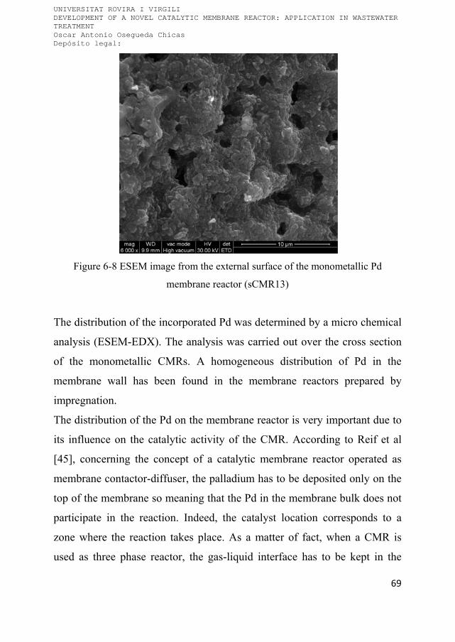
UNIVERSITAT ROVIRA I VIRGILI DEVELOPMENT OF A NOVEL CATALYTIC MEMBRANE REACTOR: APPLICATION IN WASTEWATER TREATMENT Oscar Antonio Osegueda Chicas Depósito legal:
69
Figure 6-8 ESEM image from the external surface of the monometallic Pd
membrane reactor (sCMR13)
The distribution of the incorporated Pd was determined by a micro chemical
analysis (ESEM-EDX). The analysis was carried out over the cross section
of the monometallic CMRs. A homogeneous distribution of Pd in the
membrane wall has been found in the membrane reactors prepared by
impregnation.
The distribution of the Pd on the membrane reactor is very important due to
its influence on the catalytic activity of the CMR. According to Reif et al
[45], concerning the concept of a catalytic membrane reactor operated as
membrane contactor-diffuser, the palladium has to be deposited only on the
top of the membrane so meaning that the Pd in the membrane bulk does not
participate in the reaction. Indeed, the catalyst location corresponds to a
zone where the reaction takes place. As a matter of fact, when a CMR is
used as three phase reactor, the gas-liquid interface has to be kept in the

UNIVERSITAT ROVIRA I VIRGILI DEVELOPMENT OF A NOVEL CATALYTIC MEMBRANE REACTOR: APPLICATION IN WASTEWATER TREATMENT Oscar Antonio Osegueda Chicas Depósito legal:
70
zone where the active phase is located. The amount of noble metal dispersed
out of the catalytic zone will not participate in the reaction [161].
In our case, the impregnation method allowed us to incorporate the active
phases to the membrane. However, the selective deposition of the Pd is
limited and no special efforts in this direction have been done using this
method. Thus, the wetness impregnation method is very easily applicable
but increases the amount of Pd used in the preparation of the CMRs, and
consequently increases the cost of the membrane reactors.
Figure 6-9 BSE image of the external surface of the CMR5
The main goal of the developed method for CMR preparation by sputtering
is to avoid the over dosage of Pd.
A representative example of the CMRs prepared by sputtering is the
sCMR13. The sputtered Pd monometallic membrane reactor presents a
different distribution of the noble metal on the ceramic membrane. As it is

UNIVERSITAT ROVIRA I VIRGILI DEVELOPMENT OF A NOVEL CATALYTIC MEMBRANE REACTOR: APPLICATION IN WASTEWATER TREATMENT Oscar Antonio Osegueda Chicas Depósito legal:
71
shown in the Figure 6-10, the Pd is selectively located over the top layer of
the outer surface. The EDX analysis shows that Pd was selectively
deposited over the external surface. The distances shown in the figure have
been measured starting from the external surface to the bulk of the ceramic
membrane. The Pd is located in the upper layer, 10 μm from the top of the
external surface, and afterward it was not detected any signal of the noble
metal in the bulk of the fiber. The exposure time in the sputtering chamber
as well as the roughness of the membrane surface are factors that prevent
the formation of continuous Pd layer over the hollow fiber.
0 5 10 15 20 25
0.0
0.5
1.0
1.5
2.0
2.5
3.0
3.5
4.0
Pd Al O
Distance (m)
Pd
Dis
trib
utio
n (w
t %)
45.0
46.5
48.0
49.5
51.0
52.5
Ceram
ic support (wt %
)
Figure 6-10 Pd distribution on the monometallic Pd membrane reactor (sCMR13)
Also, an element mapping of the external surface of the sCMR13 using the
backscatter detector was performed. The Pd dispersion over a selected area
is shown in the Figure 6-11. From the image we can conclude that the noble
metal is homogeneous and finely dispersed over the entire surface of the

UNIVERSITAT ROVIRA I VIRGILI DEVELOPMENT OF A NOVEL CATALYTIC MEMBRANE REACTOR: APPLICATION IN WASTEWATER TREATMENT Oscar Antonio Osegueda Chicas Depósito legal:
72
membrane reactor. The high dispersion of Pd over the membrane surface
can improve the catalytic activity of the CMR. This feature is an important
step to increase the efficiency of the noble metal.
As it was expected, the novel procedure to incorporate Pd by means
sputtering protocol presents a high efficiency for the selective deposition of
the active metal on the external surface of the hollow fiber. Likewise, this
method reduces the amount of Pd used in the preparation of the catalytic
membrane reactor.
Figure 6-11 Electron mapping of different elements from the external surface of the
sCMR13
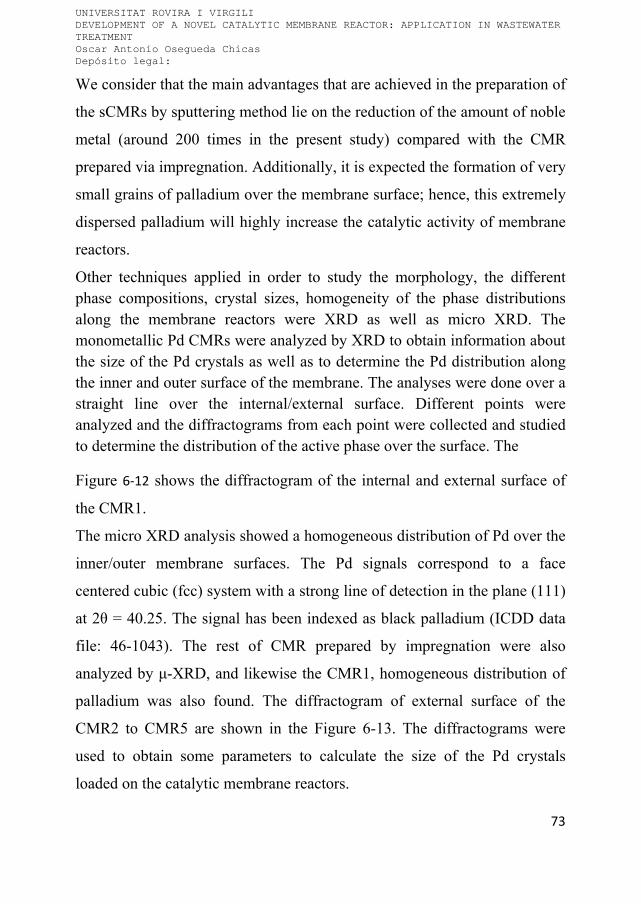
UNIVERSITAT ROVIRA I VIRGILI DEVELOPMENT OF A NOVEL CATALYTIC MEMBRANE REACTOR: APPLICATION IN WASTEWATER TREATMENT Oscar Antonio Osegueda Chicas Depósito legal:
73
We consider that the main advantages that are achieved in the preparation of
the sCMRs by sputtering method lie on the reduction of the amount of noble
metal (around 200 times in the present study) compared with the CMR
prepared via impregnation. Additionally, it is expected the formation of very
small grains of palladium over the membrane surface; hence, this extremely
dispersed palladium will highly increase the catalytic activity of membrane
reactors.
Other techniques applied in order to study the morphology, the different phase compositions, crystal sizes, homogeneity of the phase distributions along the membrane reactors were XRD as well as micro XRD. The monometallic Pd CMRs were analyzed by XRD to obtain information about the size of the Pd crystals as well as to determine the Pd distribution along the inner and outer surface of the membrane. The analyses were done over a straight line over the internal/external surface. Different points were analyzed and the diffractograms from each point were collected and studied to determine the distribution of the active phase over the surface. The
Figure 6‐12 shows the diffractogram of the internal and external surface of
the CMR1.
The micro XRD analysis showed a homogeneous distribution of Pd over the
inner/outer membrane surfaces. The Pd signals correspond to a face
centered cubic (fcc) system with a strong line of detection in the plane (111)
at 2θ = 40.25. The signal has been indexed as black palladium (ICDD data
file: 46-1043). The rest of CMR prepared by impregnation were also
analyzed by μ-XRD, and likewise the CMR1, homogeneous distribution of
palladium was also found. The diffractogram of external surface of the
CMR2 to CMR5 are shown in the Figure 6-13. The diffractograms were
used to obtain some parameters to calculate the size of the Pd crystals
loaded on the catalytic membrane reactors.

UNIVERSITAT ROVIRA I VIRGILI DEVELOPMENT OF A NOVEL CATALYTIC MEMBRANE REACTOR: APPLICATION IN WASTEWATER TREATMENT Oscar Antonio Osegueda Chicas Depósito legal:
74
The palladium crystal size was calculated using the Scherrer equation:
cos
180
Where τ is the size of the crystal in nm, λ is the X-ray wavelength, k is a
dimensionless shape factor, ß is the net broadening of the peak calculated as
ß2 = ß2obs – ß2
ins, and θ is the Bragg angle.
a)
00-046-1043 (*) - Palladium, syn - Pd - Y: 14.22 % - d x by: 1. - WL: 1.54056 - Cubic - a 3.89019 - b 3.89Operations: Import [008]4nm-Pd-Al2O3 (1) [008] - File: d8_arj49002 [008].raw - Type: 2Th alone - Start: 24.900 ° - End: 58.900 ° Operations: Import [007]
4nm-Pd-Al2O3 (1) [007] - File: d8_arj49002 [007].raw - Type: 2Th alone - Start: 24.900 ° - End: 58.900 °
Operations: Import [006]4nm-Pd-Al2O3 (1) [006] - File: d8_arj49002 [006].raw - Type: 2Th alone - Start: 24.900 ° - End: 58.900 ° Operations: Import [005]4nm-Pd-Al2O3 (1) [005] - File: d8_arj49002 [005].raw - Type: 2Th alone - Start: 24.900 ° - End: 58.900 ° Operations: Import [004]4nm-Pd-Al2O3 (1) [004] - File: d8_arj49002 [004].raw - Type: 2Th alone - Start: 24.900 ° - End: 58.900 ° Operations: Import [003]
4nm-Pd-Al2O3 (1) [003] - File: d8_arj49002 [003].raw - Type: 2Th alone - Start: 24.900 ° - End: 58.900 °
Lin
(Cou
nts)
0
100
200
300
2-Theta - Scale
25 30 40 50

UNIVERSITAT ROVIRA I VIRGILI DEVELOPMENT OF A NOVEL CATALYTIC MEMBRANE REACTOR: APPLICATION IN WASTEWATER TREATMENT Oscar Antonio Osegueda Chicas Depósito legal:
75
b)
Figure 6-12 μ-XRD analysis performed over the a) internal and b) external surface
of the CMR1
In the Table 6-1 summarized the sizes of Pd crystals calculated by Scherrer
equation. And as it was expected, the sizes of the Pd crystal vary depending
of the starting filtration pore size of the hollow fiber. The lower value of Pd
crystal was found in the CMR1.
00-046-1043 (*) - Palladium, syn - Pd - Y: 13.05 % - d x by: 1. - WL: 1.54056 - Cubic - a 3.89019 Operations: Import [008]4nm-Pd-Al2O3 (2) [008] - File: d8_arj49003 [008] .raw - Type: 2Th alone - Start: 24.900 ° - End: 5Operations: Import [007]4nm-Pd-Al2O3 (2) [007] - File: d8_arj49003 [007] .raw - Type: 2Th alone - Start: 24.900 ° - End: 5Operations: Import [006]
4nm-Pd-Al2O3 (2) [006] - File: d8_arj49003 [006] .raw - Type: 2Th alone - Start: 24.900 ° - End: 5
Operat ions: Import [005]4nm-Pd-Al2O3 (2) [005] - File: d8_arj49003 [005].raw - Type: 2Th alone - Start: 24.900 ° - End: 58.900 ° Operat ions: Import [004]4nm-Pd-Al2O3 (2) [004] - File: d8_arj49003 [004].raw - Type: 2Th alone - Start: 24.900 ° - End: 58.900 ° Operat ions: Import [003]4nm-Pd-Al2O3 (2) [003] - File: d8_arj49003 [003].raw - Type: 2Th alone - Start: 24.900 ° - End: 58.900 ° Operat ions: Import [002]
4nm-Pd-Al2O3 (2) [002] - File: d8_arj49003 [002].raw - Type: 2Th alone - Start: 24.900 ° - End: 58.900 °
Lin
(Cou
nts)
0
10
20
30
40
50
60
70
80
90
100
110
120
130
140
150
160
170
180
190
200
210
220
230
240
250
260
270
280
290
300
310
2-Theta - Scale
25 30 40 50
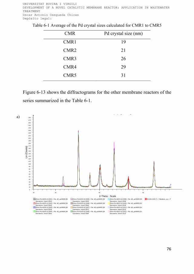
UNIVERSITAT ROVIRA I VIRGILI DEVELOPMENT OF A NOVEL CATALYTIC MEMBRANE REACTOR: APPLICATION IN WASTEWATER TREATMENT Oscar Antonio Osegueda Chicas Depósito legal:
76
Table 6-1 Average of the Pd crystal sizes calculated for CMR1 to CMR5
CMR Pd crystal size (nm)
CMR1 19
CMR2 21
CMR3 26
CMR4 29
CMR5 31
Figure 6-13 shows the diffractograms for the other membrane reactors of the
series summarized in the Table 6-1.
a)
( ) [ ]
00-046-1043 (*) - Palladium, syn - Pd
Operations: Import [012]20nm-Pd-Al2O3 (2) [012] - File: d8_arj49005 [01Operations: Import [011]20nm-Pd-Al2O3 (2) [011] - File: d8_arj49005 [01Operations: Import [010]20nm-Pd-Al2O3 (2) [010] - File: d8_arj49005 [01Operations: Import [009]
20nm-Pd-Al2O3 (2) [009] - File: d8_arj49005 [00
Operations: Import [008]20nm-Pd-Al2O3 (2) [008] - File: d8_arj49005 [00Operations: Import [007]20nm-Pd-Al2O3 (2) [007] - File: d8_arj49005 [00Operations: Import [006]20nm-Pd-Al2O3 (2) [006] - File: d8_arj49005 [00Operations: Import [005]
20nm-Pd-Al2O3 (2) [005] - File: d8_arj49005 [00
Operat ions: Import [004]20nm-Pd-Al2O3 (2) [004] - File: d8_arj49005 [00Operat ions: Import [003]20nm-Pd-Al2O3 (2) [003] - File: d8_arj49005 [00Operat ions: Import [002]20nm-Pd-Al2O3 (2) [002] - File: d8_arj49005 [00Operat ions: Import [001]
20nm-Pd-Al2O3 (2) [001] - File: d8_arj49005 [00
Lin
(Cou
nts)
0
10
20
30
40
50
60
70
80
90
100
110
120
130
140
150
160
170
180
190
200
210
220
230
240
250
260
270
280
2-Theta - Scale
25 30 40 50

UNIVERSITAT ROVIRA I VIRGILI DEVELOPMENT OF A NOVEL CATALYTIC MEMBRANE REACTOR: APPLICATION IN WASTEWATER TREATMENT Oscar Antonio Osegueda Chicas Depósito legal:
77
b)
c)
00-046-1043 (*) - Palladium, syn - Pd - Y: 3.14 % - d x by: 1. - WL: 1.54056 - Cubic - a 3.8901Operations: Import [006]
100nm-Pd-Al2O3 (2) [006] - File: d8_arj49007 [006].raw - Type: 2Th alone - Start: 24.900 ° - E
Operat ions: Import [005]100nm-Pd-Al2O3 (2) [005] - File: d8_arj49007 [005].raw - Type: 2Th alone - Start: 24.900 ° - End: 58.900Operat ions: Import [004]100nm-Pd-Al2O3 (2) [004] - File: d8_arj49007 [004].raw - Type: 2Th alone - Start: 24.900 ° - End: 58.900Operat ions: Import [003]100nm-Pd-Al2O3 (2) [003] - File: d8_arj49007 [003].raw - Type: 2Th alone - Start: 24.900 ° - End: 58.900Operat ions: Import [002]
100nm-Pd-Al2O3 (2) [002] - File: d8_arj49007 [002].raw - Type: 2Th alone - Start: 24.900 ° - End: 58.900
Lin
(Cou
nts)
0
100
200
300
400
2-Theta - Scale
25 30 40 50
00-046-1043 (*) - Palladium, syn - Pd - Y: 2.82 % - d x by: 1. - WL:
Operations: Import [008]500nm-Pd-A l2O3 (2) [008] - File: d8_arj49009 [008].raw - Type: 2ThOperations: Import [007]500nm-Pd-A l2O3 (2) [007] - File: d8_arj49009 [007].raw - Type: 2ThOperations: Import [006]500nm-Pd-A l2O3 (2) [006] - File: d8_arj49009 [006].raw - Type: 2ThOperations: Import [005]
500nm-Pd-A l2O3 (2) [005] - File: d8_arj49009 [005].raw - Type: 2Th
Operat ions: Import [004]500nm-Pd-Al2O3 (2) [004] - File: d8_arj49009 [004].raw - Type: 2ThOperat ions: Import [003]500nm-Pd-Al2O3 (2) [003] - File: d8_arj49009 [003].raw - Type: 2ThOperat ions: Import [002]500nm-Pd-Al2O3 (2) [002] - File: d8_arj49009 [002].raw - Type: 2ThOperat ions: Import [001]
500nm-Pd-Al2O3 (2) [001] - File: d8_arj49009 [001].raw - Type: 2Th
Lin
(Cou
nts)
0
100
200
300
400
500
2-Theta - Scale
25 30 40 50

UNIVERSITAT ROVIRA I VIRGILI DEVELOPMENT OF A NOVEL CATALYTIC MEMBRANE REACTOR: APPLICATION IN WASTEWATER TREATMENT Oscar Antonio Osegueda Chicas Depósito legal:
78
d)
Figure 6-13 μ-XRD analysis carried out over the external surface of the a) CMR2,
b) CMR3, c) CMR4 and d) CMR5
The membrane reactors obtained after Pd sputtering have also been studied
by micro XRD technique. The diffractogram of sCMR13 is presented in
Figure 6-14. The time of data collection at each step (0.004º) was
maintained for 300 seconds. The signal of palladium phase was not
detected. The analysis time was increased up to 900 second per frame
without any incidence of Pd signal. We consider that the main reason for the
absence of palladium signal is due to the extremely tiny Pd grain size.
Despite the high concentration of the Pd on the outer surface of the
00-046-1043 (*) - Palladium, syn - Pd - Y: 23.58 % - d x by: 1. - WL:
Operations: Import [010]1400nm-Pd-Al2O3 (2) [010] - File: d8_arj49011 [010].raw - Type: 2TOperations: Import [009]1400nm-Pd-Al2O3 (2) [009] - File: d8_arj49011 [009].raw - Type: 2TOperations: Import [008]1400nm-Pd-Al2O3 (2) [008] - File: d8_arj49011 [008].raw - Type: 2TOperations: Import [007]
1400nm-Pd-Al2O3 (2) [007] - File: d8_arj49011 [007].raw - Type: 2T
Operations: Import [005]1400nm-Pd-Al2O3 (2) [005] - File: d8_arj49011 [005].raw - Type: 2TOperations: Import [004]1400nm-Pd-Al2O3 (2) [004] - File: d8_arj49011 [004].raw - Type: 2TOperations: Import [003]1400nm-Pd-Al2O3 (2) [003] - File: d8_arj49011 [003].raw - Type: 2TOperations: Import [002]
1400nm-Pd-Al2O3 (2) [002] - File: d8_arj49011 [002].raw - Type: 2T
Lin
(Cou
nts)
0
10
20
30
40
50
60
70
80
90
100
110
120
130
140
150
160
170
180
190
200
210
220
230
240
250
260
270
280
290
300
310
2-Theta - Scale
25 30 40 50

UNIVERSITAT ROVIRA I VIRGILI DEVELOPMENT OF A NOVEL CATALYTIC MEMBRANE REACTOR: APPLICATION IN WASTEWATER TREATMENT Oscar Antonio Osegueda Chicas Depósito legal:
79
membrane reactor it is believed that the Pd particles are extremely small,
below 5 nm.
Figure 6-14 μ-XRD analysis carried out over the sCMR13
6.3 Palladium bimetallic membrane reactors
Palladium bimetallic membrane reactors were characterized with an ESEM microscope. As well as the monometallic CMRs, the ESEM images obtained from the bimetallic membrane reactors did not reveal any structural and morphological difference between the parent and the modified hollow fibers.
Figure 6‐15 shows ESEM images from the external surface of sCMR15, and
the surface seems as the original ceramic fiber.
Also, the Pd bimetallic membrane reactors were examined by μ-XRD
analysis to identify the different crystal phases loaded on the catalytic
00-046-1043 (*) - Palladium, syn - Pd
03-065-5923 (A) - Cerium Oxide - CeO2
00-046-1212 (*) - Corundum, syn - Al2O3File: d8_arj49023 [003].raw - Creation: 16/02/2012 17:35:36 - X: -9.000 mm - Y: -2.390 mm
File: d8_arj49023 [002].raw - Creation: 16/02/2012 17:35:36 - X: 0.000 mm - Y: -1.928 mmFile: d8_arj49023 [001].raw - Creation: 16/02/2012 17:35:36 - X: 9.000 mm - Y: -1.928 mm
Lin
(C
oun
ts)
0
100
200
300
400
500
600
700
2-Theta - Scale
25 30 40 50

UNIVERSITAT ROVIRA I VIRGILI DEVELOPMENT OF A NOVEL CATALYTIC MEMBRANE REACTOR: APPLICATION IN WASTEWATER TREATMENT Oscar Antonio Osegueda Chicas Depósito legal:
80
membrane reactor. The Figure 6-16 shows the diffractogram of the CMR7.
Two different phases were detected in the ceramic membrane. Black
palladium crystals were detected as in the monometallic Pd CMRs. Also,
cerium oxide was detected at 2θ angles of 28.62, 33.15, 47.58 and 56.45
with a correspondence to ICDD data file 03-065-5923. The diffractogram of
sCMR15 with the same crystal phases as the CMR7 is shown in the Figure
6-17.

UNIVERSITAT ROVIRA I VIRGILI DEVELOPMENT OF A NOVEL CATALYTIC MEMBRANE REACTOR: APPLICATION IN WASTEWATER TREATMENT Oscar Antonio Osegueda Chicas Depósito legal:
81
a)
b)
Figure 6-15 ESEM images of the sCMR15 a) electronic image and b)
Backscattering mode image
The analysis was carried out during 900 second to observe Pd signal in the
specific 2θ angles. Despite the large time of signal detection at specific 2θ

UNIVERSITAT ROVIRA I VIRGILI DEVELOPMENT OF A NOVEL CATALYTIC MEMBRANE REACTOR: APPLICATION IN WASTEWATER TREATMENT Oscar Antonio Osegueda Chicas Depósito legal:
82
angle the Pd phase is difficult to be confirmed which can be expected due to
the small amount of Pd as well as the very small crystal size.
Figure 6-16 μ-XRD analysis carried out over bimetallic catalytic membrane reactor
(CMR7)
The Figure 6-18 shows the micro XRD analysis carried out over the CMR9.
Black Pd and TiO2 crystals phases are present in the membrane reactor.
03-065-5923 (C) - Cerium Oxide - CeO2 - Y: 32.36 % - d x by: 1. - W L: 1.54056 - Cubic - a 5.40370 - b 5.
00-046-1212 (*) - Corundum, syn - Al2O3 - Y: 89.96 % - d x by: 1. - WL: 1.54056 - Rhombo.H.axes - a 4.
00-046-1043 (*) - Palladium, syn - Pd - Y: 62.57 % - d x by: 1. - W L: 1.54056 - Cubic - a 3.89019 - b 3.89
Operat ions: Import [003]
M3 Ce Oxide-Fe oxide P d/Al2O3, 15cm, 900s [003] - F ile: d8_arj49024 [003] .raw - Type: 2Th alone - StaOperat ions: Import [002]
M3 Ce Oxide-Fe oxide P d/Al2O3, 15cm, 900s [002] - F ile: d8_arj49024 [002] .raw - Type: 2Th alone - Sta
Operat ions: Import [001]
M3 Ce Oxide-Fe oxide P d/Al2O3, 15cm, 900s [001] - F ile: d8_arj49024 [001] .raw - Type: 2Th alone - Sta
Lin
(Co
unts
)
0
100
200
300
400
2-Theta - Scale
25 30 40 50

UNIVERSITAT ROVIRA I VIRGILI DEVELOPMENT OF A NOVEL CATALYTIC MEMBRANE REACTOR: APPLICATION IN WASTEWATER TREATMENT Oscar Antonio Osegueda Chicas Depósito legal:
83
Figure 6-17 Diffractogram obtained from the bimetallic CeO2 – sputtered Pd,
sCMR15
The rest of crystal phases loaded on the catalytic membrane reactor were
confirmed with the μ-XRD analysis.
( )
03-065-5923 (C) - Cerium Oxide - CeO2 - Y: 30.44 % - d x by: 1. -
00-046-1043 (*) - Palladium, syn - Pd - Y: 10.16 % - d x by: 1. - WL:
Operations: Import [011]
CePdS-M100-Oxi Red (2) [011] - File: d8_arj49018 [011].raw - Type
Operations: Import [010]
CePdS-M100-Oxi Red (2) [010] - File: d8_arj49018 [010].raw - Type
Operations: Import [009]
CePdS-M100-Oxi Red (2) [009] - File: d8_arj49018 [009].raw - Type
Operations: Import [008]
CePdS-M100-Oxi Red (2) [008] - File: d8_arj49018 [008].raw - Type
Operations: Import [007]
CePdS-M100-Oxi Red (2) [007] - File: d8_arj49018 [007].raw - Type
Operations: Import [006]
CePdS-M100-Oxi Red (2) [006] - File: d8_arj49018 [006].raw - Type
Operations: Import [005]
CePdS-M100-Oxi Red (2) [005] - File: d8_arj49018 [005].raw - Type
Operations: Import [004]
CePdS-M100-Oxi Red (2) [004] - File: d8_arj49018 [004].raw - Type
Operations: Import [003]
CePdS-M100-Oxi Red (2) [003] - File: d8_arj49018 [003].raw - Type
Operations: Import [002]
CePdS-M100-Oxi Red (2) [002] - File: d8_arj49018 [002].raw - Type
Operations: Import [001]
CePdS-M100-Oxi Red (2) [001] - File: d8_arj49018 [001].raw - Type
Lin
(Co
unts
)
0
10
20
30
40
50
60
70
80
90
100
110
120
130
140
150
160
170
180
2-Theta - Scale
25 30 40 50
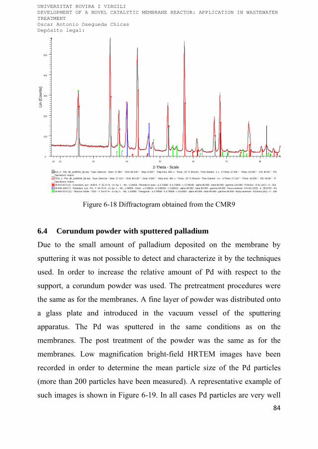
UNIVERSITAT ROVIRA I VIRGILI DEVELOPMENT OF A NOVEL CATALYTIC MEMBRANE REACTOR: APPLICATION IN WASTEWATER TREATMENT Oscar Antonio Osegueda Chicas Depósito legal:
84
Figure 6-18 Diffractogram obtained from the CMR9
6.4 Corundum powder with sputtered palladium
Due to the small amount of palladium deposited on the membrane by
sputtering it was not possible to detect and characterize it by the techniques
used. In order to increase the relative amount of Pd with respect to the
support, a corundum powder was used. The pretreatment procedures were
the same as for the membranes. A fine layer of powder was distributed onto
a glass plate and introduced in the vacuum vessel of the sputtering
apparatus. The Pd was sputtered in the same conditions as on the
membranes. The post treatment of the powder was the same as for the
membranes. Low magnification bright-field HRTEM images have been
recorded in order to determine the mean particle size of the Pd particles
(more than 200 particles have been measured). A representative example of
such images is shown in Figure 6-19. In all cases Pd particles are very well
03-065-5714 (C) - Titanium Oxide - TiO2 - Y: 54.67 % - d x by: 1. - WL: 1.54056 - Tetragonal - a 3.78500 - b 3.78500 - c 9.51400 - alpha 90.000 - beta 90.000 - gamma 90.000 - Body-centered - I41/amd (141) - 4 - 136
00-046-1043 (*) - Palladium, syn - Pd - Y: 44.70 % - d x by: 1. - WL: 1.54056 - Cubic - a 3.89019 - b 3.89019 - c 3.89019 - alpha 90.000 - beta 90.000 - gamma 90.000 - Face-centered - Fm-3m (225) - 4 - 58.8725 - I/Ic
00-010-0173 (I) - Corundum, syn - Al2O3 - Y: 55.12 % - d x by: 1. - WL: 1.54056 - Rhombo.H.axes - a 4.75800 - b 4.75800 - c 12.99100 - alpha 90.000 - beta 90.000 - gamma 120.000 - Primitive - R-3c (167) - 6 - 254.
Operat ions: Import
TiO2_1 - File: d8_arj49034_0p.raw - Type: Detector - Start: 17.110 ° - End: 86.130 ° - Step: 0.020 ° - Step time: 300. s - Temp.: 25 °C (Room) - Time Started: -1 s - 2-Theta: 17.110 ° - Theta: 16.500 ° - Chi: 90.00 ° - P
Operat ions: Import
tio2_2 - File: d8_arj49033_0p.raw - Type: Detector - Start: 17.290 ° - End: 86.230 ° - Step: 0.020 ° - Step time: 300. s - Temp.: 25 °C (Room) - Time Started: -1 s - 2-Theta: 17.290 ° - Theta: 16.500 ° - Chi: 90.00 ° - Phi
Lin
(Co
unts
)
0
100
200
300
400
500
2-Theta - Scale
18 20 30 40 50 60 70 80

UNIVERSITAT ROVIRA I VIRGILI DEVELOPMENT OF A NOVEL CATALYTIC MEMBRANE REACTOR: APPLICATION IN WASTEWATER TREATMENT Oscar Antonio Osegueda Chicas Depósito legal:
85
dispersed over the alumina support and no agglomerates have been detected,
thus confirming that the sputtering method leads to a high Pd dispersion.
The mean particle size of Pd particles is centered at 4.8 nm, being 95% of
particles within the 2-7 nm range. Figure 6-19 presents a representative
picture of the obtained images as well as the particle size distribution plot.
Figure 6-19 HRTEM image of Pd particles on corundum powder after sputtering
and particle size distribution
As expected, the particles are very small and in the nanoscale range. These
sizes are in agreement with the calculations made from the thickness of the
Pd layer on the glass plate obtained by reflectometry.
6.5 Catalytic activity of CMRs in batch system
6.5.1 Hydrogen peroxide generation
After the preparation of the catalytic membrane reactors followed by the
established activation procedure, they have been checked in hydrogen
peroxide generation tests. This test also has been used as indicator for the
deactivation/reactivation of the reactors.
P d s puttered on corundum
0
5
10
15
20
25
30
35
40
45
0 1 2 3 4 5 6 7 8 9 10 11 12 13 14
siz e , nm
%

UNIVERSITAT ROVIRA I VIRGILI DEVELOPMENT OF A NOVEL CATALYTIC MEMBRANE REACTOR: APPLICATION IN WASTEWATER TREATMENT Oscar Antonio Osegueda Chicas Depósito legal:
86
Initially different configurations to supply synthetic air and hydrogen were
checked in order to find the most appropriate experimental design. In the
first configuration a mixture of synthetic air and hydrogen was fed through
the membrane channel. The ratios of oxygen/hydrogen mixtures were kept
below the explosion limit. Under this experimental setup null generation of
H2O2 was obtained. This result is attributed to the oxidation state of
supported palladium on the catalytic membrane reactor [150]. At higher
concentration of synthetic air there is a considerable increase of the ratio
Pd2+/Pd0, therefore the deactivation of CMR is related with the oxidation of
palladium surface where hydrogen cannot be activated, this effect was also
observed in the synthesis of hydrogen peroxide with catalytic membrane
reactors reported by Pashkova et al [40]. These findings were confirmed by
experiments carried out in the opposite conditions, working above the
explosion limit. In this case the hydrogen peroxide generation takes place.
The excess of hydrogen maintained the Pd in the reduced state that is
essential for the hydrogen activation. Therefore this configuration was
discarded due to the low efficiency of the hydrogen.
It has been decided to introduce the H2 and the synthetic air separately.
Hydrogen was supplied with a mass flow controller through the membrane
channel. The H2 flew throughout the membrane wall to palladium particles
in the reaction zone on the outer membrane surface. Meanwhile synthetic air
was bubbled into the batch vessel. With this assembly different advantages
are achieved: the Pd is protected from surface oxidation as well as the
hydrogen dosage can be very precisely controlled in order to entirely use it
in the reaction.
The hydrogen peroxide generation was performed in a semi batch operation
setup as described in the experimental section. The kinetic results for

UNIVERSITAT ROVIRA I VIRGILI DEVELOPMENT OF A NOVEL CATALYTIC MEMBRANE REACTOR: APPLICATION IN WASTEWATER TREATMENT Oscar Antonio Osegueda Chicas Depósito legal:
87
palladium CMRs under atmospheric pressure and 25 °C are presented in
Table 6-2. The kinetic rates measured from the hydrogen peroxide
generation curves are presented in Figure 6-20. The rates of generation were
calculated from the initial curve slopes. It was assumed that in the beginning
the hydrogen peroxide generation should prevail over hydrogen peroxide
decomposition or other possible reverse reactions.
Table 6-2 Catalytic results in hydrogen peroxide generation in monometallic Pd
CMRs prepared by impregnation
CMR
Transmembrane
pressure
(∆P bar)
H2O2
generation
rate*
(mol h-1 m-2)
Max.
H2O2
generated
(ppm)
Efficiency
%
(mol H2O2
/mol H2)
mol
H2O2/(mmol
Pd·h)
CMR1 4.7 6.7 47 34 0.072
CMR2 3.3 3.2 27 15 0.034
CMR3 2.1 2.8 26 14 0.026
CMR4 1.9 2.8 19 14 0.030
CMR5 1.6 2.4 14 12 0.020
CMR18 4.2 0.0 0 0 0.000
* The H2O2 generation rates are apparent, i.e. hydrogen peroxide decomposition is not
taken into account.
As can be expected, the highest H2O2 generation rate was obtained for the 4
nm nominal pore size membrane reactor. In this case the Pd has the highest
dispersion on the surface as well as smallest particle size. On the other hand,
for this pore size the highest use of hydrogen is obtained. Under these
conditions (6 Nml min-1) of hydrogen flow, the supplied hydrogen is
chemically activated on the Pd surface, and subsequently involved in the

UNIVERSITAT ROVIRA I VIRGILI DEVELOPMENT OF A NOVEL CATALYTIC MEMBRANE REACTOR: APPLICATION IN WASTEWATER TREATMENT Oscar Antonio Osegueda Chicas Depósito legal:
88
reaction with dissolved oxygen in the liquid phase. The results for the
efficiency of the hydrogen peroxide generation are presented in the fourth
column of Table 6-2. These values were calculated once hydrogen balance
was done, and using the results for H2O2 generation rates and the amount of
introduced hydrogen. It should be mentioned that part of the hydrogen is
oxidized to water and it is not discarded that some part may be simply lost
as gaseous hydrogen that was not activated on the Pd active phase catalyst.
The smallest nominal pore size minimizes the hydrogen loss as gas.
Figure 6-20 Hydrogen peroxide generation in different palladium active phase
CMRs prepared by impregnation
The maximum reachable hydrogen peroxide concentrations were also
determined. The highest value of 47 ppm was obtained for CMR1 (4 nm
initial membrane pore size). This value is still far away from the H2O2
concentration reported by S. Abate et al. using palladium membranes.

UNIVERSITAT ROVIRA I VIRGILI DEVELOPMENT OF A NOVEL CATALYTIC MEMBRANE REACTOR: APPLICATION IN WASTEWATER TREATMENT Oscar Antonio Osegueda Chicas Depósito legal:
89
Concentration as high as 250 – 300 ppm were reported in an oxygen
saturated acidic solution. They also used bromide promoters to avoid the
hydrogen peroxide decomposition [37]. Pashkova et al. obtained a
productivity of 16.8 mol H2O2 m-2 h-1 using a Pd membrane reactor in
contactor mode, which is 2.5 fold higher than our system [40]. They
operated their CMR in methanol as liquid phase to favor the H2O2 stability
and avoid its decomposition.
The common understanding of the upper limits of the concentration of the
generated hydrogen peroxide attributes the phenomenon to two main causes.
Firstly, the active phase catalyzes the reverse reaction, and the hydrogen
peroxide either decomposes to water and oxygen or generates hydroxyl
radicals [37-39, 64, 93]. Secondly, it is proposed that the hydrogen itself or
the activated hydrogen can reduce the generated hydrogen peroxide
[39,162]. To assess the effect of these suggested processes, we tried to
determine the hydrogen peroxide decomposition rate following different
procedures. The experiments were performed in MilliQ water. First, once
an upper concentration of H2O2 was reached the air flow was cutted off. No
change was observed in the hydrogen peroxide concentration. Many
different tests were performed in order to explain the observed apparent
inactivity of the CMR once certain concentration of hydrogen peroxide was
reached. Once the upper limit of hydrogen peroxide concentration was
reached the air was cut thereafter it was altered supplying air stopping the
hydrogen, etc. In all these cases no variation of the hydrogen peroxide
concentration was detected. These results indicate that the active phase is
completely deactivated. Further experiments consisted of a hydrogen
peroxide addition (values between 60-100 ppm) to the experimental vessel
once the plateau H2O2 concentration was reached (see Figure 6-21, where

UNIVERSITAT ROVIRA I VIRGILI DEVELOPMENT OF A NOVEL CATALYTIC MEMBRANE REACTOR: APPLICATION IN WASTEWATER TREATMENT Oscar Antonio Osegueda Chicas Depósito legal:
90
the excess H2O2 was added at t 80 min). The experimental conditions
were unchanged (6 Nml H2 min-1 to the CMR and flowing air). As it can be
seen from Figure 6-21, the H2O2 concentration increases and remains
unchanged for at least another 30 min. All these results suggest that the
higher limit for the hydrogen peroxide generation is defined by the stability
of the active phase. It is deactivated by the generated hydrogen peroxide.
XPS experiments were carried out over the CMRs in order to determine the
oxidation state of the Pd and its activity in the hydrogen peroxide
generation. In those experiments, the sample was treated in different ways in
order to keep similar conditions as in the H2O2 generation reaction in our
batch system.
Figure 6-21 Effect of hydrogen on the in situ generated hydrogen peroxide
concentration before and after hydrogen peroxide addition

UNIVERSITAT ROVIRA I VIRGILI DEVELOPMENT OF A NOVEL CATALYTIC MEMBRANE REACTOR: APPLICATION IN WASTEWATER TREATMENT Oscar Antonio Osegueda Chicas Depósito legal:
91
As representative sample, the CMR1 was studied in situ by XPS in order to
verify the oxidation state of palladium at the surface of the membrane
following different treatments. The reaction conditions have been simulated
inside the XPS chamber so it was possible to study the changes of the active
phase during the reaction of hydrogen peroxide generation. Table 6-3
compiles the results obtained before and after exposure to H2O2. In both
cases, both metallic Pd and oxidized Pd species are present at the surface of
the membrane, as deduced from the binding energy values of the peaks
recorded. In addition, the surface of the membrane shows similar
contributions of Pd0 and Pd2+ after reduction at 140 °C (Pd2+/Pd01),
whereas exposition to hydrogen peroxide at the same temperature results in
a substantial enrichment of oxidized Pd at the surface of the membrane
(Pd2+/Pd03). These results indicate that the generation of hydrogen
peroxide causes the concomitant oxidation of Pd at the membrane surface.
Table 6-3 in-situ Pd 3d XPS data recorded over CMR1 after treatment under H2 and H2O2
Treatment Species BE Pd 3d5/2 /
eV
BE Pd 3d3/2 /
eV
At. / %
H2
Pd0 334.8 340.0 49
Pd2+ 336.4 341.5 51
H2O2 Pd0 334.2 339.4 27
Pd2+ 335.4 340.6 73
Following this assumption we can conclude that the differences in the
higher H2O2 reached concentration (third column in Table 6-2) can be
explained with the capacity of the introduced hydrogen to protect/

UNIVERSITAT ROVIRA I VIRGILI DEVELOPMENT OF A NOVEL CATALYTIC MEMBRANE REACTOR: APPLICATION IN WASTEWATER TREATMENT Oscar Antonio Osegueda Chicas Depósito legal:
92
regenerate the palladium. As it can be expected for the lower pore size
membrane the hydrogen is in closer contact to the Pd domains so it is better
protected from the surface deactivation by the generated hydrogen peroxide.
For the blank catalytic membrane (CMR18), in which no active phase was
added, no activity for hydrogen peroxide generation has been observed.
The prepared bimetallic catalytic membrane reactors have also been tested
in the generation of hydrogen peroxide. With the deposition of the second
active phase the nominal pore size of the original membrane is altered but it
has not been considered as a parameter to be evaluated. More extended
study has not been performed but indications for the pore size reduction
were indirectly obtained from the pressure needed for the permeation of the
hydrogen through the membrane reactor. As it is described in the
experimental section, the hydrogen pressure is continuously monitored in
the outlet of the mass flow controller.
For the initial screening of the catalytic activity of these hybrid membrane
reactors, CeO2, TiO2, Fe2O3, CuAl2O4, Ag2O and Au2O3 have been chosen
as active phases. The preparation of catalytic membranes is described in the
experimental section and the active phase compositions are presented in
Table 4-2. Once the heterogeneous Fenton membrane reactors were
prepared, palladium that catalyzes the hydrogen peroxide generation was
incorporated in all of them.
The hydrogen peroxide generation performance has been studied for
bimetallic Pd membranes reactors. The experimental curves of H2O2
generation versus time are presented in the Figure 6-22 and Figure 6-23.

UNIVERSITAT ROVIRA I VIRGILI DEVELOPMENT OF A NOVEL CATALYTIC MEMBRANE REACTOR: APPLICATION IN WASTEWATER TREATMENT Oscar Antonio Osegueda Chicas Depósito legal:
93
Figure 6-22 Hydrogen peroxide generation with bimetallic CMR6 to CMR9
The hydrogen peroxide generation rates, the maximum H2O2 concentrations
and the efficiencies of hydrogen utilization were calculated from these
curves. The obtained results are presented in the Table 6-4.
It can be seen that all prepared membranes are active for hydrogen peroxide
generation. As in the case of palladium membranes an upper limiting value
of the peroxide concentration is reached. From the obtained data it can be
seen that the membranes with ceria and titania as a second active phase have
a higher rate of hydrogen peroxide generation as well as higher efficiency.
In fact, the Pd/TiO2 membrane reactor has productivity rate similar to the
reported in the literature around to 6.11 mol H2O2 m-2 h-1 under favorable
condition to produce H2O2 [40]. L. Shi et al. reported a Pd90.5Au9.5
membrane reactor with a productivity rate of 0.133 mol H2O2 m-2 h-1 in an
acidic mixture of water/methanol, which is 5 fold lower than the CMR11
listed in the Table 6-4. In order to get better understanding of the influence

UNIVERSITAT ROVIRA I VIRGILI DEVELOPMENT OF A NOVEL CATALYTIC MEMBRANE REACTOR: APPLICATION IN WASTEWATER TREATMENT Oscar Antonio Osegueda Chicas Depósito legal:
94
of the second active phase on the hydrogen peroxide generation more
extensive study should be undertaken.
Figure 6-23 Hydrogen peroxide generation in different CMR impregnated with two
active phase, from CMR10 to CMR12
In the case of bi-functional catalytic membrane reactors it is reached an
upper limit of the concentration of H2O2 as in the case of Pd CMR. This
effect is attributed to the surface passivation of the metal palladium by the
generated H2O2 as in the former case. It is important to notice that the
activity can be recovered quite simply only by taking out the membrane
from the water leaving the hydrogen flowing through the membrane for a
while at ambient temperature. Thereafter the membrane is submerged to the
water and an increase in the hydrogen concentration is observed. If the
water in the reaction vessel is changed the results are exactly the same as the
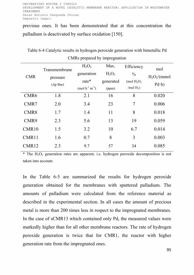
UNIVERSITAT ROVIRA I VIRGILI DEVELOPMENT OF A NOVEL CATALYTIC MEMBRANE REACTOR: APPLICATION IN WASTEWATER TREATMENT Oscar Antonio Osegueda Chicas Depósito legal:
95
previous ones. It has been demonstrated that at this concentration the
palladium is deactivated by surface oxidation [150].
Table 6-4 Catalytic results in hydrogen peroxide generation with bimetallic Pd
CMRs prepared by impregnation
CMR
Transmembrane
pressure
(∆p Bar)
H2O2
generation
rate*
(mol h-1 m-2)
Max.
H2O2
generated
(ppm)
Efficiency
%
(mol H2O2
/mol H2)
mol
H2O2/(mmol
Pd·h)
CMR6 1.8 2.1 16 8 0.020
CMR7 2.0 3.4 23 7 0.006
CMR8 1.7 1.4 11 8 0.018
CMR9 2.3 5.6 13 19 0.059
CMR10 1.5 3.2 10 6.7 0.014
CMR11 1.6 0.7 8 3 0.003
CMR12 2.3 9.7 57 34 0.085
* The H2O2 generation rates are apparent, i.e. hydrogen peroxide decomposition is not
taken into account.
In the Table 6-5 are summarized the results for hydrogen peroxide
generation obtained for the membranes with sputtered palladium. The
amounts of palladium were calculated from the reference material as
described in the experimental section. In all cases the amount of precious
metal is more than 200 times less in respect to the impregnated membranes.
In the case of sCMR13 which contained only Pd, the measured values were
markedly higher than for all other membrane reactors. The rate of hydrogen
peroxide generation is twice that for CMR1, the reactor with higher
generation rate from the impregnated ones.

UNIVERSITAT ROVIRA I VIRGILI DEVELOPMENT OF A NOVEL CATALYTIC MEMBRANE REACTOR: APPLICATION IN WASTEWATER TREATMENT Oscar Antonio Osegueda Chicas Depósito legal:
96
The rest of the palladium sputtered membrane reactors present quite similar
results to those for the impregnated ones. This is an indication that the main
part of the palladium in the impregnated membranes is not involved in the
reaction. The main role of the noble metal in the studied reaction is the
hydrogen activation that occurs on the metallic surface. A very high degree
of metal dispersion is achieved in the sputtered membranes, that is
translated into very high activity for hydrogen peroxide generation
compared to the impregnated membranes. In the last column of Table 6-5
the activities for hydrogen peroxide generation are normalized with respect
to the palladium content. A comparison between CMR2 and sCMR13 (both
of them with the same 20 nm pore size supporting membrane) shows a very
significant difference: the sputtered membrane has almost 1500 times higher
activity. In all other cases there are large differences as well. The second
active phases for sputtered membranes were the same as for the impregnated
ones. TiO2 was not used due to its very low activity in the studied oxidation
reaction as discussed in the next sections. The interference that these second
phases could have on the results reported in Table 6-5 is unknown at this
stage.

UNIVERSITAT ROVIRA I VIRGILI DEVELOPMENT OF A NOVEL CATALYTIC MEMBRANE REACTOR: APPLICATION IN WASTEWATER TREATMENT Oscar Antonio Osegueda Chicas Depósito legal:
97
Table 6-5 Summarized results obtained for the different catalytic membrane
reactors in the hydrogen peroxide generation
CMR
Transmembrane
pressure
(∆P Bar)
H2O2
generation
rate*
(mol h-1 m-2)
Max.
H2O2
generated
(ppm)
Efficiency
%
(mol H2O2
/mol H2)
mol
H2O2/(mm
ol Pd·h)
sCMR13 4.5 13.7 70 64 50.184
sCMR14 2.3 3.0 14 13 4.640
sCMR15 1.2 1.9 16 8 1.465
sCMR16 2.3 0.6 3 2 7.326
sCMR17 2.6 2.2 19 9.4 5.373 * The H2O2 generation rates are apparent, i.e. hydrogen peroxide decomposition is not
taken into account.
Once the maximum level of hydrogen peroxide in the solution was reached
the Pd sputtered membrane reactors were deactivated as in the case of the
impregnated ones. It is reasonable to suppose that the deactivation is due to
the surface oxidation of Pd similarly to the impregnated membranes. This
process is probably even faster due to the higher dispersion of palladium
and minimum size of Pd particles. Following this considerations the reactors
should be easily re-activated in contact with hydrogen as in the previous
case. Surprisingly after applying this simple procedure of hydrogen flowing
through the membranes they were not active in the studied reaction. The
membranes were reduced by flowing hydrogen in a continuous reactor at
different temperatures, up to 400 ºC. The cooling step was performed by
hydrogen or an inert gas. In both cases the membranes remained inactive
after this procedure. In order to re-activate the membranes it was necessary
to calcine in air at 400 ºC, reduce by hydrogen at 400 ºC and cool them in an

UNIVERSITAT ROVIRA I VIRGILI DEVELOPMENT OF A NOVEL CATALYTIC MEMBRANE REACTOR: APPLICATION IN WASTEWATER TREATMENT Oscar Antonio Osegueda Chicas Depósito legal:
98
inert atmosphere. Thereafter the membranes presented exactly the same
activities for hydrogen peroxide generation. All experiments were carried
out in MilliQ water; no chemicals have been added to the experimental
setup except the high purity hydrogen and air. Chemical contaminants that
require oxidation were discarded as a possible cause for the deactivation.
These results suggest that, in addition to the surface passivation of the
palladium, there are additional changes in the noble metal. In may be
assumed that hydrogen has an additional effect which is difficult to clarify
by directly investigating the membrane reactors. We discuss this issue in the
section where temperature programmed desorption results for palladium
sputtered on corundum powder are presented.
6.5.2 Phenol oxidation with catalytic membrane reactors prepared by
impregnation
The catalytic membrane reactors with only palladium as active phase
(CMR1 to CMR5) did not present any appreciable activity in the phenol
oxidation reaction. Figure 6-24 presents the results for CMR1 at different
reaction temperatures. Additionally, the results for a blank test, CMR18 (no
active phase), are included. In this case the experimental conditions were
maintained and the test was performed in order to verify if any stripping of
the phenol occurs at the reaction temperature. It can be seen that the
concentration of phenol decreases about 5% in 8 hours at both temperatures.
This value is quite similar to the result of the blank test so the apparent
activity can be attributed to the phenol stripping.
These results clearly indicate that in the studied case the palladium is not
active in the reaction of generation of hydroxyl radicals. They also confirm
that the most likely reaction pathway consists of hydrogen activation on Pd
UNIVERSITAT ROVIRA I VIRGILI DEVELOPMENT OF A NOVEL CATALYTIC MEMBRANE REACTOR: APPLICATION IN WASTEWATER TREATMENT Oscar Antonio Osegueda Chicas Depósito legal:
99
surface followed by a reaction between oxygen and activated hydrogen to
form hydrogen peroxide or water. In this case the palladium becomes
deactivated when certain peroxide concentration is reached. A second active
phase in the membrane reactors is needed in order to generate hydroxyl
radicals active in the further oxidation of organic matter present in the
water. This reaction should be faster than the peroxide generation itself in
order to protect the palladium. The validity of the above statement was
checked by a simple experiment. Previous to the insertion of the membrane
reactor in the reaction vessel, a Fe2+ salt had been added to the phenol
solution. The results for the CMR1 are presented in Figure 6-24. As can be
seen the phenol concentration decreases by about 40% within 8 h of
reaction. In the presented case the phenol elimination coincides with the
TOC and COD decrease. It is important to note that the results of the phenol
elimination depend linearly on time. This suggests a first-order reaction with
respect to hydrogen peroxide generation, e.g. the phenol oxidation is the
faster reaction.

UNIVERSITAT ROVIRA I VIRGILI DEVELOPMENT OF A NOVEL CATALYTIC MEMBRANE REACTOR: APPLICATION IN WASTEWATER TREATMENT Oscar Antonio Osegueda Chicas Depósito legal:
100
0 2 4 6 8
60
70
80
90
100
CMR1 at 40C CMR1 at 60C CMR1 at 60C and Fe2+ CMR18
Phe
nol C
once
ntra
tion
(% C
/Co)
Time (h)
Figure 6-24 Phenol oxidation with CMR1
The calculated rate of phenol oxidation is 0.05 mmol h-1 assuming a linear
dependence in the case of CMR1 in the presence of Fe2+. The normalized
value for hydrogen peroxide generation for the CMR1 presented in Table
6-2 is 6.7 mol H2O2 (h m2)-1 which corresponds to 5.5 mmol h-1·reactor-1. A
comparison of these values suggests that about 10-15% of the generated
peroxide is directly involved in the organic oxidation. The results therefore
are not very far from the recommended conditions for the Fenton reaction
where usually an oxidant excess of about 3-5 times with respect to the
organic matter is considered [163]. The efficiency is calculated as:

UNIVERSITAT ROVIRA I VIRGILI DEVELOPMENT OF A NOVEL CATALYTIC MEMBRANE REACTOR: APPLICATION IN WASTEWATER TREATMENT Oscar Antonio Osegueda Chicas Depósito legal:
101
∗ 100 (1)
14 → 6 17 (2)
where H2O2r is the required hydrogen peroxide to achieve complete
mineralization of phenol and H2O2p is the theoretical amount of hydrogen
peroxide generated with the catalytic membrane reactor using the kinetic
rate calculated for every CMR.
As mentioned before, the experiments performed with CMR1 to CMR5
demonstrate that the presence of a second active phase in the reactors is
required to ensure catalytic activity in the Fenton reaction.
Different heterogeneous active phases are reported in the literature to be
active in the reaction of hydroxyl radical generation from hydrogen peroxide
[96]. In the present study we chose Fe2O3, CuAl2O4, TiO2 and CeO2.
Figure 6-25 presents the results for the phenol oxidation when the catalytic
membrane reactors with second active phases CuAl2O4 (CMR6), CeO2
(CMR7), Fe2O3 (CMR8) and TiO2 (CMR9) were used. Despite the high
activity of CMR9 for hydrogen peroxide generation, no detectable activity
was observed for phenol oxidation. The results indicate that TiO2 in this
case is not active in generating hydroxyl radicals that subsequently would
oxidize the phenol. More detailed studies should be performed in order to
elaborate a plausible explanation in this particulate case.
As seen in Figure 6-25, 15% of phenol elimination was reached with
CMR6. The phenol mineralization monitored by TOC analysis was 5%. In
this case no aromatic compounds were detected as intermediates in the
HPLC chromatograms, and all signals detected corresponded to low
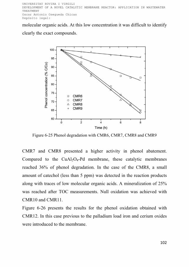
UNIVERSITAT ROVIRA I VIRGILI DEVELOPMENT OF A NOVEL CATALYTIC MEMBRANE REACTOR: APPLICATION IN WASTEWATER TREATMENT Oscar Antonio Osegueda Chicas Depósito legal:
102
molecular organic acids. At this low concentration it was difficult to identify
clearly the exact compounds.
Figure 6-25 Phenol degradation with CMR6, CMR7, CMR8 and CMR9
CMR7 and CMR8 presented a higher activity in phenol abatement.
Compared to the CuAl2O4-Pd membrane, these catalytic membranes
reached 36% of phenol degradation. In the case of the CMR8, a small
amount of catechol (less than 5 ppm) was detected in the reaction products
along with traces of low molecular organic acids. A mineralization of 25%
was reached after TOC measurements. Null oxidation was achieved with
CMR10 and CMR11.
Figure 6-26 presents the results for the phenol oxidation obtained with
CMR12. In this case previous to the palladium load iron and cerium oxides
were introduced to the membrane.

UNIVERSITAT ROVIRA I VIRGILI DEVELOPMENT OF A NOVEL CATALYTIC MEMBRANE REACTOR: APPLICATION IN WASTEWATER TREATMENT Oscar Antonio Osegueda Chicas Depósito legal:
103
The CMR catalytic redox properties are improved by the interaction
between metallic palladium and cerium oxide, since the oxygen storage
capacity of cerium oxide provides oxygen mobility in the membrane active
phase [91]. In addition, E.G. Heckert et al have observed that cerium oxide
redox capacity (Ce3+ - Ce4+) enhances the catalytic activity of cerium oxide
to act like a hydroxyl radicals generator from hydrogen peroxide [164]. The
analogous Fenton/ Haber Weiss reaction with cerium oxide are:
→ ∙ (3)
∙ → (4)
→ (5)
The reaction temperature was maintained at 60ºC. This catalytic membrane
reactor shows a high activity in phenol degradation, with a phenol
abatement level of 93% after 7 hours of reaction. No intermediates were
detected in the analyzed samples by HPLC. The phenol was oxidized to
carbon dioxide and water. This complete mineralization was confirmed by
the TOC analyses of the samples as well as COD measurements. As in the
previous cases the phenol oxidation is a first order reaction with respect to
peroxide generation. In this case the efficiency of the hydrogen peroxide for
phenol oxidation is about 35%. This value was calculated as in the previous
case and the ratio between phenol elimination (0.13 mmol h-1) to the
peroxide generation for CMR12 from Table 6-4 is 5.5 mmol h-1·reactor-1.

UNIVERSITAT ROVIRA I VIRGILI DEVELOPMENT OF A NOVEL CATALYTIC MEMBRANE REACTOR: APPLICATION IN WASTEWATER TREATMENT Oscar Antonio Osegueda Chicas Depósito legal:
104
0 2 4 6 8
0
20
40
60
80
100
1st run 2nd run 3rd run
Phe
nol c
once
ntra
tion
(% C
/Co)
Time (h)
Figure 6-26 Catalytic phenol oxidation with a Pd-CeO2-Fe2O3 membrane reactor
Once the reaction had finished, the phenol solution in the reaction vessel
was renewed. As it can be seen from the experimental results presented in
Figure 6-26, the results obtained in the second run are the same as those in
the first one. Several consecutive tests have been performed without any
appreciable loss of catalytic activity. This is a very important feature of the
developed membrane reactors that indicates that they can be used in a
continuous operation.
In the open scientific literature there are reports dealing in phenol
hydrogenation using palladium as a catalyst [132, 165-167]. Under the
experimental conditions of the present work we did not expect a similar
reaction, but nevertheless a test was performed. CMR12 was used to
determine possible phenol hydrogenation, and the experimental conditions
were kept constant without air supply to the reaction vessel. No decrease in
the phenol concentration was observed after 5 hours of reaction.

UNIVERSITAT ROVIRA I VIRGILI DEVELOPMENT OF A NOVEL CATALYTIC MEMBRANE REACTOR: APPLICATION IN WASTEWATER TREATMENT Oscar Antonio Osegueda Chicas Depósito legal:
105
6.5.3 Phenol oxidation with catalytic membrane reactors prepared by
sputtering method
The sputtering preparation techniques were aimed at reducing the amount of
precious metal. Very high dispersion is achieved at the same time which
also led to higher overall activity. The proposed method also allows the
deposition of the Pd exclusively into the reaction zone of the studied
reaction.
sCMR13 that contains only Pd as an active phase showed a similar behavior
in the studied reaction as the Pd impregnated membrane reactors. sCMR13
did not present any activity for the phenol oxidation under the studied
conditions. Similarly to the case of the impregnated membrane, Fe2+ salt
was added to the phenol solution previous to the reaction. The presence of
ferrous ions in the homogeneous phase improves the phenol oxidation up to
12% conversion. This value is very low considering the high activity of this
reactor in peroxide generation (Table 6-5). Initially it was deduced that due
to the high rate of hydrogen peroxide generation the oxidant was not
consumed sufficiently fast in the phenol oxidation which would lead to
peroxide accumulation in the solution resulting in palladium deactivation.
Additional experiments presented below revealed that other reactions are
involved in the palladium deactivation.
The surface passivation of Pd due to the slow decomposition of hydrogen
peroxide to reactive hydroxyl radicals may induce the oxidation of the
palladium surface and subsequent deactivation, as it was observed in the
H2O2 generation by V.R. Choudhary et al [168].
The rest of sCMRs were also tested for phenol degradation. Figure 6-27
shows the phenol abatement using these catalytic membrane reactors. The
phenol reduction with sCMR15 and sCMR16 reached 15% after 8 h of
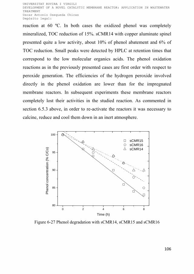
UNIVERSITAT ROVIRA I VIRGILI DEVELOPMENT OF A NOVEL CATALYTIC MEMBRANE REACTOR: APPLICATION IN WASTEWATER TREATMENT Oscar Antonio Osegueda Chicas Depósito legal:
106
reaction at 60 ºC. In both cases the oxidized phenol was completely
mineralized, TOC reduction of 15%. sCMR14 with copper aluminate spinel
presented quite a low activity, about 10% of phenol abatement and 6% of
TOC reduction. Small peaks were detected by HPLC at retention times that
correspond to the low molecular organics acids. The phenol oxidation
reactions as in the previously presented cases are first order with respect to
peroxide generation. The efficiencies of the hydrogen peroxide involved
directly in the phenol oxidation are lower than for the impregnated
membrane reactors. In subsequent experiments these membrane reactors
completely lost their activities in the studied reaction. As commented in
section 6.5.3 above, in order to re-activate the reactors it was necessary to
calcine, reduce and cool them down in an inert atmosphere.
0 2 4 6 880
85
90
95
100
sCMR15 sCMR16 sCMR14
Phe
nol c
once
ntra
tion
(% C
/Co)
Time (h)
Figure 6-27 Phenol degradation with sCMR14, sCMR15 and sCMR16

UNIVERSITAT ROVIRA I VIRGILI DEVELOPMENT OF A NOVEL CATALYTIC MEMBRANE REACTOR: APPLICATION IN WASTEWATER TREATMENT Oscar Antonio Osegueda Chicas Depósito legal:
107
The activity for phenol elimination obtained for sCMR17 is presented in
Figure 6-28.
Figure 6-28 Phenol oxidation using sCMR17 at 60 °C and consecutive runs
In the first test sCMR17 presented 42% of phenol elimination and no
intermediate products were detected (TOC reduction of 42% was observed).
Consequently, a second test was performed after changing the phenol
solution in the reaction vessel. In this case the activity of the membrane
reactor dropped to 18% for phenol degradation and 10% for TOC
elimination. In the third consecutive experiment negligible activity was
obtained and for both measured parameters, phenol and TOC, about 10% of
reduction was obtained. As commented before it was assumed that this
decrease of activity is mainly due to the Pd deactivation. Taking into
account the high dispersion of the Pd within the reaction zone it can be
assumed that the hydrogen peroxide generation rate is significantly higher

UNIVERSITAT ROVIRA I VIRGILI DEVELOPMENT OF A NOVEL CATALYTIC MEMBRANE REACTOR: APPLICATION IN WASTEWATER TREATMENT Oscar Antonio Osegueda Chicas Depósito legal:
108
than the consumption of the oxidant in the subsequent reaction of phenol
oxidation thus leading to increased levels of peroxide which passivates the
noble metal. If this assumption is true, then the Pd activity in the studied
reaction should be recovered after reduction in a hydrogen flow. However,
after the reduction step at 400 ºC in flowing hydrogen followed by a cooling
step under inert atmosphere, the activity for the phenol oxidation barely
reached 20%. The membrane reactor has been calcined and reduced again at
the same conditions. In the experiment performed afterwards Fe2+ salt has
been added to the reactor vessel. In this case the activity for phenol
oxidation was similar to the first run, 40% of phenol elimination. However
the TOC reduction was about 15% that indicates that with the addition of
the homogeneous catalyst the reaction pathways are different. Small
amounts of aromatic type compounds as well as low molecular acids have
been detected as intermediates by HPLC analyses.
The membrane reactor has been calcined in air atmosphere at 400 ºC and
thereafter reduced in H2 flow at 400 ºC, the cooling step was done in inert
gas flow. As it can be seen from Figure 6-28, the activity was recovered
completely.
Some additional experiments with sCMR17 for phenol oxidation at
temperature of 80 ºC were carried out. Increasing the reaction temperature is
expected to enhance the rate of hydrogen peroxide consumption in the
oxidation reaction whilst decreasing the probability of palladium
deactivation by the excess of reagent. The results are presented in Figure
6-29. Before this, the membrane reactor was calcined and reduced as
described above.

UNIVERSITAT ROVIRA I VIRGILI DEVELOPMENT OF A NOVEL CATALYTIC MEMBRANE REACTOR: APPLICATION IN WASTEWATER TREATMENT Oscar Antonio Osegueda Chicas Depósito legal:
109
0 2 4 6 8
20
30
40
50
60
70
80
90
100
1st run 2nd run
Phe
nol c
once
ntra
tion
(%
C/C
o)
Time (h)
Figure 6-29 Phenol oxidation using sCMR17 at 80 °C
As seen in Figure 6-29, 74% of phenol oxidation was reached in the first
run. No intermediate products were detected by HPLC which was also
confirmed by the TOC measurements - 74% elimination. However in the
second run the activities dropped more than twice, 36% of phenol oxidation.
The final TOC of the solution was reduced with 25%, low molecular
organic acids were detected by HPLC analyses.
Despite the high activities for hydrogen peroxide generation of the Pd
sputtered membrane reactors compared to the impregnated ones there are
some specific reactions which take place in the former case leading to the
rapid deactivation of the reactors. The small size of the palladium particles
obtained after sputtering increases their activity but at the same time makes
them more vulnerable to undesired reaction, e.g. palladium hydride
formation.
UNIVERSITAT ROVIRA I VIRGILI DEVELOPMENT OF A NOVEL CATALYTIC MEMBRANE REACTOR: APPLICATION IN WASTEWATER TREATMENT Oscar Antonio Osegueda Chicas Depósito legal:
110
It is important to mention that when the second active phase is cerium oxide
the membrane reactor appears to have a more stable activity compared to the
other ones. A possible explanation for this difference could be the specific
interaction between the small palladium crystals and the surrounding ceria
which can favor the stabilization of the metal [169-173]. Possible
implications of this strong metal support interaction (SMSI) in the studied
reaction are being investigated in a more detail.
The formation of palladium hydride is an important concern in the dense Pd
membrane when used in gas mixtures separation or in hydrogenation
reactions [174-175]. Its formation provokes mechanical damage of the
membranes, they become brittle. In order to overcome the problems
associated with the hydride formation the working temperature is
maintained above certain level, e.g. 300 ºC [176-177].
In the Pd assisted catalytic reactions, especially in hydrogenation processes,
the formation of palladium hydride is not considered as a major factor that
can alter the catalyst activity; on the contrary, in some studies it is
considered a beneficial source of hydrogen [178-179]. Other authors suggest
that the palladium hydride, especially after it is transformed to ß-Pd, is a
main cause for the Pd deactivation, e.g. in hydrogenation reactions [180-
181].
Generally the palladium deactivation is attributed to other undesired
reactions such as coke formation, water condensation, sulphur and carbon
monoxide presence [96, 182].
According to works in the open scientific literature the absorption of
hydrogen leads after some time to Pd phase change, the α-Pd to ß-Pd. Some
reports suggest that ß-Pd (PdHx with x > 0.5), once is formed is not active
for hydrogen activation [180]. This consideration could explain the fast

UNIVERSITAT ROVIRA I VIRGILI DEVELOPMENT OF A NOVEL CATALYTIC MEMBRANE REACTOR: APPLICATION IN WASTEWATER TREATMENT Oscar Antonio Osegueda Chicas Depósito legal:
111
deactivation of the membrane reactors with palladium loaded by sputtering.
In the present case this process may be highly facilitated due to the high
surface/bulk ratio. This process should be reversible according to the current
scientific understanding.
6.5.4 Effect of hydrogen on sputtered palladium nanoparticles
Some simple experiments were carried out in order to investigate the effects
of hydrogen on the sputtered palladium nanoparticles. Corundum powder
with sputtered palladium described in the previous sections was used. It was
tested in TPD equipment coupled to a mass detector. A cycle program was
developed that attempted to achieve the reaction conditions of the hydrogen
peroxide generation tests as well as the activation procedure after
deactivation. The different steps as well as their purpose are presented in
Table 6-6.
Table 6-6 TPD program and the aim of each step
Step T, gas flows, time Aim of the step
1 60 ºC, 20 sccm3 min-1, 5% H2 in Ar, 2 h
Reduction of the Pd, possible formation of ß-Pd
2 60 ºC, 20 sccm3 min-1, Ar, 30 min
Purging the lines
3 Heating ramp, 5 ºC min-1 up to 400 ºC, 30
min at 400 ºC; 20 sccm3 min-1, Ar
Desorption of the H2 from the ß-Pd
4 Cool down to 60 ºC in 20 sccm3 min-1, Ar
Restore the initial state of the studied sample

UNIVERSITAT ROVIRA I VIRGILI DEVELOPMENT OF A NOVEL CATALYTIC MEMBRANE REACTOR: APPLICATION IN WASTEWATER TREATMENT Oscar Antonio Osegueda Chicas Depósito legal:
112
The program was repeated 3 times. Figure 6-30 presents the results from the
mass detector for Pd sputtered on corundum. The different steps as well as
the relevant temperatures are also shown. The y-axis is scaled in a range
where the zone of interest is clearly visualised. It can be seen from the graph
that hydrogen was desorbed at 320 ºC in the first cycle. In the second cycle
the peak that corresponds to hydrogen was almost undetectable. In the third
cycles no hydrogen was detected. The sample was recovered and calcined at
400 ºC and subsequently reduced in hydrogen flow and cooled in Ar
atmosphere. This was the activation procedure found to be effective for the
reactivation of Pd sputtered membrane reactors. Subsequently, the TPD
sequence described above was repeated. The results are shown on Figure
6-31. As it can be seen, the mass detector response was exactly the same as
in the first case.
Figure 6-30 TPD-MS m/z = 2 signal obtained from Pd sputtered on corundum

UNIVERSITAT ROVIRA I VIRGILI DEVELOPMENT OF A NOVEL CATALYTIC MEMBRANE REACTOR: APPLICATION IN WASTEWATER TREATMENT Oscar Antonio Osegueda Chicas Depósito legal:
113
These experiments clearly demonstrate that hydrogen is absorbed by the
palladium and probably ß-Pd phase is formed. The absorbed hydrogen is
strongly retained in the metal and is released at 320 ºC. This temperature is
similar to the one reported by other authors [182]. The results also
demonstrate that some transformations of the palladium occur as can be
concluded from its decreasing capacity for hydrogen storage. It is difficult to
offer a plausible explanation of this observation at this stage.
Figure 6-31 TPD-MS m/z = 2 signal obtained from reactivated Pd-corundum
Palladium nanoparticles with defined sizes (4-6 nm) have been studied at
different temperatures in various environments e.g. air, inert gas, hydrogen
in [182]. The metal particles have been observed by HRTEM and selected
area electron diffraction (SAED). These authors observed loss of
cristallinity of the metal lattice especially when Pd was in a hydrogen

UNIVERSITAT ROVIRA I VIRGILI DEVELOPMENT OF A NOVEL CATALYTIC MEMBRANE REACTOR: APPLICATION IN WASTEWATER TREATMENT Oscar Antonio Osegueda Chicas Depósito legal:
114
atmosphere. This finding was attributed to the metal support interactions
occurring at high temperature.
We discard the possibility that the palladium deactivation observed with the
catalytic membrane reactors is due to the interaction between the Pd and the
support especially taking into account that it occurs at 60 ºC.
In other study [183] similar experiments demonstrate that at 100 ºC under
hydrogen the Pd core/ Pt shell 4nm nanoparticles are completely reordered
leading to formation of homogeneous Pd-Pt alloy (called solution by the
authors).
A more extended study is underway in our laboratory in order to better
understand the mechanisms involved in the palladium deactivation. In case
we are able to confirm that the hydrogen plays a major role in the metal
deactivation, especially for particles in the nanoscale range, additional steps
will be considered for its stabilization without decreasing its activity for the
hydrogen activation.
6.6 Catalytic activity of CMRs in continuous system
Some experiments in continuous mode were conducted with our proposed
module reactor. The designed system was evaluated in continuous operation
in catalytic reduction of water contaminants. Pd-CeO2 CuAl2O4 and Pd-
CeO2-Fe2O3 membrane reactors were selected and used in the selective
reduction of nitrates and hydrodechlorination of chlorinated organic
compounds. The active phases were chosen according to the literature.
6.6.1 Selective reduction of nitrates
The selected 30 cm length membrane reactor was placed in the metal
housing. The nitrates solution (100ppm) was fed to the lumen side of the

UNIVERSITAT ROVIRA I VIRGILI DEVELOPMENT OF A NOVEL CATALYTIC MEMBRANE REACTOR: APPLICATION IN WASTEWATER TREATMENT Oscar Antonio Osegueda Chicas Depósito legal:
115
membrane reactor. Whereas, H2 was continuously dosed through the shell
side. Also, one experiment was carried out introducing H2 co-currently with
the nitrate solution feed. The catalytic activity of the CMRs was evaluated
in a single pass mode. The results are shown in the Table 6-7 after a mass
balance in the outlet solution. The catalytic activity was stable up to 8 hour
of operation.
The NO3- conversion was calculated with the following equation:
100 %
The results show an appreciative catalytic activity using the Pd cupper
spinel membrane. As it can be observed from the Table 6-7, an important
factor in the operation of the CMRs in continuous mode is the correcting
dosing of the gas phase. In the experimental runs 1 and 2, once the H2 flow
was increased from 6 to 10 NmL min-1 the nitrate conversion is 6.5 times
lower. This fall in the conversion is attributed to a blowing effect of the gas
phase. When the H2 is dosed up to certain values the gas phase blows the
liquid from the CMR surface. It is important to notice that when working
above the bubble pressure point and introducing a large amount of gas it is
mainly loss. At the same time the gas displaces the liquid from the reaction
zone e.g. the active phase loaded onto the membrane. Similar effect is also
commented by K. Duab et al. They attributed the low catalytic activity to
the displacement of the liquid-gas boundary from the catalyst surface [184].

UNIVERSITAT ROVIRA I VIRGILI DEVELOPMENT OF A NOVEL CATALYTIC MEMBRANE REACTOR: APPLICATION IN WASTEWATER TREATMENT Oscar Antonio Osegueda Chicas Depósito legal:
116
Table 6-7 Selective reduction of nitrates with CMRs under continuous operation regimen
Exp H2
(NmL min-1)
NO3-
(ppm)
NH4+
(ppm)
NO2-
(ppm)
NO3-
Conversion
(%)
Selectivity
N2
(%)
1(1) 6 14 6 <0.03 86 76
2(1) 10 87 1 <0.03 13 73.5
3(2) 6 94 <0.03 <0.03 6 100
4(3) 6 74 6.5 <0.03 16 13.9
5(3) 10 98 <0.03 <0003 2 100 (1)The experiments were carried out using the Pd-CeO2 membrane reactor. (2) H2 was dosed through the membrane wall. (3)H2 was dosed co-currently with the nitrate solution feed. (4-5)Experimental results obtained using the Pd-CeO2-Fe2O3 membrane reactor
An important issue related with results is the selectivity to N2 as final
product. Despite the high nitrates conversion of 86% was achieved, an
undesirable reaction took place in the CMR. Ammonia was detected in the
outlet stream. The NH4+ concentration rises up to 6 ppm in the first
experimental run, which has a higher toxic effect to human health. The
nitrite concentration was below of the detection limit in all experimental
runs.
A third experimental run was carried out using the same CMR. This time H2
was co introduced to the lumen side of the membrane reactor. Under this
operative condition, the nitrate conversion was 14 times lower compared
with the first run. The low activity can be related with the low solubility of
the H2 at these working conditions. O.M. Illitch et al. and N. Wehbe et al.
reported experimental results operating their CMR in a flow through mode
UNIVERSITAT ROVIRA I VIRGILI DEVELOPMENT OF A NOVEL CATALYTIC MEMBRANE REACTOR: APPLICATION IN WASTEWATER TREATMENT Oscar Antonio Osegueda Chicas Depósito legal:
117
[185, 149]. In both cases the nitrates solution was pumped to the lumen of
the membrane reactor. And the hydrogen was previously dosed to the
solution in order to dissolve the maximum amount of the gas in the liquid.
However, they reported diffusion limitations and an elevated generation of
ammonia.
The Pd-CeO2-Fe2O3 membrane reactor presents a low catalytic activity in
the reduction of nitrates as well a low selectivity to N2. Almost null activity
was observed operating this membrane reactor at 10 NmL min-1. N.
Barrabés et al. have reported higher activities in NO3- reduction using
supported CeO2 and Pt-CeO2 [186]. A more detailed study has to be carried
out in order to find the optimal conditions.
Consecutive tests have been performed with the Pd/ CeO2 membrane
reactor. The CMR was operated up to 4 times at the same conditions in the
first experimental run (Table 6-7). Between each test, the CMR was
previously dried with flowing H2 at room temperature. The individual tests
have been performed during 8 h as commented before. No changes in the
activities were observed between the tests.
As we can observe, our experimental results are similar from the reported in
the literature. As initially proposed, the obtained results validate the
designed module reactor for continuous operation mode. In order to improve
the results it must be optimised the catalytic active phases loaded onto the
membrane. The catalyst screening could be done by using the batch system
described in the experimental section.
6.6.2 Hydrodechlorination of chlorinated aromatic compounds
Another experiment was carried out in the metal housing reactor. The Pd-
CeO2-Fe2O3 membrane reactor was used in the hydrodechlorination of 4-Cl-

UNIVERSITAT ROVIRA I VIRGILI DEVELOPMENT OF A NOVEL CATALYTIC MEMBRANE REACTOR: APPLICATION IN WASTEWATER TREATMENT Oscar Antonio Osegueda Chicas Depósito legal:
118
phenol. A mixture of 4-Cl-phenol and formic acid was fed to the lumen side
of the membrane reactor. The formic acid was used as hydrogen donor as it
was previously reported by F.D. Kopinke et al. [144]. As they reported,
supported Pd cluster are active in the catalytic decomposition of formic acid
to H2 and CO2. The hydrogen is chemisorbed and dissociated in the surface
of the noble metal.
The module was operated as single pass mode in 24 hours test. The results
are shown in the Figure 6-32.
Figure 6-32 Hydrodechlorination of 4-Cl-phenol with CMR in continuous mode
The conversion of 4-Cl-phenol to phenol achieve up to 40% with the
catalytic membrane reactor. The CMR presented steady state activity in the
hydrodechlorination process during the first 11 h. However, after this time
the activity started to decrease up to almost null conversion at the end of the
test (24 h). The experiment demonstrates that the proposed mode of

UNIVERSITAT ROVIRA I VIRGILI DEVELOPMENT OF A NOVEL CATALYTIC MEMBRANE REACTOR: APPLICATION IN WASTEWATER TREATMENT Oscar Antonio Osegueda Chicas Depósito legal:
119
operation of the CMR can be successfully used in this kind of processes. In
order to improve the stability of the catalyst more investigation should be
done. From the literature the deactivation of the catalyst is attributed to two
main causes: i) oxidation of the Pd surface under acid condition. Although
the formic acid is used as hydrogen donor, also it can induce the oxidation
of the catalyst. Pd+2 is not active in the catalytic decomposition of the formic
acid. And ii) Cl- induce the poisoning of the Pd particles [144].
Another experiment was carried out in order to determine if the point i),
palladium oxidation, is the cause of deactivation. In this experiment a
formic acid solution was fed to the lumen of the CMR. The catalytic
decomposition of the acid was monitored measuring TOC in the outlet
stream. During the first 2 hours, the TOC decreased with 20% in the outlet
feed. After this time, no formic acid decomposition was detected. Therefore,
4-Cl-phenol was injected to the feeding solution to observe if the
hydrodechlorination reaction is reactivated. The outlet was constantly
monitored but phenol was not detected. At this moment, more tests have
been planned to determine the poisoning effect of the chloride to Pd
particles.
Even though these results are not concluding, they open a path to operate
our CMR with a wide variety of hydrogen sources. In the same way, the
metal housing provides different configuration to be explored in the use of
the membrane reactors.

UNIVERSITAT ROVIRA I VIRGILI DEVELOPMENT OF A NOVEL CATALYTIC MEMBRANE REACTOR: APPLICATION IN WASTEWATER TREATMENT Oscar Antonio Osegueda Chicas Depósito legal:
120

UNIVERSITAT ROVIRA I VIRGILI DEVELOPMENT OF A NOVEL CATALYTIC MEMBRANE REACTOR: APPLICATION IN WASTEWATER TREATMENT Oscar Antonio Osegueda Chicas Depósito legal:
121
Chapter 7. Conclusions
Different catalytic membrane reactors were successfully prepared to be used
in a novel approach to treat water pollutants. In this work they were tested
with model compound solutions in laboratory controlled conditions.
Commercial ultra and nanofiltration ceramic hollow fibers were chosen as
support in the preparation of the CMRs. The fibers are made from α-Al2O3,
material highly resistant to severe conditions e.g. pH range from 1 to 14,
broad temperature tolerance, large transmembrane pressure differences,
chemical inertness. They resulted to be an exceptional support for the active
phases loaded across the membrane wall or on the membrane surface.
The palladium has been chosen as the most appropriated active phase for the
hydrogen peroxide generation due to its capability for hydrogen activating.
Two methods were successfully developed to incorporate palladium into the
membranes: i) firstly the noble metal has been incorporated into the
membranes by means of impregnation methods starting from precursor
solutions, and ii) the second method is a novel procedure based on
sputtering technique for selectively loading of the Pd on the CMRs. This
method allowed us to locate the palladium on the external surface of the
membrane reactor where the reactions take place. As well, the amount of the
noble metal was reduced up to 260 times compared with the impregnation
method.
Electronic microscopy techniques and XRD analysis confirmed a
homogeneous distribution of the active phases through the membrane wall
and external surface of the CMRs prepare by impregnation. Pd cluster with

UNIVERSITAT ROVIRA I VIRGILI DEVELOPMENT OF A NOVEL CATALYTIC MEMBRANE REACTOR: APPLICATION IN WASTEWATER TREATMENT Oscar Antonio Osegueda Chicas Depósito legal:
122
sizes from 19 to 31 nm were identified along the entire membrane reactor.
The cluster sizes are related with the voids in the membrane wall.
HRTEM was selected to observe the sputtered Pd particles. The mean
particle size of Pd particles is centered at 4.8 nm, being 95% of particles
within the 2-7 nm range. Also, a micro elemental analysis has shown a
selective deposition of Pd particles on the surface on the CMR.
The developed preliminary studies demonstrated that the most efficient
method for the hydrogen peroxide generation consist in a controlled dosing
of the hydrogen to the inner part of the membrane reactor meanwhile the
oxygen is supplied by bubbling air in the water solution. In order to screen
the prepared catalytic membrane reactors simple semi batch equipment has
been designed and assembled.
The prepared Pd based membrane reactors have been characterized by the
following parameters: hydrogen peroxide generation rate per reactor area or
metal load, maximum achievable hydrogen peroxide concentration and
selectivity to the hydrogen peroxide with respect to the dosed hydrogen.
The monometallic and bimetallic catalytic membrane reactors were
successfully tested in the generation of hydrogen peroxide in our
experimental design in batch mode. The results have shown a high activity
to generate hydrogen peroxide with the monometallic Pd membrane
reactors. In the case of the sCMR13 (sputtered Pd) showed the higher
activity 13.7 mol H2O2 h-1 m-2. As we observed, the activity was
intrinsically related with the size of the Pd phase. At lowest particle size
higher was the activity in the generation of H2O2. The highest activity in the
H2O2 generation with the Pd impregnated membranes was obtained with
CMR12: 9.7 mol H2O2 h-1 m-2.

UNIVERSITAT ROVIRA I VIRGILI DEVELOPMENT OF A NOVEL CATALYTIC MEMBRANE REACTOR: APPLICATION IN WASTEWATER TREATMENT Oscar Antonio Osegueda Chicas Depósito legal:
123
After normalization of the hydrogen peroxide generation to the amount of
noble metal, the membrane reactors with sputtered Pd have almost 1500
times higher activity that the ones where the Pd was loaded by
impregnation.
It has been shown that when certain concentration of hydrogen peroxide is
reached the Pd becomes inactive in the studied reaction. A plausible
mechanism for the Pd deactivation was proposed that was further confirmed
by the XPS analysis. It has been found that the excess of H2O2 passivate the
Pd surface. The initial activity of the membrane reactors is completely
recovered by flowing hydrogen through the membrane wall at ambient
temperature.
The experiments of phenol oxidation by the in-situ generated H2O2
demonstrate the necessity of the second active phase that is responsible for
the formation of •OH radicals. The results demonstrated that once •OH were
formed the phenol oxidation is very fast thus preventing the Pd passivation
by the excess of H2O2. The bimetallic CMRs with impregnated Pd
demonstrate to be very stable in the oxidation process. No deactivation of
the reactors was observed on stream. The membrane reactors have shown
steady behavior in consecutive tests without decreasing the activity for
phenol oxidation. Roughly, up to 30-40% of the generated hydrogen
peroxide is directly involved in the phenol oxidation reaction. It has been
observed that the transition metal oxide phase plays an important role in the
phenol oxidation route e.g. when CeO2 or mixture CeO2/ Fe2O3 have been
used no intermediate products have been observed.
In both cases, Pd impregnated and Pd sputtered membrane reactors, the ICP
analyses demonstrate no leaching of active phase to the reaction mixture.

UNIVERSITAT ROVIRA I VIRGILI DEVELOPMENT OF A NOVEL CATALYTIC MEMBRANE REACTOR: APPLICATION IN WASTEWATER TREATMENT Oscar Antonio Osegueda Chicas Depósito legal:
124
Despite the very high activities for hydrogen peroxide generation of the
membrane reactors with sputtered palladium they deactivate very fast in the
phenol oxidation reaction. It has been proven that the hydrogen plays a
major role in the loss of catalytic activity. The experimental results with the
sCMRs as well as the TPD and HRTEM analyses of the sputtered Pd on
corundum powder have shown that the tiny Pd particles absorb hydrogen
until they are converted to PdHx with -Pd structure. This process seems
that is highly facilitated by the high surface/ bulk ratio of the sputtered Pd.
The formed -Pd hydride is not active in the hydrogen activation process.
Once it is formed the generation of hydrogen peroxide is stopped. In order
to recover the catalytic activity in the studied reaction it is necessary to
calcine the sCMR followed by activation step. The transition metal oxide
active phase can slow down the process as in the case of CeO2. Additional
studies are strongly encouraged in order to get better understanding of the
observed phenomenon.
The obtained results in the present thesis are very promising and validate the
suitability of the proposed novel approach in terms of oxidation of target
pollutants via in situ generated chemical oxidants.
The developed membrane reactors due to their modular nature are easily
scalable up to process larger amount of effluent.
Concerning to the module reactor, two different reactions were efficiently
carried out in order to determine the feasibility in the operation of the CMRs
in continuous mode. The selective reduction of nitrates and
hydrodechlorination of 4-Cl-phenol were selected as model reactions.

UNIVERSITAT ROVIRA I VIRGILI DEVELOPMENT OF A NOVEL CATALYTIC MEMBRANE REACTOR: APPLICATION IN WASTEWATER TREATMENT Oscar Antonio Osegueda Chicas Depósito legal:
125
The preliminary results in the reduction of nitrates and hydrodechlorination
of 4-Cl-phenol confirm the viability of the module reactor operated in
continuous mode.

UNIVERSITAT ROVIRA I VIRGILI DEVELOPMENT OF A NOVEL CATALYTIC MEMBRANE REACTOR: APPLICATION IN WASTEWATER TREATMENT Oscar Antonio Osegueda Chicas Depósito legal:
127
RFERENCES
[1] United Nation Environmental Programme (UNEP); Global
environmental outlook GEO4 environmental for development,
section B, chapter 4: Water, first edition (2007).
[2] World Health Organization (WHO); Un-water global annual
assessment of sanitation and drinking water (GLAAS) 2010:
targeting resources for better results, first edition (2010).
[3] M. Palaniappan, P.H. Gleick, L. Allen, M.J. Cohen, J.C. Smith, C.
Smith; Clearing the waters, A focus on water quality solutions;
United Nation Environmental Programme (UNEP) (2010), edited by
N. Ross.
[4] World Water Assessment Programme (WWAP); Water in changing
world; United Nation Educational, Scientific and Cultural
Organization (UNESCO), first edition (2009).
[5] R. Dittmeyer, J. Caro; Catalytic membrane reactors from Handbook
of Heterogeneous Catalysis, second edition (2008) Wiley-VCH
International; edited by G. Ertl, H. Knözinger, F. Schüth, J.
Weitkamp.
[6] F. Gallucci, A. Basile, F. Ibney Hai; Introduction – A review of
membrane reactors from Membrane for Membrane Reactors:
Preparation, Optimization and Selection, first edition (2011) John
Willey & Sons; edited by A. Basile, F. Gallucci.
[7] K. Li; Ceramic membranes and membrane processes from Ceramic
Membranes for Separation and Reaction, first edition (2007) John
Willey & Sons; edited by K. Li.

UNIVERSITAT ROVIRA I VIRGILI DEVELOPMENT OF A NOVEL CATALYTIC MEMBRANE REACTOR: APPLICATION IN WASTEWATER TREATMENT Oscar Antonio Osegueda Chicas Depósito legal:
128
[8] A. Basile, F. Gallucci, S. Tosti; Synthesis, characterization, and
applications of palladium membranes from Membrane Science and
Technology, Vol. 13: Inorganic Membranes: Synthesis,
Characterization and Application, first edition (2008) Elsevier;
edited by R. Mallada and M. Menéndez.
[9] G. Barbierie, F. Scura; Fundamental of chemical membrane reactors
from Membrane Operation: Innovative Separations and
Transformations, first edition (2009), Wiley-VCH International;
edited by E. Drioli, L. Giorno.
[10] E. Fontananova, E. Drioli; Catalytic membranes and membrane
reactors from Comprehensive Membrane Science and Membrane
Reactors, Vol. 3: Chemical and Biochemical Transformations in
Membrane Systems, first edition (2010), Elsevier; edited by E.
Drioli, L. Giorno.
[11] E. Drioli, E. Curcio, G. Di Profio; State of art and recent progresses
in membrane contactors; Chemical engineering research and desing
83 (2005) 223-233.
[12] S. Pereira Nunes; Organic – inorganic membranes from Membrane
Science and Technology, Vol. 13: Inorganic Membranes: Synthesis,
Characterization and Applications, first edition (2008), Elsevier,
edited by R. Mallada and M. Menéndez.
[13] A. Buenkenhoudt, A. Kovalevsky, J. Luyten, F. Snijkers; Basic
aspects in inorganic membrane preparation from Comprehensive
Membrane Science and Engineering, Vol. 1: Basic Aspects of
Membrane Science and Engineering, first edition (2010), Elsevier;
edited by E. Drioli, L. Giorno.

UNIVERSITAT ROVIRA I VIRGILI DEVELOPMENT OF A NOVEL CATALYTIC MEMBRANE REACTOR: APPLICATION IN WASTEWATER TREATMENT Oscar Antonio Osegueda Chicas Depósito legal:
129
[14] A.F.Ismail, L.I.B. David; A review on the latest development of
carbon membranes for gas separation; Journal of membrane science
193 (2001) 1-18.
[15] B. Zhang, T. Wang, S. Liu, S. Zhang, J. Qiu, Z. Chen, H. Cheng;
Structure and morphology of microporous carbon membrane
materials derived from poly(phthalazinone ether sulfone ketene);
Microporous and mesoporous materials 96 (2006) 79-83.
[16] C. Telléz, M. Menéndez; Zeolite membrane reactors from
Membrane for Membrane Reactors: Preparation, Optimization and
Selection, first edition (2011) John Willey & Sons; edited by A.
Basile, F. Gallucci.
[17] E.E. McLeary, J.C. Jansen, F. Kapteijn; Zeolites based films,
membranes and membrane reactors: Progress and perspective;
Microporous and mesoporous materials 90 (2006) 198-220.
[18] S. Wu, J.E. Gallot, M. Bousmina, C. Bouchard, S. Kaliaguine;
Zeolite containing catalytic membranes as interphase contactors;
Catalysis today 56 (2000) 113-129.
[19] A.J. Burggraaf; Important characteristics of inorganic membranes
from Membrane Science and Technology Series, Vol. 4:
Fundamentals of Inorganic Membrane Science and Technology, first
edition (1196) Elsevier; edited by A.J. Burggraaf, L. Cot.
[20] S. Kumar, S. Shankar, P.R. Shan, S. Kumar; A comprehensive
model for catalytic membrane reactor; International journal of
chemical reactor engineering 4 (2006) A-5.
[21] K. Li; Ceramic hollow fiber membranes and their applications from
Comprehensive Membrane Science and Engineering, Vol. 1: Basic

UNIVERSITAT ROVIRA I VIRGILI DEVELOPMENT OF A NOVEL CATALYTIC MEMBRANE REACTOR: APPLICATION IN WASTEWATER TREATMENT Oscar Antonio Osegueda Chicas Depósito legal:
130
Aspects of Membrane Science and Engineering, first edition (2010),
Elsevier; edited by E. Drioli, L. Giorno.
[22] P. Luis, A. Garea, A. Irabien; Modelling of a hollow fiber ceramic
contactor for SO2 absorption; Separation and purification
technology 72 (2010) 174-179.
[23] J. Coronas, J. Santamaría; Catalytic reactors based on porous
ceramic membranes; Catalysis today 51 (1999) 377-389.
[24] M. Vospernik, A. Pintar, G. Berčič, J. Levec; Experimental
verification of ceramic membrane potentials for supporting three-
phase catalytic reactions; Journal of membrane science 223 (2003)
157-169.
[25] S. Roy, T. Bauer, M. Al-Dahhan, P. Lehner, T, Turek; Monoliths as
multiphase reactors: A review; AIChE Journal 50 (2004) 2918-2938.
[26] N.A. Melosh, P. Davidson, B.F. Chmelka; Monolithic mesophase
silica with large ordering domain; Journal of american chemical
society 122 (2000) 823-829.
[27] G.L. Drisko, A. Zelcer, V. Luca, R.A. Caruso, G.J. Soler Illia; One-
pot synthesis of hierarchically structured ceramic monolith with
adjustable porosity; Chemistry of materials 22 (2010) 4379-4385.
[28] Y.S. Kim, X.F. Guo, G.J. Kim; Synthesis of carbon monolith with
bimodal meso/macroscopic pore structure and its applications in
asymmetric catalysis; Catalysis today 150 (2010) 91-99.
[29] G.Q. Lu, J.C. Diniz da Costa, M. Duke, S. Giessler, R. Socolow,
R.H. Williams, T. Kreutz; Inorganic membranes for hydrogen
production and purification: A critical review and perspective;
Journal of colloid and interface science 314 (2007) 589-603.

UNIVERSITAT ROVIRA I VIRGILI DEVELOPMENT OF A NOVEL CATALYTIC MEMBRANE REACTOR: APPLICATION IN WASTEWATER TREATMENT Oscar Antonio Osegueda Chicas Depósito legal:
131
[30] D.M. Mattox; Handbook of Physical Vapor Deposition (PVD)
Processing, second edition (2010), Elsevier.
[31] H.O. Pierson; Handbook of Chemical Vapor Deposition (CVD).
Principles, Technology and Applications, second edition (1999),
William Andrew.
[32] H. Hamilton; Palladium-based membranes for hydrogen separation;
Platinum metal review 56 (2012) 117-123.
[33] A. Basile, A. Iulianelli, T. Longo, S. Linguori, M. de Falco; Pd
based selective membrane: State of the art from Membrane Reactors
for Hydrogen Production, first edition (2011), Springer; edited by M.
de Falco, L. Marrelli, G. Iaquaniello.
[34] J. Shu, B.P.A. Grandjean, A. Van Neste, S. Kaliaguine; Catalytic
palladium based membrane reactors: A review; The Canadian
journal of chemical engineering 69 (1991) 1936-1960.
[35] S. Miachon, J.A. Dalmon; Catalysis in membrane reactors: what
about the catalysis; Topics in catalysis 29 (2004) 59-65.
[36] A. Julbe, D. Farrusseng, C. Guizard; Porous ceramic membranes for
catalytic reactors – overview and new ideas; Journal of membrane
science 181 (2001) 3-20.
[37] A. Abate, G. Centi, S. Melada, S. Perathoner, F, Pinna, G, Strukul;
Preparation, performance and reaction mechanism for the synthesis
of H2O2 from H2 and O2 based on palladium membranes; Catalysis
today 104 (2005) 323-328.
[38] A. Pashkova, K. Svajda, R. Dittmeyer; Direct synthesis of hydrogen
peroxide in a catalytic membrane reactor; Chemical engineering
journal 139 (2008) 165-171.

UNIVERSITAT ROVIRA I VIRGILI DEVELOPMENT OF A NOVEL CATALYTIC MEMBRANE REACTOR: APPLICATION IN WASTEWATER TREATMENT Oscar Antonio Osegueda Chicas Depósito legal:
132
[39] L. Shi, A. Goldbach, G. Zeng, H. Zu; H2O2 synthesis over PdAu
membranes, Catalysis today 156 (2010) 118-123.
[40] A. Pashkova, R. Dittmeyer, N. Kalterborn, H. Richter; Experimental
study of porous catalytic membranes for direct synthesis of hydrogen
peroxide; Chemical engineering journal 165 (2010) 924-933.
[41] Z. Wu, M.D. Hatim, B.F.K. Kingsbury, E. Gbenedio, K. Li; A novel
inorganic hollow fiber membrane reactor for catalytic
dehydrogenation of propane; AIChE journal 55 (2009) 2389-2398.
[42] S. Bhatia, C.Y. Thien, A.R. Mohamed; Oxidative coupling of
methane (OCM) in a catalytic membrane reactor and comparison of
its performance with other catalytic reactors; Chemical engineering
journal 148 (2009) 525-532.
[43] B.F.K. Kingsbury, Z. Wu, K. Li; A morphological study of ceramic
hollow fiber membranes: A perspective on multifunctional catalytic
membrane reactors; Catalysis today 156 (2010) 306-315.
[44] D.M. Dotzauer, A. Abusaloua, S. Miachon, J.A. Dalmon, M.L.
Bruening; Wet air oxidation with tubular ceramic membranes
modified with polyelectrolyte/Pt nanoparticles film; Applied
catalysis B: Environmental 91 (2009) 180-188.
[45] M. Reif, R. Dittmeyer; Porous, catalytically active ceramic
membranes for gas-liquid reactions: a comparison between catalytic
diffuser and forced through flow concept; Catalysis today 82 (2003)
3-14.
[46] J.M. Zheng, Z.W. Dai, F.S. Wong, Z.K. Xu; Shell side mass transfer
in a transverse flow hollow fiber membrane; Journal of membrane
science 261 (2005) 114-120.

UNIVERSITAT ROVIRA I VIRGILI DEVELOPMENT OF A NOVEL CATALYTIC MEMBRANE REACTOR: APPLICATION IN WASTEWATER TREATMENT Oscar Antonio Osegueda Chicas Depósito legal:
133
[47] T. Westermann, T. Melin; Flow through catalytic membrane
reactors: Principles and applications; Chemical engineering and
processing: Process intensification 48 (2009) 17-28.
[48] M. Pera-Titus, S. Miachon, J.A. Dalmon; Increased gas solubility in
nanoliquids: Improved performance in interfacial membrane
contactors; AIChE Journal 55 (2009) 434-441.
[49] T. Westermann, N. Kopriwa, A. Schröder, T. Melin; Effective
dispersion model for flow through catalytic membrane reactors
combining axial dispersion and pore size distribution; Chemical
engineering science 65 (2010) 1609-1615.
[50] M.M. Yousef Motamedhashemi, F. Egolfopoulos, T. Tsotsis;
Application of a flow through catalytic membrane reactor (FTCMR)
for the destruction of a chemical warfare simulant; Journal of
membrane science 376 (2011) 119-131.
[51] A. Basile, E. Drioli, F. Santella, V. Violante, G. Capannelli, G.
Vitulli; A study on catalytic membrane reactors for water shift
reaction; Gas separation & purification 10 (1996) 53-61.
[52] K. Sato, T. Hanaoka, S. Niwa, C. Stefan, T. Namba, F. Mizukami;
Direct hydroxylation of aromatic compounds by a palladium
membrane reactor; Catalysis today 104 (2005) 260-266.
[53] Z. Wu, B. Wang, K. Li; A novel dual-layer ceramic hollow fiber
membrane reactor for methane conversion; Journal of membrane
science 352 (2012) 63-70.
[54] G. Li, M. Kanezashi, T. Yoshioka, T. Tsuru; Ammonia
decomposition in catalytic membrane reactors: Simulation and
experimental studies; AIChE Journals 59 (2013) 168-179.

UNIVERSITAT ROVIRA I VIRGILI DEVELOPMENT OF A NOVEL CATALYTIC MEMBRANE REACTOR: APPLICATION IN WASTEWATER TREATMENT Oscar Antonio Osegueda Chicas Depósito legal:
134
[55] H.S. Wu, Y.S. Fu; Reactivity of phenol allylation using a phase
transfer catalysis in ion exchange membrane reactor; International
journal of chemical engineering (2012) DOI:10.1155/2012/196083.
[56] G. Langhendries, G.V. Baron, I.F.J. Vankelecom, R.F. Parton, P.A.
Jacobs; Selective hydrocarbon oxidation using a liquid phase
catalytic membrane reactor; Catalysis today 56 (2000) 131-135.
[57] A. Löfberg, H. Bodet, C. Pirovano, M.C. Steil, R.N. Vannier, E.
Bordes-Richard; Selective oxidation of hydrocarbons in a catalytic
dense membrane reactor: Catalytic properties of BIMEVOX (Me =
Ta); Catalysis today 118 (2006) 223-227.
[58] R. Di Felice, G. Capannelli, A. Comite; Multiphase membrane
reactors from from Comprehensive Membrane Science and
Membrane Reactors, Vol. 3: Chemical and Biochemical
Transformations in Membrane Systems, first edition (2010),
Elsevier; edited by E. Drioli, L. Giorno.
[59] R. Dittmeyer, K. Svajda, M. Reif; A review of catalytic membrane
layers for gas liquid reactions; Topics in catalysis 29 (2004) 3-27.
[60] R. Burch, P.R. Ellis; An investigation of alternative catalytic
approach for the direct synthesis of hydrogen peroxide from
hydrogen and oxygen; Applied catalysis B: Environmental 42 (2003)
203-211.
[61] J.M. Campos-Martin, G. Blanco-Brieva, J.L.G. Fierro; Hydrogen
peroxide synthesis: An Outlook beyond the antrhaquinone process;
Angewanted chemical international edition 45 (2006) 6962-6984.
[62] J.K. Edwards, B. Solsona, E. Ntainjua, A.F. Carley, A.A. Herzing,
C.J. Kiely, G.J. Hutchings; Switching off hydrogen peroxide
UNIVERSITAT ROVIRA I VIRGILI DEVELOPMENT OF A NOVEL CATALYTIC MEMBRANE REACTOR: APPLICATION IN WASTEWATER TREATMENT Oscar Antonio Osegueda Chicas Depósito legal:
135
hydrogenation in the direct synthesis process; Science 323 (2009)
1037-1041.
[63] R.J. Lempert, P. Norling, C. Pernin, S. Resetar, S.J. Mahnovski;
Report: Next generation environmental technologies. Benefits and
barriers; prepared by Office of science and technology policy from
RAND organization (2003).
[64] S. Chinta, J.H. Lunsford; A mechanistic study of H2O2 and H2O
formation from H2 and O2 catalyzed by palladium in an aqueous
medium; Journal of catalysis 225 (2004) 249-255.
[65] M. Yildiz, A.N. Akin; Direct formation of H2O2 from H2 and O2;
Turkish journal of chemistry 31 (2007) 479-486.
[66] Y. Voloshin, A. Lawal; Overall kinetics of hydrogen peroxide
formation by direct combination of H2 and O2 in a microreactor;
Chemical engineering science 65 (2010) 1028-1036.
[67] P. Biasi, S. Zancadella, F. Pinna, P. Canu, T.O. Salmi; Hydrogen
peroxide direct synthesis: from catalyst preparation to continuous
reactors; Chemical engineering transactions 24 (2011) 49-54.
[68] P. Biasi, N. Gemo, J.R. Hernández Carucci, K. Eränen, P. Canu,
T.O. Salmi, Kinectics and mechanism of H2O2 direct synthesis over
a Pd/C catalyst in a batch reactor; Industrial & Engineering
chemistry research (ACS) 51 (2012) 8903-8912.
[69] U. Rossi, S. Zancadella, L. Artiglia, G. Granozzi, P. Canu; Direct
synthesis of H2O2 on model Pd surfaces; Chemical engineering
journal 207-208 (2012) 845-850.

UNIVERSITAT ROVIRA I VIRGILI DEVELOPMENT OF A NOVEL CATALYTIC MEMBRANE REACTOR: APPLICATION IN WASTEWATER TREATMENT Oscar Antonio Osegueda Chicas Depósito legal:
136
[70] T. Inoue, K. Ohtaki, S. Murakami, S. Matsumoto; Direct synthesis of
hydrogen peroxide base on microreactor technology; Fuel
processing technology (2012) DOI:10.1016/j.fuproc.2012.04.009
[71] N. Gemo, P. Biasi, P. Canu, T.O.Salmi; Mass transfer and kinetics of
H2O2 synthesis in a batch slurry reactor; Chemical engineering
journal (2012) DOI: http://dx.doi.org/10.1016/j.cej.2012.07.015
[72] B.E. Solsona, J.K. Edwards, P. Landon, A.F. Carley, A. Herzing,
C.J. Kiely, G.J. Hutchings; Direct synthesis of hydrogen peroxide
from H2 and O2 using Al2O3 supported Au-Pd catalyst; Chemistry of
materials 18 (2006) 2689-2695.
[73] V.R. Choundhary, C. Samanta, T.V. Choundhary; Direct oxidation
H2 to H2O2 over Pd-based catalyst: Influence of oxidation state,
support and metal additives; Applied catalysis A: General 308
(2006) 128-133.
[74] G. Li, J. Edwards, A.F. Carley, G.J. Hutchings; Direct synthesis of
hydrogen peroxide from H2 and O2 using zeolite-supported Au-Pd
catalysts; Catalysis today 122 (2007) 361-364.
[75] S. Ma, G. Li, X. Wang; Direct synthesis of hydrogen peroxide from
H2/O2 and oxidation of thiophene over supported gold catalysts;
Chemical engineering journal 156 (2010) 532-539.
[76] P. Biasi, F. Menegazzo, F. Pinna, K. Eräne, T.O. Salmi, P. Canu;
Continuous H2O2 direct synthesis over PdAu catalysts; Chemical
engineering journal 176-177 (2011) 172-177.
[77] E.N. Ntaijua, M. Piccinini, J.C. Pritchard, J.K. Edwards, A.F.
Carley, C.J. Kiely, G.J. Hutchings; Direct synthesis of hydrogen

UNIVERSITAT ROVIRA I VIRGILI DEVELOPMENT OF A NOVEL CATALYTIC MEMBRANE REACTOR: APPLICATION IN WASTEWATER TREATMENT Oscar Antonio Osegueda Chicas Depósito legal:
137
peroxide using ceria-supported gold and palladium catalysts;
Catalysis today 178 (2011) 47-50.
[78] P. Biasi, P. Canu, F. Menegazzo, F. Pinna, T.O. Salmi; Direct
synthesis of hydrogen peroxide in a trickle bed reactor: Comparison
of Pd based catalysts; Industrial & Engineering chemistry research
(ACS) 51 (2012) 8883-8890.
[79] Y.F. Han, J.H. Lunsford; Direct formation of H2O2 from H2 and O2
over Pd/SiO2 catalysts: The role of the acid and the liquid phase;
Journal of catalysis 230 (2005) 313-316.
[80] V.R. Choundhary, Y.V. Ingole, C. Samanta, P. Jana; Direct
oxidation of hydrogen to hydrogen peroxide over Pd (or PdO)/Al2O3
in aqueous reaction medium: Influence of different acids and halides
anions in reaction medium on formation and destruction of H2O2;
Industrial & Engineering chemistry research (ACS) 46 (2007) 8566-
8573.
[81] V.R. Choundhary, P. Jana; Direct H2-to-H2O2 over highly
active/selective Br-F-Pd/Al2O3 catalyst in aqueous acidic medium:
Influence of process conditions on the H2O2 formation; Applied
catalysis A: General 352 (2009) 35-42.
[82] V.R. Choundhary, P. Jana; In situ generation of hydrogen peroxide
from reaction of O2 and hydroxylamine from hydroxylammonium
salt in neutral aqueous or non aqueous medium using reusable
Pd/Al2O3 catalyst; Catalyst communication 8 (2007) 1578- 1582.
[83] Q. Liu, J.C. Bauer, R.E. Schaak, J.H. Lunsford; Supported palladium
nanoparticles: An efficient catalyst for the direct formation of H2O2
UNIVERSITAT ROVIRA I VIRGILI DEVELOPMENT OF A NOVEL CATALYTIC MEMBRANE REACTOR: APPLICATION IN WASTEWATER TREATMENT Oscar Antonio Osegueda Chicas Depósito legal:
138
from H2 and O2; Angewandte chemie international edition 47 (2008)
6221-6224.
[84] J.K. Edwards, E. Ntainjua, A.F. Carley, A.A. Herzing, C.J. Kiely,
G.J. Hutchings; Direct synthesis of H2O2 from H2 and O2 over gold,
palladium, and gold-palladium catalyst supported on acid pretreated
TiO2; Angewandte chemie international edition 48 (2009) 8512-
8515.
[85] T. Moreno Rueda, J. García Serna, M.J. Cocero Alonso; Direct
production of H2O2 from H2 and O2 in a biphasic H2O/scCO2
system over a Pd/C catalyst: Optimization of reaction conditions;
The journal of supercritical fluids 62 (2012) 119-125.
[86] H. Lee, S. Kim, D.W. Lee, K.W. Lee; Direct synthesis of hydrogen
peroxide from hydrogen and oxygen over Pd core silica shell
catalyst; Catalysis communication 12 (2011) 968-971.
[87] G. Centi, R. Dittmeyer, S. Perathoner, M. Reif; Tubular inorganic
membrane reactors: advantages and performance of multiphase
hydrogenation reactions; Catalysis today 79-80 (2003) 139-149.
[88] A. Abate, G. Centi, S. Melada, S, Perathoner, F. Pinna, g. Strukul;
Preparation, performances and reaction mechanism for the synthesis
of H2O2 from H2 and O2 based on palladium membranes; Catalysis
today 104 (2005) 323-328.
[89] S. Melada, F. Pinna, G. Strukul, S. Perathoner, G. Centi; Palladium
modified catalytic membranes for the direct synthesis of H2O2:
preparation and performance in aqueous solution; Journal of
catalysis 235 (2005) 241-248.

UNIVERSITAT ROVIRA I VIRGILI DEVELOPMENT OF A NOVEL CATALYTIC MEMBRANE REACTOR: APPLICATION IN WASTEWATER TREATMENT Oscar Antonio Osegueda Chicas Depósito legal:
139
[90] S. Melada, F. Pinna, G. Strukul, S. Perathoner, G. Centi; Direct
synthesis of H2O2 on monometallic a bimetallic catalytic membranes
using methanol as reaction medium; Journal of catalysis 237 (2006)
213-219.
[91] L. Shi, A. Goldbach, G. Zeng, H. Xu; H2O2 synthesis over PdAu
membranes; Catalysis today 156 (2010) 118-123.
[92] L. Shi, A. Goldbach, G. Zeng, H. Xu; Direct H2O2 synthesis over Pd
membranes at elevated temperatures; Journal of membrane science
348 (2010) 160-166.
[93] T. Inoue, Y. Tanaka, D.A. Pacheco Tanaka, T.M. Suzuki, K. Sato,
M. Nishioka, S. Hamkawa, F. Mizukami; Direct production of
hydrogen peroxide from oxygen and hydrogen applying membrane
permeation mechanism; Chemical engineering science 65 (2010)
436-440.
[94] S. Abate, P. Lanzafame, S. Perathoner, G. Centi; SBA-15 as a
support for palladium in the direct synthesis of H2O2 from H2 and
O2; Catalysis today 169 (2011) 167-174.
[95] R. Alnaizy, A. Akgerman; Advanced oxidation of phenolic
compounds; Advances in environmental research 4 (2000) 233-244.
[96] O.P. Pestunova, O.L. Ogorodnikova, V.N. Parmon; Studies of
phenol wet peroxide oxidation in presence of solid catalyst;
Chemistry for sustainable development 11 (2003) 227-232.
[97] J.M. Britto, S.Botelho de Oliveira, D. Rabelo, M.C. Rangel;
Catalytic wet peroxide oxidation of phenol from industrial
wastewater on activated carbon; Catalysis today 133-135 (2008)
582-587.
UNIVERSITAT ROVIRA I VIRGILI DEVELOPMENT OF A NOVEL CATALYTIC MEMBRANE REACTOR: APPLICATION IN WASTEWATER TREATMENT Oscar Antonio Osegueda Chicas Depósito legal:
140
[98] Water, air, and climate change brand of Ministry of water, land and
air protection of British Columbia; Summary report (2002): Ambient
working, water quality guidelines for phenol.
[99] R. Andreozzi, V. Caprio, A. Insola, R. Marotta; Advanced oxidation
processes (AOP) for water purification and recovery; Catalysis
today 53 (1999) 51-59.
[100] W. Glaze, J.w. Kang, D.H. Chapin; The chemistry of water
treatment processes involving ozone, hydrogen peroxide and
ultraviolet radiation; Ozone science & Engineering 9 (1997) 335-
352.
[101] N.K. Shammas, J.Y. Yang, P.C. Yuan, Y.T. Huang; Chemical
oxidation from Handbook of Environmental Engineering, Vol. 3:
Physicochemical treatment processes, first edition (2005) Humana
Press; edited by L.K. Wang, Y.T. Hung, N.K. Shammas.
[102] B.G. Petri, R.J. Watts, A.L. Teel, S.G. Huling, R.A. Brown;
Fundamental of ISCO using hydrogen peroxide from In Situ
Chemical Oxidation of Groundwater Remediation, first edition
(2011) Springer Science +Business Media; edited by R.L. Siegrist,
M. Crimi, T.J. Simpkin.
[103] A. Santos, P. Yustos, B. Durban, F. García-Ochoa; Catalytic wet
oxidation of phenol: kinetics of mineralization rate; Industrial &
Engineering chemistry research (ACS) 40 (2001) 2773-2781.
[104] M. Vospernik, A. Pintar, J. Levec; Application of a catalytic
membrane reactor to catalytic wet air oxidation of formic acid;
Chemical engineering and processing 45 (2006) 404-414.

UNIVERSITAT ROVIRA I VIRGILI DEVELOPMENT OF A NOVEL CATALYTIC MEMBRANE REACTOR: APPLICATION IN WASTEWATER TREATMENT Oscar Antonio Osegueda Chicas Depósito legal:
141
[105] G. Langhendries, G.V. Baron, I.F.J. Vankelecon, R.F. Parton, P.A.
Jacobs; Selective hydrocarbon oxidation using a liquid phase
catalytic membrane reactor; Catalysis today 56 (2000) 131-135.
[106] S. Perathoner, G. Centi; Wet hydrogen peroxide catalytic oxidation
(WHPCO) of organic waste in agro-food and industrial streams;
Topics in catalysis 33 (2005) 207-224.
[107] R.H.S. Jansen, J.W. de Rijk, A. Zwijnenburg, M.H.V. Mulder, M.
Wessling; Hollow fiber membrane contactor – A means to study the
reaction kinetics of humic substances ozonation; Journal of
membrane science 257 (2005) 48-59.
[108] S.K. Bhargava, J. Tardio, j. Prasad, K. Föger, D.B. Akolekar, S.C.
Grocott; Wet oxidation and catalytic wet oxidation; Industrial &
Engineering chemistry research (ACS) 45 (2006) 1221-1258.
[109] J.A. Melero, F. Martínez, J.A. Botas, R. Molina, M.I. Pariente;
Heterogeneous catalytic wet peroxide oxidation systems for the
treatment of an industrial pharmaceutical wastewater; Water
research 43 (2009) 4010-4018.
[110] M. Alame, A. Abusaloua, M. Pera-Titus, N. Guilhaume, K. Fiaty, A.
Giroir-Fendler; High performance catalytic wet air oxidation
(CWAO) of organic acids and phenol in interfacial catalytic
membrane contactors under optimized wetting conditions; Catalysis
today 157 (2010) 327-333.
[111] M. Gutiérrez, P. Pina, M. Torres, M.A. Cauqui, J. Herguido;
Catalytic wet oxidation of phenol using membrane reactors: A
comparative study with slurry type reactors; Catalysis today 149
(2010) 326-333.
UNIVERSITAT ROVIRA I VIRGILI DEVELOPMENT OF A NOVEL CATALYTIC MEMBRANE REACTOR: APPLICATION IN WASTEWATER TREATMENT Oscar Antonio Osegueda Chicas Depósito legal:
142
[112] A. Georgi, R. Gonzalez-Olmos, R. Köhler, F.D. kopinke; Fe-
Zeolites as catalysts for wet hydrogen peroxide oxidation of organic
groundwater contaminants: Mechanistic studies and applicability
tests; Separation science and technology 45 (2010) 1579-1586.
[113] R.C. Martins, R.M. Quinta-Ferreira; Remediation of phenolic
wastewaters by advanced oxidation processes (AOPs) at ambient
conditions: Comparative studies; Chemical engineering science 66
(2011) 3243-3250.
[114] Y.Y. Zhang, C.He, V.K. Sharma, X.Z. Li, S.H. Tian, Y. Xiong; A
new reactor coupling heterogeneous Fento-like catalytic oxidation
with membrane separation for degradation of organic pollutants;
Journal of chemical technology and biotechnology 86 (2011) 1488-
1494.
[115] R. Molinari C. Lavorato, T. Poerio; Performance of vanadium based
catalyst in a membrane contactor for the benzene hydroxylation of
phenol; Applied catalysis A: General 417-418 (2012) 87-92.
[116] A. Itoh, Y. Kuroda, T. Kitano, G. Zhi-Hu, A. Kunai, K. Sasaki;
Catalytic oxidation of benzoic acid in acetic acid: aromatic
hydroxylation with in situ-generated hydrogen peroxide; Journal of
molecular catalysis 69 (1991) 215-222.
[117] F. Frusteri, E.N. Savinov, A. Parmaliana, E.R. Savinova, V.N.
Parmon, N. Giordano; Partial oxidation of ethane by in situ
generated H2O2; Catalysis letters 27 (1994) 355-360.
[118] M.G. Clerici, P. Ingallina; Oxidation reactions with in situ generated
oxidants; Catalysis today 41 (1998) 351-364.

UNIVERSITAT ROVIRA I VIRGILI DEVELOPMENT OF A NOVEL CATALYTIC MEMBRANE REACTOR: APPLICATION IN WASTEWATER TREATMENT Oscar Antonio Osegueda Chicas Depósito legal:
143
[119] S. Yuan, Y. Fan, Y. Zhang, M. Tong, P. Liao; Pd-catalytic in situ
generation of H2O2 from H2 and O2 produced by water electrolysis
for the efficient electron Fenton degradation of rhodamine B;
Environmental science & Technology 45 (2011) 8514-8520.
[120] S.I. Niwa, M. Eswaramoorthy, J. Nair, A. Raj, N. Itoh, H. Shoji, T.
Namba, F. Mizukami; A one step conversion of benzene to phenol
with a palladium membrane; Science 295 (2002) 105-107.
[121] G.D. Vulpescu, M. Ruitenbeek, L.L. van Lieshout, L.A. Correia, D.
Meyer, P.P.A.C. Pex; One step selective oxidation over a Pd-based
catalytic membrane; evaluation of the oxidation of benzene to
phenol as a model reaction; Catalysis communications 5 (2004) 347-
351.
[122] L. Bortolotto, R. Dittmeyer; Direct hydroxylation of benzene to
phenol in a novel microstructured membrane reactor with distributed
dosing hydrogen and oxygen; Separation and purification
technology 73 (2010) 51-58.
[123] R. Dittmeyer, L. Bortolotto; Modification of the catalytic properties
of a Pd membrane catalyst for direct hydroxylation of benzene to
phenol in a double-membrane reactor by sputtering of different
catalyst systems; Applied catalysis A: General 391 (2011) 311-318.
[124] V.R. Choundhary, A.G.Gaikwad, S.D. Sansare; Nonhazardous direct
oxidation of hydrogen to hydrogen peroxide using a novel
membrane catalyst; Angewandte chemie international edition 40
(2001) 1776-1779.

UNIVERSITAT ROVIRA I VIRGILI DEVELOPMENT OF A NOVEL CATALYTIC MEMBRANE REACTOR: APPLICATION IN WASTEWATER TREATMENT Oscar Antonio Osegueda Chicas Depósito legal:
144
[125] S.G. Huling, B.E. Pivetz; Summary report (2006): In situ chemical
oxidation; Office of research and development of Environmental
Protection Agency.
[126] I. Kumakiri, J. Hoktad, T.A. Peters, A.G. Melbye, H. Raeder;
Oxidation of aromatic compounds in water and seawater by catalytic
membrane process; Journal of petroleum science and engineering 79
(2011) 37-44.
[127] H. Jiang, L. Meng, R. Chen, W. Jin, W. Xing, N. Xu; A novel dual
membrane reactor for continous heterogenous oxidation catalysis;
Industrial & Engineering chemistry research (ACS) 50 (2011)
10458-10464.
[128] B.P.Chaplin, M. Reinhard, W.F. Schneider, C.Schüth, J.R. Shapley,
T.J. Strathmann, C.J. Werth; Critical review of Pd-based catalytic
treatment priority contaminants in water; Environmental science &
technology 46 (2012) 3655-3670.
[129] Y. Liu, F. Yang, P.L. Yue, G. Chen; Catalytic hydrodechlorination
of chlorophenols in water by Palladium/Iron, Water research 35
(2001) 1887-1890.
[130] F.D. Kopinke, K. Makenzie, R. Köhler; Catalytic
hydrodechlorination of groundwater contaminants in water and gas
phase using Pd/Al2O3; Applied catalysis B: Environmental 44 (2003)
15-24.
[131] G. Yuan, M.A. Keane; Catalyst deactivation during liquid phase
hydrodechlorination of 2,4-dichloropehnol over supported Pd:
influence of the support; Catalysis today 88 (2003) 27-36.

UNIVERSITAT ROVIRA I VIRGILI DEVELOPMENT OF A NOVEL CATALYTIC MEMBRANE REACTOR: APPLICATION IN WASTEWATER TREATMENT Oscar Antonio Osegueda Chicas Depósito legal:
145
[132] E.Díaz, J.A. Casas, A.F. Mohedano, L. Calvo, M.A. Gilarranz, J.J.
Rodríguez; Kinetics of 4-chlorophenol hydrodechlorination with
alumina and activated carbon supported Pd and Rh catalysts;
Industrial & Engineering chemistry research (ACS) 48 (2009) 3351-
3358.
[133] E.V. Gobulina, E.S. Lokteva, S.A. Kachevsky, A.O. Turakulova,
V.V. Lunin; Development and design of Pd containing supported
catalysts for hydrodechlorination; 10th International symposium
“Scientific bases for the preparation of heterogeneous catalysis”
(2010) Elsevier; edited by E.M. Gaigneaux, M. Devillers, S.
Hermans, P. Jacobs, J. Martens, P. Ruiz.
[134] G. Neri, M.G. Musolino, C. Milone, D. Pietropaolo, S. Galvagno;
Particle size effect in the catalytic hydrogenation of 2,4-
dinitrotoluene over Pd/C catalysts; Applied catalysis A: General 208
(2001) 307-316.
[135] M.A. Keane; A review of catalytic approaches to waste
minimization: case study-liquid-phase catalytic treatment of
chlorophenols; Journal of chemical technology and biotechnology
80 (2005) 1211-1222.
[136] V.I. Simagina, E.S. Tayban, E.D. Grayfer, A.G. Gentsler, O.V.
Komova, O.V. Netskina; Liquid phase hydrodechlorination of
chlorobenzene by molecular hydrogen: The influence of reaction
medium on process efficiency; Pure and applied chemistry 81
(2009) 2107-2114.
[137] S. Suresh; Reductive remediation of pollutants using metals; The
open waste management journal 2 (2009) 6-16.

UNIVERSITAT ROVIRA I VIRGILI DEVELOPMENT OF A NOVEL CATALYTIC MEMBRANE REACTOR: APPLICATION IN WASTEWATER TREATMENT Oscar Antonio Osegueda Chicas Depósito legal:
146
[138] C.S. Srikanth, V.P. Kumar, B. Viswanadham, K.V.R. Chary;
Hydrodechlorination of 1,2,4-trichlorbenzene over supported
ruthenium catalysts on various supports; Catalysis communications
13 (2011) 69-72.
[139] Y. Shao, Z. Xu, H. Wan, Y. Wan, H. Chen, S. Zheng, D. Zhu;
Enhance liquid phase catalytic hydrodechlorination of 2,4-
dichlorophenol over mesoporous carbon supported Pd catalysts;
Catalysis communication 12 (2011) 1405-1409.
[140] F. Cárdenas-Lizana, D. Lamey, N. Perret, S. Gómez-Quero, L. Kiwi-
Minsker, M.A. Keane; Au/Mo2N as a new catalyst formulation for
the hydrogenation of p-chlorinitrobenzene in both liquid and gas
phases; Catalysis communications 21 (2012) 46-51.
[141] R. Navon, S. Eldad, K. Mackenzie, F.D. Kopinke; Protection of
palladium catalysts for hydrodechlorination of chlorinated organic
compounds in wastewaters; Applied catalysis B: Environmental 119-
120 (2012) 241-247.
[142] L. Teevs, K.D. Vorlop, U. Prüße; Model study on the aqueous phase
hydrodechlorination of clopyralid on noble metal catalysts; Catalysis
communication 14 (2011) 96-100.
[143] J. Andersin, P. Parkkinen, K. Honkala; Pd-catalyzed
hydrodehalogenation of chlorinated olefins: Theoretical insights to
the reaction mechanism; Journal of catalysis 290 (2012) 118-125.
[144] F.D. Kopinke, K. Mackenzie, R. Koehler, A. Georgi; Alternative
sources for hydrogen for hydrodechlorination of chlorinated organic
compounds in water by Pd catalysts; Applied catalysis A: General
271 (2004) 119-128.

UNIVERSITAT ROVIRA I VIRGILI DEVELOPMENT OF A NOVEL CATALYTIC MEMBRANE REACTOR: APPLICATION IN WASTEWATER TREATMENT Oscar Antonio Osegueda Chicas Depósito legal:
147
[145] M. Cobo, C.A. González, E.G. Sánchez, C. Montes; Catalytic
hydrodechlorination of trichloroethylene with 2-propanol over
Pd/Al2O3; Catalysis today 172 (2011) 78-83.
[146] O.M. Ilinich, E.N, Gribov, P.A. Simonov; Water denitrification over
catalytic membranes: hydrogen spillover and catalytic activity of
macroporous membrane loaded with Pd and Cu; Catalysis today 82
(2003) 49-56.
[147] N. Barrabés, J. Just, A. Dafinov, F. Medina, J.E. Sueiras, Y.
Cesteros, P. Salagre; Catalytic reduction of nitrates on Pt-Cu and Pd-
Cu/AC using a continuous reactor. Effect of copper nanoparticles;
Applied catalysis B: Environmental 62 (2005) 77-85.
[148] N. Barrabés, K. Föttinger, A. Dafinov, F. Medina, J.E. Sueiras, G.
Rupprechter; Selective hydrodechlorination of trichloroethylene on
noble metal-promoted Cu hydrotalcite-derived catalyst; Journal of
catalysis 263 (2009) 239-246.
[149] N. Wehbe, N. Guilhaume, K. Fiaty, S. Miachon, J.A. Dalmon;
Hydrogenation of nitrates in water using mesoporous membranes
operated in a flow through catalytic contactor; Catalysis today 156
(2010) 208-215.
[150] O. Osegueda, A. Dafinov, J. Llorca, F. Medina, J. Sueiras; In situ
generation of hydrogen peroxide in catalytic membrane reactor;
Catalysis today 193 (2012) 128-136.
[151] O. Osegueda, A. Dafinov. J. Llorca,F. Medina. J. Sueiras; Novel
catalytic membrane reactor for heterogeneous catalytic oxidation of
phenol by in sity generated hydrogen peroxide: An environmental
sound approach; submitted.

UNIVERSITAT ROVIRA I VIRGILI DEVELOPMENT OF A NOVEL CATALYTIC MEMBRANE REACTOR: APPLICATION IN WASTEWATER TREATMENT Oscar Antonio Osegueda Chicas Depósito legal:
148
[152] A. Alejandre, F. Medina, P. Salagre, A. Fabregat, J. Sueiras;
Characterization and activity of copper and nickel catalyst for the
oxidation of phenol aqueous solutions; Applied catalysis B:
Environmental 18 (1998) 307-315.
[153] R. Chechetto, R.S. Brusa, A. Motiello, A. Basile; PVD techniques
for metallic membranes reactors from Membranes for Membranes
Reactors: Preparation, Optimization and Selection, first edition
(2011) John Wiley & sons, edited by A. Basile, F. Galluci.
[154] A. Basile, E. Drioli, F. Santella, V. Violante, G. Capannelli, G.
Vitulli; A study on catalytic membrane reactors for water shift
reaction; Gas separation purification Vol. 10 No. 1 (1996) 53-61.
[155] R.J. Farrauto, M.C. Hobson; Catalyst characterization from
Encyclopedia of Physical Science and Technology, third edition
(2001) Academic Press, edited by R.A. Meyers.
[156] C. Causserand, P. Aimar; Characterization of filtration membranes
from Comprehensive Membrane Science and Membrane Reactors,
Vol. 1: Basics aspects of membrane science and engineering, first
edition (2010), Elsevier; edited by E. Drioli, L. Giorno.
[157] K.C. Khulbe, C.Y. Feng, T. Matsuura; Membrane characterization
from Desalination and Water Resource (DESWARE), (2010)
Encyclopedia of Life Support Systems – UNESCO, edited by D.A.
Gobaisi.
[158] B.F.K. Kingsbury, K. Li; A morphological study of ceramic hollow
fiber membranes; Journal of membrane science 328 (2009) 134-140.

UNIVERSITAT ROVIRA I VIRGILI DEVELOPMENT OF A NOVEL CATALYTIC MEMBRANE REACTOR: APPLICATION IN WASTEWATER TREATMENT Oscar Antonio Osegueda Chicas Depósito legal:
149
[159] M.D. Irfan Hatim, X. Tan, Z. Wu, K. Li; Pd/Al2O3 composite hollow
fiber membranes: Effect of substrate resistances on H2 permeation
properties; Chemical engineering science 66 (2011) 1150-1158.
[160] A.E. Childress, P. Le-Clech, J.L. Daugherty, C. Chen, G.L. Leslie;
Mechanical analysis of hollow fiber membrane integrity in water
reuses applications; Desalination 180 (2005) 5-14.
[161] V. Perez, S. Miachon, J.A. Dalmon, R. Bredesen, G. Pettersen, H.
Raeder, C. Simon; Preparation and characterization of a Pt/ceramic
catalytic membrane; Separation and purification technology 25
(2001) 33-38.
[162] G. Scatchard, G. M. Kavanagh, L. B. Ticknor; Vapor-liquid
equilibrium. VIII. Hydrogen peroxide – water mixtures; Journal of
American chemical society (JACS) 74 (1952) 3715-3966.
[163] A.M. De Luis, J.I. Lombraña, A. Menéndez, J. Sanz; “Analysis of
the toxicity of phenol solutions treated with H2O2/UV and H2O2/Fe
oxidative systems”; Industrial & Engineering chemistry research
(ACS) 50 (2011) 1928-1937.
[164] E.G. Heckert, S. Seal, W.T. Self, “Fenton-like reaction catalyzed by
the rare earth inner transition metal cerium”, Environmental science
and technology 48 (2008) 5014-5019.
[165] Y. Xue, Q. Luan, D. Yang, X. Yao, K. Zhou, “Direct evidence of
hydroxyl radical scavenging activity of cerium oxide nanoparticles”,
Journal of physical chemistry 115 (2011) 4433-4438.
[166] A.K. Talukdar, K.G. Bhattacharyya; “Hydrogenation of phenol over
supported platinum and palladium catalyst”, Applied catalysis A:
General 96 (1993) 229-239.

UNIVERSITAT ROVIRA I VIRGILI DEVELOPMENT OF A NOVEL CATALYTIC MEMBRANE REACTOR: APPLICATION IN WASTEWATER TREATMENT Oscar Antonio Osegueda Chicas Depósito legal:
150
[167] H. Liu, T. Jiang, B. Han, s. Liang, Y. Zhou; “Selective phenol
hydrogenation to cyclohexanone over dual supported Pd-Lewis acid
catalyst”; Science 326 (2009) 1250-1252.
[168] V.R. Choudhary, Y.V. Ingole, C. Samanta, P. Jana; “Direct
oxidation of hydrogen to hydrogen peroxide over Pd (or
PdO)/Al2O3 in aqueous reaction medium: Influence of different
acids and halides anions in reaction medium on formation and
destruction of H2O2”; Industrial & Engineering chemistry research
(ACS) 46 (2007) 8566-8573.
[169] K. Mori, K. Furubayashi, S. Okada, H. Yamashita; “Unexpected Pd-
catalyzed hydrogenation of phenol to 2-cyclohexene-1-one: enhance
activity and selectivity assisted by molecular oxygen”, Chemical
Communication 48 (2012) 8886-8888.
[170] P.A. Weyrich, H. Treviño, W.F. Hölderich, W.M.H. Sachtler;
“Characterization of Ce promoted, zeolite supported Pd catalysts”;
Applied catalysis A: General 163 (1997) 31-44.
[171] M.F. Luo, Z.Y. Hou, X.X. Yuan, X.M. Zheng; “Characterization
study of CeO2 supported Pd catalyst for low-temperature carbon
monoxide oxidation”; Catalysis letters 50 (1998) 205-209.
[172] C.E. Gigola, M.S. Moreno, I. Costilla, M.D. Sánchez;
“Characterization of Pd-CeOx interaction on α-Al2O3 support”;
Applied surface science 254 (2007) 325-329.
[173] H. Idriss; “Ethanol reactions over the surfaces of noble metal/cerium
oxide catalyst”; Platinum metals review 48 (2004) 105-115.

UNIVERSITAT ROVIRA I VIRGILI DEVELOPMENT OF A NOVEL CATALYTIC MEMBRANE REACTOR: APPLICATION IN WASTEWATER TREATMENT Oscar Antonio Osegueda Chicas Depósito legal:
151
[174] M.P. Kapoor, Y. Ichihashi, K. Yuichi, W.J. Shen, Y. Matsumura;
“Catalytic methanol decomposition over palladium deposited on
mesoporous cerium oxide”; Catalysis letters 88 (2003) 83-87.
[175] A. Adrover, M. Giona, L. Capobianco, V. Violante; “Effect of self-
stress on hydrogen diffusion in Pd membranes in the coexistent of α
and ß phases”; Journal of alloys and compounds 368 (2004) 287-
297.
[176] F.A. Lewis; “The hydrides of palladium and palladium alloys”;
Platinum metals review 4 (1960) 132-137.
[177] M. Johansson, E. Skúlason, G. Nielsen, S. Murphy, R. M. Nielsen, I.
Chorkendorff; “Hydrogen absorption on palladium and palladium
hydride at 1 bar”; Surface science 604 (2010) 718-729.
[178] D. Wang, J. Tong, H. Xu, Y. Matsumura; “Preparation of palladium
membranes over porous stainless steel tube modified with zirconium
oxide”; Catalysis today 93-95 (2004) 689-693.
[179] R.J. Rennard, R.J. Kokes; “Hydrogenation of ethylene and propylene
over palladium hydride”; The journal of physical chemistry 70
(1966) 2543-2549.
[180] A. Benedetti, G. Fagherazzi, F. Pinna, G. Rampazzo, M. Selva, G.
Strukul; “The influence of a second phase metal component (Cu, Sn,
Fe) on Pd/SiO2 activity in the hydrogenation of 2,4-dinitrotoluene”;
Catalysis Letters 10 (1991) 215-224.
[181] Á. Mastalir, Z. Király, F. Berger; “Comparative study of size-
quantized Pd-montmorillonite catalysts in liquid-phase
semihydrogenations of alkynes”; Applied catalysis A: General 269
(2004) 161-168.

UNIVERSITAT ROVIRA I VIRGILI DEVELOPMENT OF A NOVEL CATALYTIC MEMBRANE REACTOR: APPLICATION IN WASTEWATER TREATMENT Oscar Antonio Osegueda Chicas Depósito legal:
152
[182] B. Jenewein, S. Penner, H. Gabash, B. Klötzer, D. Wang, A. Knop-
Gericke, R. Schlögl, K. Hayek; “Hydride formation and stability on
a Pd-SiO2 thin-film model catalyst studied by TEM and SAED”;
Journal of catalysis 241 (2006) 155-161.
[183] H. Kobayashi, M. Yamauchi, H. Kitagawa, Y. Kubota, K. Kato, M.
Takata; “Atomic level Pd-Pt alloying and largely enhanced
hydrogen-storage capacity in bimetallic nanoparticles reconstructed
from core/shell structure by a process of hydrogen
adsorption/desorption”; Journal of American chemical society
(JACS) 132 (2010) 5576-5577.
[184] K. Daub, V.K. Wunder, R. Dittmeyer; “CVD preparation of catalytic
membrane reactors of nitrates in water”; Catalysis today 67 (2001)
257-272.
[185] O.M. Ilinitch, F.P. Cuperus, L.V. Nosova, E.N, Gribov; “Catalytic
membrane in reduction of aqueous nitrates: operational principles
and operation”; Catalysis today 56 (2000) 137-145.
[186] N. Barrabés Rabanal; “Selective hydrogenation catalysts for
environmental processes: nitrates and chlorinated compounds”;
Dissertation thesis (2009) Universitat Rovira I Virgili.