Embed Size (px)
Citation preview
Development of a W-Band TE01 GyrotronTraveling-Wave Amplifier (Gyro-TWT)
for Advanced Radar Applications
1
Department of Applied Science, Univ. of California, Davis*Department of Physics, National Tsing-Hua Univ., Taiwan
H. H. Song, D. B. McDermott, Y. Hirata, L. R. Barnett*, C. W. Domier, H. L. Hsu, T. H. Chang*, W .C. Tsai*, K. R. Chu*, and N. C. Luhmann, Jr.
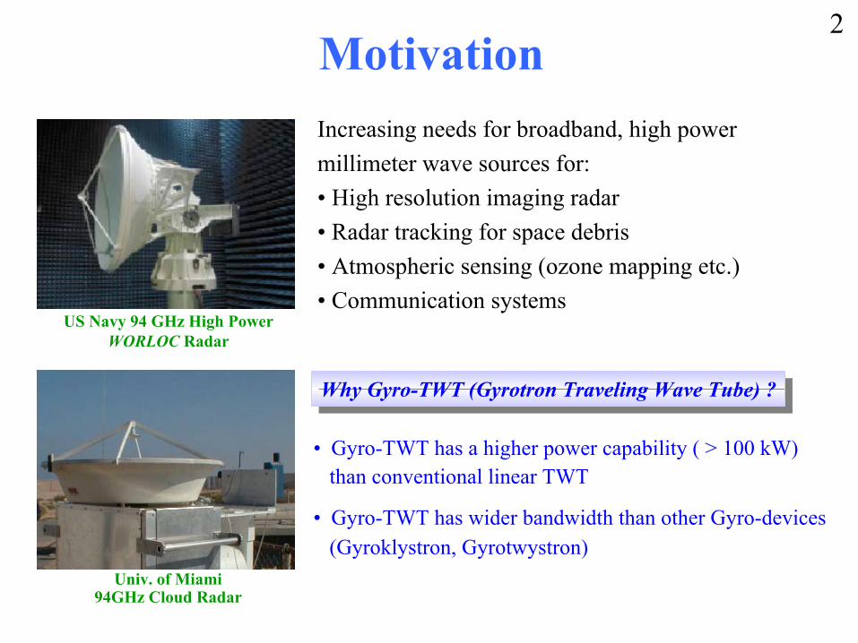
Motivation
US Navy 94 GHz High Power WORLOC Radar
Increasing needs for broadband, high power millimeter wave sources for:• High resolution imaging radar• Radar tracking for space debris• Atmospheric sensing (ozone mapping etc.)• Communication systems
• Gyro-TWT has a higher power capability ( > 100 kW)than conventional linear TWT
• Gyro-TWT has wider bandwidth than other Gyro-devices(Gyroklystron, Gyrotwystron)
Univ. of Miami 94GHz Cloud Radar
Why Gyro-TWT (Gyrotron Traveling Wave Tube) ?Why Gyro-TWT (Gyrotron Traveling Wave Tube) ?
2
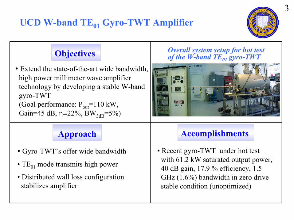
UCD W-band TE01 Gyro-TWT Amplifier
Overall system setup for hot test of the W-band TE01 gyro-TWT
• Extend the state-of-the-art wide bandwidth,high power millimeter wave amplifiertechnology by developing a stable W-bandgyro-TWT(Goal performance: Pout=110 kW,Gain=45 dB, η=22%, BW3dB=5%)
• Gyro-TWT’s offer wide bandwidth
• TE01 mode transmits high power
• Distributed wall loss configurationstabilizes amplifier
Objectives
Approach Accomplishments
• Recent gyro-TWT under hot testwith 61.2 kW saturated output power,40 dB gain, 17.9 % efficiency, 1.5GHz (1.6%) bandwidth in zero drivestable condition (unoptimized)
3
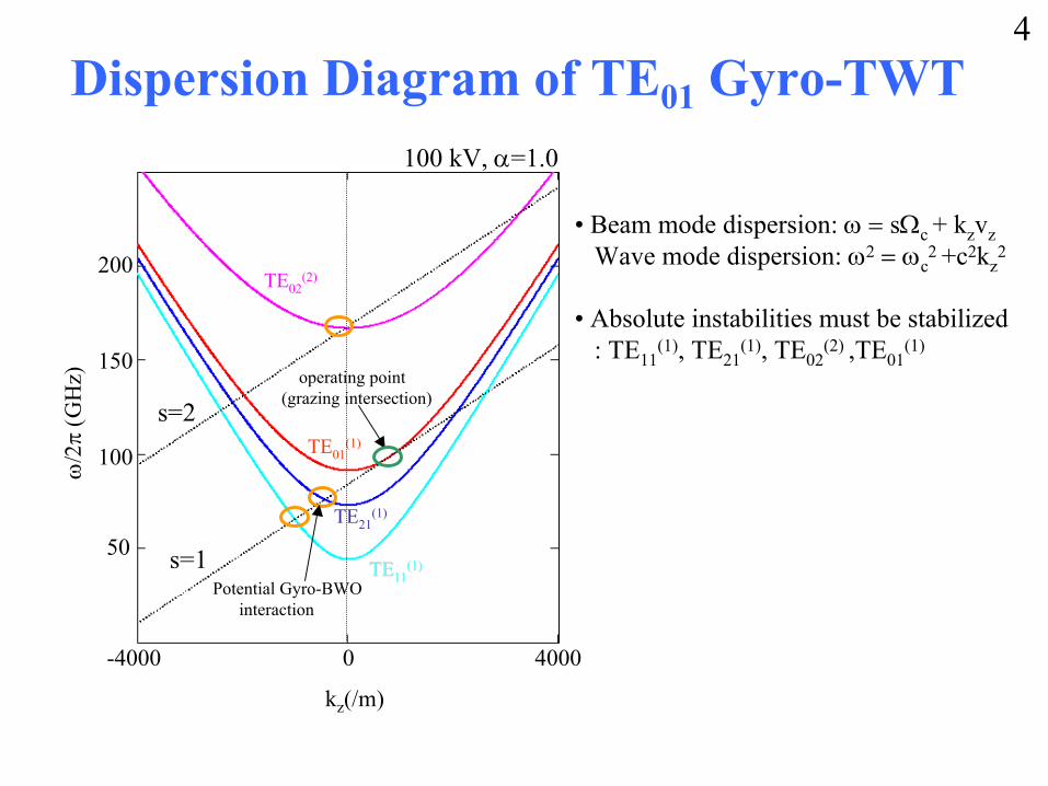
Dispersion Diagram of TE01 Gyro-TWT
• Beam mode dispersion: ω = sΩc + kzvzWave mode dispersion: ω2 = ωc
2 +c2kz2
• Absolute instabilities must be stabilized: TE11
(1), TE21(1), TE02
(2) ,TE01(1)
ω = sΩ c + k zv z
ω = sΩ c + k zv z
s = 1
s = 2
kz(/m)
50
100
150
200
0-4000 4000
ω/2
π (G
Hz)
TETE1111(1)(1)
TE21(1)
TE01(1)
TE02(2)
operating point(grazing intersection)
Potential Gyro-BWOinteraction
s=1
s=2
4
100 kV, α=1.0
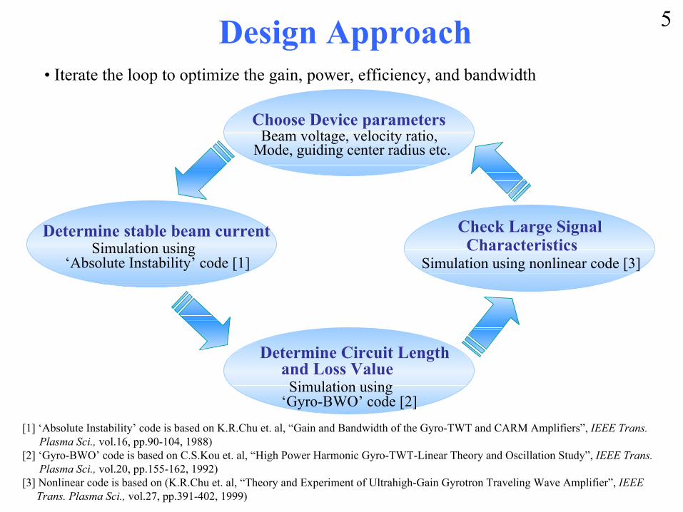
Design Approach
Beam voltage, velocity ratio,Mode, guiding center radius etc.
Choose Device parameters
Simulation using ‘Absolute Instability’ code [1]
Determine stable beam current
Simulation using ‘Gyro-BWO’ code [2]
Determine Circuit Lengthand Loss Value
Simulation using nonlinear code [3]
Check Large Signal Characteristics
• Iterate the loop to optimize the gain, power, efficiency, and bandwidth
[1] ‘Absolute Instability’ code is based on K.R.Chu et. al, “Gain and Bandwidth of the Gyro-TWT and CARM Amplifiers”, IEEE Trans.Plasma Sci., vol.16, pp.90-104, 1988)
[2] ‘Gyro-BWO’ code is based on C.S.Kou et. al, “High Power Harmonic Gyro-TWT-Linear Theory and Oscillation Study”, IEEE Trans.Plasma Sci., vol.20, pp.155-162, 1992)
[3] Nonlinear code is based on (K.R.Chu et. al, “Theory and Experiment of Ultrahigh-Gain Gyrotron Traveling Wave Amplifier”, IEEETrans. Plasma Sci., vol.27, pp.391-402, 1999)
5
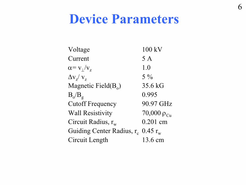
Device Parameters
Voltage 100 kV Current 5 Aα= v⊥/vz 1.0∆vz/ vz 5 %Magnetic Field(Bo) 35.6 kGBo/Bg 0.995Cutoff Frequency 90.97 GHzWall Resistivity 70,000 ρCuCircuit Radius, rw 0.201 cmGuiding Center Radius, rc 0.45 rw
Circuit Length 13.6 cm
6
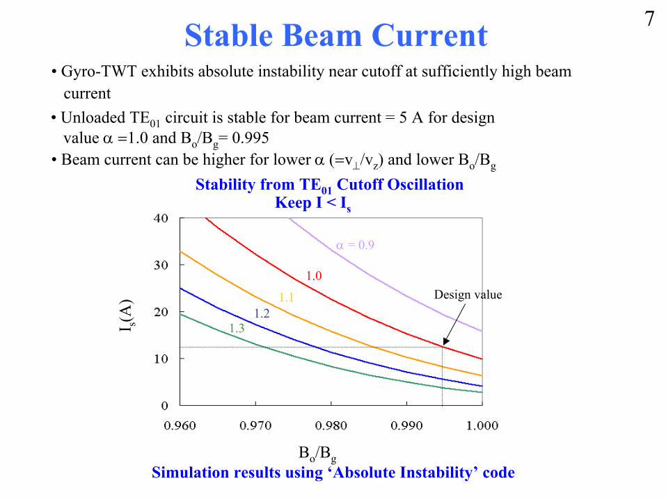
Stable Beam Current• Gyro-TWT exhibits absolute instability near cutoff at sufficiently high beam
current
• Beam current can be higher for lower α (=v⊥/vz) and lower Bo/Bg
• Unloaded TE01 circuit is stable for beam current = 5 A for designvalue α =1.0 and Bo/Bg= 0.995
α = 0.9
1.0
1.11.2
1.3
Bo/Bg
I s(A) Design value
Stability from TE01 Cutoff OscillationKeep I < Is
Simulation results using ‘Absolute Instability’ code
7
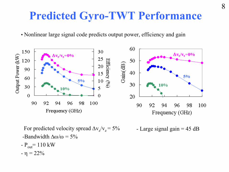
Predicted Gyro-TWT Performance
For predicted velocity spread ∆vz/vz = 5%-Bandwidth ∆ω/ω = 5%- Pout= 110 kW- η = 22%
- Large signal gain = 45 dB
• Nonlinear large signal code predicts output power, efficiency and gain
8
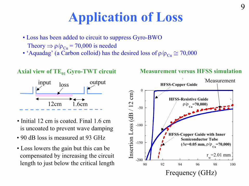
Application of Loss• Loss has been added to circuit to suppress Gyro-BWO
Theory ⇒ ρ/ρCu = 70,000 is needed• ‘Aquadag’ (a Carbon colloid) has the desired loss of ρ/ρCu ≅ 70,000
input outputloss
12cm 1.6cm
Axial view of TE01 Gyro-TWT circuit
• Initial 12 cm is coated. Final 1.6 cmis uncoated to prevent wave damping
Inse
rtion
Los
s (dB
/ 12
cm
)
Frequency (GHz)
-200
-150
-100
-50
0
90 92 94 96 98 100
HFSS-Copper Guide
HFSS-Copper Guide with InnerSemiconductor Tube (∆r=0.05 mm, ρ/ρ
Cu=70,000)
HFSS-Resistive Guide ρ/ρ
Cu=70,000)
rw
=2.01 mm
Measurement
Measurement versus HFSS simulation
• 90 dB loss is measured at 93 GHz
• Loss lowers the gain but this can becompensated by increasing the circuitlength to just below the critical length
9
Experimental Design and Setup
• Single Anode MIG
• High Voltage Modulator
• RF Couplers
• Interaction Circuit
• Vacuum System
• Superconducting Magnet System
• RF Drive Sources
• RF Diagnostics
10
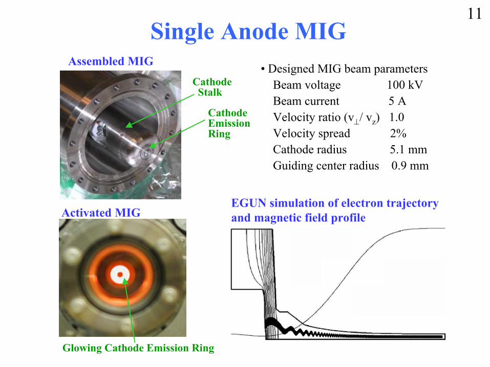
Single Anode MIG
Glowing Cathode Emission Ring
Activated MIG
Assembled MIG
Cathode Stalk
CathodeEmission Ring
• Designed MIG beam parametersBeam voltage 100 kV Beam current 5 AVelocity ratio (v⊥/ vz) 1.0Velocity spread 2% Cathode radius 5.1 mmGuiding center radius 0.9 mm
EGUN simulation of electron trajectoryand magnetic field profile
11
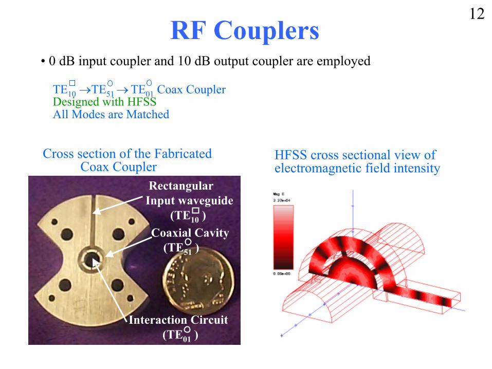
RF Couplers
Cross section of the Fabricated Coax Coupler
TE10 →TE51 → TE01 Coax CouplerDesigned with HFSSAll Modes are Matched
• 0 dB input coupler and 10 dB output coupler are employed
Rectangular Input waveguide
(TE10 )Coaxial Cavity
(TE51 )
Interaction Circuit(TE01 )
HFSS cross sectional view of electromagnetic field intensity
12
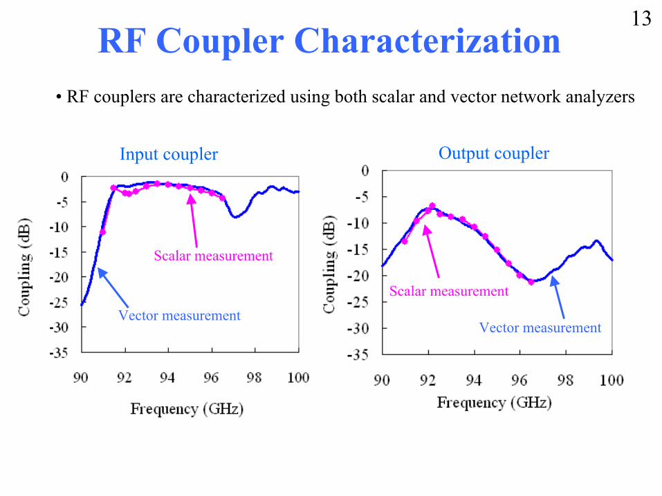
RF Coupler Characterization• RF couplers are characterized using both scalar and vector network analyzers
Input coupler
Scalar measurement
Vector measurement
Output coupler
Scalar measurement
Vector measurement
13
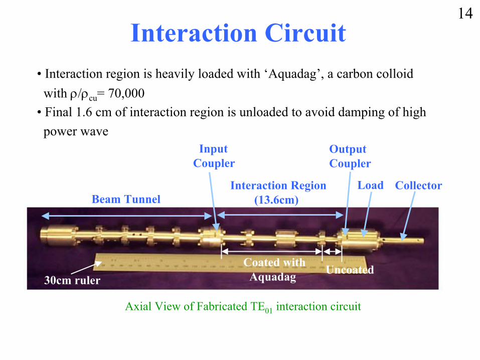
Interaction Circuit• Interaction region is heavily loaded with ‘Aquadag’, a carbon colloid
with ρ/ρcu= 70,000• Final 1.6 cm of interaction region is unloaded to avoid damping of high power wave
Axial View of Fabricated TE01 interaction circuit
Beam TunnelInteraction Region
(13.6cm)
Output Coupler
InputCoupler
Load Collector
Coated withAquadag Uncoated
30cm ruler
14
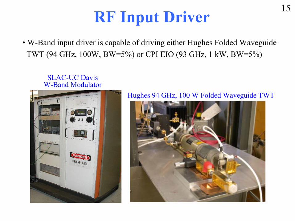
RF Input Driver• W-Band input driver is capable of driving either Hughes Folded Waveguide
TWT (94 GHz, 100W, BW=5%) or CPI EIO (93 GHz, 1 kW, BW=5%)
Hughes 94 GHz, 100 W Folded Waveguide TWT
SLAC-UC Davis W-Band Modulator
15
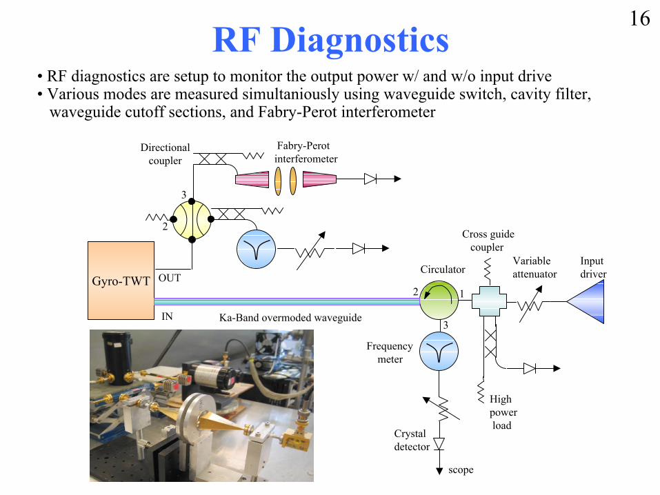
RF Diagnostics• RF diagnostics are setup to monitor the output power w/ and w/o input drive• Various modes are measured simultaniously using waveguide switch, cavity filter,
waveguide cutoff sections, and Fabry-Perot interferometer
Highpower load
CirculatorInputdriverGyro-TWT
IN
Frequencymeter
Directionalcoupler
1
3
2OUT
Variableattenuator
scope
Cross guide coupler
Crystaldetector
Ka-Band overmoded waveguide
3
2
Fabry-Perotinterferometer
16
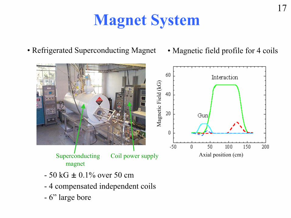
Magnet System
• Refrigerated Superconducting Magnet
Superconducting magnet
Coil power supply Axial position (cm)M
agne
tic F
ield
(kG
)
• Magnetic field profile for 4 coils
- 50 kG ± 0.1% over 50 cm - 4 compensated independent coils- 6” large bore
17
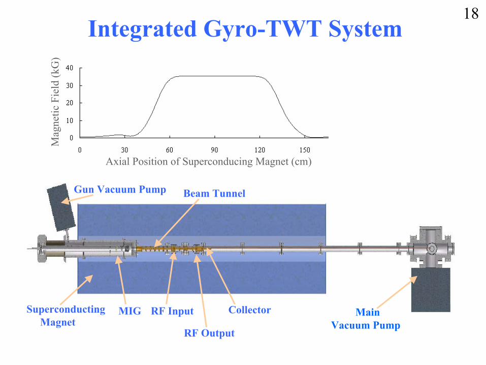
Integrated Gyro-TWT System
Superconducting Magnet
MIG MainVacuum Pump
RF Input
RF Output
Gun Vacuum Pump
Collector
Beam Tunnel
Axial Position of Superconducing Magnet (cm)
Mag
netic
Fie
ld (k
G)
18
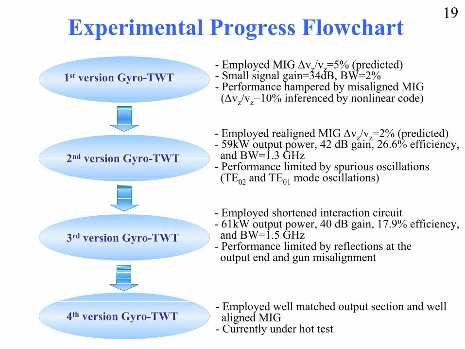
Experimental Progress Flowchart
1st version Gyro-TWT - Employed MIG ∆vz/vz=5% (predicted)- Small signal gain=34dB, BW=2%- Performance hampered by misaligned MIG(∆vz/vz=10% inferenced by nonlinear code)
2nd version Gyro-TWT
- Employed realigned MIG ∆vz/vz=2% (predicted) - 59kW output power, 42 dB gain, 26.6% efficiency, and BW=1.3 GHz
- Performance limited by spurious oscillations(TE02 and TE01 mode oscillations)
3rd version Gyro-TWT
4th version Gyro-TWT
- Employed shortened interaction circuit - 61kW output power, 40 dB gain, 17.9% efficiency,and BW=1.5 GHz
- Performance limited by reflections at the output end and gun misalignment
- Employed well matched output section and wellaligned MIG
- Currently under hot test
19
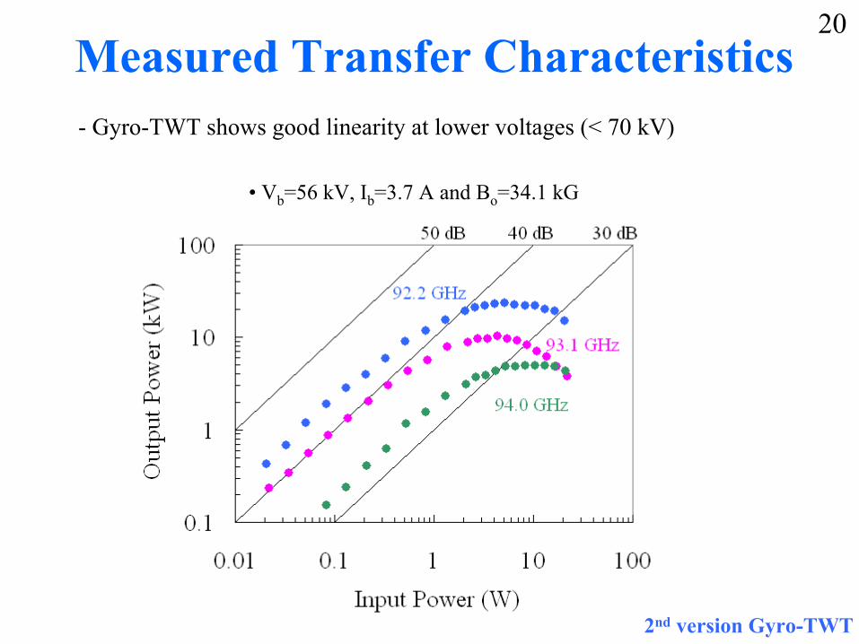
Measured Transfer Characteristics- Gyro-TWT shows good linearity at lower voltages (< 70 kV)
• Vb=56 kV, Ib=3.7 A and Bo=34.1 kG
2nd version Gyro-TWT
20
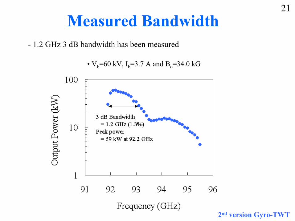
Measured Bandwidth- 1.2 GHz 3 dB bandwidth has been measured
• Vb=60 kV, Ib=3.7 A and Bo=34.0 kG
2nd version Gyro-TWT
21
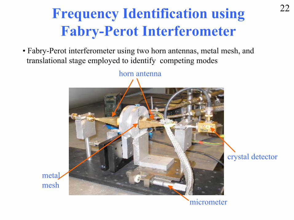
Frequency Identification using Fabry-Perot Interferometer
• Fabry-Perot interferometer using two horn antennas, metal mesh, andtranslational stage employed to identify competing modes
crystal detector
horn antenna
micrometer
metalmesh
22
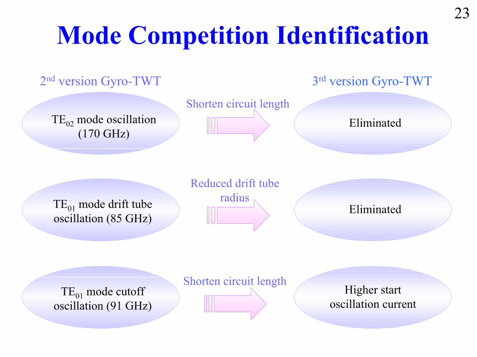
Mode Competition Identification23
2nd version Gyro-TWT 3rd version Gyro-TWT
TE02 mode oscillation (170 GHz)
EliminatedShorten circuit length
TE01 mode drift tube oscillation (85 GHz)
Eliminated
Reduced drift tube radius
TE01 mode cutoff oscillation (91 GHz)
Higher start oscillation current
Shorten circuit length
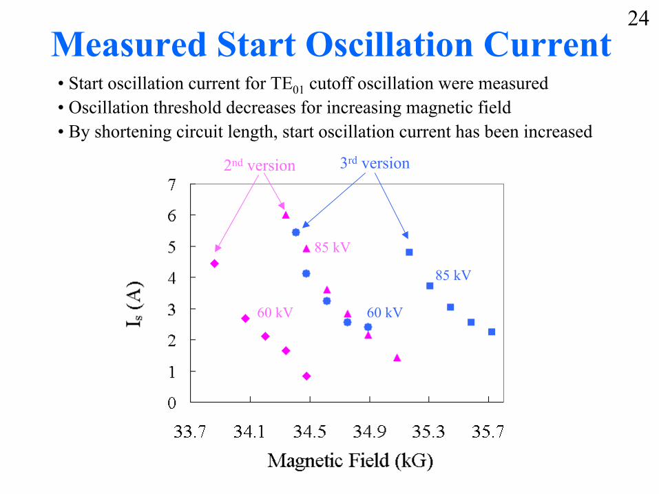
Measured Start Oscillation Current• Start oscillation current for TE01 cutoff oscillation were measured • Oscillation threshold decreases for increasing magnetic field• By shortening circuit length, start oscillation current has been increased
24
2nd version 3rd version
60 kV
85 kV
85 kV
60 kV
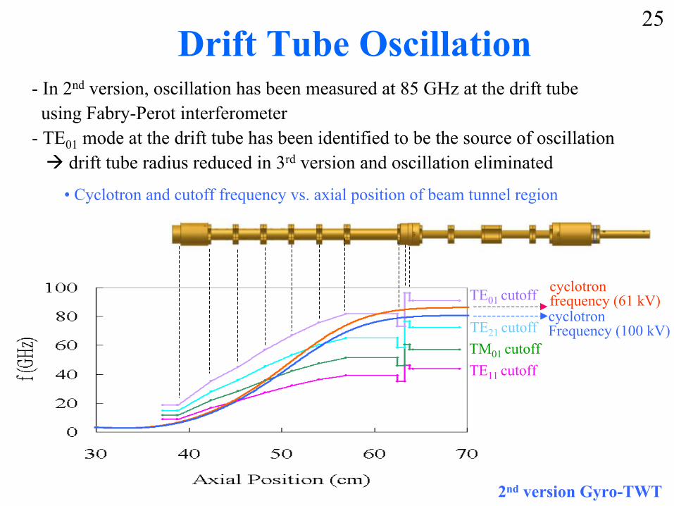
Drift Tube Oscillation- In 2nd version, oscillation has been measured at 85 GHz at the drift tubeusing Fabry-Perot interferometer
- TE01 mode at the drift tube has been identified to be the source of oscillationdrift tube radius reduced in 3rd version and oscillation eliminated
• Cyclotron and cutoff frequency vs. axial position of beam tunnel region
TE11 cutoffTM01 cutoffTE21 cutoff
TE01 cutoffcyclotronFrequency (100 kV)
cyclotronfrequency (61 kV)
2nd version Gyro-TWT
25
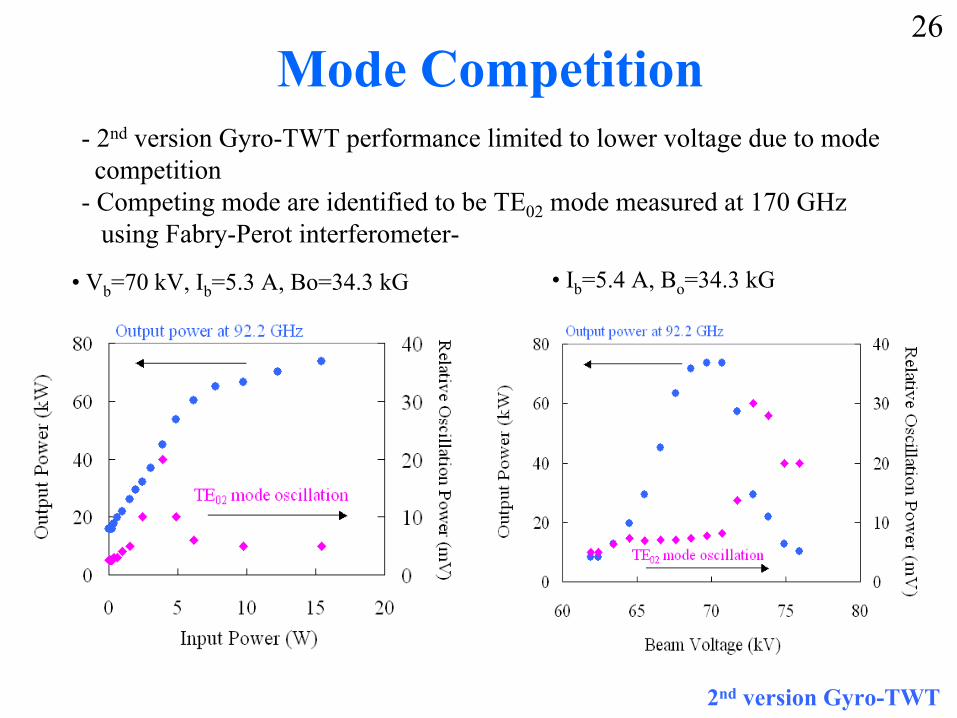
Mode Competition- 2nd version Gyro-TWT performance limited to lower voltage due to modecompetition
- Competing mode are identified to be TE02 mode measured at 170 GHz using Fabry-Perot interferometer-
• Vb=70 kV, Ib=5.3 A, Bo=34.3 kG • Ib=5.4 A, Bo=34.3 kG
2nd version Gyro-TWT
26
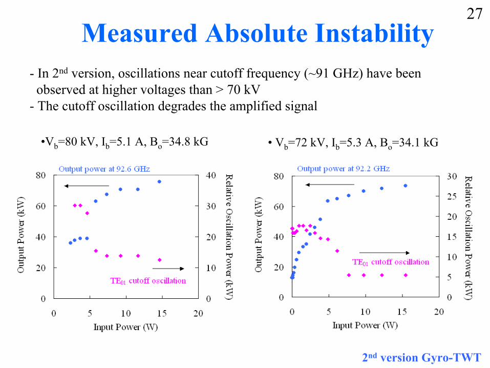
Measured Absolute Instability- In 2nd version, oscillations near cutoff frequency (~91 GHz) have beenobserved at higher voltages than > 70 kV
- The cutoff oscillation degrades the amplified signal
• Vb=72 kV, Ib=5.3 A, Bo=34.1 kG•Vb=80 kV, Ib=5.1 A, Bo=34.8 kG
2nd version Gyro-TWT
27
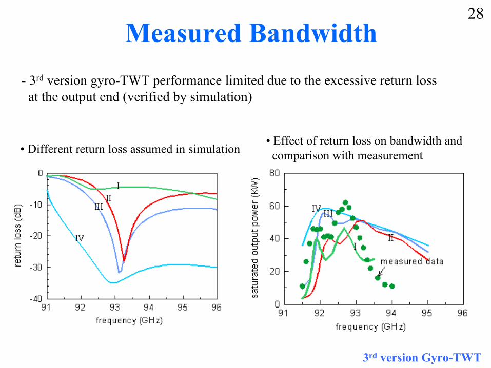
Measured Bandwidth- 3rd version gyro-TWT performance limited due to the excessive return loss at the output end (verified by simulation)
3rd version Gyro-TWT
28
• Different return loss assumed in simulation• Effect of return loss on bandwidth and comparison with measurement
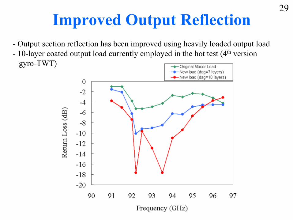
Improved Output Reflection- Output section reflection has been improved using heavily loaded output load- 10-layer coated output load currently employed in the hot test (4th version
gyro-TWT)
29
Summary• UCD 94 GHz TE01 Gyro-TWT has been constructed with predicted capability
of 110 kW with ∆ω/ω=5% and η=22%.• Circuit has been heavily loaded to suppress Gyro-BWO with 90 dB loss
measured at 93 GHz.
• 1st and 2nd version gyro-TWT performance limited by velocity spread and competing modes.
• Recent 3rd version gyro-TWT hot tested with 61.2 kW saturated output power, 40 dB gain, 17.9% efficiency, and 1.5 GHz bandwidth (1.6 % BW).
• To enhance the bandwidth and the output power, improved output section with reduced reflection and well aligned MIG are employed in the 4th version of gyro-TWT (currently under hot test).
30