Embed Size (px)
Citation preview

DEVELOPMENT OF BRIGHT AND DARK PULSED
FIBER LASER BASED ON NONLINEAR
POLARIZATION ROTATION
TIU ZIAN CHEAK
THESIS SUBMITTED IN FULFILLMENT OF THE
REQUIREMENT FOR THE DEGREE OF
DOCTOR OF PHILOSOPHY
DEPARTMENT OF ELECTRICAL ENGINEERING
FACULTY OF ENGINEERING
UNIVERSITY OF MALAYA
KUALA LUMPUR
2015

i
UNIVERSITI MALAYA
ORIGINAL LITERARY WORK DECLARATION
Name of Candidate: Tiu Zian Cheak (I.C/Passport No: 841008015853)
Registration/Matric No: KHA120120
Name of Degree: DOCTOR OF PHILOSOPHY
Title of Project Paper/Research Report/Dissertation/Thesis (“this Work”):
DEVELOPMENT OF BRIGHT AND DARK PULSED FIBER LASER BASED ON
NONLINEAR POLARIZATION ROTATION
Field of Study: Optical Communications
I do solemnly and sincerely declare that:
(1) I am the sole author/writer of this Work;
(2) This Work is original;
(3) Any use of any work in which copyright exists was done by way of fair dealing
and for permitted purposes and any excerpt or extract from, or reference to or
reproduction of any copyright work has been disclosed expressly and
sufficiently and the title of the Work and its authorship have been acknowledged
in this Work;
(4) I do not have any actual knowledge nor do I ought reasonably to know that the
making of this work constitutes an infringement of any copyright work;
(5) I hereby assign all and every rights in the copyright to this Work to the
University of Malaya (“UM”), who henceforth shall be owner of the copyright in
this Work and that any reproduction or use in any form or by any means
whatsoever is prohibited without the written consent of UM having been first
had and obtained;
(6) I am fully aware that if in the course of making this Work I have infringed any
copyright whether intentionally or otherwise, I may be subject to legal action or
any other action as may be determined by UM.
Candidate‟s Signature Date
Subscribed and solemnly declared before,
Witness‟s Signature Date
Name:
Designation:

ii
ABSTRACT
Pulsed lasers have many practical applications in both communication
and sensing. This thesis describes in detail the generation of bright pulses and dark
pulses lasers based on nonlinear polarization rotation (NPR). The passive techniques are
explored for pulse generation as they are reliable, compact, producing high beam quality
and do not require an external modulator. Various techniques such as film saturable
absorber (SAs), fiber SA and NPR techniques are studied to generate pulse.
Performance of graphene SA in Erbium-doped fiber laser (EDFL) with three different
gain mediums is successfully demonstrated. Q-switched EDFL are also demonstrated
using thulium-doped fiber as a SA. NPR technique is adopted in a ring EDFL to
generate Q-switched with low pump power. Besides the Q-switching operation, NPR
technique is also explored to generate mode-locked, harmonic mode-locked, and multi-
wavelength mode-locked. On the other hand, nonlinear Schrödinger equation (NLSE)
dark pulse, cubic-quintic nonlinear Schrödinger equation (CQNLSE) dark pulse and
domain wall (DW) dark pulse are demonstrated under different EDFL cavities based on
NPR technique. Furthermore, multi-wavelength dark pulse is achieved using PCF in
figure-of-eight cavity to slice the dark pulse spectrum. Besides, Q-switched dark pulse
is achieved in an unstable mode-locking operation, in which the Q-switching operation
modulated the dark pulses.

iii
ABSTRAK
Laser berdenyut mempunyai banyak aplikasi praktikal dalam kedua-dua
komunikasi dan penderiaan. Tesis ini menerangkan secara terperinci generasi laser
denyutan terang dan laser denyutan gelap berasas nonlinear polarization rotatation
(NPR). Teknik-teknik pasif yang diterokai untuk generasi nadi kerana mereka
dipercayai, padat, menghasilkan kualiti rasuk tinggi dan tidak memerlukan
peninggirendahan luar. Pelbagai teknik seperti filem saturable absorbers (SAs), serat SA
dan teknik NPR dikaji untuk menjana denyut. Prestasi graphene SA di Erbium-doped
fiber laser (EDFL) dengan tiga gain medium yang berbeza berjaya ditunjukkan. Q-
switched EDFL juga menunjukkan menggunakan gentian thulium-doped fiber sebagai
SA. Teknik NPR diguna pakai dalam EDFL untuk menjana Q-switched dengan kuasa
pam rendah. Selain operasi Q-switched, teknik NPR juga diteroka untuk menjana mode-
locked, harmonik mode-locked, dan laser pelbagai jarak gelombang mode-locked.
Sebaliknya, nonlinear Schrödinger equation (NLSE) nadi gelap, Cubic-quintic nonlinear
Schrödinger equation (CQNLSE) nadi gelap dan domain wall (DW) nadi gelap yang
ditunjukkan di bawah rongga EDFL berbeza berdasarkan teknik NPR. Tambahan pula,
pelbagai jarak gelombang nadi gelap dicapai menggunakan PCF dalam rajah-of-lapan
rongga untuk keping spektrum denyut gelap. Selain itu, Q-switched nadi gelap dicapai
dalam mode-locked operasi yang tidak stabil, di mana operasi Q-menukar termodulat
denyutan gelap.

iv
ACKNOWLEDGEMENT
First of all, I would like to express my appreciation to my supervisors, Prof. Dr.
Sulaiman Wadi Harun and Prof. Dr. Harith Ahmad for the continuous support,
motivation, patience and knowledge throughout my Ph.D study. Their guidance helped
me in all times of research and thesis writing.
My sincere gratitude also goes to Dr. Tan Sin Jin, Arman Zarei, Muneswaran
Suthaskumar and Dr. Afik for their help and knowledge sharing. You all brought so
much ideas to the lab despite the ups and downs that we encountered during our
research.
To my wife, parents and sibling, thank you for your encouragement and support.
Again, thank you to everyone who had helped me directly or indirectly with my
research.

v
TABLE OF CONTENTS
ABSTRACT ii
ABSTRAK iii
ACKNOWLEDGEMENT iv
TABLE OF CONTENTS v
LIST OF FIGURES viii
LIST OF SYMBOLS AND ABBREVIATIONS xiii
LIST OF PUBLICATION xv
CHAPTER 1 INTRODUCTION
1.1 Overview of Pulsed Laser 1
1.2 Thesis Objectives 4
1.3 Thesis Overview 4
1.4 Contribution 6
CHAPTER 2 LITERATURE REVIEW ON PULSE LASER
2.1 Introduction 8
2.2 Nonlinearity in Optical Fiber 9
2.2.1 Self-Phase Modulation 11
2.2.2 Cross-Phase Modulation 13
2.2.3 Four-wave Mixing 15
2.3 Pulsed Fiber Laser 16
2.3.1 Q-switching operation 16
2.3.2 Mode-locking operation 18
2.3.3 Dark pulse operation 20
2.4 The Nonlinear Schrodinger Equation 21
2.5 Saturable Absorber 22
2.5.1 Artificial Saturable Absorber with Nonlinear Polarization Rotation 22
2.5.2 Artificial Saturable Absorber with Nonlinear Optical Loop Mirror 26
vi
2.5.3 Film Saturable Absorber 28
CHAPTER 3 DEVELOPMENT OF PASSIVE Q-SWITCHED ERBIUM -DOPED
FIBER LASER
3.1 Introduction 30
3.2 Q-switched EDFL with graphene based SA 31
3.2.1 Fabrication and characterization of Graphene based SA 31
3.2.2 Experimental setup 33
3.2.3 Comparison of Q-switching performance at three different gain media 35
3.3 Q-switched EDFL using a solid state Thulium-doped Fiber SA 42
3.3.1 Configuration of the proposed Q-switched EDFL using a TDF SA 43
3.3.2 Q-switching performance 44
3.4 Q-switching pulse generation using nonlinear polarization rotation technique49
3.5 Multi-wavelength Q-switched Generation With Graphene Based SA 54
3.6 Summary 61
CHAPTER 4 DEVELOPMENT OF PASSIVE MODE-LOCKED ERBIUM-
DOPED FIBER LASERS
4.1 Introduction 63
4.2 NPR based mode-locked EDFL with three switchable operation states 64
4.2.1 Experimental setup 65
4.2.2 Comparison of the three different mode-locked operation states 66
4.3 Mode-locked square pulse emission with ultra-low repetition rate 71
4.3.1 Configuration of the proposed mode-locked square pulse EDFL 72
4.3.2 Mode-locked square pulse performance 73
4.4 Multi-wavelength mode-locked EDFL in figure-of-eight cavity 84
4.4.1 Configuration of the proposed multi-wavelength mode-locked EDFL 85
4.4.2 Multi-wavelength mode-locked performance 86
4.5 Summary 90

vii
CHAPTER 5 GENERATION OF DARK PULSES IN ERBIUM-DOPED FIBER
LASER CAVITY USING NONLINEAR POLARIZATION
ROTATION APPROACH
5.1 Introduction 92
5.2 Harmonic NLSE dark pulse emission in EDFL 93
5.2.1 Experimental setup 93
5.2.2 NLSE dark pulse performance 95
5.3 Generation of switchable DW and CQNLSE dark pulse 101
5.3.1 Configuration of the switchable DW and CQNLSE dark pulse EDFL 101
5.3.2 DW dark pulse performance 102
5.3.3 CQNLSE dark pulse performance 105
5.4 Multi-wavelength dark pulse EDFL in figure-of-eight cavity 107
5.4.1 Configuration of the proposed multi-wavelength dark pulse EDFL 108
5.4.2 Multi-wavelength dark pulse performance 109
5.5 Generation of Q-switched Mode-locked EDFL operating in dark regime 117
5.5.1 Experimental setup 118
5.5.2 Q-switched dark pulse performance 119
5.6 Summary 124
CHAPTER 6 CONCLUSION AND FUTURE OUTLOOK
6.1 Conclusion 125
6.2 Recommendations for Future Works 128
REFERENCES 130
APPENDIX 139

viii
LIST OF FIGURES
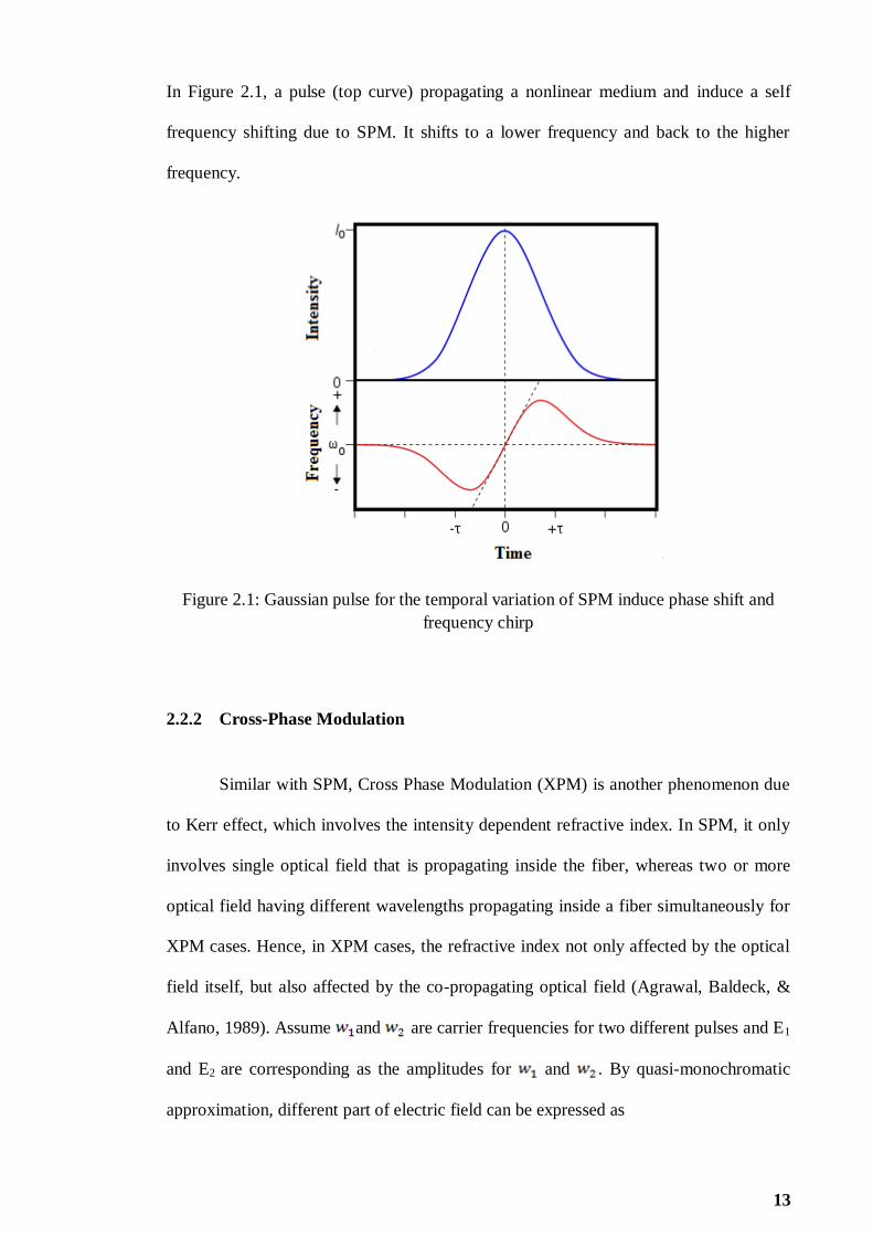
Figure 2.1: Gaussian pulse for the temporal variation of SPM induce phase shift and
frequency chirp 13
Figure 2.2: Schematic of FWM in frequency domain 15
Figure 2.3: Evolution of non-linear polarization rotation 23
Figure 2.4: Transmittivity of NPR 25
Figure 2.5: Basic configuration of NPR in ring cavity 26
Figure 2.6: Working principle of APM (a) a typical APM coupled cavity laser (b) The
pulse of main cavity adds to the pulse of the auxiliary cavity to result in a shortened
pulse at the output of beam splitter 27
Figure 2.7: Basic configuration of NOLM 28
Figure 2.8: Basic configuration of film saturable absorber 29
Figure 3.1: Raman spectrum of the fabricated SA 33
Figure 3.2: Schematic configuration of the Q-switched EDFL 35
Figure 3.3: Optical spectrum of the Q-switched EDFLs when the pump is fixed at
threshold power 36
Figure 3.4: Pulse repetition rate against pump power for the EDFL configured with
three different EDFs 37
Figure 3.5: Pulse width versus pump power for the EDFL configured with three
different EDFs 38
Figure 3.6: Pulse train of maximum pulse repetition rate at three different gain medium
(a) Silica EDF (400 ppm) (b) Silica EDF (2000 ppm) and (c) Bismuth EDF (3000 ppm)
40
Figure 3.7: Output power against pump power for three different gain medium 41
Figure 3.8: Pulse energy against pump power for three different gain medium 41
Figure 3.9: Schematic configuration of the proposed thulium fiber based Q-switched
EDFL 44
Figure 3.10: Q-switched pulse evoluation of the proposed Q-switched EDFL against
pump power 45

ix
Figure 3.11: Optical spectrum and of the proposed Q-switched EDFL when the pump is
fixed at 33.7 mW 46
Figure 3.12: Repetition rate and pulse width of the proposed Q-switched EDFL against
the pump power 48
Figure 3.13: Output power and pulse energy of the proposed Q-switched EDFL against
the pump power 48
Figure 3.14: Schematic configuration of the proposed Q-switched EDFL 50
Figure 3.15: Pulse evolution of the proposed Q-switched EDFL against pump power 51
Figure 3.16: Optical spectrum for the Q-switched EDFL at threshold pump power 51
Figure 3.17: Output power and pulse energy of the proposed Q-switched EDFL against
pump power 53
Figure 3.18: Repetition rate and pulse width of the proposed Q-switched EDFL against
pump power 53
Figure 3.19: Schematic configuration of the proposed multi-wavelength Q-switched
EDFL 55
Figure 3.20: (a) Optical spectrum and (b) typical pulse train of the proposed multi-
wavelength Q-switched EDFL when the pump is fixed at the threshold pump power of
39.6 mW 56
Figure 3.21: Output spectrum evolution of the proposed multi-wavelength Q-switched
EDFL against pump power 58
Figure 3.22: Repetition rate and pulse width of the proposed multi-wavelength Q-
switched EDFL against pump power 60
Figure 3.23: Output power and pulse energy of the proposed multi-wavelength Q-
switched EDFL against pump power 60
Figure 3.24: Output spectrum evolution of the proposed multi-wavelength Q-switched
EDFL against time 61
Figure 4.1: Schematic configuration of the mode-locked EDFL 66
Figure 4.2: Typical pulse train of the proposed mode-locked EDFL at two different
pump powers of 17.5 mW and 34.3 mW. Inset shows the corresponding cingle pulse
envelops 67
Figure 4.3: Typical pulse trains of the mode-locked EDFL at pump powers of 48.2 mW
and 116.7 mW, which operate at fundamental mode 69
Figure 4.4: Pulse train obtained from proposed EDFL with pump power of 138.9 mW
and 145 mW 69

x
Figure 4.5: Optical spectrum of the mode-locked laser at various pump powers 71
Figure 4.6: Experimental set-up of the proposed DSR laser 73
Figure 4.7: Optical output spectra of pulse laser at three different pump powers 75
Figure 4.8: Typical pulse train with a fundamental repetition rate at 10.2 kHz 75
Figure 4.9: Oscilloscope trace of the single square pulse envelop at two different pump
powers 76
Figure 4.10: Pulse width of the square pulse versus pump power 77
Figure 4.11: RF spectrum of the generated pulses: (a) square pulse and (b) harmonic
pulse 78
Figure 4.12: Typical pulse train of the mode-locking pulse at two different pump
powers: (a) 100 mW and (b) 108 mW 80
Figure 4.13: Output spectrum of the harmonic mode-locked EDFL 81
Figure 4.14: Measured output power for square and harmonic pulse at various pump
powers 82
Figure 4.15: Pulse energy of produced pulse for square and harmonic pulse 83
Figure 4.16: Schematic configuration of the proposed multi-wavelength mode-locked
EDFL 86
Figure 4.17: Output of the proposed multi-wavelength mode-locked EDFL at pump
power of 146 mW: (a) Optical spectrum and (b) typical mode-locked pulse train 88
Figure 4.18: RF spectrum of the proposed multi-wavelength mode-locked EDFL 90
Figure 5.1: Schematic configuration of the proposed dark pulse EDFL 95
Figure 5.2: Dark pulse emission of the proposed EDFL at different orders of harmonic:
(a) fundamental, (b) 2nd
, (c) 3rd
, (d) 4th, and (e) 5
th 97
Figure 5.3: Threshold pump power and output power at different order harmonic 99
Figure 5.4: Pulse width and pulse energy against different order harmonic 100
Figure 5.5: Output spectra of the dark pulse train at different order harmonics 100
Figure 5.6: Experimental set-up of the proposed mode-locked EDFL, which capable for
generating a switchable DW and NLSE dark pulse train 102
Figure 5.7: Typical DW dark pulse train at pump power of 140 mW 103
Figure 5.8: DW dark pulse spectrum of the proposed EDFL at pump power of 140 mW
104

xi
Figure 5.9: DW dark pulse RF spectrum of the proposed EDFL at pump power of 140
mW 105
Figure 5.10: CQNLSE dark pulse train of the proposed EDFL at pump power of 140
mW 106
Figure 5.11: Output optical spectrum of the CQNLSE dark pulse at pump power of 140
mW 107
Figure 5.12: RF spectrum of the CQNLSE dark soliton pulse at pump power of 140 mW
107
Figure 5.13: Schematic configuration of the proposed multi-wavelength mode-locked
EDFL 109
Figure 5.14: Multi-wavelength output spectrum evolution against 1480 nm pump power
110
Figure 5.15: Optical spectrum of the proposed multi-wavelength dark pulse EDFL at
four different orientation of PC when the pump is fixed at 146 mW (a) fundamental (b)
2nd
order (c) 3rd
order and (d) 4th
order harmonic operation 113
Figure 5.16: Dark pulse train of the proposed multi-wavelength dark pulse EDFL at four
different orientation of PC when the pump is fixed at 146 mW (a) fundamental (b) 2nd
order (c) 3rd
order and (d) 4th order harmonic operation 115
Figure 5.17: Pulse width and pulse energy at different orders of harmonic. Inset shows
single dark pulse at 4th order harmonic 117
Figure 5.18: Schematic configuration of the proposed QML EDFL emitting dark pulse
118
Figure 5.19: Emission of Q-switched dark pulse train againsts pump power 119
Figure 5.20: Emission of single Q-switched dark pulse at pump power of 145 mW 120
Figure 5.21: Output spectrum at pump power of 145 mW 120
Figure 5.22: Pulse repetition rate and pulse width of the proposed Q-switched dark pulse
EDFL 121
Figure 5.23: Output power and pulse energy of the proposed Q-switched dark pulse
EDFL 122
Figure 5.24: Dark square pulse at different pump power, Inset shows single Q-switched
dark pulse which consists of first dip and trailing dark pulses 123

xii
LIST OF TABLES
Table 3.1: Summary of laser performance for three different gain media 42

xiii
LIST OF SYMBOLS AND ABBREVIATIONS
Aeff Effective area
Leff Effective length
Β2 Group velocity dispersion parameter
I Light intensity
α Nonlinear coefficient
n2 Nonlinear refractive index
Pth Threshold power
T Transmittivity of light
λ Wavelength
AC Auto-correlator
ASE Amplified Spontaneous Emission
Bi-EDF Bismuth-Erbium Doped Fiber
CW Continuous Wave
DCF Dispersion Compensation Fiber
DSF Dispersion Shifted Fiber
DWDM Dense Wavelength Division Multiplexing
EDF Erbium Doped Fiber
EDFL Erbium Doped Fiber Laser
EDFA Erbium Doped Fiber Amplifier

xiv
FWHM Full Width Half Maximum
FWM Four-Wave Mixing
GVD Group Velocity Dispersion
HNLF Highly Nonlinear Fiber
NRP Nonlinear Polarization Rotation
NALM Nonlinear Amplifying Loop Mirror
NOLM Nonlinear Optical Loop Mirror
OSA Optical Spectrum Analyzer
OSC Oscilloscope
OSNR Optical Signal to Noise Ratio
OTDM Optical Time Division Multiplexing
PC Polarization Controller
PCF Photonic Crystal Fiber
RFSA Radio Frequency Spectrum Analyzer
SA Saturable Absorber
SMF Single Mode Fiber
SNR Signal to Noise Ratio
SOA Semiconductor Optical Amplifier
SPM Self-Phase Modulation
TDM Time Division Multiplexing
WDM Wavelength Division Multiplexing
XPM Cross Phase Modulation
xv
LIST OF PUBLICATION
Journal Publications
Tiu, Z. C., Ahmad, F., Tan, S. J., Ahmad, H., & Harun, S. W. (2014). Passive Q-
switched Erbium-doped fiber laser with graphene–polyethylene oxide saturable
absorber in three different gain media. Indian Journal of Physics, 88(7), 727-
731.
Tiu, Z. C., Tan, S. J., Zarei, A., Ahmad, H., & Harun, S. W. (2014). Nonlinear
Polarization Rotation-Based Mode-Locked Erbium-Doped Fiber Laser with
Three Switchable Operation States. Chinese Physics Letters, 31(9), 094206.
Tiu, Z. C., Ahmad, F., Tan, S. J., Zarei, A., Ahmad, H., & Harun, S. W. (2014). Multi-
wavelength Q-switched Erbium-doped fiber laser with photonic crystal fiber and
multi-walled carbon nanotubes. Journal of Modern Optics, 61(14), 1133-1139.
Tan, S. J., Tiu, Z. C., Harun, S. W., & Ahmad, H. (2014). Square pulse emission with
ultra-low repetition rate utilising non-linear polarisation rotation technique. The
Journal of Engineering, 1(1).
Tiu, Z. C., Tan, S. J., Ahmad, H., & Harun, S. W. (2014). Dark pulse emission in
nonlinear polarization rotation-based multiwavelength mode-locked erbium-
doped fiber laser. Chinese Optics Letters, 12(11), 113202.
Tiu, Z. C., Zarei, A., Tan, S. J., Ahmad, H., & Harun, S. W. (2014). Q-Switching Pulse
Generation with Thulium-Doped Fiber Saturable Absorber. Chinese Physics
Letters, 31(12), 124203.
Zarei, A., Tiu, Z. C., Ahmad, F., Ahmad, H., & Harun, S. W. (2015). Q-switched
Brillouin fibre laser with multi-wall carbon nanotube saturable absorber. IET
Optoelectronics, 9(2), 96-100.
Zian, C. T., Arman, Z., Sin, J. T., Harith, A., & Sulaiman, W. H. (2015). Harmonic
Dark Pulse Emission in Erbium-Doped Fiber Laser. Chinese Physics Letters,
32(3), 034203.
Tiu, Z. C., Ahmad, F., Tan, S. J., Ahmad, H., & Harun, S. W. (2014). Multi-wavelength
Q-switched Erbium-doped fiber laser with photonic crystal fiber and graphene-
polyethylene oxide saturable absorber. Optik, DOI: 10.1016/j.ijleo.2015.04.036.

1
CHAPTER 1
INTRODUCTION
1.1 Overview of Pulsed Laser
Pulsed lasers have been of great interest as they have many applications in
telecommunication, remote sensing, signal processing and medicine. Various laser
setups are widely studied to generate pulses with different and distinctive pulse
characteristics. Therefore, each of the laser setup can be customized to suit for different
applications. For instance, pulsed laser designed with high peak intensity and high pulse
energy is widely used for micromachining, cutting and drilling which benefits the
electronic and automotive industries (Nikumb et al., 2005). In the medical field, pulsed
laser is used in surgeries (Plamann et al., 2010; Serbin et al., 2002). One of the
applications of pulsed laser is in eye surgery, where the system is known as the laser-
assisted in situ keratomileusis (LASIK) (Kezirian & Stonecipher, 2004; Montés-Micó,
Rodríguez-Galietero & Alió, 2007). In LASIK surgery, ultra-voilet (UV) laser source is
used to photo-ablate the corneal tissue rather than mechanical cutting which will
somehow damage the surface layer or cornea and the surrounding cells. On the other
hand, pulsed laser is used to mark information such as batch number, manufactured date
and logo (Noor et al., 1994) in the electronic semiconductor manufacturing industry.
Furthermore, in telecommunication field, ultra-short optical pulses have been widely
used in optical transmission technology for achieving a high speed and long distance
network (Salehi, Weiner, & Heritage, 1990; Mendez et al., 2000). With the
exponentially growth of information technology in past decade, billions of computers
are linked and information such as voice, data, image, and video are exchanged. For
2
instance, services such as voice over Internet Protocol (VoIP) are able to allow users to
communicate in very low cost compare to traditional public switched telephone network
(PSTN). Nonetheless, the demands of higher data rate transmission are still in a
tremendously growth as the number and needs of users are increasing. To achieve a
high capacity transmission, multiplexing with Wavelength Division Multiplexing
(WDM) and Optical Time Division Multiplexing (OTDM) are effective solutions in
current technology.
WDM is a technology by which multiple optical channels can be combined
together and simultaneously transmitted at different wavelengths through a single
optical fiber. The broad bandwidth supercontinuum (SC) light source generated by a
pulsed laser can be sliced into many wavelength channels to serve as a source in WDM
system (Morioka et al., 1994). The SC light source can be produced by leading the
pulsed laser output into a nonlinear fiber such as photonic crystal fiber (PCF), highly
nonlinear fiber (HNLF) and dispersion compensated fiber (DCF) (Hossain, Namihira &
Razzak, 2012; Mori et al., 1997). Spectrum broadening is formed as a result of
nonlinear interaction such as self-phase modulation (SPM), cross-phase modulation
(XPM) and four wave mixing (FWM) in the nonlinear fiber. SC source extending from
1200 nm up to region above 1750 nm has been obtained from an amplified mode-locked
pulse of 800 fs in conjunction with 100 m PCF (Shahabuddin et al., 2012). In Dense
Wavelength Division Multiplexing (DWDM) system, the broad light spectrum can be
sliced into hundreds or even thousands of wavelengths and each of the wavelengths can
function as individual channel carrier.
In OTDM technology, high bit rate data stream is achieved by multiplexing a
number of low bit rate optical channels in the time domain. Several types of pulsed laser
sources are widely utilized in OTDM system, which are included mode-locked fiber
laser in ring cavity, semiconductor mode-locked laser and distributed feedback laser

3
(DFB) with modulator. OTDM system shows a promising potential for next generation
of telecommunication technology. For instance, ultra-high speed at 1.28 Tb/s in OTDM
transmission over 70 km had been demonstrated using ultra-short femto-second soliton
with 10 GHz per channel at the transmitter (Mulvad et al., 2010; Nakazawa, 2000).
Furthermore, soliton pulses are desirable transmitting sources for ultra-long haul
transmission and it was successfully implemented and demonstrated in a propagation
distance up to one million km (Nakazawa et al., 1991). Among the different types of
pulses, dark pulse can provide better signals for telecommunications. The dark pulses,
which consist of intensity dips under a continuous beam of laser light, are effectively
the opposite of the bright bursts in a normal pulsed laser. Dark pulse train can be
generated with 90 ps pulse width, and just 30% of the normal intensity is needed
compared to conventional bright pulse (Feng et al., 2010).
There are various techniques that can be utilized to generate different types of
pulsed laser to fit into different applications. Generally, these methods can be classified
into two techniques, which are active and passive pulsing techniques. In active
techniques, an external modulator is needed to electronically synchronize to the cavity
repetition rate. In passive technique, the external synchronization is not required, but
rather adopts an all optical nonlinear process in a laser resonator. The structures of
active mode-locked lasers are considered complex, complicated and bulky with the
employment of external modulator, whereas for passive method, the mechanism used is
by generating saturable absorption action. Saturable absorption can be achieved by real
saturable absorbers (SAs) or can also exploit the artificial SAs. Real SAs such as
semiconductors and the newly discovered carbon nanotubes (CNTs) and graphene,
whereas the most prominent artificial SA is called nonlinear polarization rotation
(NPR), which is also known as additive pulse mode-locking (APM) (Haus, Ippen &
Tamura, 1994). The advantages of passive over active mode-locking are for its simple
4
and compact construction, cost efficiency, robustness and ultra-short pulse generation
(Sotor et al., 2012). This PhD work is intended to explore several passive pulsing
approaches as well as the formation of different pulse profiles.
1.2 Thesis Objectives
Pulsed lasers are important and widely used in communication and electronics
industries. This work aim to implement and demonstrate practical pulsed laser based on
nonlinear effects in optical fibers. To achieve this, several objectives have been outlined
to guide the research direction toward the goal:
1. To study various passive techniques to generate pulsed laser.
2. To demonstrate Q-switched fiber laser using real saturable absorber and artificial
saturable absorber.
3. To generate mode-locked fiber laser using NPR technique.
4. To generate dark pulse using NPR technique.
1.3 Thesis Overview
This thesis is organized into six chapters which comprehensively demonstrate
the generation of pulsed laser based on nonlinear effects. Chapter 1 gives a brief
description on the recent developments and applications of pulsed lasers. Besides, the
motivations and objectives of this study are also highlighted. Moreover, an overview
and the contributions of this thesis to the pool of knowledge are also summarized.
Chapter 2 provides a detailed theoretical background and fundamental principles on the
relevant nonlinear effects in the optical fiber that are responsible for the generation of

5
pulsed lasers. Various pulsing operation and pulsing techniques are also reviewed in this
chapter.
Chapter 3 demonstrates Q-switched fiber lasers based on real saturable absorber
and artificial saturable absorber. Real saturable absorbers are included graphene film
saturable absorber and fiber saturable absorber, whereas the artificial saturable absorber
is based on NPR techniques. The performances of these lasers are compared in terms of
threshold pump power, pulse stability, pulse energy and pulse repetition rate and ease of
implementation. Besides, multi-wavelength Q-switched fiber laser can also be
implemented via graphene saturable absorber combined with NPR technique. This
chapter concludes that NPR technique is the simplest and most practical. Therefore,
NPR technique is chosen for further exploration in realizing mode-locked fiber laser in
the following chapters.
Chapter 4 focuses on the generation of mode-locked fiber laser using NPR
technique. In this chapter, various NPR based fiber lasers are demonstrated using
dispersion compensation fiber (DCF), single mode fiber (SMF) and photonic crystal
fiber (PCF) as the nonlinear medium. A new three switchable operation state mode-
locked fiber laser is demonstrated by using DCF. Besides, square pulse mode-locking
operation is achieved based on a spool of long SMF. Finally, a multi wavelength mode-
locked fiber laser with figure-of-eight cavity is proposed using PCF to slice the mode-
locked spectrum.
Chapter 5 focuses on generating dark pulses based on NPR techniques. Three
different types of dark pulses are demonstrated, which are included nonlinear
Schrödinger equation (NLSE) dark pulse, cubic-quintic nonlinear Schrödinger equation
(CQNLSE) dark pulse and domain wall (DW) dark pulse. Furthermore, multi-
wavelength dark pulse is achieved using PCF in figure-of-eight cavity to slice the dark
pulse spectrum. Besides, Q-switched dark pulse is achieved in an unstable mode-

6
locking operation, in which the Q-switching operation modulated the dark pulses.
Finally, chapter 6 summarizes the findings for this PhD work.
1.4 Contributions
The major contributions of this research work are summarized below:
1. Demonstration Q-switched Erbium-doped fiber laser (EDFL) incorporated graphene
saturable absorber in three different gain media. The performance of three different
gain media is compared in term of pulse energy, pulse width, pulse repetition rate
and threshold pump power.
2. Development of fiber saturable absorber based Q-switched fiber laser. Thulium-
doped fiber laser is used to achieve saturable absorption in a EDFL which operated
at 1570 nm wavelength.
3. Demonstration of multi-wavelength Q-switched EDFL in figure-of-eight cavity.
Graphene saturable absorber is used to generate Q-switched in main loop, whereas
PCF is incorporated in second loop to slice the Q-switched spectrum into multi-
wavelength operation.
4. Demonstration various mode-locked operation. Mode-locked in three switchable
operation, mode-locked square pulse operation and multi-wavelength mode-locked
operation are implemented in different types of birefringent nonlinear medium.
5. Development of dark pulse EDFL based on several techniques, which are included
NLSE dark pulse, CQNLSE dark pulse and DW dark pulse: NLSE dark pulse
generation is based on Kerr nonlinearities, whereas CQNLSE dark pulse generation
is based on non-Kerr nonlinearities. Besides, DW dark pulse generation is relied on
dual wavelength oscillation.

7
6. Demonstration of multi-wavelength dark pulse: Dark pulse spectrum is sliced into
multi-wavelength operation by using PCF to generate NPR effect in figure-of-eight
cavity.
7. Demonstration of Q-switched mode-locking operation in dark regime: Q-switched
and dark pulse co-existed in the laser cavity. Q-switched operation modulates the
dark pulse to achieve Q-switched mode-locking operation in dark regime.

8
CHAPTER 2
LITERATURE REVIEW ON PULSE LASER
2.1 Introduction
The generation of laser in 1960s has intensively enhanced the developments for
both telecommunication (Aubin et al., 1995) and sensor technology (Giallorenzi et al.,
1982). The invention of low loss silica based optical fibers further initiated a revolution
in optical fiber communication, and induced the discovery of fiber material and the
associated nonlinear optical effects. Nonlinear optical effects are one of the interesting
phenomena in optical fiber transmission system. In recent years, many researches had
been carried out to study nonlinear optical effects such as Self Phase Modulation (SPM)
(Agrawal & Olsson, 1989), Cross Phase Modulation (XPM) (Agrawal, 1987), and Four
Wave Mixing (FWM) (Deng et al.,1999). The broad studies of nonlinear effects has
further triggered the advancement of knowledge in pulsed fiber laser. Unlike the
conventional laser which operates in continuous wave (CW), pulsed lasers can generate
optical pulses based on either Q-switching or mode-locking principles. Basically, pulsed
laser can operate in two different regimes, which are bright regime and dark regime
(Sylvestre, 2002). Dark pulses are normally referred to a train of intensity dips in a cw
background of the laser emission. However, most of the pulsed lasers operate in bright
regime.
Up to date, many techniques have been proposed and demonstrated to generate
pulsed fiber laser based on both active and passive techniques (Keller, 2003). Passive
techniques use saturable absorber such as graphene (Bao et al., 2009; Luo et al., 2010),
carbon nanotubes (Set, et al., 2004; Im et al., 2010), solid-state fiber, semiconductor
saturable absorber mirror (SESAM) (Sutter et al., 1999; Chen et al., 2011) as well as

9
artificial saturable absorber based on nonlinear polarization rotation (NPR) (Kim, Kutz,
& Muraki, 2000; Liu et al., 2008). Among these passive techniques, NPR has attracted
the attention from scientists due to low cost and ease of implementation in generation of
pulsed laser. The NPR effect occurs in nonlinear fiber due to Kerr effect where different
intensity of light will rotate at different angle. This allows NPR effect to work as an
artificial saturable absorber to generate pulsed laser.
The main objective of this research aims to study on various pulsed fiber laser
generation based on NPR technique. In this chapter, literature reviews on nonlinear
effects, Q-switching and mode-locking principles, saturable absorbers and dark pulses
are presented.
2.2 Nonlinearity in Optical Fiber
Lasers nonlinear response is a phenomenon which does not obey the
superposition principle (Lehmann & Romanini, 1996), or whose output is not directly
proportional to its input. To visualize the basic idea of nonlinear response, we may
derive it in mathematics form. Consider in a system, response is given by
(2.1)
where x is the input signal and a1 is the linear gain of the system. An applied field is
given by
(2.2)
Output is given by
(2.3)
The output is a faithful representation of input within the linear region. When the
applied field increases and goes beyond the system‟s linear region, the output become
distorted due to the nonlinear response and can be written as

10
(2.4)
The cubic distortion has been chosen for the assumption since in most of the
nonlinear optic works, the focus has normally be given to the third order nonlinear
effect. By substituting equations (2.2) and (2.3) into (2.4), the output become
(2.5)
Trigonometric identity given as
(2.6)
From above equation, it is found that the cubic distortion increases a modified response
in frequency , and also creates a new signal at frequency 3 .
In optical fibers, the nonlinear response may occur due to an intense applied
field. In other word, the nonlinear response in optical fibers relies upon the harmonic
motion of bound electron affected by the applied field. In linear region, the response of
total polarization, P due the electric field, E can be described as
(2.7)
where is permittivity of free space and is linear susceptibility, and it can be
shown that
(2.8)
where n is the refractive index of the medium. This describes the linear propagation
give rise to i) Real part, speed of propagation through the medium, and ii) Imaginary
part, absorption in the medium. By expanding the polarization in power series in E, it
gives
(2.9)
where , and etc are second and third order nonlinear susceptibilities,
respectively. The second order susceptibility is related to the nonlinear effect such
as second harmonic generation and sum-frequency generation. In most of the situation,

11
optical fiber will not exhibit the second order nonlinear effect due to the immersion
symmetry molecule characteristic. Obviously, the lowest order nonlinear effect in fiber
is caused by third order susceptibility . Kerr effect is a change of the refractive
index changed due to the applied electric field. For Kerr effect in fiber optic, the third
order susceptibility is significant. In Sellmeier equation
(2.10)
where is the th resonance and is the resonance frequency. Thus, the intensity
dependence of the refractive index can be expressed as
(2.11)
where is the optical intensity inside the fiber, is the nonlinear index coefficient.
is related to by
(2.12)
In this case, refractive index is only affected by by assuming the optical
field is linear polarized. Nonlinear refraction is responsible for several nonlinear effect,
and two most widely studied are self-phase modulation (SPM), cross-phase modulation
(XPM) and four wave mixing (FWM) (Alfano & Ho, 1988).
2.2.1 Self-Phase Modulation
Self-Phase Modulation (SPM) is a light intensity dependent phenomenon. When
the light travels in a medium, it will induce a varying of refractive index upon the
medium. This can be explaining by optical Kerr effect. The variation of the refractive
index will produce a phase shift in the pulse, and hence lead the change of the frequency

12
spectrum of the pulse (Stolen & Lin, 1987). Normalize amplitude U (z , T) can be
defined as
(2.13)
where refer to the fiber losses, and the nonlinear length, LNL can be expressed as
(2.14)
where γ refer to the nonlinearity and stands for the peak power. By substituting
and V remain unchanged along the fiber, a general solution obtain as
(2.15)
where is the field amplitude when z =0 and the nonlinear phase shift, as
(2.16)
where is the effective length and define as
(2.17)
From above, it shows that SPM causes the intensity dependent phase shift and
unchanged upon the pulse shape. The nonlinear phase shift depends on the fiber length,
L. By assuming α=0 and =L, the maximum phase shift occur at the center of pulse,
T=0, which can be express as
(2.18)
Obviously, the nonlinear length is the effective propagation distance when . In
dispersion case, the pulse broadening is observed in time domain, whereas SPM induces
spectrum broadening. Hence, the pulse broadening is affected by SPM frequency chirp.
It can be expressed as
(2.19)
13
In Figure 2.1, a pulse (top curve) propagating a nonlinear medium and induce a self
frequency shifting due to SPM. It shifts to a lower frequency and back to the higher
frequency.
Figure 2.1: Gaussian pulse for the temporal variation of SPM induce phase shift and
frequency chirp
2.2.2 Cross-Phase Modulation
Similar with SPM, Cross Phase Modulation (XPM) is another phenomenon due
to Kerr effect, which involves the intensity dependent refractive index. In SPM, it only
involves single optical field that is propagating inside the fiber, whereas two or more
optical field having different wavelengths propagating inside a fiber simultaneously for
XPM cases. Hence, in XPM cases, the refractive index not only affected by the optical
field itself, but also affected by the co-propagating optical field (Agrawal, Baldeck, &
Alfano, 1989). Assume and are carrier frequencies for two different pulses and E1
and E2 are corresponding as the amplitudes for and . By quasi-monochromatic
approximation, different part of electric field can be expressed as

14
(2.20)
Polarization, PNL can be written as
(2.21)
Notice there‟s two terms oscillating upon the 2 new frequencies, and
. This is the origin of the four wave mixing (FWM). The main concern in
XPM is another 2 terms, which going to affect the refractive index. It can be expressed
as PNL(wk), k=1,2
(2.22)
By combining the linear part, total induce polarization is
(2.23)
where
(2.24)
where is the linear part of the refractive index and is the different of refractive
index due to 3rd
order of nonlinear effect. By taking approximation of ,
refractive index for nonlinear part is given as
(2.25)
From above, it shows that the refractive index is depending on both of the optical field
which co-propagate in the fiber. The intensity dependent nonlinear phase shift as
(2.26)
The first term from equation above is contributed by SPM, whereas the second term is
contributed by XPM. The factor of 2 upon the XPM shows that XPM is twice as
effective as SPM in the same intensity.

15
2.2.3 Four-wave Mixing
Four-wave mixing (FWM) is a type of optical Kerr effect. It can occur when two
or more different wavelength optical fields are launched into a fiber. As discussed in
XPM, by equation of , there‟s two term oscillating in two new frequencies,
and (Fukuda et al., 2005). This can be visualized in Figure 2.2 in
case of two optical fields with different wavelength are launched into a fiber. As shown
in Figure 2.2, as two optical fields with different wavelength, and propagate in a
fiber, two sidebands are generated at and . Generally, the number
of sideband generated in the fiber is depended on the number of input optical field
wavelengths, N. The number of sideband generated, M is given by
(2.27)
Figure 2.2: Schematic of FWM in frequency domain

16
2.3 Pulsed Fiber Laser
Pulsed fiber lasers are referring to non CW operation, and optical power appears
in pulse train and exhibits certain pulse repetition rate and pulse width. Pulsed fiber
laser have been of great interest as they have many applications in telecommunication,
remote sensing (Rairoux et al., 2000), signal processing (Stegeman, Hagan, & Torner,
1996) and medicine. Basically, pulsed laser can be categorized based on some important
pulse characteristic, such as operation regime, pulse repetition rate, pulsed width and
pulse energy. Pulsed laser can operate either in bright regime or dark regime based on
intensity direction of the pulse. Furthermore, bright pulses can classify into Q-switching
operation and mode-locking operation. The difference between Q-switched and mode-
locked can be observed from pulse width, pulse repetition rate and pulse energy.
2.3.1 Q-switching operation
Q-switched is a technique to achieve high energetic short pulses from a laser by
modulating the intra-cavity losses (Degnan, 1989). This technique is widely applied for
the generation of nanosecond pulses of high energy and peak power. The Q-switched
pulse is normally generated when the laser resonator losses are maintained at a high
level. Therefore, the lasing cannot be built at that time, and the energy is stored in the
gain medium. The amount of stored energy is limited only by spontaneous emission.
Moreover, the stored energy can be a multiple of the saturation energy. When the stored
energy is saturated, the losses will drop to a low level. Therefore, the power of the laser
radiation builds up within a short period of time in the laser resonator. The large intra-
cavity power present at that time leads to further depletion of the stored energy after the
power decays. The energy of the generated pulse is usually higher than the saturation
17
energy of the gain medium and can be as high as in mili joule range even for small size
lasers. The peak power can be much higher compare to the achievable power in CW
operation. Throughout the processes, the Q-switched lasers generate stable pulse trains
via repetitive Q-switching operation. The pulse width achieved with Q-switching is
typically in the nanosecond range, and usually the pulse repetition rate is higher than the
resonator round-trip time. For instance, the pulse repetition rate is typically in the range
from 1–100 kHz. Q-switching operation can achieve by active techniques (Zhang et al.,
1999) or passive techniques (Zhang et al., 2000).
For active Q-switching, the losses are modulated with an active control element,
which are included acousto-optic (Jabczynski, Zendzian, & Kwiatkowski, 2006) and
electro-optic modulator (El-Sherif & King, 2003). The pulse is formed based on
electronic signal triggered. Commonly, the pulse energy and pulse duration are
depending on the energy stored in the gain medium. Therefore, the pulse repetition rate,
pulse energy, and pulse width can be controlled by pump power. In the Q-switching
operation, the switching time of the modulator is not necessary to be comparable with
the pulse duration. This can be explained as the resonator needs to take many round
trips time to form a pulse. If the time to form a pulse takes too long, it may lead to
multiple pulses or to other instabilities regime. The pulse repetition rate of an actively
Q-switched laser can be controlled by the pump power. Higher repetition rates exhibits
inversely proportional relationship to pulse energies. If the gain medium cannot recover
in time due to very high repetition rates, some pulses may be missing from the pulse
train. In the case of low pulse repetition rates, it may obtain short high-energy pulses.
The pulse repetition rate is at least of an order of the resonator round-trip time.
However, it often substantially longer than round-trip time.
For passive Q-switching, the losses are automatically modulated with a saturable
absorber. The pulse is formed when the energy stored in the gain medium has reached
18
the saturation level. The saturable absorbers have its recovery time. If the recovery time
is longer than the pulse duration, it can avoid unnecessary pulse energy lose. However,
the recovery time of the absorber should be fast enough to prevent premature lasing
when the gain recovers. Recovery time should be between the pulse duration and the
upper-state lifetime of the gain medium. Ideally, a saturable absorber should only
absorb a minor fraction of the energy of the generated pulses. This can be achieved if
the saturation energy of the absorber is below the gain medium. However, significant
non-saturable losses are frequently occurred in practical. Thus, practical limitations such
as damage thresholds are possible to reduce the saturation energy. Hence, the power
efficiency may greatly reduce in most of the practical case. Compared with active Q-
switching, passive Q-switching is usually simple and cost-effective. Besides, it is
suitable to generate high pulse repetition rates. However, the pulse energies are typically
lower. Moreover, passive technique cannot be triggered externally. Furthermore, pulse
energy and duration are independent of the pump power.
2.3.2 Mode-locking operation
Mode-locking refers to a process of locking multiple longitudinal modes in a
laser cavity (Haus, Namihira, & Razzak, 2012). The pulsed radiation can be achieved
when the phases of different modes are forced to be „locked‟ to one another. Fixing the
phase relationship of multiple longitudinal modes in the laser cavity causes pulsing
simply through the periodic constructive interference lined up by the locking of the
modes at all other points in time. When the phase relationships are fixed together and
achieve a stable condition, it can be interpreted as the Fourier components of a periodic
function. The case in which the phases of all the modes oscillating in the laser are
locked together produces the narrowest pulse. When a single pulse is propagating a ring
19
cavity, the period, T, is T = L/c where L is the length of the cavity and c is the speed of
light. Similar to Q-switching operation, methods for producing mode-locking in a laser
may be classified as either active or passive.
Amplitude modulation and phase modulation are the main techniques to achieve
active mode-locking (Jeon et al., 1998). However, active mode-locking is not an ideal
solution for generating pulses with pulse width less than 1 ps. This can be explained by
the mechanical limitations resulting from using an active modulator (Hudson et al.,
2005). These relatively long pulse durations arise from periodically modulating
resonator losses or round-trip phase changes at the laser cavity frequency. Various
techniques had been used as modulators, which included acousto-optic, electro-optic,
Mach-Zehnder integrated-optic and semiconductor electro-absorption modulators. One
of the important conditions to achieve the pulse formation is to match between
frequency of the modulator and cavity‟s repetition rate.
Passive mode-locking has been widely used to generate the shortest pulses from
fiber lasers. Typically, passive mode-locking relies on semiconductor based saturable
absorbers to generate pulse-shaping action. A significant difference between the active
and passive mode-locking is whereby passive mode-locking does not need on any
physical modulator changing cavity parameters. Passive techniques are faster as they
bias the cavity to create pulses as a steady state solution of the laser cavity. The cavity is
designed to favor the pulse generation over the continuous wave operation. Passive
mode-locking can be achieved with several techniques such as nonlinear polarization
rotation (NPR) and by using saturable absorber. The commonly used saturable absorber
for the mode-locking are included semiconductor saturable absorber mirror (SESAM),
graphene and carbon nanotube (CNT).

20
2.3.3 Dark pulse operation
Dark pulses are referred to a train of intensity dips in a cw background under a
laser emission. A mode-locked laser can produce dark pulses, although dark pulse
operating regime is rare. A similar analogy to a dark pulse in a mode-locked laser is a
dark soliton. Optical dark solitons are solutions to the nonlinear Schrödinger equation
(NLSE) (Serkin & Hasegawa, 2000; Blow & Doran, 1985). The existence of dark
solitons can also be indentified by a complex Ginzburg-Landau equation (CGLE) (Lega
& Fauve, 1997; Triki et al., 2012). The NLSE describes propagation in nonlinear
medium such as optical fiber. Dark solitons are revealed to be less affected in the
presence of fiber loss and to be more stable in the presence of noise. However,
experimental work on dark solitons has been limited due to difficulty of it generation.
Several techniques have been proposed and demonstrated to generate a single dark pulse
or dark pulse train. Most of the techniques are based on external manipulation of laser
light using pulse-shaping techniques. Methods to generate dark pulse are included
intensity modulation of a CW laser beam by an electro-optic modulator (Zhao &
Bourkoff, 1990), nonlinear conversion of a beat frequency signal in a normal dispersion
decreasing fiber (Pitois, Fatome, & Millot, 2002), electro-optic phase modulation in a
linear loop mirror (Tang, Shu, & Lee, 2001), and passive filtering of a mode-locked
bright pulse train with a spatial mask (Haelterman & Emplit, 1993).
The fundamental of dark pulse generation can be classified into three
categories, which are NLSE dark pulse (Tang et al., 2013), Cubic-quintic NLSE
(CQNLSE) dark pulse (Crosta, Fratalocchi, & Trillo, 2011; Adib, Heidari, & Tayyari,
2009) and domain wall (DW) dark pulse (Zhang et al., 2011; Zhang et al., 2010). NLSE
dark pulse is depend on the Kerr nonlinearities in the cavity. Different from NLSE dark
pulse, CQNLSE dark pulse generation can be generated when the non-Kerr
nonlinearities dominated the Kerr nonlinearities in the cavity. On the other hand, DW

21
dark pulse is based on two or more lases in different wavelengths oscillate and causing the
topological defects in temporal domain.
2.4 The Nonlinear Schrodinger Equation
Pulse propagation in a fiber is widely explained by Nonlinear Schrodinger
Equation (NLSE). The NLSE can be described in variety of different forms, depending
on which approximations are appropriate. The NLSE can be written as
(2.27)
where is the complex field envelope, z is the distance, is the second order
dispersion and is the nonlinear coefficient. is the retarded time and expressed as
(2.28)
where is the physical time and is the group velocity. Basically, equation above does
not provide a complete description for the light propagation in optical fiber. With the
incorporation of the effect of fiber loss, third order dispersion (TOD) and dispersion, a
more realistic model of light propagation in optical fiber can be visualized as
(2.29)
On the left hand side, the first term is the electric field, which varies with the change of
fiber length. In the second term, govern the fiber loss. Third term accounts for first
order group velocity dispersion (GVD). Fourth term is referring to the second order
group velocity dispersion. On the right high side of the equation, the first term is
22
referring to SPM. Self-steeping effect is governed by second term. The intra-pulse
Raman scattering effect is represented in the last term.
2.5 Saturable Absorber
Saturable absorption is a characteristic of materials to absorb light, in which the
absorption of light exhibits an inversely proportional relationship to the light intensity.
Most of the materials exhibit certain saturable absorption ability. However, in most of
the materials, saturable absorption can be observed only with very high optical intensity.
From solid state theory point of view, atoms in the ground state of a saturable absorber
material can be excited into an upper energy state with sufficiently high incident light
intensity. If under a rate that there is insufficient of time for atoms to decay back to the
ground state before the ground state is depleted, subsequently the saturable absorption
formed. Saturable absorbers had been widely used to generate pulses in laser cavity.
Some important characteristic of a saturable absorber are included absorption
wavelength range, recovery time, saturation intensity and fluence.
2.5.1 Artificial Saturable Absorber with Nonlinear Polarization Rotation
In fiber lasers, nonlinear polarization rotation (NPR) is a technique which had
been widely used as an artificial saturable absorber (Ippen, 1994 ; Luo et al., 2011). The
working principle of this technique is based on the fact that the nonlinear medium
rotates the azimuth of the elliptically polarized light in proportion to the light intensity.
Different light intensity experience different angles of rotation after propagate through a
nonlinear medium. Since there is an intensity dependent polarization in the pulse, a
polarizer converts this into an intensity dependent transmission. This method can be

23
controlled to choose the high intensity parts of the pulse to propagate while suppressing
the low intensity parts (Matsas et al, 1992).
The fundamental principle of NPR is rooted upon the principle of the intensity-
dependent nonlinear refractive index which causes a rotation of the polarization of the
pulses (Salhi, Leblond, & Sanchez, 2003). The amount of rotation is nonlinear in that it
relies on the change of refractive index according to the light intensity. Figure 2.3 shows
the basic components that are needed to induce NPR. The basic components are
included polarization controller (PC), nonlinear medium and polarizer.
Figure 2.3: Evolution of non-linear polarization rotation
The oscillation light propagates through a polarization beam splitter (PBS) prism
or polarizer to become a linearly polarized light. And after the linearly polarized light
passed through a polarization controller, it will become an ellipse polarized light. The
ellipse polarized light can be further divided into two mutually perpendicular linear
polarized lights, which are Ax and Ay. The two beams linear polarized light of Ax and
Ay propagate in optical fiber. The two polarization direction accumulated different
nonlinear phase shift due to the nonlinear effects such as SPM and XPM phenomenon.
In the output the pulse is the synthesis of Ax and Ay which has experienced different

24
nonlinear phase shift (Song, et al., 2009). By controlling the wave plates at the back end
of the fiber, we can obtain the desired condition that the different power of pulse has
difference loss when propagate through the PBS. The state-of-polarization of the light
experienced a rotation as it propagates in a nonlinear medium due to the Kerr effect
(Xu, et al., 2008). The angle of rotation exhibits directly proportional relationship to the
light intensity. High intensity light will accumulate different nonlinear phase shift
compared to the low intensity light (Nelson, et al., 1997). Therefore, with proper
controlled of the polarization in the cavity, high intensity light will propagate through,
whereas the low intensity light is blocked. The combination of polarizer and PC acts as
a polarization dependent loss element. The transmittivity of this structure can be
represented as:
(2.30)
where
is the linear phase shift resulting from modal birefringence, is the nonlinear
phase shift in which the magnitude is the summation of SPM and XPM. and are
the refractive index of the respective fast and slow axes of the optical fiber. L is the
length of the optical fiber between PC 1 and PC 2, which is approximately equal of the
laser cavity length. λ is the operating wavelength, is the nonlinear (Kerr) coefficient
and P is the instantaneous peak power of the input signal.

25
Figure 2.4: Transmittivity of NPR
Fig. 2.5 shows the simplest configuration of a NPR based ring fiber laser, where
a polarization dependent isolator (PDI) is incorporated in the cavity to function as an
artificial saturable absorber with the help of two PCs. A piece of Erbium-doped fiber,
which is pumped by a pump laser via a wavelength division multiplexer (WDM), is
used as the gain medium to provide lasing at 1550 nm region. The pump laser functions
to create a population inversion by exciting the Erbium ion from ground state to the
excited state. The amplified spontaneous emission (ASE) is generated when the Erbium
ions drop to the ground state to release energy through a spontaneous emission. The
ASE oscillates in the ring cavity to generate laser. An optical isolator also functions to
ensure unidirectional operation of the laser. As discussed earlier, PC in combination
with a polarizer (in this case PDI), are used for achieving NPR for mode-locking pulse
train generation.

26
Figure 2.5: Basic configuration of NPR in ring cavity
2.5.2 Artificial Saturable Absorber with Nonlinear Optical Loop Mirror
Additive pulse mode-locking (APM) or coupled cavity mode-locking (CCM)
achieves fast saturable absorber action by exploiting the Kerr effect in an
interferometric configuration. The principle of APM is pulse shortening by coherent
addition of two versions of the same pulse, one of which passed through a Kerr
medium. Fig. 2.6 illustrates the working principle of a typical APM coupled cavity
laser. The fiber in the feedback cavity acts as the Kerr medium and the coherent
addition takes place at the output beam splitter. The pulse returning from the feedback
cavity into the main cavity is constructively/destructively interfering with those pulses
that are already in the main cavity. By properly adjusting the cavity parameters, it is
possible to create a situation such that there is constructive interference near the peak of
the pulses but destructive interference in the wings. This is possible because the peak
and wings of the pulse acquire a different nonlinear phase shift in the fiber. Thus the
peak of the circulating pulse can be enhanced while the wings are attenuated, which

27
essentially shortens the pulse. This approach can be realized using two coupled
resonators such as figure-of-eight lasers.
Figure 2.6: Working principle of APM (a) a typical APM coupled cavity laser (b) The
pulse of main cavity adds to the pulse of the auxiliary cavity to result in a shortened
pulse at the output of beam splitter.
A fiber Sagnac interferometer can be added into a ring cavity to construct a
figure-of-eight fiber lasers. There are two main types of Sagnac interferometers; the
nonlinear-optical loop mirror (NOLM) (Doran & Wood, 1988; Ilday, Wise &
Sosnowski, 2002) and the nonlinear-amplifying loop mirror (NALM) (Fermanm et al.,
1990). They are employed in numerous applications such as optical switching and
mode-locking of fiber lasers. Fig. 2.7 shows a simple NOLM, which consists of a 2x2
directional fiber coupler with two output ports connected by a length of optical fiber.
Two PCs can also be incorporated inside the loop to adjust the polarization of the

28
oscillating light, which affects the cavity parameters. The counter propagation of light in
NOLM is mismatched in intensity by an uneven splitting due to the coupler. With a
sufficiently high intensity of light, significant differential phased shift will be generated
between both of the counter propagating fields due to the nonlinear index of the fiber.
The phase shift in the loop mirror is light intensity dependent. If a certain phase shift is
attained, the loop mirror will become totally transmissive. Therefore, the increase of
transmission with the intensity of light causes the NOLM acts as a fast saturable
absorber.
Figure 2.7: Basic configuration of NOLM
2.5.3 Film Saturable Absorber
Q-switched and mode-locked fiber lasers can be realized by using either passive
or active techniques. The passive techniques have been intensively investigated in
recent years using various types of saturable absorbers (SAs) such as single wall carbon
nanotubes (SWCNTs) (Yu et al., 2014 ; Going et al., 2012), graphene (Baek et al.,
2012), graphene oxide (GO) (Chen et al,. 2014) and reduced graphene oxide (rGO) (Pan
et al, 2014). SWCNTs are simple and cost effective. However, the operating wavelength
of lasers employing SWCNTs is determined by diameters of the individual nanotubes
and this limitation is a constraint on their operation and tenability (Gao et al, 2003). On

29
the other hand, graphene based SAs have shown outstanding potential for both Q-
switching and mode-locking applications due to their high saturable absorption rates
and ultrafast recovery times (Martinez & Sun, 2013). Many approaches such as aerosol
spraying (Zhu et al, 2009), chemical vapor deposition (Kong, Cassell, & Dai, 1998) and
polymer composite methods have been proposed to fabricate SAs using graphene and
CNT. Among these techniques, the polymer composite methods are the simplest. It is
required to incorporate a host material to make the SA into film form. Typically,
polyethylene Oxide (PEO) and polyvinyl alcohol (PVA) polymer are used for the host
polymer material. Figure 2.8 shows a basic configuration of pulsed laser using film
saturable. Film saturable absorber can be inserted into the ring cavity by sandwiching it
between two fiber connectors. In this thesis, various Q-switched fiber lasers are
demonstrated using a film based SAs. These Q-switched fiber lasers have been of great
interest as they have many applications in telecommunication, remote sensing, signal
processing and medicine. Films based saturable absorbers are attractive due to
compactness, simplicity and flexibility in construction.
Figure 2.8: Basic configuration of film saturable absorber

30
CHAPTER 3
DEVELOPMENT OF PASSIVE Q-SWITCHED ERBIUM-
DOPED FIBER LASER
3.1 Introduction
Q-switched Erbium-doped fiber lasers (EDFLs) have been of great interest as
they have many applications in telecommunication, remote sensing, signal processing
and medicine. They are normally realized by active or passive techniques. Actively Q-
switched techniques usually involve external mechanical devices such as chopper
wheel, shutter and modulator (Cordova-Plaze, Digonnet, & Shaw, 1987; Eichler et al.,
1996). On the other hand, passively Q-switched techniques are commonly realized with
saturable absorbers (SAs) (Zhang et al., 1997). In a laser cavity, SA can store energy
until it reached a saturation level. When SA goes beyond the saturation level, it will
release the stored energy and form a Q-switched pulse. Compared to active techniques,
passive Q-switched fiber lasers are more attractive due to compactness, simplicity and
flexibility in construction.
In this thesis, passively Q-switched fiber lasers are demonstrated using various
SAs. Firstly, the Q-switching operation in EDFL is investigated for three different types
of gain medium by using a homemade graphene film as a SA. Next, a new approach for
generating Q-switching pulse train is proposed and demonstrated using a solid state
Thulium-doped fiber (TDF) as a SA. An artificial SA by nonlinear polarization rotation
(NPR) technique is also proposed and demonstrated for Q-switching. Finally a multi-
wavelength Q-switched EDFL is demonstrated based on NPR effect using a graphene
film SA as a Q-switcher.

31
3.2 Q-switched EDFL with graphene based SA
Graphene based SAs have shown outstanding potential for both Q-switching and
mode-locking applications due to their high saturable absorption rates and ultrafast
recovery times (Bonaccorso et al., 2010). Moreover, they are easier to fabricate and less
complex to operate. Many approaches such as aerosol spraying, chemical vapor
deposition and polymer composite methods have been proposed to fabricate the
Graphene based SA (Huang et al., 2012). Among these techniques, the polymer
composite methods are the simplest. In this section, we experimentally demonstrate the
generation of Q-switching pulse in EDFL using a graphene embedded in polymer
composite as SA.
3.2.1 Fabrication and characterization of Graphene based SA
The Polyethylene Oxide (PEO) is used for the host polymer material because it
can be dispersed easily in water, making the fabrication process easier. Furthermore, it
has the advantage of a lower melting point as compared to the typically used polyvinyl
alcohol (PVA) and having no adverse effects. The saturable absorber was made of
graphene flakes, which were obtained from electrochemical exfoliation process. In this
process, a constant voltage difference of 20 V was applied to two electrodes (graphite
rods), which were placed 1 cm apart in an electrolysis cell filled with electrolyte (1%
SDS in deionized water). Hydroxyl and oxygen radicals were generated from
electrolysis of water at the electrodes during electrochemical process. Then oxygen

32
radicals started to corrode the graphite anode. This was followed by intercalation of
anionic surfactant and finally graphene sheets were created in the solution. In our work,
black sediments (graphene) started to peel off from the anode after several minutes. The
exfoliation process continued for 2 h until a stable graphene suspension in SDS solution
was observed. The stable graphene suspension was centrifuged at 3000 rpm for 30 min
to remove large agglomerates. Afterward, supernatant portion of the suspension was
decanted. Concentration of centrifuged graphene was estimated from the weight of
suspension used. To fabricate the composite, 1 g of polyethylene oxide (PEO) (Mw =
1000000 gmol-1) was dissolved in 120 ml of deionized water. The graphene solution
obtained from electrochemical exfoliation was then mixed with PEO solution at ratios
of 1:5 (graphene: PEO) in ml respectively. The solution was dried in petri dish at 56oC
to obtain a film with 50 µm thickness. Raman spectroscopy was performed to confirm
the presence of graphene layer in fabricated thin film using laser excitation at 532 nm
(2.33eV) with an exposure time of 10 s. The detector was a charge-coupled device
(CCD) camera.
Figure 3.1 shows Raman spectrum of graphene film sandwiched between two
fiber ferrules. Three prominent peaks are located at approximately 1351 cm-1
, 1617 cm-1
and 2911 cm-1
, generally known as D, G and 2D band, respectively. The G band
contributes to an E2g mode of graphite and is related to the in-plane vibration of sp2-
bonded carbon atoms, while D band is associated with vibrations of carbon atoms with
sp3 electronic configuration of disordered graphite. The intensity ratio of the D and G
bands of graphene sheets is about 1.2, indicating defects in graphene samples. However,
the amount of structural defects is not large since the D peak is not very broad. Intensity
ratio between G and 2-D peak can be used to determine the number of graphene layer. It
was reported that single-layer graphene has a low intensity ratio, usually lower than 0.5
while multi-layer graphene shows higher intensity ratio (≥1). As indicated in Figure 3.2,
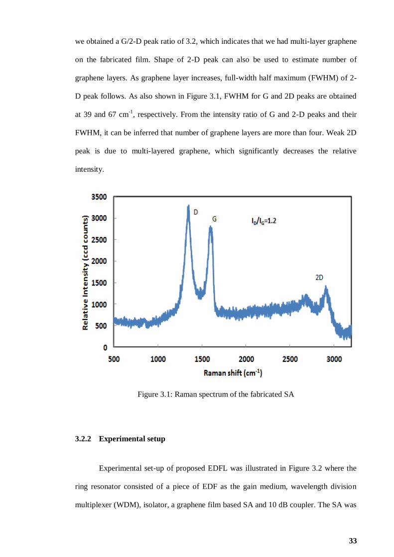
33
we obtained a G/2-D peak ratio of 3.2, which indicates that we had multi-layer graphene
on the fabricated film. Shape of 2-D peak can also be used to estimate number of
graphene layers. As graphene layer increases, full-width half maximum (FWHM) of 2-
D peak follows. As also shown in Figure 3.1, FWHM for G and 2D peaks are obtained
at 39 and 67 cm-1
, respectively. From the intensity ratio of G and 2-D peaks and their
FWHM, it can be inferred that number of graphene layers are more than four. Weak 2D
peak is due to multi-layered graphene, which significantly decreases the relative
intensity.
Figure 3.1: Raman spectrum of the fabricated SA
3.2.2 Experimental setup
Experimental set-up of proposed EDFL was illustrated in Figure 3.2 where the
ring resonator consisted of a piece of EDF as the gain medium, wavelength division
multiplexer (WDM), isolator, a graphene film based SA and 10 dB coupler. The SA was

34
fabricated by cutting a small part of the earlier prepared film (2×2 mm2) and
sandwiching it between two FC/PC fiber connectors, after depositing index-matching
gel onto the fiber ends. The measured insertion loss and modulation depth of the SA
were approximately around 2 dB and 2.6 % at 1550 nm. A 1480 nm laser diode was
used to pump the EDF via the WDM. An isolator was incorporated in the laser cavity to
ensure unidirectional propagation of oscillating laser. Output of the laser was collected
from the cavity via a 10 dB coupler which retains 90% of light in the ring cavity to
oscillate. Optical spectrum analyser (OSA, Yokogawa, AQ6370B) was used for spectral
analysis of Q-switched EDFL with a spectral resolution of 0.02 nm whereas
oscilloscope (OSC, Tektronix, TDS 3052C) was used to observe the output pulse train
of Q-switched operation via a 1GHz bandwidth photo-detector. The performance of the
laser for three different media was investigated. The media tested were 7 m long
standard silica EDF with Erbium ion concentration of 400 ppm, 4.5 m long highly
doped silica EDF with 2000 ppm Erbium ion concentration and 0.5 m long Bismuth
EDF with Erbium ion concentration of 3000 ppm.
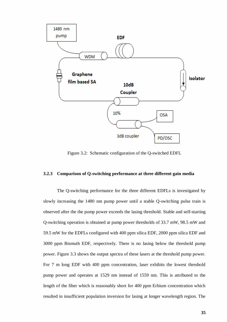
35
Figure 3.2: Schematic configuration of the Q-switched EDFL
3.2.3 Comparison of Q-switching performance at three different gain media
The Q-switching performance for the three different EDFLs is investigated by
slowly increasing the 1480 nm pump power until a stable Q-switching pulse train is
observed after the the pump power exceeds the lasing threshold. Stable and self-starting
Q-switching operation is obtained at pump power thresholds of 33.7 mW, 98.5 mW and
59.5 mW for the EDFLs configured with 400 ppm silica EDF, 2000 ppm silica EDF and
3000 ppm Bismuth EDF, respectively. There is no lasing below the threshold pump
power. Figure 3.3 shows the output spectra of these lasers at the threshold pump power.
For 7 m long EDF with 400 ppm concentration, laser exhibits the lowest threshold
pump power and operates at 1529 nm instead of 1559 nm. This is attributed to the
length of the fiber which is reasonably short for 400 ppm Erbium concentration which
resulted in insufficient population inversion for lasing at longer wavelength region. The

36
amount of Erbium ions increase by using higher concentration EDF (2000 ppm and
3000 ppm) and it absorbs the shorter wavelength photons to increase the population
inversion at 1559 nm region. Since the loss is lower at longer wavelength region, lasing
is initiated in this region which has a higher net gain. Output power is highest with
Bismuth EDF since it provides the highest gain when it is pumped by 1480 nm laser
diode. Spectral broadening is also observed especially with the silica EDF due to self-
phase modulation (SPM) effect in the ring cavity.
Figure 3.3: Optical spectrum of the Q-switched EDFLs when the pump is fixed at
threshold power
In a passively Q-switched laser, cavity loss is modulated by the SA whose
transmission/reflection depends on the light intensity. Basically, pulse is released when
the cavity energy reaches a certain value determined by the absorber saturation fluence.
Pulse repetition rate and pulse width therefore depend on the stored energy or pump
power as described in Q-switching theory. Figures 3.4 and 3.5 show the repetition rate
and pulse width, respectively against pump power for all three EDFLs. Repetition rate

37
of all Q-switched EDFLs has a monotonically increasing, near-linear relationship with
pump power. On the other hand, pulse width of all EDFLs is inversely proportional with
pump power, where the pulse duration becomes shorter as the pump power increases as
shown in Figure 3.5. For instance, when the pump power is tuned from 59.5 to 107.9
mW, pulse train repetition rate varies from 22.5 to 57.3 kHz for EDFL configured with
the Bismuth EDF. Meanwhile, pulse width of Bismuth EDFL drops from 5.01 μs to
2.48 μs. Pulse width is expected to decrease further if pump power can be augmented
beyond 107.9 mW as long as it is still kept below the damage threshold of the graphene
based SA. The shortest pulse width of 2.48 μs is obtained with the EDFL configured
with 0.5 m long Bismuth EDF. This is attributed to total cavity length used, which is
shorter than the ones in the other two EDFLs configured with silica EDF. Laser from
the 2000 ppm silica EDF displays the widest pulse width tunability whereby it can be
tuned from 12.03 μs to 4.58 μs by varying pump power from 98.5 mW to 125.0 mW.
Figure 3.4: Pulse repetition rate against pump power for the EDFL configured with
three different EDFs

38
Figure 3.5: Pulse width versus pump power for the EDFL configured with three
different EDFs
Figures 3.6 (a) - (c) show oscilloscope traces of Q-switched pulse train for
EDFLs with 400 ppm, 2000 ppm and 3000 ppm EDFs, respectively at its highest
repetition rates. There is no distinct amplitude modulation in each Q-switched envelop
spectrum, which indicates that self-mode locking effect on Q-switching is weak. The
highest repetition rate of 57.3 kHz is obtained with Bismuth EDF as pump power is
fixed at 107.9 mW. Figure 3.7 and Figure 3.8 show the average output and pulse energy,
respectively versus pump power for all EDFLs. As shown in Figure 3.7, the output
power increases linearly with pump power for all EDFLs. For instance, the average
output power of Bismuth EDFL increases from 372 μW to 788 μW as pump power
increases from 59.5 to 107.9 mW. The slope efficiencies of 0.9%, 0.6% and 0.9% are
obtained for Q-switched EDFL configured with 400 ppm, 2000 ppm and 3000 ppm,
respectively. On the other hand, pulse energy shows an increasing trend with pump
power for EDFL configured with 400 ppm EDF while the pulse energy of the two

39
highly doped EDFs exhibits the opposite trend. It is also observed that pulse energy of
EDFLs with Erbium concentrations of 400 ppm and 3000 ppm are almost constant and
difference of the maximum and minimum pulse energy is less than 3 nJ. For 2000 ppm
silica EDF, the pulse energy of the Q-switch EDFL drops from 40.69 nJ to 22.74 nJ as
pump power increases from 98.5 mW to 112 mW. This is predictable due to efficiency
of this laser is lowest as shown in Figure 3.7. This laser exhibits a slow increasing rate
of output power against pump power. However, pulse energy is directly proportional to
the ratio of output power over repetition rate. Thus, this laser shows significantly
decreasing pulse energy. Pulse energy performance of all tested lasers could be
improved by reducing insertion loss of SA and optimizing the laser cavity. The
performances of these lasers are summarized in Table 3.1.
(a)

40
(b)
(c)
Figure 3.6: Pulse train of maximum pulse repetition rate at three different gain medium
(a) Silica EDF (400 ppm) (b) Silica EDF (2000 ppm) and (c) Bismuth EDF (3000 ppm)

41
Figure 3.7: Output power against pump power for three different gain medium
Figure 3.8: Pulse energy against pump power for three different gain medium

42
Parameters Silica EDF
(400 ppm)
Silica EDF
(2000 ppm)
Bismuth EDF
(3000 ppm)
Pump Power (mW)
33.7-75.14
98.5-125
59.5- 107.9
Output Power (μW)
272-648
400-546
372-788
Pulse Energy (nJ)
11.22-14.32
22.74-40.69
13.75-16.55
Pulse Repetition rate( kHz)
24.24-47.93
9.83-24.01
22.5-57.3
Pulse Width (μs) 6.43-2.98 12.03-4.58 5.01- 2.48
Table 3.1: Summary of laser performance for three different gain media
3.3 Q-switched EDFL using a solid state Thulium-doped Fiber SA
Besides film based graphene SA, modulation of the Q-factor can also be realized
using solid-state SA fibers. The advantages of the solid-state SA fibers are their ability
to hold enormous gain excited in the gain fiber from lasing and their high damage
threshold for high-power Q-switched pulses. Only a few SA fibers have been
demonstrated in the literature, and most are for Ytterbium-doped fiber lasers (YDFLs)
(Isomäki & Okhotnikov, 2006). The energy transition 3H6 -
3F4 of Tm
3+ has a very
broad emission wavelength range, from 1.6 to 2.1 µm, and an absorption band from 1.5
to 1.9 µm. It is reported that the absorption cross section of Tm3+
doped fibers (TDFs)
are larger than the emission cross sections of EDF at 1.6 µm region, suggesting a
possible realization of a passively Q-switched EDFL using a TDF as a passive SA. In

43
this section, we have successfully demonstrated Q-switched EDFL by using a 2 m long
TDF as a SA in a ring laser cavity.
3.3.1 Configuration of the proposed Q-switched EDFL using a TDF SA
The experimental set-up of the proposed Q-switched EDFL is illustrated in Fig.
3.9, where the ring resonator consists of a 3.5 m long EDF as the gain medium, a WDM,
3 dB output coupler, polarization controller (PC) and a short piece of TDF as a SA. The
EDF used has an Erbium ion concentration of 2000 ppm, core diameter of 4 µm, mode
field diameter of 6 µm and NA of 0.24. A 1480 nm laser diode is used to pump the EDF
via the WDM. The TDF SA was a 2.0 meter long with an initial absorption loss of 6 dB
at 1570 nm, numerical aperture of 0.16 and core diameter of 2.9 µm. A PC is used to
adjust the polarization state of the oscillating light, which in turn controls the operating
wavelength of the laser. The laser light is extracted from the cavity by a 3 dB fiber
coupler which retains 50% of the light in the cavity for further oscillation. An OSA with
wavelength resolution of 0.02 nm is used to capture the output laser spectrum while a
350 MHz oscilloscope in conjunction with 1 GHz bandwidth photo-detector is used to
detect the pulse train.

44
Figure 3.9: Schematic configuration of the proposed thulium fiber based Q-switched
EDFL
3.3.2 Q-switching performance
The oscillator started to operate at Q-switching regime after reaching the
launched pump power of 20 mW. Stable self-starting Q-switched pulses were observed
as shown in Fig. 3.10 by carefully adjusting the PC when the launched pump power was
varied from 20 to 33.7 mW. However, as the pump power further increases, the pulse
train becomes unstable and disappears. As shown in Fig. 3.10, the time interval between
pulse reduces while the pulse amplitude increases as the pump power increases from 20
to 33.7 mW. The Q-switching pulse generation is due to gain-switching action provided
by the Thulium ions interaction with the oscillating Erbium laser. The high cavity loss
induced by Thulium causes large amount of energy is stored in the gain medium. When
the cavity reached the saturation state, cavity loss rapidly reduce and allow efficient
extraction of stored energy by the laser pulse. Fig. 3.11 shows the output spectra of the
EDFL with and without the TDF SA when the pump power is fixed at 33.7 mW.
Without the TDF SA we observed a stable CW operation of EDFL at 1572 nm. After

45
incorperating a 2 m long TDF inside the cavity, pulsing operation is observed. The
operating wavelength of the pulsed laser shifts to 1557.6 nm due to the cavity loss
which increases with the incorporation of TDF. The laser operates at a shorter
wavelength which has a higher gain to compensate for the loss.
Figure 3.10: Q-switched pulse evoluation of the proposed Q-switched EDFL against
pump power

46
Figure 3.11: Optical spectrum and of the proposed Q-switched EDFL when the pump is
fixed at 33.7 mW
Figure 3.12 shows how repetition rate and pulse width are related to the pump
power. The dependence of the pulse repetition rate can be seen to increase almost
linearly with the pump power, whereas the pulse width decreases also almost linearly
with the pump power. By raising the pump power into the cavity, it will speed up the
gain population excitation process to achieve the saturation state. Thus, more pulses
with narrower pulse width are generated in a same period of time. This agrees well with
the passive Q-switching theory with the passive SA. The pulse repetition rate of the Q-
switched EDFL can be widely tuned from 3.9 kHz to 12.7 kHz by varying the pump
power from 20.0 mW to 33.7 mW. On the other hand, the pulse width reduces from
20.6 μs to 7.4 μs as the pump power increases in the range of Q-switching operation. It
is observed that the pulse train becomes unstable and disappears as the pump power is
increased above 33.7 mW. This is due to the TDF SA could not recover in time after a
pulse and less gain population was excited before the next pulsing. Based on the pulse
repetition rate at the maximum pump power, the relaxation lifetime (3F4) of the thulium

47
fiber should be near and less than 0.079 ms and that was the inversion of the largest
repetition rate before the disappearing.
We also measured the average output power and calculated the corresponding
single-pulse energy. Fig. 3.13 shows the relationship of average output power and pulse
energy of the Q-switched EDFL against pump power. As shown in the figure, average
output power almost linearly increased from 180 µW to 240 µW as the pump power
increases from 20.0 mW to 33.7 mW. Besides, pulse energy exhibited decreasing trend
from 22.8 nJ to 9.4 nJ at the same pump power range. The decrement of pulse energy is
most probably due to TDF SA does not fully recover in time after a pulse and less gain
population was excited before the next pulsing. This pulse energy is relatively higher
with the previously reported carbon nanotubes based Q-switched EDFL. Energy
characteristics of the laser allow one to apply it for technological processes as marking,
trimming, micromachining etc. Moreover, it can be used in medicine due to the
relatively high absorption by biological tissue. It should be noted that the output power
and energy can be further increased through the optimization of cavity design and SA.
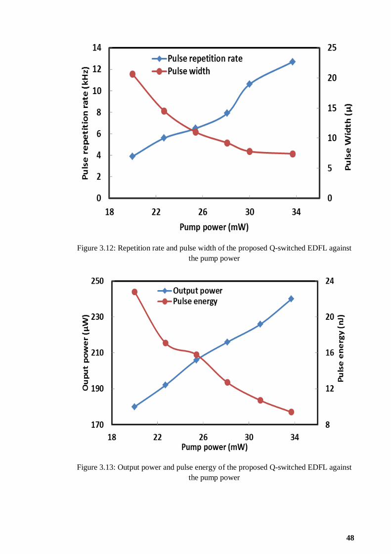
48
Figure 3.12: Repetition rate and pulse width of the proposed Q-switched EDFL against
the pump power
Figure 3.13: Output power and pulse energy of the proposed Q-switched EDFL against
the pump power
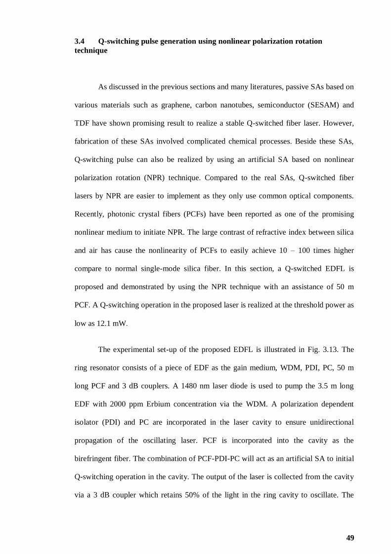
49
3.4 Q-switching pulse generation using nonlinear polarization rotation
technique
As discussed in the previous sections and many literatures, passive SAs based on
various materials such as graphene, carbon nanotubes, semiconductor (SESAM) and
TDF have shown promising result to realize a stable Q-switched fiber laser. However,
fabrication of these SAs involved complicated chemical processes. Beside these SAs,
Q-switching pulse can also be realized by using an artificial SA based on nonlinear
polarization rotation (NPR) technique. Compared to the real SAs, Q-switched fiber
lasers by NPR are easier to implement as they only use common optical components.
Recently, photonic crystal fibers (PCFs) have been reported as one of the promising
nonlinear medium to initiate NPR. The large contrast of refractive index between silica
and air has cause the nonlinearity of PCFs to easily achieve 10 – 100 times higher
compare to normal single-mode silica fiber. In this section, a Q-switched EDFL is
proposed and demonstrated by using the NPR technique with an assistance of 50 m
PCF. A Q-switching operation in the proposed laser is realized at the threshold power as
low as 12.1 mW.
The experimental set-up of the proposed EDFL is illustrated in Fig. 3.13. The
ring resonator consists of a piece of EDF as the gain medium, WDM, PDI, PC, 50 m
long PCF and 3 dB couplers. A 1480 nm laser diode is used to pump the 3.5 m long
EDF with 2000 ppm Erbium concentration via the WDM. A polarization dependent
isolator (PDI) and PC are incorporated in the laser cavity to ensure unidirectional
propagation of the oscillating laser. PCF is incorporated into the cavity as the
birefringent fiber. The combination of PCF-PDI-PC will act as an artificial SA to initial
Q-switching operation in the cavity. The output of the laser is collected from the cavity
via a 3 dB coupler which retains 50% of the light in the ring cavity to oscillate. The

50
OSA is used for spectral analysis of the Q-switched EDFL whereas oscilloscope is used
to observe the output pulse train of the Q-switched operation via a 1 GHz bandwidth
photo-detector.
Figure 3.14: Schematic configuration of the proposed Q-switched EDFL
In this experiment, Q-switching pulse generation is self-started at a very low
threshold power of 12.1 mW. However, this pulse starts to disappear as the pump power
is increased above 15.1 mW. The pulse evolution against pump power is shown in Fig.
3.15. As shown in the figure, the pulse repetition rate increases with the increment of
pump power. Fig. 3.16 shows the output spectrum of the Q-switched EDFL at pump
power of 12.1 mW. It is shown that Q-switched laser also produces an unstable
amplitude lines with free spectral range (FSR) of 0.48 nm, which is most probably due
to the longitudinal modes interference in the laser cavity. FSR of 0.48 nm is determined
by the length and the effective group indices of the PCF. The unstable multi-wavelength
generation is due to the intensity dependent loss induced by NPR. The role of PCF is to

51
increase the nonlinear effect as well as to constitute an inline periodic filter with the
PDI.
Figure 3.15: Pulse evolution of the proposed Q-switched EDFL against pump power
Figure 3.16: Optical spectrum for the Q-switched EDFL at threshold pump power

52
Fig. 3.17 shows how an average output power and pulse energy of the Q-
switched EDFL when varied with the pump power. As shown in the figure, average
output power increases almost linearly increased from 12.5 µW to 58.0 µW as the
pump power increases from 12.1 mW to 15.1 mW. The pulse energy also increased
from 9.0 nJ to 12.4 nJ as the pump power increases from 12.1 mW to 15.1 mW. Fig.
3.18 shows the relation between repetition rate and pulse width with the pump power.
Pulse repetition rate can be seen to increase almost linearly with the increment of pump
power, while the pulse width shows decreasing trend with the pump power. The pulse
repetition rate of the Q-switched EDFL can be tuned from 1.4 kHz to 4.7 kHz by
increasing the pump power from 12.1 mW to 15.1 mW. On the other hand, the pulse
width reduces from 20.6 μs to 5.1 μs as the pump power increases in the range of Q-
switching operation. The combination of PC-PDI-PCF acted as a SA based on the NPR
effect. With proper adjustment of PC, the cavity loss can reach a higher level. Lasing
radiation was too weak to pass through the PDI and PCF which act as polarizer in the
cavity. Hence, a mass of inverted populations was accumulated at the upper energy
level in the EDF. When the accumulation reached a sufficient level, the lasing radiation
became strong enough to propagate through the polarizer. Then, the inverted
populations in EDF exhausted abruptly and cavity loss became too high to allow the
lasing radiation to propagate through. Therefore, the Q-switched pulse train was formed.
Erbium ion saturation time can be further decreased with a higher pump power,
provided that the erbium ion life time is much longer than the round trip time in the
cavity. As shown in Fig. 3.18, the pulse repetition rate is directly proportional to the
pump power, which is well agreed with NPR Q-switching theory. Moreover,
accumulation rate and exhaustion rate of inverted populations in EDF increased with the
increment of pump power. Hence, pulse width behaves inversely proportion to pump
power as shown in Fig. 3.18.

53
Figure 3.17: Output power and pulse energy of the proposed Q-switched EDFL against
pump power
Figure 3.18: Repetition rate and pulse width of the proposed Q-switched EDFL against
pump power

54
3.5 Multi-wavelength Q-switched Generation With Graphene Based SA
Both multi-wavelength and Q-switched EDFLs have wide applications in optical
communications, sensors and instrumentations. Multi-wavelength laser can be achieved
at room temperature by using various methods such as cascaded stimulated Brillouin
scattering (Fok & Shu, 2006) and four-wave mixing (FWM) (Han et al., 2006).
Recently, nonlinear polarization rotation (NPR) technique is also proposed for multi-
wavelength generation based on intensity dependent loss in the cavity (Feng, Tam, &
Wai, 2006). On the other hand, a Q-switched EDFL has been successfully demonstrated
by using a graphene based SA as described in section 3.2. It was observed that the Q-
switching performance is superior especially in terms of pulse energy with the use of
highly doped silica-based EDF (2000 ppm) as gain medium compared to that of other
fibers. In this section, a Q-switched multi-wavelength EDFL is demonstrated by
integrating a graphene SA in an EDFL cavity comprising an additional nonlinear gain
medium. The SA is obtained by sandwiching the graphene film between two fiber
connectors. 50 m long PCF is used as the nonlinear gain medium to activate the NPR
effect and thus allows the generation of a stable multi-wavelength pulse train.
The experimental set-up of the proposed multi-wavelength Q-switched EDFL is
illustrated in Figure 3.19. The ring resonator consists of a 4.5 m long EDF as the gain
medium, WDM, PDI, PC, 50m long PCF, a graphene-based SA and 10 dB output
coupler. A 1480 nm laser diode is used to pump the EDF via the WDM. A PDI and PC
are incorporated in the laser cavity to ensure unidirectional propagation of the
oscillating laser and to act as a polarizer. A PC was also utilized to tune the polarization
state of light in the laser cavity. The output of the laser is collected from the cavity via a
10 dB coupler which retains 90% of the light in the ring cavity to oscillate. The OSA is

55
used for the spectral analysis while the oscilloscope is used to observe the output pulse
train via a photodetector.
Figure 3.19: Schematic configuration of the proposed multi-wavelength Q-switched
EDFL
To realize the multi-wavelength Q-switched lasing operation, the laser cavity
must have two important components; interferometer and SA. The interferometer
functions to generate multiple resonance peaks for multi-wavelength generation while
SA with a wideband optical absorption range is required to provide saturable
absorption, which covers all the multi-wavelength region. In this work, a stable multi-
wavelength laser with Q-switching operation was obtained as the pump power reaches
the threshold pump power of 39.6 mW with a proper tuning of PC. Figures 3.20 (a) and
(b) show the output optical spectrum and the typical pulse train of the proposed multi-
wavelength Q-switched EDFL respectively, when the pump is fixed at the threshold
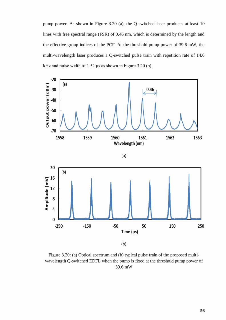
56
pump power. As shown in Figure 3.20 (a), the Q-switched laser produces at least 10
lines with free spectral range (FSR) of 0.46 nm, which is determined by the length and
the effective group indices of the PCF. At the threshold pump power of 39.6 mW, the
multi-wavelength laser produces a Q-switched pulse train with repetition rate of 14.6
kHz and pulse width of 1.52 μs as shown in Figure 3.20 (b).
(a)
(b)
Figure 3.20: (a) Optical spectrum and (b) typical pulse train of the proposed multi-
wavelength Q-switched EDFL when the pump is fixed at the threshold pump power of
39.6 mW

57
The multi-wavelength generation can be described as follows. The light is split
into two orthogonal modes, which experience different nonlinear phase shift as they
propogates inside the PCF owing to the Kerr effect. Then the polarization orientation of
the light rotates in the PCF with the angle of rotation is correlative with the light
intensity. The signal passes through the PDI, which the transmittivity is dependent on
the rotation of the polarization or the oscillating light intensity. The combination of the
PCF and PDI functions an intensity equalizer, which produces an intensity dependent
inhomogeneous loss and thus elleviates the mode-competition. As a result, the balance
between the inhomogeneous loss induced by NPR and the mode competition effect of
the EDF can lead to a stable multiwavelength oscillations. When the polarization state is
selected properly by adjusting the PC, multi-wavelength laser can be easily obtained as
shown in Figure 3.20. Figure 3.21 shows the evolution of the output spectra against the
pump power. As shown in the figure, the number of lines and its peak power increases
with the pump power. However, the wavelength spacing is maintained at 0.46 nm for all
pump powers.
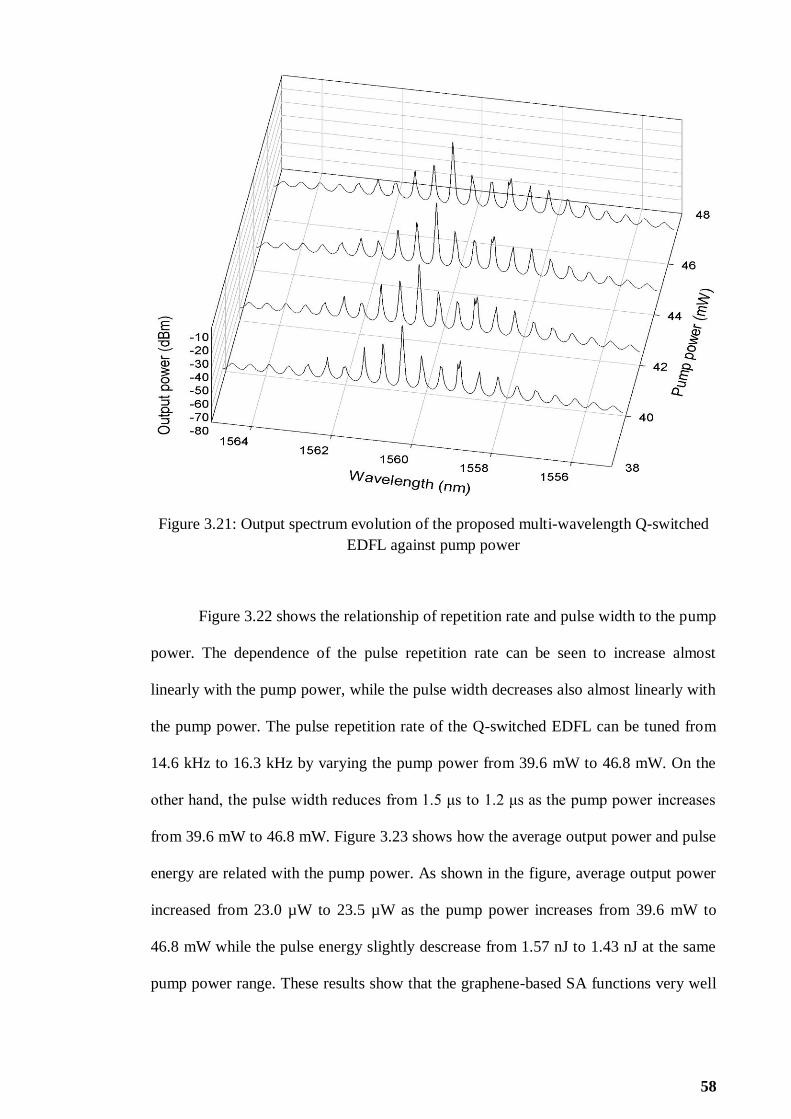
58
Figure 3.21: Output spectrum evolution of the proposed multi-wavelength Q-switched
EDFL against pump power
Figure 3.22 shows the relationship of repetition rate and pulse width to the pump
power. The dependence of the pulse repetition rate can be seen to increase almost
linearly with the pump power, while the pulse width decreases also almost linearly with
the pump power. The pulse repetition rate of the Q-switched EDFL can be tuned from
14.6 kHz to 16.3 kHz by varying the pump power from 39.6 mW to 46.8 mW. On the
other hand, the pulse width reduces from 1.5 μs to 1.2 μs as the pump power increases
from 39.6 mW to 46.8 mW. Figure 3.23 shows how the average output power and pulse
energy are related with the pump power. As shown in the figure, average output power
increased from 23.0 µW to 23.5 µW as the pump power increases from 39.6 mW to
46.8 mW while the pulse energy slightly descrease from 1.57 nJ to 1.43 nJ at the same
pump power range. These results show that the graphene-based SA functions very well

59
as a typical SA to achieve the Q-switching while the highly nonlinearity of PCF has
succesfully induced NPR in the cavity to achieve multi-wavelength operation.
It should be noted that no Q-switched operation occurs without the graphene SA
connected in the laser cavity. It is clear that the Q-switched operation is mainly induced
by the SA. By removing the SA from the set-up, an unstable multi-wavelength laser
with continuous wave operation is observed. Thus, we strongly believed that the
incorporation of SA also improves the stability of the multi-wavelength lasing due to
the nonlinearity of graphene-based SA that can induce both NPR and FWM effects in
the laser cavity. The FWM effect functions to stabilize the multi-wavelength operation.
The stability of the multi-wavelength laser is also investigated by monitoring the
spectrum evolution of the laser against time at the threshold pump power of 39.6 mW as
shown in Figure 3.24. In the experiment, the output spectrum is repeatedly scanned for
every 5 minutes. As shown in the figure, the multi-wavelength Q-switched EDFL lases
stably with power fluctuations of less than 1 dB over 20 minutes. It shows the
combination of PCF with PDI and PC produces a very stable multi-wavelength laser
based on the NPR mechanism.

60
Figure 3.22: Repetition rate and pulse width of the proposed multi-wavelength Q-
switched EDFL against pump power
Figure 3.23: Output power and pulse energy of the proposed multi-wavelength Q-
switched EDFL against pump power

61
Figure 3.24: Output spectrum evolution of the proposed multi-wavelength Q-switched
EDFL against time
3.6 Summary
In this chapter, three passive techniques for generating Q-switching pulse have
been evaluated and demonstrated; graphene film based SA, solid state TDF SA and
NPR. It is found that the NPR based Q-switching operation occurs at a relatively lower
pump power of around 12 mW compared to other Q-switching techniques. Other
techniques require higher pump power to initiate Q-switching operation mainly due to
the device loss. For instance, Q-switched EDFLs based on graphene and solid state TDF
SA has a threshold pump power in a range of 20 mW and 33 mW respectively. The
NPR based Q-switched EDFL requires a lower pump power to initiate Q-switching due
62
to the incorporation of high nonlinearly of PCF, which induces sufficient phase shift in
low pump power.
NPR technique proved its multi-functional operation to achieve both Q-switched
and multi-wavelength operation. Furthermore, NPR also offers advantages such as
tunable saturable absorption strength and ease of implementation with only
conventional optical fiber components. Even though SAs can produce more stable Q-
switched under laboratory environmental condition, but SAs are easily damage under
high power operation. Since NPR technique is highly rely on the light polarization in
the laser cavity, readjustment of polarization state is required in order to maintain the Q-
switched operation whenever there is vibration or temperature fluctuation. However, the
uncertainty of vibration and temperature fluctuation can be well controlled under
laboratory environmental condition. Besides the advantages above, NPR technique
exhibits a high potential to obtain different types of pulsed laser by only changing the
polarization state. With these crucial advantages, NPR technique is chosen to be the
most suitable method for further investigation in different type of pulsed laser. Several
types of pulsed laser such as mode-locked and dark pulse are investigated in the
following two chapters via NPR method.

63
CHAPTER 4
DEVELOPMENT OF PASSIVE MODE-LOCKED ERBIUM-
DOPED FIBER LASERS
4.1 Introduction
Passively mode-locked fiber lasers are attractive for many applications because
of their simplicity, compactness, efficient heat dissipation, and ability to generate high-
quality pulses (Laubereau & Kaiser, 1974). For instance, mode-locked Erbium-doped
fiber lasers (EDFLs), which are capable of generating ultra-short pulses in the
telecommunication wavelength of about 1.55 μm, have promising applications in the
next generation telecommunication systems (Kaiser & Huttl, 2007). Generation of ultra-
short pulses has also attracted considerable attention in other areas of physics such as
the ultrafast physics and nonlinear optics. The passively mode-locked lasers work by
inducing a stable phase relationship between the longitudinal modes of the laser cavity.
Under the optimum fixed-phase condition, interference between these modes produces
stable ultra-short pulses. Among the different types of passively mode-locked
techniques, nonlinear polarization rotation (NPR) has gained the significant interests in
recent years. This is attributed to the NPR implementation, which can easily tune the
phase shift in a laser cavity and thus different type of fix-phase condition in a laser
cavity can be easily achieved.
In this chapter, several passively mode-locked fiber lasers are demonstrated
using the NPR technique. At first, the mode-locked EDFL with three switchable
operation states is proposed and demonstrated. Next, square pulse emission with ultra-
low repetition rate is proposed and demonstrated by using long laser cavity. Finally, a

64
multi-wavelength mode-locked fiber laser is proposed and demonstrated using a figure-
of-eight configuration.
4.2 NPR based mode-locked EDFL with three switchable operation states
Mode-locked EDFLs normally operates in the negative net cavity dispersion
regime, where the nonlinear Kerr effect naturally balances the group velocity dispersion
(GVD) of the cavity. This NPR effect results in the formation of stable soliton pulses
with sub-picosecond pulse width. Other types of pulses such as stretched pulse (Haus et
al., 1995), self-similar pulse (Renninger, Chong, & Wise, 2010), and dissipative soliton
(DS) (Wu et al., 2009) have also been obtained successively in the recent years using
the NPR technique. DSs have been investigated in large- or all-normal dispersion
regime previously (Liu, 2009). It was found that the cavity gain and loss play essential
roles in the formation of DSs, where various operation regimes can be realized by
controlling both parameters. In this section, we experimentally demonstrate a new NPR
based mode-locked EDFL which is capable to generate dissipative soliton pulse with
switchable repetition rate. The EDFL operates in anomalous dispersion region. Three
switchable operation states are obtained by varying the pump power and without
disturbing the polarization state. The proposed laser generates nanosecond and
microsecond pulses, where their energy can be easily amplified by the optical
amplifiers. Such optical pulses could have many potential applications such as in laser
range-finder and fiber sensors systems.

65
4.2.1 Experimental setup
The experimental setup of the mode-locked EDFL with switchable repetition
rate is shown in Figure 4.1. The EDFL uses a ring configuration with a cavity length of
about 6.9 km. A 3.5 m long EDF with doping concentration of 2000 ppm and group
velocity dispersion (GVD) parameter of about -21.64 (ps/nm)/km was used as the gain
fiber. The other fibers in the cavity are a 6.9 km long dispersion compensation fibers
(DCFs) with GVD of about -4 (ps/nm)/km and a standard SMF, which constituted the
rest of the ring. The cavity operates in large positive GVD where the net dispersion and
fundamental repetition rate are estimated at −0.073 ps2 and 29.0 kHz, respectively. The
NPR technique was adopted for achieving the mode locking and thus a fiber pigtailed
polarization dependent isolator (PDI) together with an inline polarization controller was
employed to control the polarization of light in the cavity. The PDI is also used to
ensure the unidirectional operation of the ring. The EDF was pumped by a 1480 nm
laser diode through a wavelength-division-multiplexing (WDM) coupler. A 3dB fiber
coupler was used to tap out the laser emission. All the components (isolator, WDM and
fiber output coupler) in the resonator were made from standard SMF. An optical
spectrum analyzer (OSA, Yokogawa, AQ6370B) and a 350MHz oscilloscope
(Tektronix TDS 3052C) together with a 1 GHz photo-detector were used to
simultaneously monitor the spectrum and output pulse train of the laser.

66
Figure 4.1: Schematic configuration of the mode-locked EDFL
4.2.2 Comparison of the three different mode-locked operation states
A major difference of the current fiber laser from those reported previously is
that a long cavity was used, which increases the total normal cavity dispersion. Mode
locking of the laser is always self-started, and depending on the pump strength, various
modes of laser operation were observed, including fundamental and harmonic
dissipative soliton. In particular, under low pumping power a stable square pulse
emission mode was also observed. The square pulse trains is self-started at threshold
pump power of 17.5 mW and transforms to fundamental dissipative soliton as the pump
power increases above 34.3 mW. Figure 4.2 shows the typical oscilloscope traces of the
observed square pulse emission at two different pump power of 17.5 and 34.3 mW.
Both pulse trains have a repetition rate of 87.0 kHz, which indicates that the laser
generates a third-order harmonic pulse. Inset of Figure 4.2 illustrates an envelope of a
single pulse, which shows a rectangular pulse with a steep rising and falling edges. The
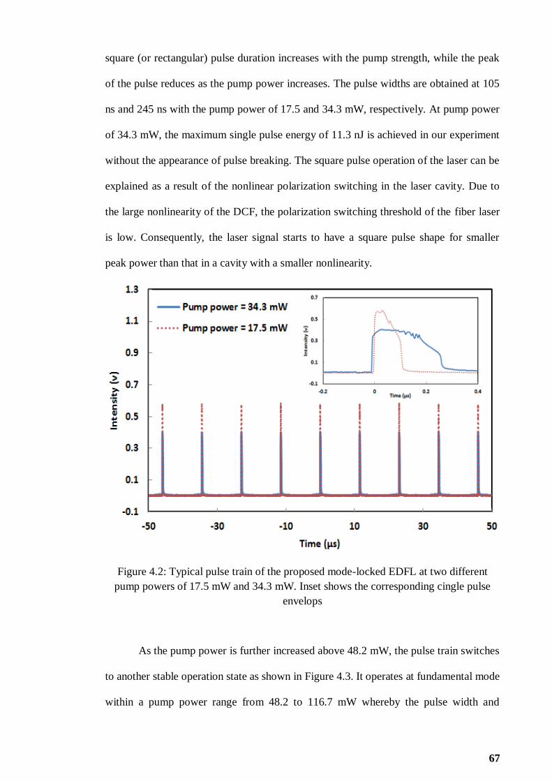
67
square (or rectangular) pulse duration increases with the pump strength, while the peak
of the pulse reduces as the pump power increases. The pulse widths are obtained at 105
ns and 245 ns with the pump power of 17.5 and 34.3 mW, respectively. At pump power
of 34.3 mW, the maximum single pulse energy of 11.3 nJ is achieved in our experiment
without the appearance of pulse breaking. The square pulse operation of the laser can be
explained as a result of the nonlinear polarization switching in the laser cavity. Due to
the large nonlinearity of the DCF, the polarization switching threshold of the fiber laser
is low. Consequently, the laser signal starts to have a square pulse shape for smaller
peak power than that in a cavity with a smaller nonlinearity.
Figure 4.2: Typical pulse train of the proposed mode-locked EDFL at two different
pump powers of 17.5 mW and 34.3 mW. Inset shows the corresponding cingle pulse
envelops
As the pump power is further increased above 48.2 mW, the pulse train switches
to another stable operation state as shown in Figure 4.3. It operates at fundamental mode
within a pump power range from 48.2 to 116.7 mW whereby the pulse width and

68
repetition rate of the generated dissipative soliton are maintained at 8.5 μs and 29 kHz
respectively, throughout the pump power range. It is also observed that the average
output power of the laser increases from 1.27 mW to 3.84 mW as pump power increases
from 48.2 mW to 116.7 mW. Besides, pulse energy exhibits increasing trend from 43.5
nJ to 131.5 nJ in the same pump power range. When the pump power continues to
increase beyond 116.7 mW, the pulse train experiences unstable oscillation before it
reaches another stable operation state at pump power of 138.9 mW. Figure 4.4 shows
the typical pulse train at two different pump powers of 138.9 and 145.0 mW. Within the
pump power range, the laser operates in harmonic mode with a fixed pulse width and
pulse repetition rate of 2.8 μs and 58 kHz respectively. As the pump power is increased
from 138.9 mW to 145 mW, the output power increases from 5.9 mW to 6.2 mW while
pulse energy improves from 101 nJ to 106.5 nJ. It was shown that the long-cavity laser
can generate three different pulses in the same laser cavity. The interaction and
evolution of multiple pulses in mode-locked fiber lasers are attributed to the phase shift,
which corresponds to the instantaneous frequency at pulse peak to be nonzero.

69
Figure 4.3: Typical pulse trains of the mode-locked EDFL at pump powers of 48.2 mW
and 116.7 mW, which operate at fundamental mode
Figure 4.4: Pulse train obtained from proposed EDFL with pump power of 138.9 mW
and 145 mW
70
Figure 4.5 shows the output spectrum of the mode-locked EDFL at different
pump powers. The laser operates at a center wavelength of 1568 nm and the evolution
of the output spectrum with the pump power can be explained by NPR phenomena. By
adjusting the PC, the linear polarized light changes to elliptically polarized light. The
elliptically polarized light splits into two orthogonal modes and experience different
nonlinear phase shift as it propagates through DCF and EDF owing to Kerr effect. The
direction of elliptically polarized light rotates due to the intensity difference. Rotated
degree for central part of noise pulse can be different with leading and trailing edges.
When it passes through PDI, only the central part can pass through with a low loss,
whereas the leading and trailing edges are blocked. After many round trips, square pulse
generation can be observed especially at a lower pump power. The square pulse
duration increases with the pump strength. As shown in Figure 4.5, the optical spectrum
has no characteristic sharp spectral edges as that of the dissipative solitons, but
resembles that of the amplified spontaneous emission (ASE) of the EDF with the
spectral centre shifted to the longer wavelength side. It is also found that the proposed
laser here works on the stable operation when the pump power is from 17.5 to 34.3 mW,
48.2 to 116.7 mW, and 138.9 to 145.0 mW, respectively. In the other regime, the laser
works unstably. So this laser alternately evolves on the stable and unstable mode-
locking states as a function of the pump strength.

71
Figure 4.5: Optical spectrum of the mode-locked laser at various pump powers
4.3 Mode-locked square pulse emission with ultra-low repetition rate
Resonator with kilo-meters long offers lower fundamental repetition rate in the
kilo-Hertz and hence allow the deliverance of higher pulse energy. However, there is a
challenge that needs to be overcome if the oscillator is long. The combined action of
both Kerr nonlinearity and dispersion generally leads to pulse break up (multi-pulse)
after the accumulated nonlinear phase has exceeded a certain level. Pulse breaking
leads to higher repetition rate and lower pulse energy compared to single pulse
operation. Apart from the DS with steep spectral edges, a new approach, namely the
dissipative soliton resonance (DSR) (Chang et al., 2008) has been suggested capable to
increase the pulse energy from a fiber laser. The formation of DSR is based on certain
parameters selection within the frame of complex Ginzburg-Landau Equation (CGLE)
equation where its pulse energy can be increased infinitely. DSR is recognized as square
pulse with flat top and steep edges and thus its pulse duration is rather broad. In this
72
section, nano-second DSR square pulse generation with an ultra-low repetition rate of
10.2 kHz is demonstrated by inserting a 20 km long SMF in a simple EDFL‟s ring
resonator. It is worth noting that although the cavity length is significantly long, the
fiber laser still operates at its fundamental repetition rate without pulse breaking. By
manipulating the polarization state in the cavity, the proposed laser can also be adjusted
to operate in harmonic mode.
4.3.1 Configuration of the proposed mode-locked square pulse EDFL
The experimental setup of the proposed mode-locked fiber laser is schematically
shown in Figure 4.6. It uses a 4.5 m long EDF with an erbium concentration of 2000
ppm, cut-off wavelength of 910 nm, a pump absorption coefficient of 24 dB/m at 980
nm and a dispersion coefficient of -21.64 ps/nm∙km at λ = 1550 nm, as the gain
medium. The EDF is pumped with a 1480 nm laser diode through a 1480/1550 nm
WDM. A PDI is used to ensure unidirectional propagation of light in the cavity and at
the same time to generate linear light polarization. A PC is employed to adjust the
polarization of light. A 20 km spool of SMF constitutes the long cavity and also serves
to increase the nonlinearity and dispersion. The dispersion parameter of the SMF is 17
ps/nm∙km. 50% of the circulating light is taken out of the cavity via a 3 dB coupler and
then fed into another 3 dB coupler. The second coupler splits the light for simultaneous
monitoring, one part into an OSA and the other into an oscilloscope (OSC) and Radio
Frequency Spectrum Analyzer (RFSA) together with a high speed photo-detector. The
cavity is operating in a large negative dispersion region due to the long SMF

73
Figure 4.6: Experimental set-up of the proposed DSR laser
4.3.2 Mode-locked square pulse performance
The mode-locked laser is generated based on NPR effect in the ring cavity. The
polarizing isolator placed besides the PC acts as the mode-locking element in the
proposed laser. It plays the double role of an isolator and a polarizer such that light
leaving the isolator is linearly polarized. Consider a linearly polarized pulse just after
the isolator. The polarization state evolves nonlinearly during the propagation of the
pulse inside the EDF and SMF due to SPM and cross phase modulation (XPM) effects
in the ring cavity. The state of polarization is non-uniform across the pulse because of
the intensity dependence of the nonlinear phase shift. The PC is adjusted so that it forces
the polarization to be linear in the central part of the pulse. The polarizing isolator lets
the central intense part of the pulse pass but blocks (absorbs) the low-intensity pulse
wings. The net result is that the pulse is slightly shortened after one round trip inside the

74
ring cavity, an effect identical to that produced by a fast saturable absorber. In other
words, the PDI, working together with the birefringence fibers generates an intensity
dependent loss mechanism in the cavity that contributes to mode-locked square pulse
generation in the cavity.
In this experiment, by careful adjustment of the PC, stable square pulse starts to
form at pump power of 108 mW. Figure 4.7 shows the optical spectrum of the typical
square pulse emission from the laser at three different pump powers of 108 mW, 112
mW and 125 mW. At the maximum pump power of 125 mW, the laser operates at
1568.7 nm with the peak power of -17.2 dBm and 3 dB bandwidth of about 1 nm.
Figure 4.8 shows the oscilloscope trace of a square pulse train. The pulse train has an
ultra-low repetition rate at 10.2 kHz as determined by the cavity length. Figure 4.9
focuses on a single pulse envelop at two different pump powers. As shown in the figure,
the square pulse has distinct characteristic of steep leading and trailing edges and its
pulse width can be tuned by changing the pump power. At 120 mW, the measured pulse
width is 120.0 ns while at 125 mW pump power, the pulse width increases to 167.7 ns.
At the maximum pump power, the pulse still has a square shape while keeping the peak
power almost constant. With the orientations of the wave-plates fixed, it is observed that
the peak power of the square pulse is maintained while the pulse width increases with
pump power. The ripple structures on the top of the pulse are probably due to
insufficient gain to compensate for the loss in the ultra-long cavity. A cleaner square
pulse structure is expected at higher pump power.
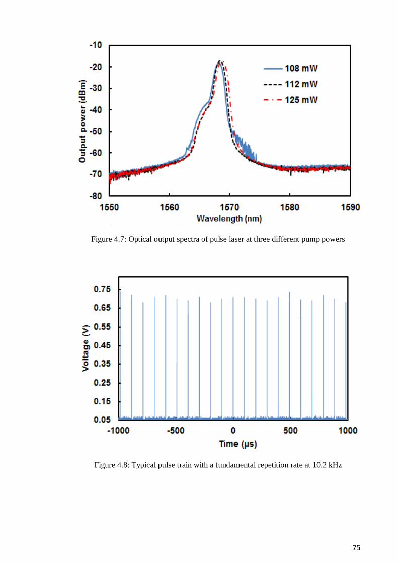
75
Figure 4.7: Optical output spectra of pulse laser at three different pump powers
Figure 4.8: Typical pulse train with a fundamental repetition rate at 10.2 kHz
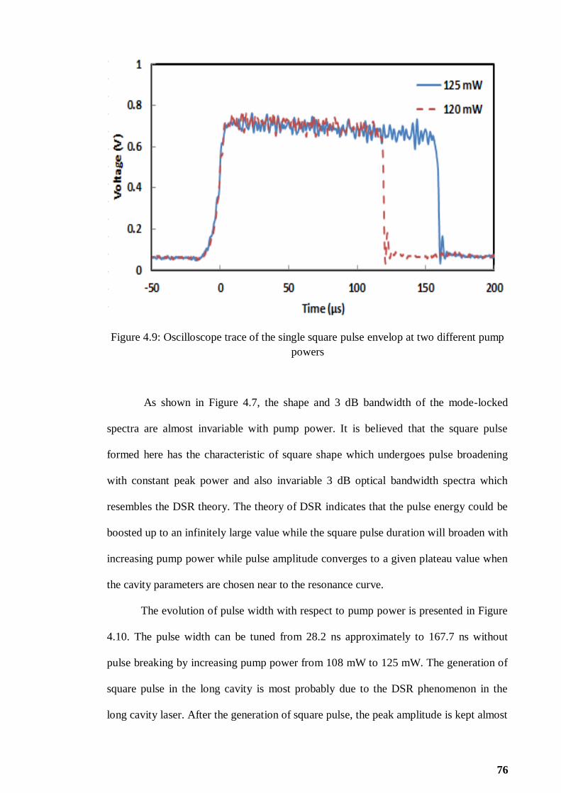
76
Figure 4.9: Oscilloscope trace of the single square pulse envelop at two different pump
powers
As shown in Figure 4.7, the shape and 3 dB bandwidth of the mode-locked
spectra are almost invariable with pump power. It is believed that the square pulse
formed here has the characteristic of square shape which undergoes pulse broadening
with constant peak power and also invariable 3 dB optical bandwidth spectra which
resembles the DSR theory. The theory of DSR indicates that the pulse energy could be
boosted up to an infinitely large value while the square pulse duration will broaden with
increasing pump power while pulse amplitude converges to a given plateau value when
the cavity parameters are chosen near to the resonance curve.
The evolution of pulse width with respect to pump power is presented in Figure
4.10. The pulse width can be tuned from 28.2 ns approximately to 167.7 ns without
pulse breaking by increasing pump power from 108 mW to 125 mW. The generation of
square pulse in the long cavity is most probably due to the DSR phenomenon in the
long cavity laser. After the generation of square pulse, the peak amplitude is kept almost
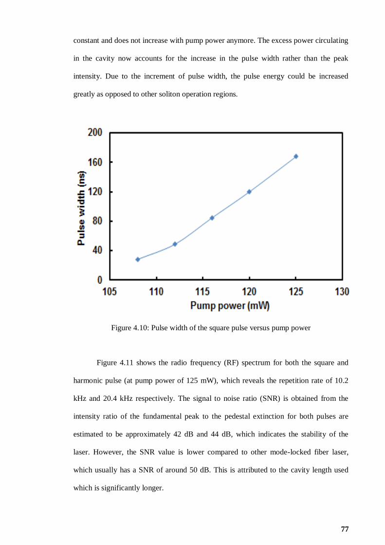
77
constant and does not increase with pump power anymore. The excess power circulating
in the cavity now accounts for the increase in the pulse width rather than the peak
intensity. Due to the increment of pulse width, the pulse energy could be increased
greatly as opposed to other soliton operation regions.
Figure 4.10: Pulse width of the square pulse versus pump power
Figure 4.11 shows the radio frequency (RF) spectrum for both the square and
harmonic pulse (at pump power of 125 mW), which reveals the repetition rate of 10.2
kHz and 20.4 kHz respectively. The signal to noise ratio (SNR) is obtained from the
intensity ratio of the fundamental peak to the pedestal extinction for both pulses are
estimated to be approximately 42 dB and 44 dB, which indicates the stability of the
laser. However, the SNR value is lower compared to other mode-locked fiber laser,
which usually has a SNR of around 50 dB. This is attributed to the cavity length used
which is significantly longer.

78
(a)
(b)
Figure 4.11: RF spectrum of the generated pulses: (a) square pulse and (b) harmonic
pulse

79
The square pulse can be switched to harmonic pulse operating in micro-second
region by careful adjustment of the PC while maintaining all other cavities‟ parameters.
Self-starting harmonic mode-locking can be realized by an appropriate adjustment of
polarization of light and at an adequate pump power. When pump power is raised to
approximately 100 mW, mode-locked pulse is formed with repetition rate of 10.2 kHz
which corresponds to the fundamental frequency.
As the pump power is increased to 108 mW, pulse breaking is observed where
its repetition rate doubles to 20.4 kHz, representing the second harmonic order pulse.
Harmonic mode-locking is regarded as a phenomenon when a single circulating pulse
breaks into multiple pulses with constant temporal spacing. This technique is often
adopted for high repetition rates in multi-GHz fiber lasers. The typical pulse train of the
mode-locked fiber laser is shown in Figure 4.12 for two different pump powers of 100
mW and 108 mW. The attainable pulse widths are 14.2 µs and 8.1 µs at 100 mW and
108 mW, respectively. The optical spectrum of the harmonic pulse is illustrated in
Figure 4.13 when the pump power is set at 125 mW. As shown in the figure, the
harmonic laser operates at 1569.36 nm with peak output power of -18.4 dBm and 3 dB
bandwidth of 1.7 nm.

80
(a)
(b)
Figure 4.12: Typical pulse train of the mode-locking pulse at two different pump
powers: (a) 100 mW and (b) 108 mW

81
Figure 4.13: Output spectrum of the harmonic mode-locked EDFL
Figure 4.14 depicts the relationship between the output power and pump power
for both DSR and harmonic pulses obtained from the proposed mode-locked EDFL of
Figure 4.6. The output power is measured at the 50% port of second 3 dB coupler which
channels the output light into OSA. It is observed that the output power increases
linearly with pump power for both lasers. As expected, the square pulse recorded higher
output power compared to harmonic pulse. The output power for square pulse varies
from 2.19 mW to 2.54 mW as the pump power increases from 108 mW to 125 mW. On
the other hand for harmonic pulse, the highest measured output power is 2.39 mW at
125 mW. Figure 4.15 shows how the pulse energy changes with the increment of pump
power for both lasers. Both square and harmonic pulses exhibit relatively high pulse
energy in the nano-Joule range due to the long cavity length used in the laser setup.
Pulse energy of both lasers is found to be increasing with pump power. By increasing
the pump power from 108 mW to 125 mW, the pulse energy increases in a range of
215.3 nJ to 249.8 nJ and 0.215 pJ to 0.249 pJ for the square and harmonic pulse,

82
respectively. It is observed that the pulse energy reduces drastically from 188.7 nJ (100
mW) to 100 nJ (108 mW) as the fundamental pulse breaks into the second harmonic
order pulse. When the fundamental pulse breaks, the repetition rate doubles from 10.2
kHz to 20.4 kHz. This will reduce the pulse energy as the pulse energy is inversely
proportional to repetition rate. Consequently, the pulse energy of square pulse can be
further increased by optimizing the laser parameters and employing higher pump power.
Figure 4.14: Measured output power for square and harmonic pulse at various pump
powers

83
Figure 4.15: Pulse energy of produced pulse for square and harmonic pulse
The maximum attainable pulse energy for the square pulse is higher than second
harmonic pulse by 53.1%. Lower pulse energy is observed for harmonic pulse due to the
occurrence of pulse breaking phenomena where a single pulse breaks into many pulses;
two pulses in this experiment. After a single pulse is formed and traverses in the cavity,
it encounters high nonlinear effects and dispersion, introduced by the long SMF. A
single pulse will break into many pulses where overtaking of different parts of a pulse
will lead to optical wave breaking. It can be concluded that a laser should remain single
pulse operation in order to realize high pulse energy. Square pulse which has steeper
leading and trailing edges along with flat top in the temporal domain can withstand
pulse breaking compared to the Gaussian or sech2 shape pulse. This can be presumed
that the square pulse has very low frequency chirps across the central region of pulse
and has nonlinear pulse chirping at the pulse edges. The nonlinear chirp at the pulse
edges can resist the dispersion and nonlinearity effects in the cavity and thus can

84
maintain its wave breaking free pulse. Neither square pulse nor harmonic pulse is
observed when the 20 km long SMF is removed. Without the long SMF, only the
conventional pulse with Kelly side-bands is obtained. The insertion of 20 km long SMF
brings the cavity‟s parameter near to the resonance curve, thereby producing wave
breaking free square pulse. From the experimental results, the laser operates in two
different operating regimes; harmonic and square pulse by changing the pump power
and also the polarization of light. The change of light polarization leads to different
saturable absorption strength and intrinsic spectral filtering which affects the intra-
cavity nonlinear gain and transmittivity. As a result, various kinds of pulse shapes can
be formed. Both square and harmonic pulses generated by the mode-locked EDFL are
stable. If there is no perturbation introduced to the laser, both square and harmonic pulse
EDFL can last several hours under normal laboratory condition.
4.4 Multi-wavelength mode-locked EDFL in figure-of-eight cavity
Both multi-wavelength and mode-locked EDFLs have wide applications in
optical communications, sensors and instrumentations (Brackett, 1990; Yoo et al.,
2009). There are many different methods that have been proposed to achieve multi-
wavelength lasing at room temperature such as cascaded stimulated Brillouin scattering
(Ippen & Stolen, 1972), incorporating a semiconductor optical amplifier or raman
amplifier and four-wave mixing (FWM) ( Harun et al., 2009). Besides the application of
pulsed laser generation, nonlinear NPR which can induce intensity dependent loss in the
laser cavity is also widely used for multi-wavelength laser generation. In this section, a
multi-wavelength mode-locked EDFL is demonstrated using figure-of-eight set up by
incorporating 50 m long photonic crystal fiber (PCF) and 20 km long SMF.

85
4.4.1 Configuration of the proposed multi-wavelength mode-locked EDFL
The experimental set-up of the proposed multi-wavelength mode-locked EDFL
is illustrated in Figure 4.16, which the ring resonator consists of a 3.5 m long EDF as
the linear gain medium, wavelength division multiplexer (WDM), polarization-
dependent isolator (PDI), polarization controller (PC), 50 m long PCF, 20 km long
SMF, 2 x 2 coupler and 3 dB couplers. The EDF used has an Erbium ion concentration
of 2000 ppm, core diameter of 4 µm, mode field diameter of 6 µm and NA of 0.24. A
1480 nm laser diode is used to pump the EDF via the WDM. A PDI and PC are
incorporated in the laser cavity to ensure unidirectional propagation of the oscillating
laser and to act as a polarizer. 20 km long SMF is placed between the PDI and PC to
function as a nonlinear gain medium. The figure-of-eight is achieved by a 2 x 2 coupler
connected with PCF to form another ring. The output of the laser is collected from the
cavity via a 3 dB coupler which retains 50% of the light in the ring cavity to oscillate.
The optical spectrum analyser (OSA, Yokogawa, AQ6370B) is used for the spectral
analysis of the proposed EDFL with a spectral resolution of 0.02 nm whereas the
oscilloscope (OSC, Tektronix,TDS 3052C) is used to observe the output pulse train of
the mode-locked operation via a 1 GHz bandwidth photo-detector.

86
Figure 4.16: Schematic configuration of the proposed multi-wavelength mode-locked
EDFL
4.4.2 Multi-wavelength mode-locked performance
The multi-wavelength mode-locked operation is observed as the pump power is
fixed within 137 mW to 146 mW. Figures 4.17(a) and (b) show the measured multi-
wavelength output spectrum and typical mode-locked pulse train of the laser
respectively, at pump power of 146 mW. As shown in Figure 4.17(a), the laser produces
at least 11 lines with free spectral range (FSR) of 0.47 nm, which is determined by the
length and the effective group indices of the PCF. The multi-wavelength generation is
due to the intensity dependent loss induced by the NPR effect in the cavity. The role of
20 km long of SMF and 20 m of PCF is to increase the nonlinear effect as well as to
constitute an inline periodic filter with the PDI. The multi-wavelength laser also

87
produces a mode-locked pulse train with repetition rate of 185 kHz and pulse width of
1.87 μs as shown in Figure 4.17(b). Multi-wavelength generation can be described as
follows. The light source is split into two orthogonal modes, which experience different
nonlinear phase shift as they propagate inside SMF and PCF owing to the Kerr effect.
Then the polarization orientation of light rotates in these fibers with the angle of rotation
is correlative with light intensity. The signal passes through the PDI, which the
transmitivity is depended on the rotation of polarization or oscillating light intensity.
Combination of the nonlinear gain media and PDI functions an intensity equalizer,
which produces an intensity dependent inhomogeneous loss and thus suppresses the
mode-competition. As a result, the balance between the inhomogeneous loss induced by
NPR and the mode competition effect of the EDF can lead to a stable multi-wavelength
oscillation. Moreover, figure-of-eight set up allows multiple oscillations of light inside
the PCF, which further enhance the NPR effect in the cavity. If the polarization state is
selected properly by adjusting the PC, multi-wavelength laser can be easily obtained.
Figure 4.18 shows the spectrum of the multi-wavelength laser against the pump power.
As shown in the figure, peak power increases with the pump power from 137 mW to
146 mW. However, the wavelength spacing is maintained at 0.47 nm throughout the
multi-wavelength mode-locked tuning range.

88
(a)
(b)
Figure 4.17: Output of the proposed multi-wavelength mode-locked EDFL at pump
power of 146 mW: (a) Optical spectrum and (b) typical mode-locked pulse train

89
As observed from the pulse train chacrateristic, pulse repetition rate doesn‟t
change with the pump power and is maintained at 185 kHz throughout the experiment,
which crucially indicates the mode-locking operation. By increasing the pump power
137 mW to 146 mW, the output power can be increased from 348 µW to 369 µW,
whereas the pulse width remains at 1.87 µs. By taking average output power divided by
pulse repetition rate, maximum pulse energy of 2 nJ is obtained at the maximum pump
power of 146 mW. The mode-locking operation is generated based on the NPR
phenomena as well. By adjusting the PC, the linear polarized light changes to
elliptically polarized light. The elliptically polarized light splits into two orthogonal
modes and experience different nonlinear phase shift as it propagates through SMF and
EDF owing to Kerr effect. The direction of elliptically polarized light rotates due to the
intensity difference. Rotated degree for central part of noise pulse can be different with
leading and trailing edges. When it passes through PDI, only the central part can pass
through with a low loss, whereas the leading and trailing edges are blocked. After many
round trips, stable mode-locked pulse can be generated as observed in Figure 4.17(b).
The stability of the mode-locked is further studied by RF spectrum analyzer. Figure
4.18 shows the result from RF spectrum, where the SNR is measured to be about 40 dB.
Besides, the frequency is obtained at around 185 kHz, which is well tally with the pulse
repetition rate of Figure 4.17(b).

90
Figure 4.18: RF spectrum of the proposed multi-wavelength mode-locked EDFL
.
4.5 Summary
In this chapter, various types of mode-locking operations have been
demonstrated based on NPR techniques, which included mode-locked EDFL with three
switchable operating states, mode-locked square pulse EDFL and multi-wavelength
mode-locked EDFL. It is found that the NPR based mode-locking operations are highly
relied on the polarization state. Different mode-locking operation can be generated in a
same cavity with the change of polarization state as shown in section 4.2 and section
4.3. Besides, pump power also plays an important role to induce mode-locking
operation. Different mode-locking states require different threshold pump power. Under
a sufficiently high pump power, mode-locked experiences pulse breaking process to
generate square pulse or higher order harmonic mode-locked. Under NPR based mode-
locked, the pulse repetition rate is constrained by the cavity length. Therefore, higher
91
order harmonic mode-locked is a solution to achieve higher pulse repetition rate and
narrower pulse width mode-locked. On the other hand, the balance between the
inhomogeneous loss induced by NPR and the mode competition effect leads to stable
multi-wavelength oscillations. Throughout the experiment, multi-wavelength mode-
locked is not achievable in a single loop cavity such as the set-up in section 4.2 and
section 4.3. This is because mode-locked and multi-wavelength required different NPR
mechanism to induce the phenomena. However, in figure-of-eight set-up, the main loop
induces the mode-locking operation, whereas another loop induces the multi-
wavelength operation to „slice‟ the spectrum of the cavity.
The results shown in chapter 3 and chapter 4 are all operate in bright pulse
regime. Besides the bright pulse regime, there is another type of operation regime,
called dark pulse regime. Dark pulse regime is represented as a narrow intensity dip
under a strong CW laser emission background. In the following chapter, several types of
dark pulse lasers are investigated via NPR method.
92
CHAPTER 5
GENERATION OF DARK PULSES IN ERBIUM-DOPED
FIBER LASER CAVITY USING NONLINEAR
POLARIZATION ROTATION APPROACH
5.1 Introduction
Soliton formation is an attractive topic that has been extensively investigated in
recent years due to its many applications in optical communications, sensors and
instrumentations (Buryak et al., 2002). To date, most of the reported works on soliton
mode-locked lasers are operating under the bright pulse regime. In addition to the bright
pulse, fiber lasers can also generate the so-called dark solitons that are also a solution of
the nonlinear Schrödinger equation (NLSE) (Radhakrishnan & Lakshmanan, 1995).
These solitons can also be theoretically explained by the complex Ginzburg-Landau
equation (CGLE). The dark pulses can be classified into two types; domain-wall (DW)
and NLSE depending on their formation mechanisms. The difference between DW and
NLSE type dark pulses is relied on their spectrum profile. The spectrum of the NLSE
type dark pulse has only a single peak whereas the DW pulse produces an output
spectrum with multiple peaks. The generation of DW pulse can be realized in both
normal and anomalous dispersion while the standard NLSE type dark pulse could only
be produced by a normal dispersion cavity. However, if the incident light field
propagates in a medium with strong non-Kerr nonlinearities, it is possible to generate
another type of dark pulse so-called Cubic-quintic nonlinear Schrödinger equation
(CQNLSE) (Zhang & Dai, 2005) in anomalous dispersion cavity.
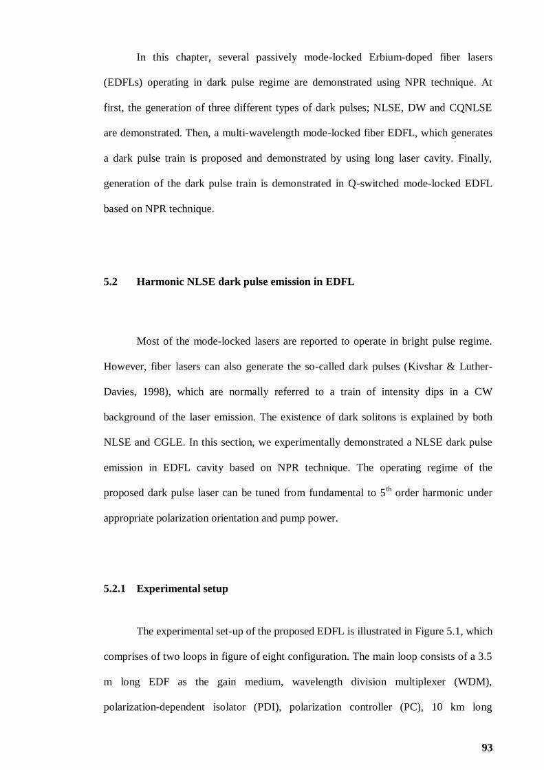
93
In this chapter, several passively mode-locked Erbium-doped fiber lasers
(EDFLs) operating in dark pulse regime are demonstrated using NPR technique. At
first, the generation of three different types of dark pulses; NLSE, DW and CQNLSE
are demonstrated. Then, a multi-wavelength mode-locked fiber EDFL, which generates
a dark pulse train is proposed and demonstrated by using long laser cavity. Finally,
generation of the dark pulse train is demonstrated in Q-switched mode-locked EDFL
based on NPR technique.
5.2 Harmonic NLSE dark pulse emission in EDFL
Most of the mode-locked lasers are reported to operate in bright pulse regime.
However, fiber lasers can also generate the so-called dark pulses (Kivshar & Luther-
Davies, 1998), which are normally referred to a train of intensity dips in a CW
background of the laser emission. The existence of dark solitons is explained by both
NLSE and CGLE. In this section, we experimentally demonstrated a NLSE dark pulse
emission in EDFL cavity based on NPR technique. The operating regime of the
proposed dark pulse laser can be tuned from fundamental to 5th order harmonic under
appropriate polarization orientation and pump power.
5.2.1 Experimental setup
The experimental set-up of the proposed EDFL is illustrated in Figure 5.1, which
comprises of two loops in figure of eight configuration. The main loop consists of a 3.5
m long EDF as the gain medium, wavelength division multiplexer (WDM),
polarization-dependent isolator (PDI), polarization controller (PC), 10 km long

94
dispersion shifted fiber (DSF) and two 3 dB couplers. The EDF used has a doping
concentration of 2000 ppm and group velocity dispersion (GVD) of about -21.64
ps/nm.km. This fiber was pumped by a 1480 nm laser diode via the WDM. The
secondary loop consists of a 100 m long highly nonlinear fiber (HNLF), which is
connected to the main loop by a 3 dB coupler. The HNLF has a dispersion of 0.15
(ps/nm)/km at 1550nm and effective area of 12.3 µm. A PDI was used in the cavity to
force a unidirectional operation of the ring, and an in-line PC was inserted in the cavity
to adjust the linear birefringence of the cavity. A 2 x 2 3 dB fiber coupler was used to
form a figure-of-eight structure with a piece of HNLF inserted in the new loop. The
output of the laser was collected from the cavity via a 3 dB coupler which retained 50%
of the light in the ring cavity to oscillate. The optical spectrum analyser (OSA,
Yokogawa, AQ 6370B) was used for spectral analysis of the proposed EDFL with a
spectral resolution of 0.02 nm whereas the oscilloscope was used to observe the output
pulse train of the dark pulse emission via a 1 GHz bandwidth photo-detector.

95
Figure 5.1: Schematic configuration of the proposed dark pulse EDFL
5.2.2 NLSE dark pulse performance
By carefully adjusting the PC orientation, dark pulse emission operating in
fundamental repetition rate of 20 kHz could be observed at pumping threshold power of
29 mW. The typical pulse train of the fundamental dark pulse is shown in Figure 5.2(a).
As shown in the figure, the dark pulse was represented as a narrow intensity dip in the
strong CW laser emission background. When the 10 km DSF was removed from cavity,
we were still able to observe dark pulse formation. However, the dark pulse train was
random and unstable. To obtain a stable dark pulse train of laser emission, it was
necessary to have a sufficient nonlinear gain in the cavity. Therefore, a 10 km DSF is
incorporated in the proposed laser cavity to provide a nonlinear gain, which is required
for the NPR process.

96
In addition, figure-of-eight setup also induced competition between two cavity
modes and cavity feedback, which played an important role in the stability of the dark
pulses in the laser. A harmonic dark pulse can also be formed in round trip time (RTT),
where the harmonic‟s order can be tuned by increasing the pump power as shown in
Figure 5.2(b)-(e). By carefully adjusting the PC, the operating frequency of the dark
pulse trains were shifted to 2nd
order, 3rd
order, 4th order and 5
th order harmonic as the
pump power was increased to 34 mW, 50 mW, 59 mW and 137 mW respectively. The
2nd
, 3rd
, 4th and 5
th harmonics correspond to repetition rates of 40 kHz, 60 kHz, 80 kHz
and 100 kHz, as shown in Figure 5.2(b), (c), (d) and (e) respectively.
(a)
(b)

97
(c)
(d)
(e)
Figure 5.2: Dark pulse emission of the proposed EDFL at different orders of harmonic:
(a) fundamental, (b) 2nd
, (c) 3rd
, (d) 4th
, and (e) 5th

98
Figure 5.3 shows threshold pump power to achieve different order of harmonics
and its corressponding output power at the threshold pump power. The fundamental
repetition rate is observed at 29 mW, whereas the 2nd
, 3rd
, 4th
and 5th order harmonics
are obtained at pump power of 34 mW, 50 mW, 59 mW and 137 mW respectively. As
the pump power is further increased to 150 mW and above, no higher harmonic order is
observed. This may be caused by the gain limitation which constrained the pulse from
further breaking beyond the 5th
order harmonic. In the presence of relatively high
pumping power, a single pulse circulating in the cavity can be split into several pulses.
In such regime, pulses are usually randomly located in the cavity. However, under
certain conditions they can self-arrange to create a stable and well organized pulse train
with repetition rates far beyond the fundamental mode spacing. It is observed that the
harmonic order increased as we increased the pump power. The output power also
increased from 0.86 mW to 2.86 mW as the harmonic order was changed from the
fundamental to the 5th
order harmonic. This was attributed to the pump power used
which was larger for the higher harmonic order.

99
Figure 5.3: Threshold pump power and output power at different order harmonic
Figure 5.4 shows the relationship of pulse width and pulse energy against
harmonic orders. Pulse width of the fundamental, 2nd
order, 3rd
order, 4th order and 5
th
order harmonic are obtained at 6.0 μs, 3.6 μs, 2.6 μs, 2.3 μs, and 2 μs respetively. The
pulse width reduces with the increment of harmonic order due to the higher pump power
used to achieve higher harmonic order. On the other hand, the pulse energy at threshold
pump power of different harmonic order fluctuates between 42.6 nJ to 17.8 nJ as shown
in Fig. 5.4. Figure 5.5 shows the output spectra of the EDFL at different harmonic
orders. It is observed that the operating wavelength of the laser is blue-shifted as the
harmonic order increases. This is attributed to the pump power, which is stronger at
higher order harmonic and thus the laser operates at a shorter wavelength due to the
Erbium gain saturation. It is observed that the operating wavelength of the laser shifts
from 1565 nm to 1560 nm as the operation changes from the fundamental repetition
rate, to the 5th
order harmonic.

100
Figure 5.4: Pulse width and pulse energy against different order harmonic
Figure 5.5: Output spectra of the dark pulse train at different order harmonics
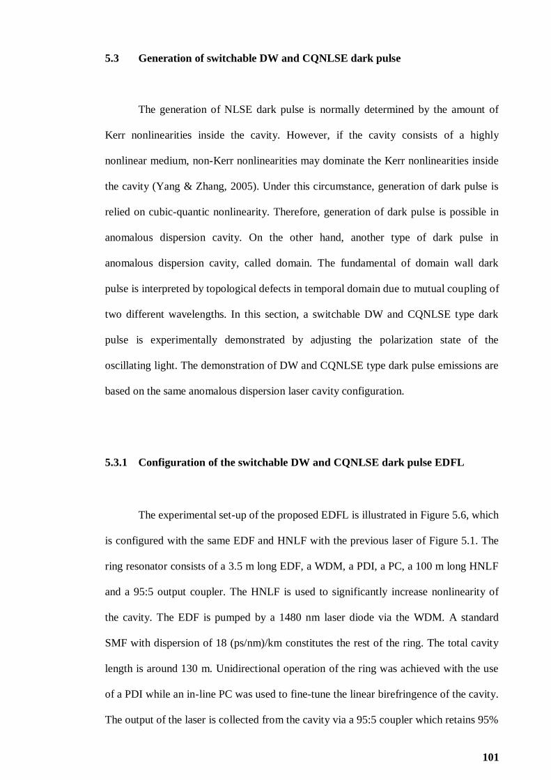
101
5.3 Generation of switchable DW and CQNLSE dark pulse
The generation of NLSE dark pulse is normally determined by the amount of
Kerr nonlinearities inside the cavity. However, if the cavity consists of a highly
nonlinear medium, non-Kerr nonlinearities may dominate the Kerr nonlinearities inside
the cavity (Yang & Zhang, 2005). Under this circumstance, generation of dark pulse is
relied on cubic-quantic nonlinearity. Therefore, generation of dark pulse is possible in
anomalous dispersion cavity. On the other hand, another type of dark pulse in
anomalous dispersion cavity, called domain. The fundamental of domain wall dark
pulse is interpreted by topological defects in temporal domain due to mutual coupling of
two different wavelengths. In this section, a switchable DW and CQNLSE type dark
pulse is experimentally demonstrated by adjusting the polarization state of the
oscillating light. The demonstration of DW and CQNLSE type dark pulse emissions are
based on the same anomalous dispersion laser cavity configuration.
5.3.1 Configuration of the switchable DW and CQNLSE dark pulse EDFL
The experimental set-up of the proposed EDFL is illustrated in Figure 5.6, which
is configured with the same EDF and HNLF with the previous laser of Figure 5.1. The
ring resonator consists of a 3.5 m long EDF, a WDM, a PDI, a PC, a 100 m long HNLF
and a 95:5 output coupler. The HNLF is used to significantly increase nonlinearity of
the cavity. The EDF is pumped by a 1480 nm laser diode via the WDM. A standard
SMF with dispersion of 18 (ps/nm)/km constitutes the rest of the ring. The total cavity
length is around 130 m. Unidirectional operation of the ring was achieved with the use
of a PDI while an in-line PC was used to fine-tune the linear birefringence of the cavity.
The output of the laser is collected from the cavity via a 95:5 coupler which retains 95%

102
of the light in the ring cavity to oscillate. The OSA with a spectral resolution of 0.02 nm
is used to analyze the spectrum of the proposed EDFL whereas the oscilloscope (OSC)
is employed in conjunction with a 1 GHz bandwidth photodetector to capture the output
pulse train of the dark pulse emission.
Figure 5.6: Experimental set-up of the proposed mode-locked EDFL, which capable for
generating a switchable DW and NLSE dark pulse train
5.3.2 DW dark pulse performance
In this work, NPR technique is used to generate a pulse train operating in dark
regime. The proposed laser operates in anomalous dispersion regime and the dark pulse
emission was considered as topological defects in temporal domain due to mutual
coupling of two different wavelengths. Under the optimum polarization setting, a DW
type dark pulse emission could be achieved as pump power is increased above the
pumping power threshold of 80 mW. The dark pulse train can be sustained until the
cavity‟s maximum pump power of 140 mW. Figure 5.7 shows the typical dark pulse

103
emission of the proposed laser, which operates at fundamental repetition rate of 1.52
MHz. As shown in the figure, the dark pulse is represented by a narrow intensity dip,
which exists in the strong continuous wave (CW) and the pulse width of the dark pulse
is measured to be about 203 ns. At the maximum pump power of 140 mW, the average
output power measured is about 3.4 mW, which can be translated to pulse energy of
2.24 nJ.
Figure 5.7: Typical DW dark pulse train at pump power of 140 mW
Figure 5.8 depicts the output spectrum of the DW dark pulse, which operates at
1580 nm region. It shows multiple peak wavelengths operation within a broad spectral
region. The spectral broadening is due to the self-phase modulation (SPM) effect in the
ring cavity. The laser oscillates simultaneously with multi peak wavelengths in the
cavity, leading to the emergence of topological defects in temporal domain. This
phenomena forms dark domain wall pulses, which have an intensity dip on a strong CW

104
background. The stability of DW dark pulse is then investigated by an RF spectrum
analyzer. As shown in Figure 5.9, the laser operates at fundamental frequency of 1.52
MHz with SNR of about 28 dB. This indicates the stability of the laser.
Figure 5.8: DW dark pulse spectrum of the proposed EDFL at pump power of 140 mW

105
Figure 5.9: DW dark pulse RF spectrum of the proposed EDFL at pump power of 140
mW
5.3.3 CQNLSE dark pulse performance
By carefully adjusting the PC, the operating regime of the mode-locked can be
switched from DW to CQNLSE as the pump power is increased above the threshold
pump power of 104 mW. The threshold pump power is reasonably higher than that of
the previous DW dark pulse emission. This is most probably due to the higher loss in
the cavity when the position of the PC is adjusted into the new position. By varying the
pump power from 104 mW to the maximum pump power of 140 mW, the CQNLSE
dark soliton pulse can be observed operating at fundamental pulse repetition rate of 1.52
MHz as shown in Figure 5.10. The pulse width of CQNLSE dark pulse is about 219 ns,
which is similar to DW dark pulse. The generation of CQNLSE is possible due to the
non-Kerr nonlinearities, which is stronger than the Kerr nonlinearities as the laser light
oscillates through the HNLF. This allows the formation of dark pulse with the assistance
of higher order of nonlinearity. The output power of CQNLSE dark pulse is measured to
be about 0.88 mW at the maximum pump power of 140 mW, which is comparatively
lower than that of DW dark pulse. This indicates a relatively low pulse energy of 0.58
nJ at pump power of 140 mW. Figure 5.11 decipts the output spectrum of CQNLSE
dark pulse, which clearly shows Kelly side bands. Unlike multiple peak wavelength
operation of DW dark pulse, CQNLSE dark pulse exhibits a single peak wavelength at
1564.5 nm, which is similar to NLSE type dark pulse. This is a significant indication
that differentiates between DW dark pulse and CQNLSE dark pulse. The cavity loss is
slightly higher in this laser and thus the operating wavelength shifts to a shorter
wavelength to acquire more gain to compensate the loss. The SNR of CQNLSE dark

106
pulse is obtained 35 dB, which is higher than the one of DW pulse, as shown in Figure
5.12. This shows that the generated CQNLSE pulse is more stable than the DW pulse.
Figure 5.10: CQNLSE dark pulse train of the proposed EDFL at pump power of 140
mW

107
Figure 5.11: Output optical spectrum of the CQNLSE dark pulse at pump power of 140
mW
Figure 5.12: RF spectrum of the CQNLSE dark soliton pulse at pump power of 140 Mw
5.4 Multi-wavelength dark pulse EDFL in figure-of-eight cavity
Both multi-wavelength and mode-locked EDFLs have wide applications in
optical communications, sensors and instrumentations. There are many different
methods that have been proposed to achieve multi-wavelength lasing at room
temperature such as cascaded stimulated Brillouin scattering, incorporating a
semiconductor optical amplifier or raman amplifier and four-wave mixing (FWM).
Recently, NPR which can induce intensity dependent loss in the laser cavity is also
widely used for multi-wavelength laser generation. On the other hand, mode-locked
EDFLs were demonstrated in the previous sections using NPR technique. The NPR

108
based lasers have shown promising results and attracted much attention for their
advantages such as compactness, low cost, flexibility and simplicity of design. As
discussed in chapter 4, NPR may not able to induce both multi-wavelength and pulse
generation in a single loop cavity. In this section, a mode-locked multi-wavelength
EDFL is demonstrated using figure-of-eight set up by incorporating 50 m long photonic
crystal fiber (PCF) and 20 km long standard SMF. The proposed EDFL setup is possible
to induce both multi-wavelength and dark pulse in an EDFL based on NPR mechanism.
Besides, figure-of-eight also induces higher cavity feedback, which allows the
generation of higher harmonic order. Under appropriate operation conditions, the
proposed fiber laser, which is configured with an all-normal dispersion and figure-of-
eight cavity could produce a train of single or multiple dark pulses.
5.4.1 Configuration of the proposed multi-wavelength dark pulse EDFL
The experimental set-up of the proposed EDFL is illustrated in Figure 5.13,
which the ring resonator consists of a 3.5 m long EDF as the gain medium, WDM, PDI,
polarization controller (PC), 50 m long PCF, 6.9 km long dispersion compensation fiber
(DCF) and 3 dB couplers. The EDF used has a doping concentration of 2000 ppm and
GVD parameter of about -21.64 (ps/nm)/km. This fiber was pumped by a 1480 nm laser
diode via the WDM. Other fibers in the cavity are a 6.9 km long DCF with GVD of
about -4 (ps/nm)/km and a standard SMF (18 ps/nm.km), which constituted the rest of
the ring. The cavity operates in large positive GVD where the net dispersion and
fundamental repetition rate are estimated as 35.19 ps2 and 29.0 kHz, respectively.
Unidirectional operation of the ring was achieved with the use of a PDI while an in-line
PC was used to fine-tune the linear birefringence of the cavity. A 2 x 2 3 dB fiber
coupler was used to form a figure-of-eight structure with a piece of PCF is inserted in

109
the new loop. The output of the laser is collected from the cavity via a 3 dB coupler
which retains 50% of the light in the ring cavity to oscillate. The OSA with a spectral
resolution of 0.02 nm is used to analyze the spectrum of the proposed EDFL whereas
the OSC is employed in conjunction with a 1 GHz bandwidth photodetector to capture
the output pulse train of the mode-locked operation.
Figure 5.13: Schematic configuration of the proposed multi-wavelength mode-locked
EDFL
5.4.2 Multi-wavelength dark pulse performance
We use the NPR technique for both mode locking and multi-wavelength
generation in the proposed ring EDFL. Under the optimum polarization setting, a multi-
wavelength laser output could be achieved in the laser as the pump power is increased
above the pumping power threshold of 24 mW. Figure 5.14 shows evolution of the

110
output spectrum of the multi-wavelength with 1480 nm pump power variation from 24
mW to 145 mW. It is observed that the number of lines and the peak power increase
with the pump power. At the maximum pump power of 145 mW, the laser produces at
least 9 lines with free spectral range (FSR) of 0.47 nm, which is determined by the
length and the effective group indices of the PCF. It is worth noting that there is no
multi-wavelength emission when the PCF is removed from the cavity. The multi-
wavelength generation is due to the intensity dependent loss induced by NPR. The role
of PCF is to increase the nonlinear effect as well as to constitute an inline periodic filter
with the PDI.
Figure 5.14: Multi-wavelength output spectrum evolution against 1480 nm pump power
As the pumping power exceeded 133 mW, self-started mode-locked pulse train
is obtained. Figures 5.15 and 5.16 show the optical spectrum and the oscilloscope trace

111
of the multi-wavelength laser respectively, at four diffferent orientation of PC. By
carefully adjusting the PC, dark pulse emission operating in fundamental repetition rate
of 29 kHz could be observed as shown in Figure 5.16 (a). As seen, in the time domain,
the dark pulse is represented as a narrow intensity dip in the strong CW laser emission
background. The full width at the half minimum of the dark pulse is about 2.7 µs. On
the OSA trace of Figure 5.15(a), the optical spectrum of the dark pulses shows a multi-
wavelength operation within a broad spectral region. The spectral broadening is due to
the SPM effect in the ring cavity. When the laser oscillates simultaneously at multiple
wavelengths in the cavity, the laser emission could switch between these wavelengths
due to their incoherent nonlinear coupling. This phenomena forms vector dark domain
wall pulses, which have an intensity dip on a strong CW background.

112
(a)
(b)
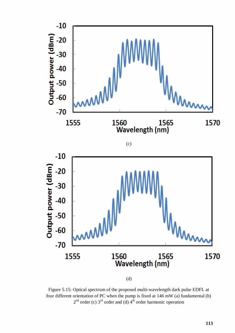
113
(c)
(d)
Figure 5.15: Optical spectrum of the proposed multi-wavelength dark pulse EDFL at
four different orientation of PC when the pump is fixed at 146 mW (a) fundamental (b)
2nd
order (c) 3rd
order and (d) 4th order harmonic operation

114
(a)
(b)
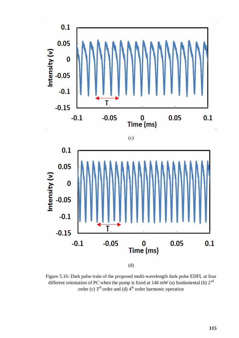
115
(c)
(d)
Figure 5.16: Dark pulse train of the proposed multi-wavelength dark pulse EDFL at four
different orientation of PC when the pump is fixed at 146 mW (a) fundamental (b) 2nd
order (c) 3rd
order and (d) 4th
order harmonic operation
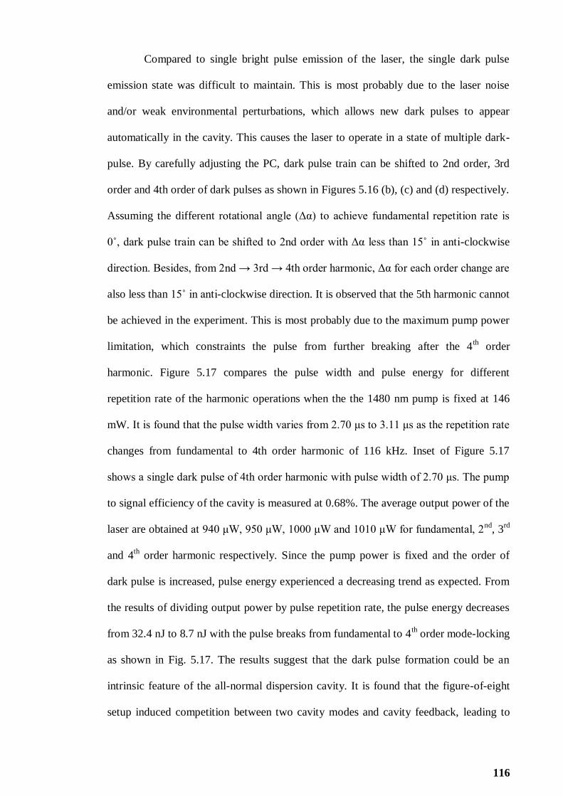
116
Compared to single bright pulse emission of the laser, the single dark pulse
emission state was difficult to maintain. This is most probably due to the laser noise
and/or weak environmental perturbations, which allows new dark pulses to appear
automatically in the cavity. This causes the laser to operate in a state of multiple dark-
pulse. By carefully adjusting the PC, dark pulse train can be shifted to 2nd order, 3rd
order and 4th order of dark pulses as shown in Figures 5.16 (b), (c) and (d) respectively.
Assuming the different rotational angle (Δα) to achieve fundamental repetition rate is
0˚, dark pulse train can be shifted to 2nd order with Δα less than 15˚ in anti-clockwise
direction. Besides, from 2nd → 3rd → 4th order harmonic, Δα for each order change are
also less than 15˚ in anti-clockwise direction. It is observed that the 5th harmonic cannot
be achieved in the experiment. This is most probably due to the maximum pump power
limitation, which constraints the pulse from further breaking after the 4th order
harmonic. Figure 5.17 compares the pulse width and pulse energy for different
repetition rate of the harmonic operations when the the 1480 nm pump is fixed at 146
mW. It is found that the pulse width varies from 2.70 μs to 3.11 μs as the repetition rate
changes from fundamental to 4th order harmonic of 116 kHz. Inset of Figure 5.17
shows a single dark pulse of 4th order harmonic with pulse width of 2.70 μs. The pump
to signal efficiency of the cavity is measured at 0.68%. The average output power of the
laser are obtained at 940 μW, 950 μW, 1000 μW and 1010 μW for fundamental, 2nd
, 3rd
and 4th
order harmonic respectively. Since the pump power is fixed and the order of
dark pulse is increased, pulse energy experienced a decreasing trend as expected. From
the results of dividing output power by pulse repetition rate, the pulse energy decreases
from 32.4 nJ to 8.7 nJ with the pulse breaks from fundamental to 4th order mode-locking
as shown in Fig. 5.17. The results suggest that the dark pulse formation could be an
intrinsic feature of the all-normal dispersion cavity. It is found that the figure-of-eight
setup induced competition between two cavity modes and cavity feedback, leading to
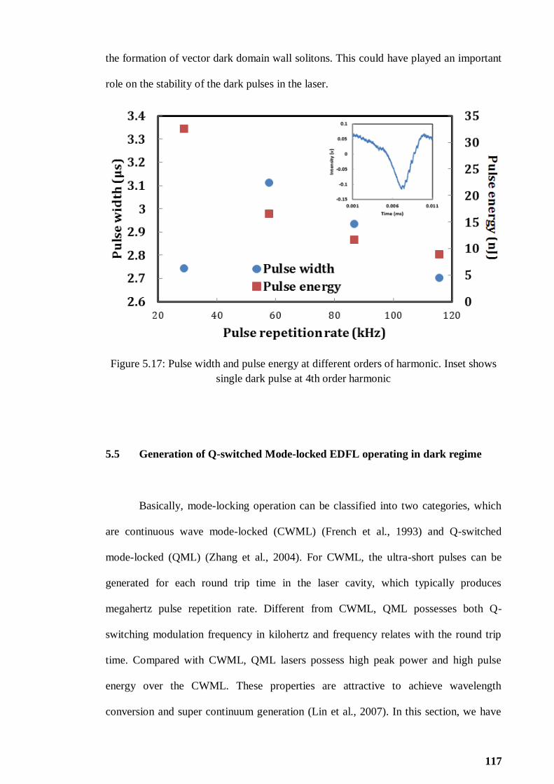
117
the formation of vector dark domain wall solitons. This could have played an important
role on the stability of the dark pulses in the laser.
Figure 5.17: Pulse width and pulse energy at different orders of harmonic. Inset shows
single dark pulse at 4th order harmonic
5.5 Generation of Q-switched Mode-locked EDFL operating in dark regime
Basically, mode-locking operation can be classified into two categories, which
are continuous wave mode-locked (CWML) (French et al., 1993) and Q-switched
mode-locked (QML) (Zhang et al., 2004). For CWML, the ultra-short pulses can be
generated for each round trip time in the laser cavity, which typically produces
megahertz pulse repetition rate. Different from CWML, QML possesses both Q-
switching modulation frequency in kilohertz and frequency relates with the round trip
time. Compared with CWML, QML lasers possess high peak power and high pulse
energy over the CWML. These properties are attractive to achieve wavelength
conversion and super continuum generation (Lin et al., 2007). In this section, we have
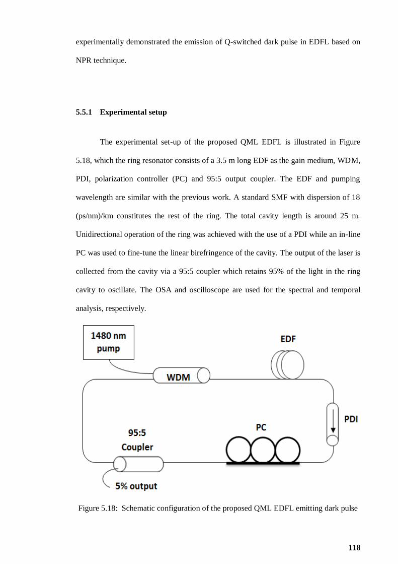
118
experimentally demonstrated the emission of Q-switched dark pulse in EDFL based on
NPR technique.
5.5.1 Experimental setup
The experimental set-up of the proposed QML EDFL is illustrated in Figure
5.18, which the ring resonator consists of a 3.5 m long EDF as the gain medium, WDM,
PDI, polarization controller (PC) and 95:5 output coupler. The EDF and pumping
wavelength are similar with the previous work. A standard SMF with dispersion of 18
(ps/nm)/km constitutes the rest of the ring. The total cavity length is around 25 m.
Unidirectional operation of the ring was achieved with the use of a PDI while an in-line
PC was used to fine-tune the linear birefringence of the cavity. The output of the laser is
collected from the cavity via a 95:5 coupler which retains 95% of the light in the ring
cavity to oscillate. The OSA and oscilloscope are used for the spectral and temporal
analysis, respectively.
Figure 5.18: Schematic configuration of the proposed QML EDFL emitting dark pulse

119
5.5.2 Q-switched dark pulse performance
At the optimum polarization orientation, Q-switched dark pulse is achieved as
pump power hits the pumping power threshold of 55 mW. The Q-switching pulse train
can be sustained up to the pump power of 145 mW. Figure 5.19 shows a typical pulse
train of the Q-switched dark pulse againsts pump power. In this experiment, we observe
that the multiple dark pulses are combined to form the Q-switched envelope, which
operates in dark regime as shown in Figure 5.20. Figure 5.21 shows the output spectrum
of the Q-switched laser at pump power of 145 mW. As shown in the figure, the laser
operates at wavelength around 1570 nm. Spectral broadening is also observed due to
self-phase modulation effect in the cavity.
Figure 5.19: Emission of Q-switched dark pulse train againsts pump power

120
Figure 5.20: Emission of single Q-switched dark pulse at pump power of 145 mW
Figure 5.21: Output spectrum at pump power of 145 mW

121
Even though the Q-switched envelope operates in dark regime, the pulse
characteristic is still in compliance with the conventional Q-switched operation. Figure
5.22 shows the repetition rate and pulse width of the Q-switched envelope of the
proposed EDFL against pump power. Pulse repetition rate is observed to proportionally
increase with the pump power. Pulse repetition rate increases from 0.96 kHz to 3.26
kHz by varying the pump power from 55 mW to 145 mW. The dependence of the pulse
width can be seen to decrease almost linearly with the pump power. Pulse width
decreases from 211 μs to 86 μs as pump power increases from 55 mW to 145 mW.
Figure 5.23 shows the relationship of average output power and pulse energy of the Q-
switched dark pulse EDFL with the pump power. As shown in the figure, average
output power increases almost linearly from 0.46 mW to 1.18 mW as the pump power
increases from 55 mW to 145 mW. Besides, the pulse energy fluctuates within 333 nJ to
479 nJ at the same pump power range.
Figure 5.22: Pulse repetition rate and pulse width of the proposed Q-switched dark pulse
EDFL

122
Figure 5.23: Output power and pulse energy of the proposed Q-switched dark pulse
EDFL
By zooming to the dark pulses inside the Q-switched envelope, we observe that
the pulse train consists of two different parts; the first dip and trailing dark pulses as
shown in the inset of Figure 5.24. The first dip represents the dark square pulse, whose
pulse width experiences a decreasing trend from 114 μs to 40.5 μs as pump power
increases from 55 mW to 145 mW. However, the negative peak intensity is
approximately constant at -96 mV throughout the tuning range of Q-switched dark pulse
operation as shown in Figure 5.24. For the trailing dark pulses, the repetition rate
increases from 27.62 kHz to 50 kHz as pump power increases from 55 mW to 145 mW.
The dark pulse generation inside the Q-switched pulse envelope is most probably due to
the Q-switching instability effect in the laser cavity. The dark pulse train in the cavity is
modulated by the Q-switching operation, which is created under a certain polarization
state based on NPR effect. The dark pulses are then bounded in a Q-switched envelope
to form a bunch of dark pulse as shown in Figure 5.20. The Q-switched modulation

123
process exhibits similar charateristics as the conventional Q-switching pulse operation,
which increases in pulse repetition rate and decreases in pulse width as pump power
increases. Therefore, the dark pulses under the Q-switched envelope are modulated and
complied to conventional Q-switching pulse operation. Commonly, the Q-switched
instability or QML cannot sustain under a wide pump power tuning range. It is worthty
to notice that in this experiment, the pump power tuning range of Q-switched dark pulse
operation is more than 90 mW. Q-switched modulation process has intensively increase
the negative peak amplitude and pulse energy for the dark pulse. These properties are
attractive to achieve wavelength conversion and super continuum generation.
Figure 5.24: Dark square pulse at different pump power, Inset shows single Q-switched
dark pulse which consists of first dip and trailing dark pulses

124
5.6 Summary
In this chapter, various types of dark pulse operations have been demonstrated
based on NPR techniques, which included NLSE dark pulse, CQNLSE dark pulse, DW
dark pulse, multi-wavelength dark pulse and Q-switched dark pulse in EDFL. It is found
that the NPR based dark pulses are highly relied on the cavity dispersion and
nonlinearity. For instance, NLSE dark pulse required normal dispersion cavity, DW
dark pulse required dual wavelength oscillation, and CQNLSE required high
nonlinearity to dominate the Kerr effect. Similar to mode-locking operation in chapter 4,
dark pulse generation required a polarization tuning process to achieve a stable pulsing
in dark regime. Compared to single bright pulse emission of the laser, the single dark
pulse emission state was difficult to maintain. This is most probably due to the laser
noise and/or weak environmental perturbations, which allows new dark pulses to appear
automatically in the cavity. In section 5.2 and section 5.4, harmonic dark pulses are
achieved in figure-of-eight cavity. This proved that figure-of-eight cavity can enhance
the cavity feedback and to achieve higher harmonic order as we have observed in
chapter 4. On the other hand, similar to multi-wavelength mode-locked that
demonstrated in chapter 4, multi-wavelength dark pulse is achieved in figure-of-cavity.
Dark pulse induced by NPR is formed in the main loop, whereas PCF in second loop
„sliced‟ the spectrum into multi-wavelength. Compare to pure dark pulse operation, Q-
switched dark pulse considered as an unstable state, in which both Q-switched and dark
pulse are co-existed in a same cavity. However, the amplitude of the dark pulse
increases tremendously with the Q-switched modulation process. This unstable state
carries an important advantage in certain application such as super continuum
generation.

125
CHAPTER 6
CONCLUSION AND FUTURE OUTLOOK
In this final chapter, we will summarize and conclude what has been demonstrated and
future outlook will be discussed.
6.1 Conclusion
Pulsed lasers have been of great interest as they have been widely used in
various fields such as micromachining, medicine and telecommunication. For instance,
ultra-short optical pulses have high potential applications optical transmission system
especially for achieving a high speed and long distance network. The generation of
pulsed laser can be categorized into two techniques; the active and passive techniques.
Passively mode-locked fiber lasers have become established tools for generating
nanosecond, picosecond and femtosecond pulses due to their compact design,
alignment-free waveguide format and low cost. These advantages over their solid-state
counterparts have driven further interest and more works on this field. This thesis aims
to propose and demonstrate both bright pulse and dark pulse train generations in
Erbium-doped fiber lasers (EDFLs) using passive techniques based on nonlinear
polarization rotation (NPR) technique. In this work, various techniques such as
saturable absorbers (SAs) and nonlinear polarization rotation (NPR) techniques have
been explored to generate the laser pulses.
Three passive techniques for generating Q-switching pulse have also been
evaluated and demonstrated; graphene film based SA, solid state thulium-doped fiber
(TDF) SA and NPR in Chapter 3. It is found that the NPR based Q-switching operation

126
occurs at a relatively lower pump power of around 12 mW compared to other Q-
switching techniques. Other techniques require higher pump power to initiate Q-
switching operation mainly due to the device loss. For instance, Q-switched EDFLs,
which were generated using a graphene and solid state TDF SA have a threshold pump
power in a range of 20 mW and 33 mW respectively. NPR technique proved its multi-
functional operation where we have successfully achieved both Q-switched and multi-
wavelength operations in our proposed EDFL. Furthermore, NPR also offers advantages
such as tunable saturable absorption strength and ease of implementation with only
conventional optical fiber components. Besides, NPR technique exhibits a high potential
to obtain different types of pulsed laser by only changing the polarization state.
Therefore, NPR technique is chosen to be the most suitable method for further
investigation in different type of pulsed laser.
In chapter 4, various types of mode-locking operations have been demonstrated
based on NPR techniques, which included mode-locked EDFL with switchable
operating states, mode-locked square pulse EDFL and multi-wavelength mode-locked
EDFL. It is found that the NPR based mode-locking operations are highly relied on the
polarization state. Therefore, different mode-locking operation can be generated in a
same cavity with the change of polarization state. On the other hand, pump power is
another key parameter to induce mode-locking operation based on NPR technique.
Under a sufficiently high pump power, mode-locked laser experiences pulse breaking
process to generate square pulse or higher order harmonic mode-locked. The advantages
of higher order harmonic mode-locked are to achieve higher pulse repetition rate and
narrower pulse width. On the other hand, the balance between the inhomogeneous loss
induced by NPR and the mode competition effect can lead stable multi-wavelength
oscillations. Multi-wavelength and mode-locking operation can be simultaneously
achieved in a single loop cavity set-up since mode-locking and multi-wavelength

127
operation required different NPR mechanism to induce the phenomena. However, multi-
wavelength and mode-locked are able to co-exist in figure-of-eight set-up; the main
loop induces the mode-locking operation, whereas another loop induces the multi-
wavelength operation to „slice‟ the spectrum of the cavity.
All the pulse train obtained in chapter 3 and chapter 4 are operated in bright
pulse regime. Besides the bright pulse regime, there is another type of operation regime,
called dark pulse regime. Dark pulse regime is represented as a narrow intensity dip
under a strong CW laser emission background. In chapter 5, several types of dark pulse
lasers are investigated via NPR method, which included NLSE dark pulse, CQNLSE
dark pulse, DW dark pulse, multi-wavelength dark pulse and Q-switched dark pulse in
EDFL. It is found that the NPR based dark pulses are highly relied on the cavity
dispersion and nonlinearity. For instance, NLSE dark pulse required normal dispersion
cavity, DW dark pulse required dual wavelength oscillation, and CQNLSE required
high nonlinearity to dominate the Kerr effect. Similar to mode-locked by NPR, dark
pulse generation required a polarization tuning process to achieve a stable pulsing in
dark regime. Compared to single bright pulse emission of the laser, the single dark pulse
emission state was difficult to maintain. This is most probably due to the laser noise
and/or weak environmental perturbations, which allows new dark pulses to appear
automatically in the cavity. Besides, harmonic dark pulses are achieved in figure-of-
eight cavity. This further identified that figure-of-eight cavity can enhance the cavity
feedback and to achieve higher harmonic order as we have observed in bright pulse
regime. Similar to multi-wavelength mode-locked that demonstrated in bright pulse
regime, multi-wavelength dark pulse is achieved in figure-of-cavity. Dark pulse induced
by NPR is formed in the main loop, whereas PCF in second loop „sliced‟ the spectrum
into multi-wavelength. Compare to pure dark pulse operation, Q-switched dark pulse is
considered to operate in an unstable state, where both Q-switching and dark pulse are

128
co-existed in the same cavity. However, the amplitude of the dark pulse tremendously
increases with the Q-switched modulation process. This unstable state carries an
important advantage in certain applications such as super continuum generation.
In summary, various types of bright and dark pulse profiles can be manipulated
based on the variable saturable absorption strengths of NPR technique. Therefore,
simple, compact and multi-function pulsed laser can be realized with NPR technique.
Characteristic of pulsed laser can be controlled to produce different pulse width and
pulse repetition rate that suit the needs for different applications. From the experiments
conducted and obtained results, it is proven that NPR is indeed a powerful tool that can
be exploited for pulsed laser
6.2 Recommendations for Future Works
Much work has been carried out on the generation of pulsed laser. However, it
can be further explored in the future. The performance of Q-switched pulse energy can
be improved, Future study on mode-locked and dark pulse based NPR may also focus
on higher pulse repetition rate and better signal to noise ratio (SNR).
Q-switched pulse energy of EDFL incorporated with SAs can further increase by
optimizing the gain medium length. Besides, Q-switched EDFL based on NPR can
incorporates a shorter nonlinear medium to decrease the cavity loss. Pulse width of
mode-locked EDFL can further be reduced by replacing the birefringence fiber (SMF,
DSF and DCF) with shorter nonlinear medium. Moreover, pulse width of NPR based
EDFL can also be made narrower, near transform limit by optimizing the net dispersion
in the cavity. Width the advancement of ultra-fast laser system, the cavity length can be
reduced to several meters to allow high pulse repetition rate in high capacity
telecommunication systems and optical switching devices. Additionally, high pulse

129
repetition rate can also be achieved with a higher pumping power to induce higher
harmonic order.
Future directions can also include comparison of pulse propagation
characteristics between bright and dark pulses to produce more reliable light source in
telecommunication field. With this, it is hoped that this work will contribute to the ultra-
fast optics.

130
REFERENCES
Adib, B., Heidari, A., & Tayyari, S. F. (2009). RETRACTED: An analytical approach
to soliton of the saturable non-linear Schrödinger equation determination and
consideration of stability of solitary solutions of cubic–quintic non-linear
Schrödinger equation (CQNLSE). Communications in Nonlinear Science and
Numerical Simulation, 14(5), 2034-2045.
Agrawal, G. P. (1987). Modulation instability induced by cross-phase modulation.
Physical review letters, 59(8), 880.
Agrawal, G. P., Baldeck, P. L., & Alfano, R. R. (1989). Modulation instability induced
by cross-phase modulation in optical fibers. Physical Review A, 39(7), 3406.
Agrawal, G. P., & Olsson, N. A. (1989). Self-phase modulation and spectral broadening
of optical pulses in semiconductor laser amplifiers. Quantum Electronics, IEEE
Journal of, 25(11), 2297-2306.
Alfano, R. R, & Ho, P. P. (1988). Self-, cross-, and induced-phase modulations of
ultrashort laser pulse propagation. IEEE Journal of Quantum Electronics, 24(2),
351-364.
Aubin, G., Jeanney, E., Montalant, T., Moulu, J., Pirio, F., Thomine, J. B. & Devaux, F.
(1995). 20 Gbit/s soliton transmission over transoceanic distances with a 105 km
amplifier span. Electronics Letters, 31(13), 1079-1080.
Baek, I. H., Lee, H. W., Bae, S., Hong, B. H., Ahn, Y. H., Yeom, D. I., & Rotermund,
F. (2012). Efficient mode-locking of sub-70-fs Ti: sapphire laser by graphene
saturable absorber. Applied Physics Express, 5(3), 032701.
Bonaccorso, F., Sun, Z., Hasan, T., & Ferrari, A. C. (2010). Graphene photonics and
optoelectronics. Nature photonics, 4(9), 611-622.
Bao, Q., Zhang, H., Wang, Y., Ni, Z., Yan, Y., Shen, Z. X., & Tang, D. Y. (2009).
Atomic layer graphene as a saturable absorber for ultrafast pulsed lasers.
Advanced Functional Materials, 19(19), 3077-3083.
Blow, K. J., & Doran, N. J. (1985). Multiple dark soliton solutions of the nonlinear
Schrödinger equation. Physics Letters A, 107(2), 55-58.
Brackett, C. A. (1990). Dense wavelength division multiplexing networks: Principles
and applications. Selected Areas in Communications, IEEE Journal on, 8(6),
948-964.
Buryak, A. V., Di Trapani, P., Skryabin, D. V., & Trillo, S. (2002). Optical solitons due
to quadratic nonlinearities: from basic physics to futuristic applications. Physics
Reports, 370(2), 63-235.

131
Chang, W., Ankiewicz, A., Soto-Crespo, J. M., & Akhmediev, N. (2008). Dissipative
soliton resonances. Physical Review A, 78(2), 023830.
Chen, H. R., Tsai, C. Y., Cheng, H. M., Lin, K. H., & Hsieh, W. F. (2014). Passive
mode locking of ytterbium-and erbium-doped all-fiber lasers using graphene
oxide saturable absorbers. Optics express, 22(11), 12880-12889.
Chen, L., Zhang, M., Zhou, C., Cai, Y., Ren, L. & Zhang, Z. (2009). Ultra-low
repetition rate linear-cavity erbium-doped fibre laser modelocked with
semiconductor saturable absorber mirror. Electronics letters, 45(14), 731-733.
Cordova-Plaza, A., Digonnet, M. J., & Shaw, H. J. (1987). Miniature CW and active
internally Q-switched Nd: MgO: LiNbO 3 lasers. Quantum Electronics, IEEE
Journal of, 23(2), 262-266.
Crosta, M., Fratalocchi, A., & Trillo, S. (2011). Bistability and instability of dark-
antidark solitons in the cubic-quintic nonlinear Schrödinger equation. Physical
Review A, 84(6), 063809.
Degnan, J. J. (1989). Theory of the optimally coupled Q-switched laser. Quantum
Electronics, IEEE Journal of, 25(2), 214-220.
Deng, L., Hagley, E. W., Wen, J., Trippenbach, M., Band, Y., Julienne, P. S., &
Phillips, W. D. (1999). Four-wave mixing with matter waves. Nature,
398(6724), 218-220.
Doran, N. J., & Wood, D. (1988). Nonlinear-optical loop mirror. Optics Letters, 13(1),
56-58.
Eichler, H. J., Liu, B., Kayser, M., & Khomenko, S. I. (1996). Er: YAG-laser at 2.94
μm Q-switched by a FTIR-shutter with silicon output coupler and polarizer.
Optical materials, 5(4), 259-265.
El-Sherif, A. F., & King, T. A. (2003). High-energy, high-brightness Q-switched Tm
3+-doped fiber laser using an electro-optic modulator. Optics communications,
218(4), 337-344.
Feng, M., Silverman, K. L., Mirin, R. P., & Cundiff, S. T. (2010). Dark pulse quantum
dot diode laser. Optics express, 18(13), 13385-13395.
Feng, X., Tam, H. Y., & Wai, P. K. A. (2006). Stable and uniform multiwavelength
erbium-doped fiber laser using nonlinear polarization rotation. Optics express,
14(18), 8205-8210.
Fermann, M. E., Haberl, F., Hofer, M., & Hochreiter, H. (1990). Nonlinear amplifying
loop mirror. Optics Letters, 15(13), 752-754.
Fok, M. P., & Shu, C. (2006). Spacing-adjustable multi-wavelength source from a
stimulated Brillouin scattering assisted erbium-doped fiber laser. Optics express,
14(7), 2618-2624.

132
Fukuda, H., Yamada, K., Shoji, T., Takahashi, M., Tsuchizawa, T., Watanabe, T., &
Itabashi, S. I. (2005). Four-wave mixing in silicon wire waveguides. Optics
Express, 13(12), 4629-4637.
Gao, M., Zuo, J. M., Twesten, R. D., Petrov, I., Nagahara, L. A., & Zhang, R. (2003).
Structure determination of individual single-wall carbon nanotubes by nanoarea
electron diffraction. Applied Physics Letters, 82(16), 2703-2705.
Giallorenzi, T. G., Bucaro, J. A., Dandridge, A., Sigel, G. H., Cole, J. H., Rashleigh, S.
C., & Priest, R. G. (1982). Optical fiber sensor technology. Microwave Theory
and Techniques, IEEE Transactions on, 30(4), 472-511.
Going, R., Popa, D., Torrisi, F., Sun, Z., Hasan, T., Wang, F. & Ferrari, A. C. (2012).
500fs wideband tunable fiber laser mode-locked by nanotubes. Physica E: Low-
Dimensional Systems and Nanostructures, 44(6), 1078-1081.
Haelterman, M., & Emplit, P. (1993). Optical dark soliton trains generated by passive
spectral filtering technique. Electronics Letters, 29(4), 356-357.
Han, Y. G., Van Anh Tran, T., & Lee, S. B. (2006). Wavelength-spacing tunable
multiwavelength erbium-doped fiber laser based on four-wave mixing of
dispersion-shifted fiber. Optics letters, 31(6), 697-699.
Harun, S. W., Parvizi, R., Shahi, S., & Ahmad, H. (2009). Multi-wavelength erbium-
doped fiber laser assisted by four-wave mixing effect. Laser Physics Letters,
6(11), 813-815.
Haus, H. A., Ippen, E. P. & Tamura, K. (1994). Additive-pulse modelocking in fiber
lasers. Quantum Electronics, Journal of IEEE, 30(1), 200-208.
Haus, H. A., Tamura, K., Nelson, L. E., & Ippen, E. P. (1995). Stretched-pulse additive
pulse mode-locking in fiber ring lasers: theory and experiment. Quantum
Electronics, IEEE Journal of, 31(3), 591-598.
Haus, H. A. (2000). Mode-locking of lasers. Selected Topics in Quantum Electronics,
IEEE Journal of, 6(6), 1173-1185.
Hossain, M. A., Namihira, Y. & Razzak, S. A. (2012). Supercontinuum generation at
1.55μm using highly nonlinear photonic crystal fiber for telecommunication and
medical applications. Optical Review, 19(5), 315-319.
Huang, P. L., Lin, S. C., Yeh, C. Y., Kuo, H. H., Huang, S. H., Lin, G. R., & Cheng, W.
H. (2012). Stable mode-locked fiber laser based on CVD fabricated graphene
saturable absorber. Optics express, 20(3), 2460-2465.
Hudson, D. D., Holman, K. W., Jones, R. J., Cundiff, S. T., Ye, J., & Jones, D. J.
(2005). Mode-locked fiber laser frequency-controlled with an intracavity
electro-optic modulator. Optics letters, 30(21), 2948-2950.

133
Ilday, F.Ö., Wise, F.W. & Sosnowski, T. (2002). High-energy femtosecond stretched-
pulse fiber laser with a nonlinear optical loop mirror. Optics letters, 27(17),
1531-1533.
Im, J. H., Choi, S. Y., Rotermund, F., & Yeom, D.I. (2010). All-fiber Er-doped
dissipative soliton laser based on evanescent field interaction with carbon
nanotube saturable absorber. Optics express, 18(21), 22141-22146.
Ippen, E. P., & Stolen, R. H. (1972). Stimulated Brillouin scattering in optical fibers.
Applied Physics Letters, 21(11), 539-541.
Ippen, E. P. (1994). Principles of passive mode locking. Applied Physics B, 58(3), 159-
170.
Isomäki, A., & Okhotnikov, O. G. (2006). Femtosecond soliton mode-locked laser
based on ytterbium-doped photonic bandgap fiber. Optics express, 14(20), 9238-
9243.
Jabczynski, J., Zendzian, W., & Kwiatkowski, J. (2006). Q-switched mode locking with
acousto-optic modulator in a diode-pumped Nd: YVO4 laser. Optics express,
14(6), 2184-2190.
Jeon, M. Y., Lee, H. K., Kim, K. H., Lee, E. H., Oh, W. Y., Kim, B.Y., & Koh, Y. W.
(1998). Harmonically mode-locked fiber laser with an acousto-optic modulator
in a Sagnac loop and Faraday rotating mirror cavity. Optics communications,
149(4), 312-316.
Kaiser, R., & Huttl, B. (2007). Monolithic 40-GHz mode-locked MQW DBR lasers for
high-speed optical communication systems. Selected Topics in Quantum
Electronics, IEEE Journal of, 13(1), 125-135.
Keller, U. (2003). Recent developments in compact ultrafast lasers. Nature, 424(6950),
831-838.
Kezirian, G. M. & Stonecipher, K. G. (2004). Comparison of the IntraLase femtosecond
laser and mechanical keratomes for laser in situ keratomileusis. Journal of
Cataract & Refractive Surgery, 30(4), 804-811.
Kim, A. D., Kutz, J. N., & Muraki, D. J. (2000). Pulse-train uniformity in optical fiber
lasers passively mode-locked by nonlinear polarization rotation. Quantum
Electronics, IEEE Journal of, 36(4), 465-471.
Kivshar, Y. S., & Luther-Davies, B. (1998). Dark optical solitons: physics and
applications. Physics Reports, 298(2), 81-197.
Kong, J., Cassell, A. M., & Dai, H. (1998). Chemical vapor deposition of methane for
single-walled carbon nanotubes. Chemical Physics Letters, 292(4), 567-574.
Laubereau, A., & Kaiser, W. (1974). Generation and applications of passively mode-
locked picosecond light pulses. Opto-electronics, 6(1), 1-24.

134
Lega, J., & Fauve, S. (1997). Traveling hole solutions to the complex Ginzburg-Landau
equation as perturbations of nonlinear Schrödinger dark solitons. Physica D:
Nonlinear Phenomena, 102(3), 234-252.
Lehmann, K. K., & Romanini, D. (1996). The superposition principle and cavity ring-
down spectroscopy. The Journal of chemical physics, 105(23), 10263-10277.
Lin, J. H., Lin, K. H., Hsu, C. C., Yang, W. H., & Hsieh, W. F. (2007). Supercontinuum
generation in a microstructured optical fiber by picosecond self Q-switched
mode-locked Nd: GdVO4 laser. Laser Physics Letters, 4(6), 413.
Liu, X. M., Wang, T., Shu, C., Wang, L.R., Lin, A., Lu, K.Q. & Zhao, W. (2008).
Passively harmonic mode-locked erbium-doped fiber soliton laser with a
nonlinear polarization rotation. Laser physics, 18(11), 1357-1361.
Liu, X. (2009). Dissipative soliton evolution in ultra-large normal-cavity-dispersion
fiber lasers. Optics express, 17(12), 9549-9557.
Luo, A.P., Luo, Z. C., Xu, W., Dvoyrin, V. V., Mashinsky, V. M. & Dianov, E. M.
(2011). Tunable and switchable dual-wavelength passively mode-locked Bi-
doped all-fiber ring laser based on nonlinear polarization rotation. Laser Physics
Letters, 8(8), 601-605.
Luo, Z., Zhou, M., Weng, J., Huang, G., Xu, H., Ye, C. & Cai, Z. (2010). Graphene-
based passively Q-switched dual-wavelength erbium-doped fiber laser. Optics
letters, 35(21), 3709-3711.
Martinez, A., & Sun, Z. (2013). Nanotube and graphene saturable absorbers for fibre
lasers. Nature Photonics, 7(11), 842-845.
Matsas, V. J., Newson, T. P., Richardson, D. J. & Payne, D. N. (1992). Selfstarting
passively mode-locked fibre ring soliton laser exploiting nonlinear polarisation
rotation. Electron. Lett, 28(15), 1391-1393.
Mendez, A. J., Gagliardi, R. M., Feng, H. X., Heritage, J. P., & Morookian, J. M.
(2000). Strategies for realizing optical CDMA for dense, high-speed, long span,
optical network applications. Journal of lightwave technology, 18(12), 1685.
Montés-Micó, R., Rodríguez-Galietero, A. & Alió, J. L. (2007). Femtosecond laser
versus mechanical keratome LASIK for myopia. Ophthalmology, 114(1), 62-68.
Mori, K., Takara, H., Kawanishi,S., Saruwatari, M. & Morioka, T. (1997). Flatly
broadened supercontinuum spectrum generated in a dispersion decreasing fibre
with convex dispersion profile. Electronics Letters, 33(21), 1806-1808.
Mulvad, H. C. H., Galili, M., Oxenløwe, L. K, Hu, H., Clausen, A. T., Jensen, J. B.,
Peucheret, C. & Jeppesen, P. (2010). Demonstration of 5.1 Tbit/s data capacity
on a single-wavelength channel. Optics Express, 18(2), 1438-1443.

135
Nakazawa, M. (2000). Solitons for breaking barriers to terabit/second WDM and
OTDM transmission in the next millennium. Selected Topics in Quantum
Electronics, Journal of IEEE, 6(6), 1332-1343.
Nakazawa, M., Yamada, E., Kubota, H. & Suzuki, K. (1991). 10 Gbit/s soliton data
transmission over one million kilometres. Electronics Letters, 27(14), 1270-
1272.
Nelson, L. E., Jones, D. J., Tamura, K., Haus, H. A., & Ippen, E. P. (1997). Ultrashort-
pulse fiber ring lasers. Applied Physics B: Lasers and Optics, 65(2), 277-294.
Nikumb, S., Chen, Q., Li, C., Reshef, H., Zheng, H. Y., Qiu, H. & Low, D. (2005).
Precision glass machining, drilling and profile cutting by short pulse lasers. Thin
Solid Films, 477(1), 216-221.
Noor, Y. M., Tam, C. C., Lim, L.E. N. & Jana, S. (1994). A review of the Nd: YAG
laser marking of plastic and ceramic IC packages. Journal of materials
procecssing technology, 42(1), 95-133
Pan, S. D., Cui, L., Liu, J. Q., Teng, B., Liu, J. H., & Ge, X. H. (2014). Passively Q-
switched mode-locking Nd: GdVO 4 laser with a chemically reduced graphene
oxide saturable absorber. Optical Materials, 38, 42-45.
Pitois, S., Fatome, J., & Millot, G. (2002). Generation of a 160-GHz transform-limited
pedestal-free pulse train through multiwave mixing compression of a dual-
frequency beat signal. Optics letters, 27(19), 1729-1731.
Plamann, K., Aptel, F., Arnold, C. L., Courjaud, A., Crotti, C., Deloison, F. & Legeais,
J.- M. (2010). Ultrashort pulse laser surgery of the cornea and the sclera. Journal
of Optics, 12(8), 084002.
Radhakrishnan, R., & Lakshmanan, M. (1995). Bright and dark soliton solutions to
coupled nonlinear Schrodinger equations. Journal of Physics A: Mathematical
and General, 28(9), 2683.
Rairoux, P., Schillinger, H., Niedermeier, S., Rodriguez, M., Ronneberger, F.,
Sauerbrey, R., ... & Ziener, C. (2000). Remote sensing of the atmosphere using
ultrashort laser pulses. Applied Physics B, 71(4), 573-580.
Renninger, W. H., Chong, A., & Wise, F. W. (2010). Self-similar pulse evolution in an
all normal-dispersion laser. Physical Review A, 82(2), 021805.
Salehi, J. A., Weiner, A. M., & Heritage, J. P. (1990). Coherent ultrashort light pulse
code-division multiple access communication systems. Lightwave Technology,
Journal of, 8(3), 478-491.
Salhi, M., Leblond, H., & Sanchez, F. (2003). Theoretical study of the erbium-doped
fiber laser passively mode-locked by nonlinear polarization rotation. Physical
Review A, 67(1), 013802.

136
Serkin, V. N., & Hasegawa, A. (2000). Novel soliton solutions of the nonlinear
Schrödinger equation model. Physical Review Letters, 85(21), 4502.
Serbin, J., Bauer, T., Fallnich, C., Kasenbacher, A. & Arnold, W. H. (2002).
Femtosecond lasers as novel tool in dental surgery. applied surface science, 197,
737-740.
Set, S. Y., Yaguchi, H., Tanaka, Y., & Jablonski, M. (2004). Laser mode locking using
a saturable absorber incorporating carbon nanotubes. Journal of Lightwave
Technology, 22(1), 51.
Shahabuddin, N. S., Mohamad, H., Mahdi, M. A., Yusoff, Z., Ahmad, H. & Harun, S.
W. (2012). Broad spectral sliced multiwavelength source with a mode locked
fiber laser. Laser Physics, 22(1), 212-215.
Song, C., Xu, W., Luo, Z., Luo, A. & Chen, W. (2009). Switchable and tunable dual-
wavelength ultrashort pulse generation in a passively mode-locked erbium-
doped fiber ring laser. Optics Communications, 282(22), 4408-4412.
Sotor, J., Sobon, G., Krzempek, K. & Abramski, K. M. (2012). Fundamental and
harmonic mode-locking in erbium-doped fiber laser based on graphene saturable
absorber. Optics Communications, 285(13), 3174-3178.
Stegeman, G. I., Hagan, D. J., & Torner, L. (1996). χ (2) cascading phenomena and their
applications to all-optical signal processing, mode-locking, pulse compression
and solitons. Optical and Quantum electronics, 28(12), 1691-1740.
Stolen, R. H., & Lin, C. (1978). Self-phase-modulation in silica optical fibers. Physical
Review A, 17(4), 1448.
Sutter, D. H., Steinmeyer, G., Gallmann, L., Matuschek, N., Morier-Genoud, F., Keller,
U., & Tschudi, T. (1999). Semiconductor saturable-absorber mirror assisted
Kerr-lens mode-locked Ti: sapphire laser producing pulses in the two-cycle
regime. Optics Letters, 24(9), 631-633.
Sylvestre, T., Coen, S., Emplit, P., & Haelterman, M. (2002). Self-induced modulational
instability laser revisited: normal dispersion and dark-pulse train generation.
Optics letters, 27(7), 482-484.
Tang, D. Y., Li, L., Song, Y. F., Zhao, L. M., Zhang, H., & Shen, D. Y. (2013).
Evidence of dark solitons in all-normal-dispersion-fiber lasers. Physical Review
A, 88(1), 013849.
Tang, W. W., Shu, C., & Lee, K. L. (2001). Rational harmonic mode locking of an
optically triggered fiber laser incorporating a nonlinear optical loop modulator.
Photonics Technology Letters, IEEE, 13(1), 16-18.
Triki, H., Crutcher, S., Yildirim, A., Hayat, T., Aldossary, O. M., & Biswas, A. N. J. A.
N. (2012). Bright and dark solitons of the modified complex Ginzburg Landau

137
equation with parabolic and dual-power law nonlinearity. Romanian Reports in
Physics, 64(2), 357-366.
Wu, X., Tang, D. Y., Zhang, H., & Zhao, L. M. (2009). Dissipative soliton resonance in
an all-normal-dispersion erbium-doped fiber laser. Optics express, 17(7), 5580-
5584.
Xu, K., Wu, J., Hong, X. B. & Lin, J. T. (2008). Two different operation regimes of
fiber laser based on nonlinear polarization rotation: passive mode-locking and
multiwavelength emission. Photonics Technology Letters, IEEE, 20(12), 979-
981.
Yang, Q., & Zhang, J. F. (2005). Optical Quasi-Soliton Solutions for the Cubic-Quintic
Nonlinear SCHRÖDINGER Equation with Variable Coefficients. International
Journal of Modern Physics B, 19(31), 4629-4636.
Yoo, W. S., Kang, K., Ueda, T., & Ishigaki, T. (2009). Design of multi-wavelength
micro Raman spectroscopy system and its semiconductor stress depth profiling
applications. Applied physics express, 2(11), 116502.
Yu, Z., Wang, Y., Zhang, X., Dong, X., Tian, J., & Song, Y. (2014). A 66 fs highly
stable single wall carbon nanotube mode locked fiber laser. Laser Physics, 24(1),
015105.
Zhang, H., Tang, D. Y., Zhao, L. M., & Knize, R. J. (2010). Vector dark domain wall
solitons in a fiber ring laser. Optics express, 18(5), 4428-4433.
Zhang, H., Tang, D., Zhao, L., & Wu, X. (2011). Dual-wavelength domain wall solitons
in a fiber ring laser. Optics express, 19(4), 3525-3530.
Zhang, J., & Dai, C. (2005). Bright and dark optical solitons in the nonlinear
Schrodinger equation with fourth-order dispersion and cubic-quintic
nonlinearity. Chinese Optics Letters, 3(5), 295-298.
Zhang, S., Wu, E., Pan, H., & Zeng, H. (2004). Q-switched mode-locking with Cr4+:
YAG in a diode pumped Nd: GdVO4 laser. Applied Physics B, 78(3-4), 335-
338.
Zhang, X., Zhao, S., Wang, Q., Ozygus, B., & Weber, H. (1999). Modeling of diode-
pumped actively Q-switched lasers. Quantum Electronics, IEEE Journal of,
35(12), 1912-1918.
Zhang, X., Zhao, S., Wang, Q., Ozygus, B., & Weber, H. (2000). Modeling of passively
Q-switched lasers. JOSA B, 17(7), 1166-1175.
Zhang, X., Zhao, S., Wang, Q., Zhang, Q., Sun, L., & Zhang, S. (1997). Optimization of
Cr 4+-doped saturable-absorber Q-switched lasers. Quantum Electronics, IEEE
Journal of, 33(12), 2286-2294.

138
Zhao, W., & Bourkoff, E. (1990). Generation of dark solitons under a cw background
using waveguide electro-optic modulators. Optics letters, 15(8), 405-407.
Zhu, J., Zhang, D., Bian, Z., Li, G., Huo, Y., Lu, Y., & Li, H. (2009). Aerosol-spraying
synthesis of SiO 2/TiO 2 nanocomposites and conversion to porous TiO 2 and
single-crystalline TiOF 2. Chemical Communications, (36), 5394-5396.

139
APPENDIX
A selection of published works are attached in this appendix